

Page 1
Warranty
• DuraTrax™will warranty this kit for 90 days after the purchase date from defects in materials or
workmanship. DuraTrax
will either repair or replace, at no charge, the incorrectly made part.
• Make sure you save the receipt or invoice you were given when you bought your model! It is your proof of purchase
and we must see it before we can honor the warranty.
• To return your Thunder Quake for repairs covered under warranty you should send your tr uck to:
Hobby Services
1610 Interstate Drive
Champaign, Illinois 61822
Attn: Service Department
Phone: (217) 398-0007 9:00 am - 5:00 pm Central Time M-F
E-mail:
hobbyservices@hobbico.com
Before Building:
We want the building and operating of this vehicle to be a success, so BEFORE removing any parts from the parts bags
please read this manual thoroughly and watch the included video to familiarize yourself with the model. If for any reason
you think this model is not for you, return it to your dealer immediately.PLEASE NOTE:Your hobby dealer cannot accept
a return on any model after assembly has begun.
© Copyright 2001 DTXZ1093 For Kit DTXD74**
ASSEMBLY AND OPERATION MANUAL
TM
®
Patent Pending
TM
Page 2

Introduction.......................................................................2
Safety Precautions...........................................................2
Helpful Hints.....................................................................2
Stress-Tech™Parts Guarantee ........................................2
Repair Service ..................................................................3
Specification & Description Changes............................3
Screw Information............................................................3
Required Items for Completion.......................................3
T ools Y ou Will Need..........................................................3
Thunder Quake Final Assembly .....................................4
Antenna Installation.........................................................4
Air Filter Installation ........................................................4
Radio Setup ......................................................................5
Body ..................................................................................6
Forward / Reverse Operation..........................................6
Carburetor Settings..........................................................6
Breaking in the Engine....................................................7
Running the Engine .........................................................7
Engine Maintenance.........................................................8
Performance Tuning.........................................................9
Maintenance Tips............................................................10
Engine T rouble Shooting ...............................................11
Thank you for purchasing the DuraTrax Thunder Quake.
This manual contains the instructions you need to build,
operate and maintain your new nitro R/C monster truck.
Read over this manual thoroughly before building or
operating the Thunder Quake.
When the safety precautions are followed, the Thunder
Quake will provide years of enjoyment. Use care and good
sense at all times when operating this radio controlled
monster truck. Failure to use this vehicle in a safe, sensible
manner can result in injury or damage to proper ty. You and
you alone must insure that the instructions are carefully
followed and all safety precautions are obeyed.
• Do not operate the Thunder Quake near people.
Spectators should be behind the driver or at a safe
distance away from the vehicle.
• The engine and exhaust produces quite a bit of noise. If
you are disturbed by the amount of noise this truck
produces, wear ear protection such as earplugs. Do not
run this vehicle when or where it can disturb others.
• The engine and exhaust can become very hot. Avoid
touching any of these parts during use and until they
have cooled down.
• Model engine fuel is poisonous.Make sure you read and
follow all of the precautions on the fuel container. Keep
fuel out of the reach of children.
• Model engine fuel is flammable and when ignited has a
flame that is difficult to see. Avoid sparks, flames,
smoking, or any other ignition source when fuel is near.
• The engine emits carbon dioxide just like real cars. Do
not operate this model indoors.
• Before turning on the transmitter, make sure that no one
else is on your frequency.
• A void w orking ov er a deep pile carpet.If y ou drop a small
part or screw, it will be difficult to find.
• Place a mat or towel o ver your w ork surface.This will prevent
parts from rolling off and will protect the work surface.
• Avoid running the tr uck in cold weather. The plastic and
metal parts can become brittle at low temperatures. In
addition, grease and oil become thick, causing premature
wear and poor performance.
• Test fit all parts before attaching them permanently.
We have engineered the Thunder Quake to take the rough
and tumble abuse that makes R/C monster trucks fun.We
are so confident of the quality and durability of the StressTech™plastic parts that we will replace any Stress-Tech
plastic part you break during the first year you own the truck.
Just send in the part to us and we will send you a Free
replacement. Please see the Thunder Quake parts list for
the items covered under the Stress-Tech guarantee.
To receive your free replacement part please send the
following to the Hobby Ser vices address listed on the cover
of this manual:
• The broken part must be included.
• The part number and description of the broken part.
• Dated copy of your invoice or purchase receipt.
• Your name, phone number and shipping address.
STRESS-TECH™PARTS GUARANTEE
HELPFUL HINTS
SAFETY PRECAUTIONS
INTRODUCTION
TABLE OF CONTENTS
2
Page 3
Repair service is available anytime.
• After the 90 day w arranty, you can still hav e your Thunder
Quake repaired for a small charge by the experts at
DuraTrax’s authorized repair facility, Hobby Ser vices, at
the address listed on the front page of this manual.
To speed up the repair process, please follow the
instructions listed below.
1. Under most circumstances return the ENTIRE system: truck
and radio.The exception would be sending in a Stress-Tech
part. See the instructions under Stress-Tech Guarantee.
2. Make sure the transmitter is turned off, all batteries are
removed and fuel is drained from the tank.
3. Send written instructions which include: a list of all items
returned, a THOROUGH explanation of the problem, the
service needed and your phone number during the day. If
you expect the repair to be covered under warranty, be
sure to include a proof of date of purchase (your store
receipt or purchase invoice).
4. Also be sure to include your full return address.
All pictures, descriptions and specifications found in this
instruction manual are subject to change without notice.
DuraTrax maintains no responsibility for inadvertent errors
in this manual.
Do not use too much force when tightening self-tapping
screws into plastic. Overtightening will cause the threads in
the plastic to strip. We recommend that you stop turning a
self-tapping screw when you feel some resistance as the
head of the screw comes in contact with the plastic. Avoid
using powered screwdrivers when assembling this kit. They
tend to overtighten the screws. Do not use thread locking
compound on any self-tapping screws. The thread locking
compound may damage the plastic. IMPORTANT: Use
thread lock on any fastener that is threaded into metal or
fastened with a nut.Vibration from the engine will cause the
screws to loosen if thread locking compound is not used.
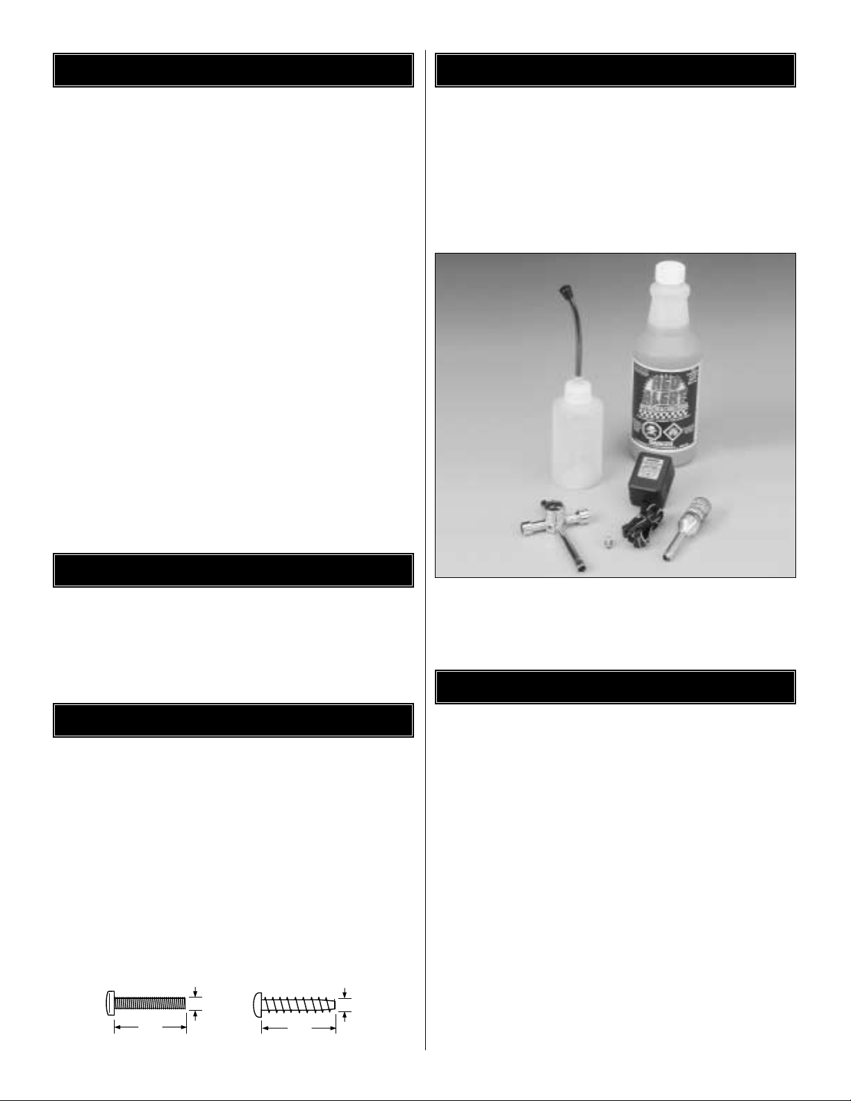
To operate the Thunder Quake these items are required:
• Fuel (DuraTrax Red Alert fuel - DTXP0520)
• Air Filter Oil (DTXC2465)
• It is also helpful to have a couple of extra glow plugs
on hand (Duratrax Silver Sport - DTXG3001)
(All of these items are available in a Nitro Starter Pack
from DuraTrax - DTXP0200).
• Phillips head screwdriver (DTXR0122)
• Needle-nose pliers (DTXR0300)
• Wire cutters or diagonal cutters (DTXR0302)
TOOLS Y OU WILL NEED
REQUIRED ITEMS FOR COMPLETION
SCREW INFORMATION
SPECIFICATION & DESCRIPTION CHANGES
REPAIR SERVICE
3
M3x14
M3x14 Screw
3mm
14mm
Self-Tapping
Screw
3mm
14mm
Page 4
❏ 1. Remove the Thunder Quake, transmitter and parts
from the box.
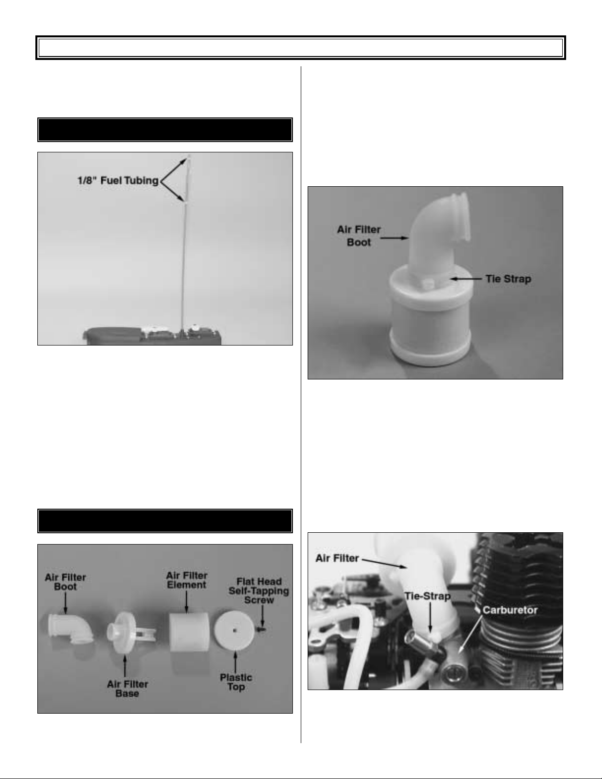
❏2.Remov e the twist-tie from the receiv er antenna wire.The
receiver antenna wire is a bundled thin wire that is attached
to the receiver. Run the length of the antenna wire through
your fingers to help straighten the wire out, this will make it
easier to get the wire through the tube. Remove the antenna
tube from the decal bag. Slide the antenna wire through the
antenna tube. Do not coil or cut the antenna. Cut two
pieces of fuel tubing 1/8" wide and slide them over the outside
of the antenna tube and wire.This is to help hold the antenna
tube on and avoid getting the antenna wire cut in a roll over.
Note the placement of the tubing on the antenna tube.
❏ 3. Remove the air filter parts from the parts pack.
Remove the flat head self-tapping screw from the top of the
air filter and remove the plastic top. Remove the air filter
element and thoroughly soak it in air filter oil, light machine
oil, or (in a pinch) shock oil. Reinstall the air filter element,
plastic top and flat head self-tapping screw.
❏4.Press the “L”shaped boot onto the bottom housing of the
air filter. Using one of the included tie-straps, tightly secure
the boot onto the bottom housing. Cut off the excess portion
of the tie-strap.
❏ 5. Place the air filter onto the carburetor. Using the
remaining included tie-strap, tightly secure the air filter to
the carburetor. Cut the excess portion of the tie-strap off to
avoid interference.
AIR FILTER INSTALLATION
ANTENNA INSTALLATION
4
THUNDER QUAKE FINAL ASSEMBLY
Page 5

❏6. Remove the receiver battery holder from the radio box.
Install (4) “AA” batteries (included) into the battery holder in
the configuration molded into the battery holder.
❏7. Cut a piece of foam the size of the radio box and place
it in the bottom for all of the equipment to set on. Re-install
the receiver battery into the radio box. Note the placement
of the receiver battery in the box. Make sure that the
receiver switch is in the “off” position. Plug the connector on
the receiver battery into the socket on the receiver switch.
Wrap the receiver with the included foam rubber (if desired,
secure with a rubber band, not included) to help reduce
possible radio interference from vibration.
❏8.Remove the tr ansmitter antenna from the holder and screw
it into the hole on top of the transmitter. Give the transmitter
antenna a light tug to make sure it is threaded on properly.
❏ 9. Slide open the battery door on the bottom of the
transmitter.Place 8 “AA” batteries (included) into the holder
in the configuration molded into the plastic on the battery
holder.Re-install the battery door.
❏ 10. Turn on the transmitter using the switch on the side
(see photo with step 8). The red light on the side of the
transmitter should light up. If there is no light on, turn the
transmitter off and check to ensure that the batteries are
making contact with the contacts on the inside of the battery
compartment. Make sure the batteries are installed correctly.
Turn the transmitter on and check for the red indicator light.
If the red light appears, turn off the transmitter.If the red light
flashes, the batteries are low and need to be replaced.
❏ 11. Fine-tuning adjustments can be made to the throttle
and steering by using the trim adjustment knobs located on
the top of the radio. The trim adjustment knobs are used to
center the steering and to adjust the idle/brake of the
Thunder Quake. The servo reversing switches are used
when the servo moves in the opposite direction desired
when input is given to the transmitter. If you pull the throttle
trigger back and the brakes are applied the throttlereversing switch needs to be switched.
RADIO SETUP
5
Page 6

❏12. Remove the lower screw from each of the body posts
so that the posts can be placed upright. Re-install the screw
through the shock tower into the body post as shown.The
height of the body can be adjusted by raising or lowering the
posts on the shock tower.
❏ 13. Apply the decals to the body if desired.
❏ 14. Remove the body clips from the parts bag. Place the
body onto the body mounts. On each body mount place a
body clip.
You are ready to go! Watch the video one more time and
turn to page 16 for performance and maintenance tips.
To shift the Thunder Quake from forward to reverse, simply
bring the truck to a complete stop then flip the switch on the
top of the radio to the REV position. The Thunder Quake
should now be in reverse. To shift the truck back into
forward, simply stop the vehicle and flip the switch to the
FWD position. It should now be in the forward motion.
The High-Speed Needle
The “high-speed” needle is sticking up from the side of the
carb. It is located in the brass housing, just above the fuel
inlet.It controls the fuel to air mixture of the carb .The needle
is pre-set for break-in from the factory at 3 turns out from the
fully closed position of the carb.Once the engine is brokenin, the high-speed needle would typically run from 2-1/2 to 3
turns out from closed, depending on the weather, humidity
and altitude above sea level. To richen turn the needle
counterclockwise, to lean turn the needle clockwise.
The Low-Speed Needle
The “low-speed” needle is the screw in the carb body,
opposite the throttle arm. It controls the fuel to air mixture at
low throttle settings. There is a simple way of adjusting the
low-speed needle correctly called the “pinch test.” With the
engine at idle, pinch the fuel line and listen to how the engine
speeds up or slows down. If the engine increases its speed
for about 2 or 3 seconds and then loses speed, the needle is
set correctly .If the engine loses RPM quickly , it is set too lean
and the low-speed needle needs to be opened
(counterclockwise) to richen the mixture. Pinch again
to
check the mixture. If the engine takes longer than 4
seconds
to slow down, lean (cloc kwise) the low-speed needle and
then pinch again to check the mixture.Typically, adjustments
should be made in 1/8 turn increments.
The Throttle Stop Screw
On the front of the carburetor, there is a black screw.This is
called the idle stop screw. This increases or decreases the
idle RPM without changing the fuel to air mixture.The barrel
should be approximately 1.5mm (between 1/32" and 1/16")
from fully closed.
CARBURETOR SETTINGS
FORWARD / REVERSE OPERATION
BODY
6
Page 7

7
To insure long life and good performance from your Torq .21
engine, you MUST break-in the engine.The break-in period
is critical for long life of the internal parts of the engine.This
should be done over the first 5 or 6 tanks of fuel.Be sure to
watch the engine tuning video that came with this kit.
Some Things To Remember During Break-In:
1. Run with the body off.This will keep the engine cooler.
2. Keep the air cleaner on at ALL times
3. Run on a smooth, hard surface. An empty parking lot
is perfect.
4. Use the same fuel that you will use for normal running.
5. Resist the urge to accelerate and decelerate the
truck quickly.
6. Break-in puts stress on the glow plug and you can burn
it out during break-in. Make sure you have an extra plug
or two on hand.
7. Do NOT overheat the engine. You can check the head
temperature by using one of the temperature gauges
that are available or by putting a drop of water on the
top of the cylinder head. If the water boils away
immediately, shut off the engine and allow it to cool. If it
takes more than 10 seconds to boil away, the engine is
at proper running temperature for break-in.
Before running the engine, read the manual and watch the
engine video that came with this kit.
There are several simple steps to starting the engine:
1. Install a glow plug if one is not in your engine. This
threads into the top of the cylinder head.
2. Fill the tank almost to the top. Leave a little air at the top
of the tank.
3. Open the high speed needle valve exactly 3 turns out
(counterclockwise) from fully closed. The high-speed
needle is sticking up from the carburetor inside the
brass housing. All of the carburetor settings are
adjusted with a flat bladed screwdriver. If you have
previously run the truck, keep the same needle valve
setting that you used on your last run.
4. Prime the engine by pulling the recoil starter on the
engine.Watch the fuel go through the line and when it gets
to the carburetor, pull the recoil starter one more time.
5. Remove the batter y door on the side of the glow starter
by squeezing the indicated tab. Install the included "C"
size battery with the negative end of the battery being
placed against the spring. Re-install the battery door
back onto the glow starter, making sure the tabs slide
into place and the door securely locks into place.
6. Secure the glow plug starter onto the engine’s glow plug.
7. Start the engine by pulling the recoil - Use short, quick
pulls. DO NOT pull the recoil starter’s string to the end.
You only need 10 to 12 inches of pull to start the engine.
If the engine does not start after several pulls, sometimes it
is helpful to start the engine at around half throttle. Have a
friend pull back on the throttle some while you start the
engine.This
may
be an indicator that the low speed needle
setting needs to be adjusted. When the engine starts,
immediately return the throttle to idle. If this is not done the
engine can over-rev and cause engine damage. If the
engine is difficult to turn over with the recoil starter,
especially if it is brand new , loosen the glow plug a half
turn before starting the engine. This allows some
compression to escape, but the engine will still start.
Make sure you tighten the glow plug after the engine
starts.
If the recoil starter is still difficult to pull, the engine
is flooded – there is too much fuel inside the engine.
Remove the glow plug and air cleaner, then turn the engine
upside down and pull the recoil 5 or 6 times.This will clear
the engine of fuel, and you will notice the recoil pulls easier.
Replace the glow plug and repeat the starting procedure.
Fuels
Use fuels that are specially formulated for car and truck
engines. DuraTrax Red Alert fuel is specially formulated for
truck engines like the Torq .21.
How T o Stop Your Engine
You may have been wondering how to stop the engine. All
you have to do is pinch the fuel line that runs to the
carburetor from the bottom of the fuel tank.Pinching this will
restrict the fuel flow and the engine will quit within a few
seconds.You can also touch the flywheel with the tip of your
shoe through the hole in the bottom of the chassis.
The First Tank
Your first tank of fuel should be running the truck at a very
rich high-speed needle valve setting.This allows the fuel to
carry as much oil as possible into the engine to lubricate the
internal parts dur ing the break-in.
1. Open the needle valve 3 turns from fully closed
(counterclockwise). This is factory set already, but
check it to make sure. When closing the high-speed
needle, close the needle until you feel some resistance.
DO NOT overtighten or you will damage the engine.
RUNNING THE ENGINE
BREAKING IN THE ENGINE
Page 8

8
2. Start the engine.
3. Once the engine is star ted, open the high-speed needle
valve around 1/8 turn at a time, finding the setting where
the engine just barely runs. This may take a few times
adjusting the needle, running the truck awa y from you and
back, then adjusting the needle. The truck will perform
sluggishly and stall from time to time - that is normal.
4. Run the truck back and forth at medium speeds, slowly
accelerating and decelerating the truck.
5. After a minute or two of running, make sure the engine
is not overheating by putting a drop of water on the
cylinder head and watching it boil away. If it boils away
within 10 seconds, stop the engine and allow it to cool.
Open the high-speed needle around a 1/4 turn before
starting again.This is a good habit to get into e v ery time
you run to ensure that the engine does not overheat
during any run. Looking at the smoke that comes out
the exhaust is also an indicator of how rich or lean the
engine is running. If there is a good amount of smoke
coming out of the exhaust, then chances are good that
you are running rich.
6. Run the truck back and forth at a medium speed until
the tank is almost out of fuel. Do not allow the tank to
run out of fuel.This leans out the engine and can cause
overheating (See How T o Stop Y our Engine).
7. Stop the engine and allow the engine to cool before the
second tank.This normally takes around 10 minutes.
Tanks 2-6
Turn in the needle valve (clockwise) around 1/12 turn from
the previous setting. Run the truck back and forth. You
should notice that the truck will perform better during each
run. Stop the truck periodically to check for overheating.If it
is too hot, stop the engine. Wait for it to cool, then open up
the needle valve and restart. After the 6th tank, you should
be near to the peak performance of the engine.
Ten Ways To Ensure A Long Life From Your Engine:
1. Keep your engine clean.Dirt will act as insulation on an
engine. It will not be able to shed heat as easily. Use a
good air filter to keep dirt out of your engine and clean
it often.
2. Do not over-lean your engine.
3. Do not run your engine with little or no load. Don’t
throttle up the engine to full throttle when the wheels are
not in contact with the ground.
4. Do not overheat the engine. This goes along with
keeping it clean and not over-leaning the engine.
5. Do not use a fuel with a low oil content. Make sure you
use a fuel from a reputable manufacturer, such as
DuraTrax Red Alert.
6. Avoid using old fuels in the engine. Always run all of the
fuel out of the engine. After running for the day, use an
after-run oil and work it into the engine by turning the
flywheel or pulling the engine recoil slowly.
7. Do not use a fuel with a nitromethane (often called nitro)
content over 20%.
8. Do not scratch the piston or cylinder sleeve. Avoid
jamming something into the exhaust port when
removing or re-installing the clutch or flywheel. Use a
special tool called a crankshaft locking tool, which is
installed in the glow plug hole.
9. Do not use silicone sealer on the engine joints. Silicone
sealer contains acetic acid, which is corrosive if it gets
inside your engine.
10. Do not allow any water inside the engine. This sounds
easy, but temperature changes can cause
condensation
inside the engine. This is a good reason to use an afterrun oil. Store your engine inside the house, not in a
garage
or shed where there will be temperature
extremes.
If you are having prob lems with y our engine consult the
engine troubleshooting flow chart on the back cover.
The following are some potential problems.
Glow Plug
The glow plug is an item that will wear out and need
replacement from time to time.It is a good idea to remove the
glow plug before your first run, heat it and see how well it
glows.Y ou should see a bright orange glow from the filament.
If a coil or two will not glow or the plug will not glow at all,
replace the plug. If the engine quits when you remove the
glow starter, the plug might need to be changed, although
this may be because you are running too rich and need to
screw in your high-speed needle some.Look at the glow plug
when you are running the engine. If you see some bubbles
coming from around the plug, replace the glow plug (copper)
gasket, or both the plug and gasket.The only real way to test
a glow plug is to replace it.Make sure y ou have a spare plug
or two on hand every time that you run the Thunder Quake.
Fuel
Fuel can go bad. The main ingredient in model fuel is
methanol, which is basically an alcohol. Alcohols can
absorb water out of the air, so keep your fuel jug capped at
all times. Store your fuel out of the sunlight and in a cool
place. Bad fuel is one of the most difficult problems to
diagnose in engines. If you have tried ever ything you can
think of to remedy an engine that is not running correctly , try
using some fresh fuel.
ENGINE MAINTENANCE
Page 9

9
Fuel line is susceptible to pinhole leaks.You cannot see the
hole in the fuel line, but if you see air bubbles in the line
going to the carburetor, replace the fuel line. Another
symptom of a leak in the fuel line is a surging engine. The
properly tuned engine will surge when the air bubbles hit the
carb.It is basically leaning out the mixture.
To keep dirt out of the engine, we recommend that you use
an inline fuel filter on the fuel line running from the fuel tank
to the carburetor (Clean-Flow Fuel Filter - DTXC2551). Dirt
can get caught in the needle seat and cause an inconsistent
running engine. If you suspect that some dirt has lodged
itself in the carb, remove the needles and clean the carb
with denatured alcohol or fuel.It can help to use
compressed
air to blow out the fuel passages as well. Dir t can get into
your carburetor and engine through the air filter. Ensure that
your air cleaner has a good seal to the top of the carb.
Periodically wash the air cleaner foam element and re-oil
the filter. Any air cleaner that has a torn element or a bad
seal should be replaced immediately.
Overheating
One of the worst things you can do to your engine is
overheat it.The oils that lubricate the engine are carried in
the fuel. If your engine is set too lean, there will not be
enough oil in the engine to lubricate the internal par ts. This
will cause premature wear in the engine and cause damage.
We have talked about overheating in other parts of this
manual, but we want to stress the proper techniques to
check for overheating. The easiest way of checking the
temperature of the cylinder head is using one of the
available temperature gauges. This will give you a direct
reading of the cylinder head temperature. Do not let the
head temperature exceed 220° Fahrenheit (104° Celsius).
Another way of checking the head temperature is to put a
drop of water on the cylinder head. If it boils away
within 10
seconds, the high-speed needle is set too lean. If the water
boils away in around
15 seconds, the engine is within proper
operating
temperatures. If the water boils away longer than
15 seconds, the mixture is set rich which is preferable when
breaking in the engine. Otherwise lean the mixture some
and retest after a minute of running.
2-Speed Shift Point Adjustments:
The shift point on the
2-speed transmission is factory set.You can make adjustments
to the shift point on the 2-speed transmission.When you make
shift point adjustments, it is important that your engine has
already been broken in, is properly tuned, and already at
proper operating temperature.
To adjust the shift point use the following procedure:
1) War m up the engine (run it for a minute or two) and then
stop the engine (see How to Stop Your Engine on page 14.)
2) Rotate the 2-speed outer housing attached to the smaller
spur gear so that the access hole is up.
3) Rotate the outer housing back and forth until you can see
a small set screw on the inner housing.This set screw does
not go straight down into the inner housing, it is set at an
angle.This is the adjustment screw for the shift point.
4) Insert a 1.5mm allen wrench into the set screw.
5) To raise the shift point (make it shift later, when the
engine develops more RPM), turn the screw clockwise 1/8
of a turn. Do not overtighten this screw you ma y damage the
2-speed transmission.
6) To lower the shift point (make it shift earlier) turn the
screw 1/8 of a turn counter clockwise. Do not loosen this
screw too much. The screw could fall out requiring
disassembly of the entire 2-speed to repair.
7) Do not make adjustments more than 1/8 of a turn. After
each adjustment, start the engine and test the shift point.
If you have made adjustments to the shift point and want to
return to the factory setting, it is 4 turns out from the point
that the screw will not turn in any more without using
excessive force.
It is possible to have the shift point too far in, in which case
the inner clutch on the 2-speed is locked such that only the
two inner gears (the gears for top speed) will be engaged
during the run and the outer gears (the gears for good
acceleration) will not be engaged at all. It is also possible to
have the shift point too far out, which will mean that you are
only running the acceleration gears. In either case you will
not hear the car shift. Make sure that you listen carefully for
the RPM change of the engine that signifies that the 2speed is shifting.
Ride Height:
This refers to the clearance between the
ground and the chassis, both at the front and the back of the
truck. The general rule is to have the suspension arms
perfectly level when the car is at rest. To determine the r ide
PERFORMANCE TUNING
Page 10

height, drop the truck from around 6"-12" above flat ground.
Drop the truck, making sure it drops flat. Check where the
suspension arms come to rest. You can adjust ride by
moving the spring adjusters on the shock, which are at the
top of each shock spring, until the arms are level after the
drop test.
Toe-In/Toe-Out:
This refers to the angle of the front tires
when viewed from above when the suspension arms are
level.If the fronts of the tires angle in, it is called “toe-in” and
if the fronts of the tires angle out, it is called “toe-out.”In front,
this is adjusted by lengthening or shortening the steering
rods - the rods that run between the front hub and the servo
saver. The rear toe-in is adjusted by the large turnbuckles
behind the rear suspension.Normally a small amount of toein is used to make the truck track straight at high speed.Too
much toe-in will make the truck difficult to turn as well as
reduce the overall top speed because of tire scrub.
Sometimes a small amount of toe-out will be used to help the
steering. As a general rule use a small amount of toe-in.
Shocks:
Changes in shock oils, springs, and pre-load on the
springs can dramatically change the way the car handles.A
thicker shock oil will make the truck tur n faster but reduces
overall traction and handling over bumpy surfaces. Thinner
oil will increase traction at the expense of steering response
and the car will tend to roll more. In general, shock oils
between 20 and 40 weight will be best for your truck. You
should experiment some to see what oils work best for your
track and driving style.Shock springs affect the rate that the
suspension rebounds from a bump. We have supplied soft
springs that work under most conditions. Pre-load on the
springs means that the springs are already compressed
some so that the suspension will rebound faster. Sometimes
you will want to pre-load one side when the track has turns
all or mostly in one direction, for instance an ov al tr ack. It will
also increase the ride height.
Before Each Run
• Check for loosened screws on the truck. Engine vibration
will loosen some of the screws, particularly in the engine
mount area. Use thread lock on screws that thread into
metal parts or use a metal nut.
• Inspect the air cleaner for a torn or damaged element.
Also look for dirt in the air cleaner element and wash it
if necessary.
• Check the suspension and drive train for binding.
• Inspect all of the wires for damage. Also check the
connectors to make sure all of them are tight and in the
proper place.
• Check the fuel tank and fuel lines for leaks.
• Before starting the engine, turn on the radio and make
sure the servos move easily and in the right direction.
• Before running always check the condition of your radio
system batteries and replace/recharge if necessary.
After Each Run
• Drain the fuel tank of any leftover fuel. DO NOT return it
to your fuel jug.
• Put some after-run oil in the carb and turn the flywheel
several times to work the oil into the engine. This will
protect the engine from rusting, especially when stored
for a long period of time.
• Check again for loosened screws.
• CLEAN the truck.Wipe off any oils that have collected on
the chassis, engine end exhaust. Oils will attract dirt on
the next run.
MAINTENANCE TIPS
10
Inch Scale
0" 1" 2" 3" 4" 5" 6" 7"
0 10 20 30 40 50 60 70 80 90 100 110 120 130 140 150 160 170 180
Metric Scale (mm)
Page 11

11
ENGINE TROUBLE SHOO TING
The engine starts
Does the engine
turn over easily?
Does it run
continuously?
Is fuel getting to
the engine?
Check for clogging in
the carburetor or fuel
line. Press the
primer pump and
check for fuel
spraying out of the
fuel line. If so,
replace the fuel line.
Is fuel in the
fuel line?
Is the glow plug
red hot?
Check the high speed needle
setting and prime the engine.
Is foreign matter
clogging the fuel
tank or fuel line?
Is the battery for
the glow plug
clip charged?
It should be
ready to go.
Is the high
speed needle
setting 2 to
3 turns out from
closed (if the
engine is
broken-in?)
Try star ting the
engine again.
NO
NO
NO
NO
YES
YES
YES
YES
YES
Does the engine
quit when the
glow plug clip is
removed?
YES
YES
Clear the engine
of fuel.
NO
Reset the high
speed needle.
YES
NO
Replace the
glow plug.
Check that the
pressure line is
connected to the
muffler.The fuel
may be bad.
The engine does not start
NO
Does the engine
turn over easily
with the glow
plug removed?
The engine may
be flooded.
Clear the engine
of fuel.
YES
Check that
nothing is
caught in the
engine. Check
that the the
pull starter
operates
smoothly.
NO
Press the
primer pump
and check for
fuel spraying
out of the fuel
line through a
small hole. If
so, replace
the fuel line.
YES
Remove the
obstruction from
the fuel tank or
fuel line.
NO NO
Charge or
replace the
batteries.
YES
Replace the
glow plug.
Try star ting the
engine again.
Page 12

ACCESSORIES AND OPTIONAL PARTS
DuraTrax Clean Flow Fuel Filter
Ideal for every application, the blue-anodized,
machined aluminum Clean-Flow in-line fuel
filter features a tubular design to avoid
restricting fuel flow; a fine-mesh nylon mico
screen; and O-ring seal to prevent leaks.
DTXC2551
DuraTrax Glow Plugs
All are hand-assembled, with solid coils of
heat-resistant metal. Choose from hot Silver
Sport for low nitro applications; medium-heat
Carbon Speed for sport use; and cold Gold
Racing for competition and high-nitro fuels.
DTXG3001
Silver Sport Plug
DTXG3003
Carbon Speed Plug
DTXG3005
Gold Racing Plug
Transmitter Nicd Conversion Kit
Save by powering your transmitter with
rechargeable NiCds! This kit includes eight “AA”
Sanyo
®
NiCd cells and a 110V AC wall charger.
Connect it to the radio's charge jack, and you can
recharge the batteries in just 2-3 hours — without
removing them from the transmitter.DTXP4010
DuraTrax Ultimate Car Wrench
This chromed, cast metal wrench has threaded holes
for storing up to 4 glow plugs; a combination
slotted/phillips screwdriver bit; and seven socket
head sizes.Bits fit into a 6mm hex shank inside both
the long 8mm socket (for easy access) and the
12mm socket (for more torque).DTXR1175
DuraTrax Red Alert™ 20% Racing Fuel
To make your Velocity™ 17 engine run faster,
better and longer, you need the unique
formula of DuraTrax Red Alert. Red Alert
contains 20% nitro plus a carefully race-tested
blend of castor and synthetic oils.
DTXP0600 (Gallon), DTXP0530 (Quart)
DuraTrax XL Deluxe Field Bag
Keep your gear loaded and race ready with
the XL Deluxe Field Bag. Heavy duty black
nylon bag with red trim and white logo.
DTXP2010
Engine T uning Screwdriver
Now you don't need separate drivers for adjusting
high- and low-speed needles and throttle stop
screws — just this one! The hardened chrome
vanadium steel shaft is 120mm long and plenty
tough, and the 3.2mm wide tip is magnetized for
added convenience.DTXR0185
Rapid Heat
™
Glow Starter w/ Charger
Rapid Heat's 1500mAh Sanyo
®
NiCd sends
power to a 1-3/4" socket with the distinctive Twistand-Lock tip.Made of durable metal, with a vinyl
cap to protect the tip from fouling. A 110V AC
charger is included for overnight recharging.
DTXP0150
DuraTrax Air Filter Oil
Treating foam air filter elements with oil greatly
increases their filtering capacity and extends
engine life.This handy 3 fl. oz. bottle provides
oil for lots of applications, and is still small
enough to fit easily in a field bag or tool box.
DTXC2465
 Loading...