

Page 1
IntelliSpeed™8T Pro Racing Forward Only
Electronic Speed Control
Manually Programmable
OPERATING INSTRUCTIONS
The following instructions will help you get trouble-free operation from your
electronic speed control (ESC). These simple steps will allow your ESC to
achieve maximum performance and minimize the chance of problems due to
incorrect installation. Consult the specifications listed below for limitations for
this ESC. You should always ask your hobby dealer or call our service
department before using the ESC for an application other than what is listed
in these instructions. PLEASE FOLLOW ALL INSTRUCTIONS CAREFULLY!
INTRODUCTION TO INTELLISPEED
8T PRO RACING FORWARD ONLY ESC
• The IntelliSpeed 8T Pro Racing ESC is designed to be used with racing motors
having as few as 8 turns – great for intermediate to professional racing
applications.
• Track Set-up Mode allows the ESC to be custom configured to match the
racing surface, model or personal preferences.
• Optional Auto-Brake function automatically applies brakes to a pre-set value
when throttle is returned to neutral position – great for cornering or curvy
tracks.
• Variable frequency settings allow you to custom configure the ESC to specific
car/race conditions.
• Pre-installed radio connector, and mounting posts for custom connection of
battery and motor leads.
• Very high output current rating, for raw racing power.
• Very high BEC power rating, to handle high current servos.
• Built-in power connection for FET servos.
• Thermal protection to protect from current overload.
Input power: 7.2 to 8.4 volts DC (6-7 cells)
Operating frequency: 244, 976, 1950, 3900, 7810, or 15,620Hz
BEC: 6.0 volts / 3.0 amp
On-Resistance: 0.0005 ohms
Max. Constant Current: 1200 amps
Max. Peak Current: 4700 amps
Motor Turns Limit: no fewer than 8 turns
Case Size (with heat sink): 1.73 x 1.22 x 0.71 in (44 x 31 x 18mm)
Weight (with heat sink): 2.54 oz with wires (72g)
FEATURES & SPECIFICATIONS
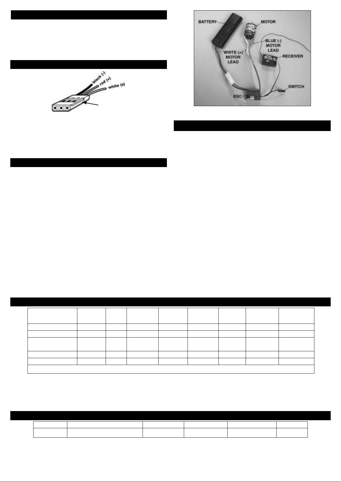
STEP 1: MOUNTING THE ESC & RECEIVER
The following information can help the ESC perform at maximum ef ficiency
and minimize the chance of overheating and radio interference problems.
MOUNTING THE ESC (Figure 1)
1. Locate the ESC in a position to allow for good airflow, with as little
obstruction from the model’s outer body or exterior dirt and debris as
possible.
Maintaining a clean ESC and achieving good airflow through the heat sink
fins is very important to keeping the ESC cool and maximizing performance.
2. Mount the ESC using double-sided mounting tape.
3. Mount the ON/OFF switch in a convenient place. Ensure that it is securely
mounted, using mounting tape or screws in a location where it cannot be
easily turned off by objects on the track or rough terrain.
MOUNTING THE RX
1. Radio interference can cause the ESC to rapidly switch between forward and
brake, overheating the transistors and possibly damaging the ESC. The Rx
and its antenna should be mounted as far away from the ESC as possible.
Also, try to keep the Rx away from the motor, battery, power wires, servos,
or any large piece of metal - such as a metal chassis.
2. Make sure the Rx antenna can be fully extended through a mast and not
completely enclosed inside the model. Do NOT cut or coil the Rx antenna.
3. Mounting the Rx deep within the tub of the chassis can greatly increase the
chance for radio interference. Try to mount the Rx away from the bottom of
the chassis tub.
4. Graphite and metal chassis transmit radio noise generated by the motor. To
mount the Rx on a graphite chassis (if necessary), place it on edge with the
crystal and antenna as far away from the chassis as possible to reduce the
chance of radio interference.
Mount the speed
control to obtain
maximum parallel
airflow THROUGH
the heat sink. For
off-road cars, or
cars with a metal or
graphite chassis,
mount the ESC on
the chassis, and the
Rx and antenna on
the rear shock tower
to reduce radio
interference.
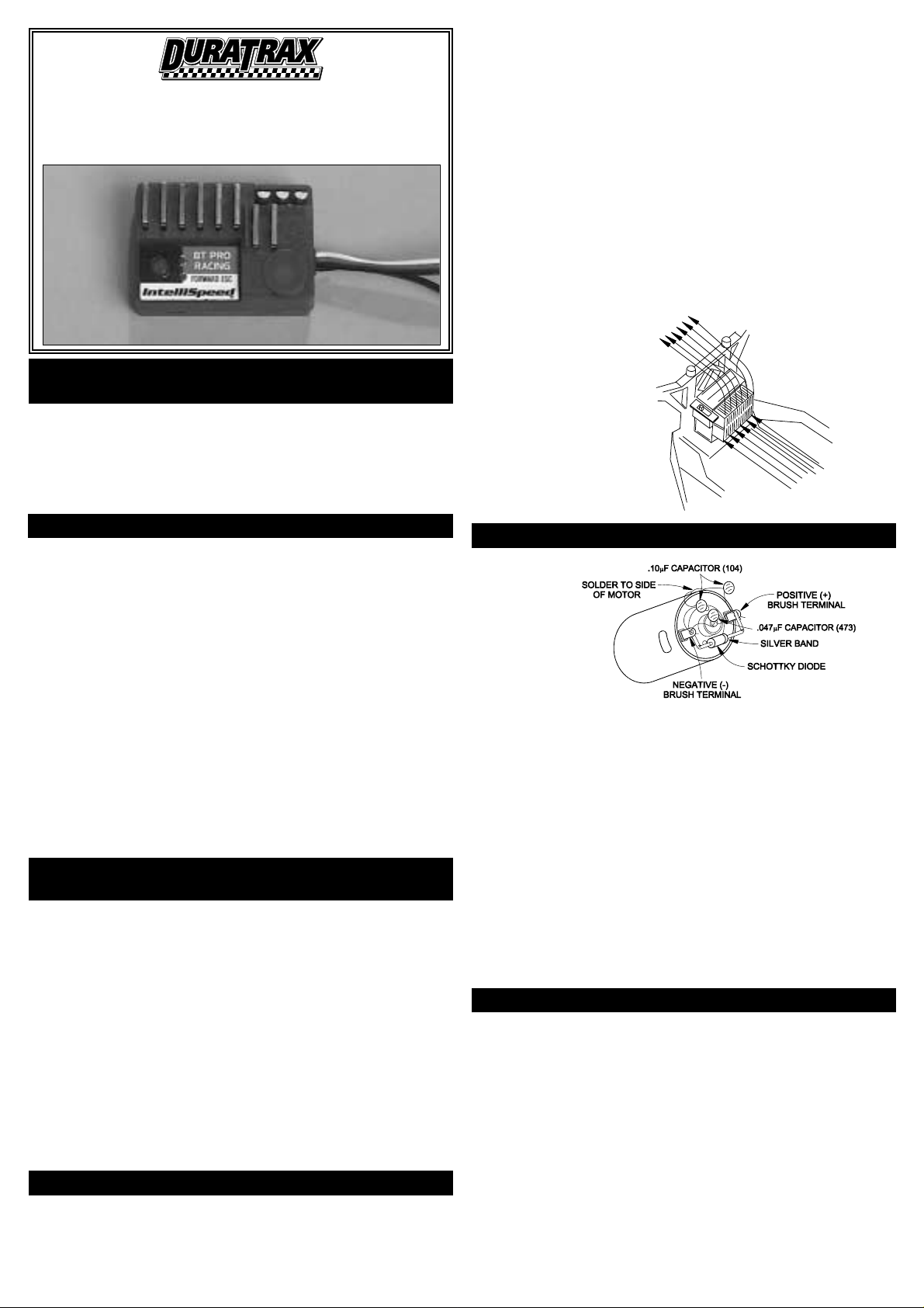
STEP 2: MOTOR & CAPACITOR CONNECTIONS
Motors generate radio noise which can interfere with your Rx and cause
problems. Check your motor to see if it has capacitors installed on it. Some
motors have capacitors built in so refer to the motor’s instructions. If the motor
does not have capacitors installed, you might need to install the three included
0.1µF, 50V non-polarized ceramic capacitors onto the motor. These capacitors
will help reduce radio noise generated by the motor and prevent possible
damage to the speed control. A Schottky diode (included) should also be
soldered across the positive and negative brush tabs on the motor to help
reduce negative effects caused by noise. Install the diode and capacitors as
follows:
• Solder one capacitor between the motor’s POSITIVE (+) brush tab and
GROUND tab†.
• Solder one capacitor between the motor’s NEGATIVE (-) brush tab and
GROUND tab†.
• Solder one capacitor between the motor’s POSITIVE (+) and NEGATIVE (-) tabs.
• Solder the Schottky diode between the motor’s positive and negative brush
tabs. Make sure the end of the Schottky diode with the colored band is
connected to the motor’s POSITIVE (+) terminal.
† Solder to the can of the motor if your motor doesn’t have a ground tab.
Figure 2
Figure 1
STEP 3: FET SERVO CONNECTION
This ESC includes an extra output power connection for high voltage FET servos.
This connection provides a regulated 7.2V supply of power that should ONLY be used
with FET servos (consult your servo manufacturer if you are unsure if your servo is
compatible). Do NOT attempt to connect a non-FET servo to this connection.
1. To help maintain glitch-free servo control, an inductor coil should be inserted
between the black FET servo output power connection on the ESC and the input
power lead on the FET servo (consult the FET servo manufacturer’s instructions
for wiring information). Inductor coils are typically specified and included with the
FET servo from its manufacturer, and thus not included with this ESC.
2. Cut both ends on the inductor coil until each is approximately 1/4" long.
3. Cut a section of shrink tubing (included) which is long enough to cover the entire
length of the coil and its connections, and slide it over the FET wire on the ESC.
4. Solder one lead of the inductor coil to the short black wire exiting the side of
the ESC.
5. Solder the other end of the inductor coil to the extra wire exiting the FET servo.
6. Slide the shrink tubing over all electrical connections. Apply heat to the tubing
using a heat gun or miniature torch to shrink it tightly in place. CAUTION: do not
place the shrink tubing or any wires directly into a flame, as it could result in
permanent damage to the shrink tubing, diode, and wires.
• Do not run the car near water! Never allow water, moisture, or any foreign
material onto the ESC’s PC board.
• Do not allow metal/conductive materials to accidentally make contact across
all motor/battery posts.
• Never use more than 7 cells (8.4 volts total) in the battery pack.
• Do not attempt to connect the battery pack to the ESC in reverse, as
permanent damage could result.
• Do not mix instructions. If you are building a vehicle that has a mechanical
speed control, do not use the wiring diagram included with the vehicle.
• Never cut or splice the ESC input wires. Do not connect a battery to the
receiver’s (Rx) “battery” slot. The Rx receives power through the ESC itself,
which plugs into the Rx’s throttle channel slot.
• Three 0.1µF, 50V monolithic capacitors (included) and a Schottky diode
(included) should be properly installed on this motor to reduce interference
from electronic noise. (See step 2)
• Always disconnect the battery pack from the ESC when not in use.
• Never turn on the ESC before plugging it into the Rx and switching on the
transmitter (Tx).
• Be careful not to touch the heat sink during use as it can become very hot.
• For the best performance, use an FM radio system.
IMPORTANT INSTRUCTIONS
(ESC=ELECTRONIC SPEED CONTROL)
™
Air Flow
Page 2
STEP 6: BASIC SPEED CONTROL SET -UP
AUTOMATIC TRACK SET -UP SETTINGS
FACTORY DEFAULT SETTINGS
STEP 7: TRACK SET -UP MODE
Before you begin this step, the ESC should be plugged into the Rx, the Tx
should already be adjusted, and the ESC switch should be in the off position.
1) Connect the battery pack to the speed control, turn on the Tx, then the ESC.
2) NEUTRAL POINT: Leave the throttle trigger in the neutral position. Press and
hold the ESC’s pushbutton until the green LED begins to flash. Then, release
the button.
3) FULL THROTTLE: Move the throttle trigger to full throttle and hold until the
red LED illuminates.
4) FULL BRAKE: Move the throttle trigger to full brake and hold until both the
red and green LEDs illuminate.
5) AUTO-BRAKE: Return the throttle trigger to neutral. The red and green
LEDs will oscillate after about 3 seconds. The Auto-Brake function causes
the ESC to automatically go to the minimum brake setting anytime the
throttle trigger is returned from forward to neutral position. This can be
especially useful when approaching corners, or on very curvy race tracks.
a. To activate auto-brakes: Move the throttle trigger to either full throttle or
full reverse (while the LEDs are oscillating), then return to neutral. The
red LED will flash. Note: The default minimum brake setting will be 0%.
To adjust this setting, see the Track Set-Up Mode instructions (see Step
7).
b. To de-activate auto-brakes: Do NOT move the throttle trigger (leave in
neutral position) when the LEDs oscillate in this step.
6) The ESC is now set for operation, confirmed by the green LED remaining on.
7) If the motor operates in reverse when applying forward throttle, the throttle
reversing switch on the Tx must be moved to the opposite position.
Track Set-up functions can be set automatically or manually.
AUTOMATIC TRACK SET-UP:
Four different automatic settings are available; where the individual functions
are pre-set to default levels for each setting. Automatic settings are available
for 1/12th scale on-road applications, stock touring car, modified touring car,
and off-road applications.
1) Press and hold the pushbutton for 4 seconds until the red LED illuminates.
2) Review “Automatic Track Set-Up Settings” (below) and determine which
setting will best suit your application.
3) Scroll up and down through this mode by momentarily moving - or stepping
- the Tx throttle trigger to full throttle (step forward) or full brake (step
backwards). The red LED will indicate the selected setting.
4) Stepping the throttle trigger four times to full forward, for example, will
select the “Off-road” setting, confirmed by four flashes of the red LED.
Accidentally passing the desired selection can easily be corrected by
stepping the throttle trigger to full reverse, scrolling the ESC backwards
through the setting options. For example, to return to the “Stock Touring
Car” setting from the “Off-road” setting, simply deflect the throttle trigger to
full reverse two times, where the red LED will now flash twice.
5) Press the ESC’s pushbutton once after selecting the track setting to confirm
set-up and to exit this mode, confirmed by illumination of both the red and
green LED’s. Note: Selecting the “Manual” setting will allow each of the
different track set-up functions to be custom set to user preferences. Proceed
to “Manual Track Set-up” below to manually set for track conditions.
By simply clipping off the tab on the side of the connector using wire cutters,
it can be directly connected to any Futaba
®
J, Airtronics “Z,” Hitec “S,” or JR
receiver. For proper connection refer to your radio’s manual. WARNING: This
connector is NOT directly compatible with the old Airtronics connector style.
For old Airtronics radios, it is highly recommended to use an Airtronics Servo
Adapter to connect this ESC to the older style Airtronics radios. NEVER
ALLOW THE RED (+) AND BLACK (-) WIRES TO CROSS ON ANY RECEIVER
OR ESC AS PERMANENT DAMAGE WILL RESULT TO BOTH ITEMS.
Adjusting your Tx is critical for proper ESC operation. The Tx throttle
adjustments are described below:
• ATV, EPA, or ATL: set all to maximum.
• Throttle trims and sub-trims: set all at neutral or zero.
STEP 4: TRANSMITTER ADJUSTMENTS
STEP 5: RADIO CONNECTOR POLARITIES
Clip tab
Application Green Red Turbo Current Brake Brake Quick Variable
LED LED Limit Min. Max. Start Freq.
1/12 On-road o x 1 sec 40A 0% 40% OFF 15620 Hz
Stock Touring Car o xx 0 sec. 100A 20% 80% ON 3900 Hz
Modified Touring o xxx 0.24 sec. 80A 10% 60% ON 7810 Hz
Car
Off-road o xxxx 0.54 sec. 60A 10% 100% ON 7810 Hz
Manual o xxxxx see below see below see below see below see below see below
o = LED off x = LED flashing
Turbo Current Limit Brake Min. Brake Max. Quick Start Freq.
Off 20A 0% 100% Off 3900 Hz
MANUAL TRACK SET-UP:
In the Manual Track Set-Up mode, each of the six individual functions can be custom configured as desired to match a particular application. In order to retur n
the Manual Track Set-Up mode to factory defaults (see “Factory Default Settings” chart below), press and hold the pushbutton while turning the ESC power switch
on. The pushbutton should be held for 5 seconds to complete the resetting function.
TO MANUALLY CONFIGURE EACH FUNCTION:
1) Press and hold the pushbutton for 7 seconds until the red and green LEDs illuminate.
2) Scroll through the Manual Track Set-up Mode by momentarily stepping the Tx throttle trigger to full throttle or full brake position.
3) Choose the desired function to be configured following the “Function Selection” chart on page 3.
2
Page 3

FUNCTION SELECTION
LED DISPLAY
TURBO LEVEL (DELAY IN SECONDS)
CURRENT LIMITING LEVEL (AMPS)
BRAKE MINIMUM LEVEL
BRAKE MAXIMUM LEVEL
QUICK STAR T LEVEL (LENGTH OF ACTIVATION IN SECONDS)
Function Turbo Current Limit Brake Min. Brake Max. Quick Start Freq.
Throttle steps / red 1 2 3 4 5 6
and green LED flashes
12345 6 7 8 9 1011
Off 0 sec 0.24 sec 0.54 sec 1.0 sec 1.5 sec 2.0 sec 2.5 sec 3.0 sec N/A N/A
TURBO: After full throttle has been engaged for the preset time selected from above, the Current Limiting action will be disabled. After the Turbo setting has been
selected, press the pushbutton to confirm the selection. The red and green LEDs will illuminate to indicate this setting is complete. Proceed to set another function.
Or, if all function levels are established, store the selected settings in the ESC and exit programming mode by holding the pushbutton for 4 seconds.
123 456 7 8 9 10 11
10A 20A 30A 40A 50A 60A 70A 80A 90A 100A N/A
Current Limiting: Sets maximum output current to restrict motor torque, adjustable from 10-100 amps. Set correctly, can extend battery run-time and limit wheel
spin. If the Quick Start is activated, the Current Limiting function is disabled when the vehicle is activated from a dead stop until the selected Quick Start time
has elapsed (see Quick Start Function Set-Up). If the Turbo is activated, the Current Limiting function is disabled when the vehicle has been at full throttle for
the selected Turbo delayed activation time (see Turbo Function Set-Up). After the Current Limiting setting has been selected, press the pushbutton to confirm the
selection. The red and green LEDs will illuminate to indicate this setting is complete. Proceed to set another function. Or, if all function levels are established,
store the selected settings in the ESC and exit programming mode by holding the pushbutton for 4 seconds.
Function Level: Each Function Level follows the level number chart as seen below. Follow this chart to select the proper level for each
function.
LED 1 2 3 4 5 6 7 8 9 10 11
Red • •• • • X XX XXX XXXX XXXXX XXXXXX
Green X XX XXX XXXX XXXXX
••••••
•
= LED on X = LED flashing
4) Once the appropriate function above has been selected, press the pushbutton.
5) Select the desired level or value for the chosen function, again by stepping the throttle trigger to either full forward or full reverse positions. Refer to the individual
Function Level charts below to determine the exact level desired for each function.
123456 7 8 9 10 11
0% 10% 20% 30% 40% 50% 60% 70% 80% 90% 100%
MINIMUM BRAKE: the minimum brake position, selected by the throttle stick (0-100%). After the Minimum Brake setting has been selected, press the pushbutton
to confirm the selection. The red and green LEDs will illuminate to indicate this setting is complete. Proceed to set another function. Or, if all function levels are
established, store the selected settings in the ESC and exit programming mode by holding the pushbutton for 4 seconds.
123456 7 8 9 10 11
0% 10% 20% 30% 40% 50% 60% 70% 80% 90% 100%
MAXIMUM BRAKE: the maximum brake position, selected by the throttle stick (0-100%). After the Maximum Brake setting has been selected, press the
pushbutton to confirm the selection. The red and green LEDs will illuminate to indicate this setting is complete. Proceed to set another function. Or, if all function
levels are established, store the selected settings in the ESC and exit programming mode by holding the pushbutton for 4 seconds.
12 3 4 5 6 78 9 1011
On Road Off Road 0.04 sec 0.1 sec 0.16 sec 0.2 sec 0.3 sec 0.5 sec 0.70 sec 1.0 sec N/A
QUICK START: When the Quick Start function is engaged, the Current Limiting function is disabled until the pre-set activation time has elapsed. The Quick Start
Function is similar to current limit but regulates output current only when motor begins rotation from a dead stop, for high traction / low wheel spin.
a. On-road: this function provides maximum current at the start. To activate, move the throttle trigger to full-brake before the start and hold for 10 seconds.
When applying full throttle at the start, the maximum initial current flows to the motor. As soon as the throttle stick is moved to the neutral position after the
start, this function becomes disabled.
b. Off-road: this function permits a gentle start for slippery sur faces. Activate the setting as described above, but first set the ESC for of f-road mode.
After the Quick Start setting has been selected, press the pushbutton to confirm the selection. The red and green LEDs will illuminate to indicate this setting is
complete. Proceed to set another function. Or, if all function levels are established, store the selected settings in the ESC and exit programming mode by holding
the pushbutton for 4 seconds.
3
Page 4

U.S. AND CANADA ONLY
DuraTrax warrants this product to be free from defects in materials and workmanship for a period of 120 days from the date of purchase. During that period, we
will repair or replace, at our option, any product that does not meet these standards. You will be required to provide proof of purchase date (receipt or invoice).
If, during the 120-day period, your DuraTrax product shows defects caused by abuse, misuse, or accident, it will be repaired or replaced at our option, at a service
charge not greater than 50% of the current retail list price. Be sure to include your daytime telephone number in case we need to contact you about your repair.
This warranty does not cover components worn by use, application of reverse voltage, cross connections, poor installation, subjection of components to foreign
materials, any alterations to wires, or tampering. In no case shall our liability exceed the original cost of the product.
Your warranty is voided if...
A. Reverse voltage is applied to the ESC by connecting the battery pack backwards, or plugging the motor connectors into the battery pack.
B. Any wires are allowed to become frayed which could cause a short.
C. The ESC is subjected to improper voltage on the inputs.
D. Tampering of any electronic components or circuitry is attempted.
E. Water, moisture, or any other for eign material is allowed inside the ESC.
F. The red wire in the input harness is not removed when using an external battery pack.
G. Too much pressure is applied when installing the heat sink.
Under no circumstances will the purchaser be entitled to consequential or incidental damages. This warranty gives you specific legal rights, and you may also have
other rights which vary from state to state. If you attempt to disassemble or repair this unit yourself it may void the warranty.
For service to your DuraTrax product, either in or out of warranty, send it post paid and insured to:
HOBBY SERVICES
1610 Interstate Drive,
Champaign, IL 61822
(217) 398-0007
E-Mail: hobbyservices@hobbico.com
Internet Address: www.duratrax.com
12 3 4567891011
244Hz 976Hz 1950Hz 3900Hz 7800Hz 15600 Hz N/A N/A N/A N/A N/A
VARIABLE PULSE FREQUENCY: the output pulse frequency is adjustable. Higher frequencies create smoother response, cooler operation, and maximize battery
capacity and run-time. Lower frequencies create less-smooth response, higher operating temperatures, but deliver more raw power to the motor. After the
Frequency setting has been selected, press the pushbutton to confirm the selection. The red and green LEDs will illuminate to indicate this setting is complete.
Proceed to set another function. Or, if all function levels are established, store the selected settings in the ESC and exit programming mode by holding the
pushbutton for 4 seconds.
Note: ESCs that operate normally when received will be charged a minimum service fee and retur n shipping charges. Before sending your ESC in for service, it is
important that you review the Troubleshooting Guide in this instruction sheet. The ESC may appear to have failed when other problems exist in the system, such
as a defective transmitter, receiver or servo, or incorrect adjustments/installation.
• Hobby dealers are not authorized to replace speed controls thought to be
defective.
• Do not cut the input harness, switch harness, or power wires of the speed control before sending it for service. A fee will be charged for cut wires which must be
replaced for testing.
SPEED CONTROL DOES NOT WORK
Problem: Motor and/or steering servo are dead.
1) Recharge dead batteries.
2) Check for faulty power connections.
3) Check for a damaged connection between ESC and receiver.
4) Reverse polarity at battery. Allow ESC to rest at least 1 minute to reset the circuit
protection system.
5) Internal damage. Unit may require service. See “Service Procedures.”
Problem: Case is melted.
Internal damage and unit may require service. See “Service Procedures.”
Problem: ESC runs with switch off.
Drive transistor may be blown and unit may require service. See “Service Procedures.”
SPEED CONTROL WORKS BUT OTHER PROBLEMS EXIST
Problem: Receiver glitches or stutters during acceleration.
1) The three required motor capacitors and Schottky diode are not installed or have broken.
Re-check the diode and all caps.
2) The Rx signal is intermittent due to a large voltage dr op during acceleration. Use an
external battery and a non-BEC receiver designed to be used with ESCs. Remove the red
lead from the ESC to RX wiring harness prior to powering up the RX and ESC.
3) Rx mounted too close to ESC causing interference. Re-locate Rx away from
ESC.
4) Check for faulty power connections.
5) Use of an AM radio system might be resulting in erratic signals. Use of an FM radio system
might be necessary.
Problem: Model runs slowly or has no acceleration.
1) The ESC is not set up properly. Repeat Step 5 above.
2) Check for faulty battery and/or motor connections.
3) Tx is improperly adjusted. Repeat Step 3 above.
Problem: Steering servo works but motor is dead.
1) Motor brushes are hanging up, worn out, or motor is bad. Clean or replace brushes and
check motor.
2) Check for faulty motor connections.
Problem: Overheated motor or hot power plugs.
1) Motor is geared too high. Change to a lower gear setup.
2) Binding in the vehicle’s drivetrain. Check to make sure nothing is interfering with the
models’ drive-train.
3) The motor is shorted electrically. Check the motor for shorts and replace if necessary.
4) Check for faulty motor connections.
Problem: Motor runs backwards while forward LEDs are on.
1) Motor is wired backwards. Re-check Step 6 above.
2) A “reverse rotation” motor is being used. Replace with a forward rotation motor.
Problem: Motor runs backwards when forward command is given, even though LEDs
match the motor direction.
Move the Tx throttle-reversing switch to the opposite position.
Problem: Model runs properly, and then motor goes dead.
The built-in thermal protection may be automatically shutting down power to the ESC due
to overheating conditions. Check for binding drivetrain, bad motor or incorrect gear ratio for
track conditions. Adjust gear mesh, replace motor or change gear ratio. The ESC should
reset in a few minutes and operation can again be attempted.
TROUBLESHOOTING GUIDE
SERVICE PROCEDURES
120-DAY LIMITED WARRANTY
© Copyright 2002 V1.0 DTXZ0005 For DTXM1080
OPERATING FREQUENCY LEVEL (IN HZ)
 Loading...