

Duke TBIL-LR-131 Service Manual
TACO BELL
I-LINE
COUNTER
Service Manual
Please read this manual completely before attempting
to install, operate or service this equipment
This document is prepared for trained Duke service technicians. It is not to be used by anyone not
properly qualied to perform these procedures.
This Service Manual is not all encompassing. If you have not been trained on servicing this product,
be sure to read the manual completely before attempting servicing. Be sure all necessary tools, test
equipment, and skills are available. Those procedures for which you do not have the proper skills
and test equipment must be performed only by a qualied Duke trained service technician.
This manual is copyright ©2011 Duke Manufacturing Company. All rights reserved. Reproduction without
written permission is prohibited. Duke is a registered trademark of the Duke Manufacturing Company.
Duke Manufacturing Company
2305 N. Broadway • St. Louis, MO 63102
800.735.3853 • 314.231.1130
Fax: 314-231-5074
www.dukemfg.com
P/N 219208B
Service Manual for Taco Bell I-Line Counters
IMPORTANT WARNING AND SAFETY INFORMATION
WARNING
READ THIS MANUAL THOROUGHLY BEFORE OPERATING, INSTALLING, OR
PERFORMING MAINTENANCE ON THE EQUIPMENT.
WARNING
FAILURE TO FOLLOW INSTRUCTIONS IN THIS MANUAL CAN CAUSE PROPERTY
DAMAGE, INJURY OR DEATH.
WARNING
DO NOT STORE OR USE GASOLINE OR OTHER FLAMMABLE VAPORS OR
LIQUIDS IN THE VICINITY OF THIS OR ANY OTHER APPLIANCE.
WARNING
DO NOT OPERATE THIS EQUIPMENT WITHOUT PROPERLY PLACING AND
SECURING ALL COVER AND ACCESS PANELS.
CAUTION
Observe the following:
• Provide and maintain adequate minimum clearances from all walls and combustible materials.
• Provide and maintain adequate clearance for air openings.
• Keep the equipment area free and clear of combustible material.
• Operate equipment only on the type of electricity indicated on the specication plate.
• Retain this manual for future reference.
2

Service Manual for Taco Bell I-Line Counters
TABLE OF CONTENTS
TACO BELL I-LINE COUNTER SPECIFICATIONS .........................................................4
INSTALLATION ................................................................................................................4
LOCATION..................................................................................................................4
LEVELING ..................................................................................................................4
STABILIZING ..............................................................................................................4
ELECTRICAL CONNECTION ....................................................................................4
PARTS REMOVAL AND REPLACEMENT PROCEDURES .............................................5
MAIN CONTROL PANEL ............................................................................................ 5
Dry Channel Control Display ................................................................................5
Control Panel ON/OFF switches ...........................................................................5
DRY CHANNEL ......................................................................................................... 6
General .................................................................................................................6
Relay Box .............................................................................................................6
Relay Box Components ........................................................................................7
Solid State Relay (SSR) Replacement ................................................................. 7
Transformer Replacement ....................................................................................8
Channel Assembly ................................................................................................8
TRI-CHANNEL COLD PAN ........................................................................................9
Evaporator ............................................................................................................ 9
Thermostat ............................................................................................................9
Tri-Channel Compressor Assembly ....................................................................10
Condenser Cooling Fan ...................................................................................... 11
REFRIGERATED BASE UNIT (RBC) ....................................................................... 11
Evaporator Fan Assembly ................................................................................... 11
RBC Thermostat .................................................................................................12
RBC Refrigeration System .................................................................................. 13
RBC Door Gaskets ............................................................................................. 13
RBC Door Adjustment .........................................................................................13
RECHARGING REFRIGERATION SYSTEM .................................................................14
TOOLS......................................................................................................................14
DUKE SERVICE BULLETIN NUMBER 26 –
REFRIGERATION SYSTEM EVACUATION .......................................................14
DUKE SERVICE BULLETIN NUMBER 35 –
ACCESSING SEALED REFRIGERATION SYSTEMS ....................................... 14
LOAD CENTER ........................................................................................................15
Circuit Breaker Replacement ..............................................................................15
SERVICE INFORMATION .............................................................................................. 16
MAINTENANCE .......................................................................................................16
Stainless Steel Care and Cleaning .....................................................................16
Compressor Air Filter Care and Cleaning ........................................................... 16
TROUBLESHOOTING GUIDE .......................................................................................18
SCHEMATICS ................................................................................................................20
3

Service Manual for Taco Bell I-Line Counters
TACO BELL I-LINE COUNTER SPECIFICATIONS
MODEL DESCRIPTION VOLTAGE SIZE
TBIL-RL-131 I-Line Counter Right to Left 208 VAC 3 Phase L:1313
TBIL-LR-131 I-Line Counter Left to Right 208 VAC 3 Phase L:1313
INSTALLATION
LOCATION
The I-Line Counter is intended for indoor use only.
Be sure the chosen location has a oor strong
enough to support the total weight of the unit fully
loaded with food product. Reinforce the oor, if
necessary, to provide for maximum loading. For
the most efcient operation, be sure to provide
good air circulation.
LEVELING
Be sure the unit is placed on a rm, at surface/
oor. Check for cracks in ooring or tile and avoid
these areas if possible. If necessary, place support
pads, properly rated for the weight of the unit, to
“bridge” uneven or cracked ooring. Level the unit
accordingly using the leg adjusters.
STABILIZING
Use the leg adjustments to ensure that the unit
is solid to the oor surface at all contact points.
Ensure that the unit does not “rock” when pressure
is applied to the top corners.
ELECTRICAL CONNECTION
The I-Line Counter Unit requires 208VAC,
3 Phase, 50/60 Hz. Direct wiring I-Line Counter
Unit to the power supply must be performed by
a certied electrician and must comply with local
electrical codes for your municipality.
4

Service Manual for Taco Bell I-Line Counters
TRI
CHANNEL
TACO
TOWER
TORTILLA
GRILL
DRY
CHANNEL
PROG
Control
Display
TRI
CHANNEL
TACO
TOWER
TORTILLA
GRILL
DRY
CHANNEL
PROG
Mounting
Screws
TRI
CHANNEL
TACO
TOWER
TORTILLA
GRILL
DRY
CHANNEL
PROG
Control
Switch
Panel
1
2
3
4
PARTS REMOVAL AND REPLACEMENT PROCEDURES
MAIN CONTROL PANEL
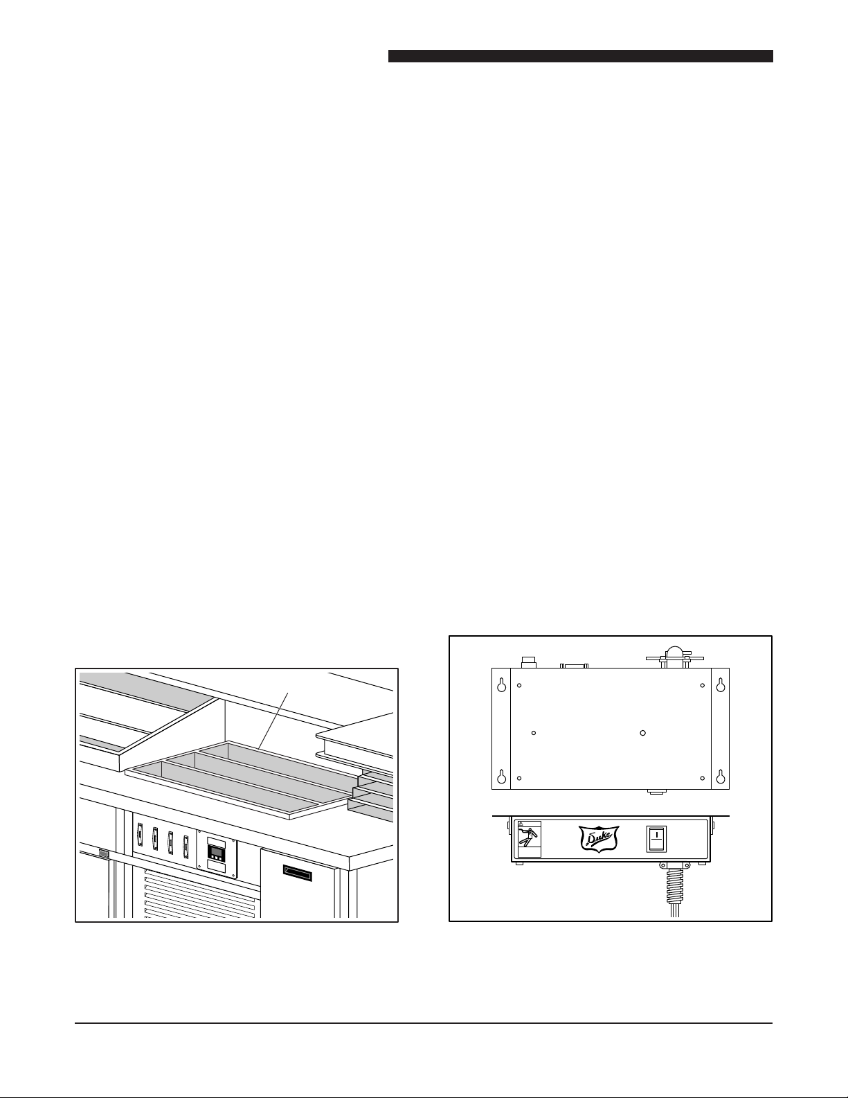
Dry Channel Control Display
Figure 1. Location of Dry Channel
Control Display
The Dry Channel Control Display is located on
the operator’s side of the I-Line Counter next to
the power switches.
4. Remove the four Dry Channel Control Display
Board mounting screws.
5. Remove the Dry Channel Control Display
Board through the front of the control panel.
6. Install the new Dry Channel Control Display
Board, reattach mounting screws.
7. Refer to the wire tags, and reconnect all wire
harnesses.
8. Place the Main Power ON/OFF switch in the
ON position.
9. Place Dry Channel power switch in ON
position.
10. Wait a minimum of 20 minutes. Monitor Dry
Channel Control Display Board for proper
operation.
Control Panel ON/OFF switches
1. Place the Main Power ON/OFF switch in the
OFF position. Use proper Lockout/Tagout
procedures.
2. Lift control panel up and tilt it out.
Figure 2. Control Panel in open position.
3. Tag and unplug Dry Channel Control Display
Board wiring.
Figure 3. Control Switch Panel
1: Tr i -Channe l C o ld Pan (120VAC ,
Single Phase, 948W)
2: Taco Tower Infrared Heaters and Lights
(120VAC, Single Phase, 1840W)
3: Tortilla Gril l (2 08VAC, 3 Phase,
1200W)
4: Dry Ch a n n e l Warmer ( 2 0 8 VAC ,
3 Phase, 2100W)
5
Service Manual for Taco Bell I-Line Counters
Dry Channel Unit
POWER
O
ON
OFF
DANGER
The four switches on the control panel are
labeled Cold Pan, Taco Tower, Tortilla Grill and
Dry Channel.
1. Place the Main Power ON/OFF switch in the
OFF position. Use proper Lockout/Tagout
procedures.
2. Open the switch panel.
3. Remove the protective cover from the back of
the switches.
4. Tag and disconnect the wires from the suspect
switch.
5. Test the switch for continuity; it should read 0
ohms in the ON Position. Replace it if it reads
open or a high resistance.
6. Remove two screws on front of control panel
to remove faulty switch.
7. Replace switch with properly rated switch.
8. Refer to tags, and reconnect wires.
9. Install protective cover.
The Dry Channel unit is mounted above the
compressor units. The Dry Channel unit must be
removed from the I-Line Counter in order to service
a channel assembly or the relay box.
1. Place Main Power ON/OFF switch in the
OFF position. Use proper Lockout/Tagout
procedures.
2. Open the I-Line Counter Control Panel
3. Tag and unplug the Dry Channel cables from
the Dry Channel Control Display.
4. Tag and disconnect Dry Channel power
cord.
5. Remove the hardware that holds the Dry
Channel unit in place in the I-Line Counter.
6. Carefully lift the Dry Channel unit free of
the I-Line Counter: Do not damage the Dry
Channel’s cabling or power cord.
7. Reverse this procedure to reinstall the Dry
Channel unit after servicing it or to install a
replacement unit.
10. Close control panel.
11. Restore I-Line Counter to service and check
for proper switch operation.
DRY CHANNEL
General
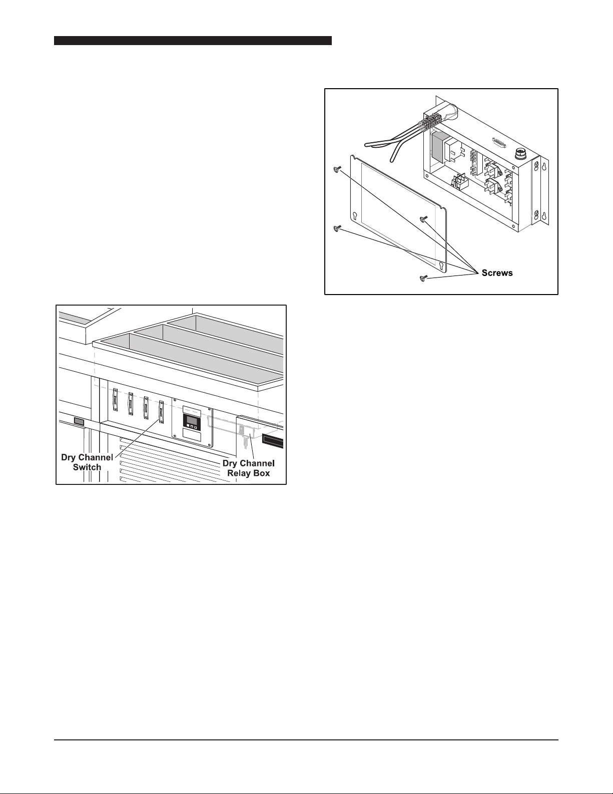
Relay Box
Note: The following procedures are performed
while the Dry Channel unit is removed from the
I-Line Counter.
Figure 4. Location of the Dry Channel Unit
6
Figure 5. Dry Channel Relay Box
Service Manual for Taco Bell I-Line Counters
ON
OFF
O
TRI
CHANNEL
TACO
TOWER
TORTILLA
GRILL
DRY
CHANNEL
PROG
The Dry Channel Relay Box is mounted on
the bottom of the Dry Channel Tub assembly.
Typically, it is on the side of the Dry Channel unit
that faces the front of the I-Line Counter on the
right side. Under normal circumstances, it is not
necessary to replace the Dry Channel Relay Box
in its entirety.
Note: The Power ON/OFF switch mounted on
the Dry Channel Relay Box unit must remain in the
ON position at all times. The operator is not able
to access this switch once the Dry Channel unit is
mounted in the I-Line Counter. The Dry Channel
unit is turned ON and OFF using the 4th ON/OFF
switch on the Control Panel. Refer to the Control
Panel section of this manual for instructions on
replacing the Control Panel ON/OFF switches.
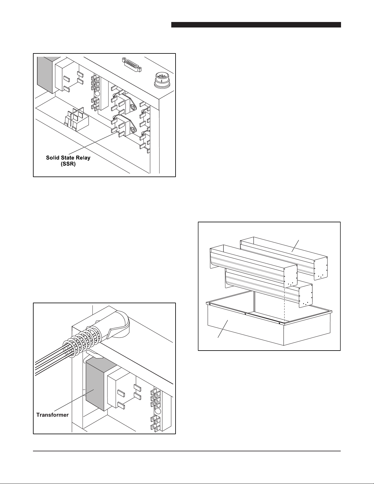
Relay Box Components
Figure 7. Relay Box with cover removed
Remove the four screws holding the Dry Channel
Relay Box cover in place.
Figure 6. Location of Operator ON/OFF
Switch – Dry Channel Unit
7
Service Manual for Taco Bell I-Line Counters
Tub
Channel
Assembly
Solid State Relay (SSR) Replacement
Figure 8. Solid State Relay (SSR)
The I-Line Counter uses Dry Channel Model HDC3
Components. There are 6 Solid State Relays in
the this unit. Test each relay to determine which
one is causing the fault.
Figure 9. 24Volt Step Down Transformer
The step down transformer utilizes a tapped
primary the allows the Dry Channel unit to be
operated at either 208VAC or 240VAC.
1. Tag and disconnect the primary power cord
from the transformer; also tag the terminals
on the transformer to ensure the power cord
will be connected at the correct voltage for the
I-Line Counter.
2. Tag and disconnect wires to the secondary.
3. Remove four nuts attaching transformer
to the studs in the Relay Box and remove
Transformer.
4. Reverse procedure to install a new Transformer.
Ensure that the power cable is connected to the
correct terminals on the transformer to math
the operating voltage of the I-Line Counter.
Channel Assembly
1. Label and disconnect wires from SSR to be
replaced.
2. Remove two screws attaching SSR to Relay
Box and remove SSR.
3. Reverse procedure to install a new SSR.
Transformer Replacement
Figure 10. Dry Channel HDC3 Tub and
Channel Assembly
The Heat Elements, Hi-Limit Thermostats and
RTDs are imbedded in a foil wrap that is attached
to the bottom of each Channel Assembly. These
parts are not serviceable in the eld. The entire
Channel Assembly must be replaced in the event
of a failure of any of these components.
8
 Loading...