

Duke SWFM Installation Manual
WATER
WASH
VENTILATOR
OWNER’S
MANUAL
BY
Please read this manual completely before attempting to install,
operate or service this equipment.
This manual is Copyright © 2010 Duke Manufacturing Co. All rights reserved.
Reproduction without written permission is prohibited. Duke is a registered
trademark of the Duke Manufacturing Co.
Southern Engineering
A Division of Duke Manufacturing Co.
2305 N. Broadway
St. Louis, MO 63102
Phone: 314-231-1130
Toll Free: 1-800-735-3853
Fax: 314-231-5074
www.dukemfg.com
P/N 0058619

Water Wash Ventilator Owner’s Manual
IMPORTANT WARNING AND SAFETY INFORMATION
POST IN A PROMINENT LOCATION instructions to be followed in
the event the user smells gas. This information shall be obtained by
consulting the local gas supplier.
FOR YOUR SAFETY:
Do not store or use gasoline or other ammable vapors or liquids in the
vicinity of this or any other appliance.
WARNING: Improper installation, adjustment, alteration, service or
maintenance can cause property damage, injury or death. Read the
installation, operating and maintenance instructions thoroughly before
installing or servicing this equipment.
INSTALLATION INSTRUCTIONS
• Units shall be installed by qualied personnel in accordance with all
local and municipal codes.
• Wiring Diagrams are provided with equipment as supplied.
• Exhaust and supply air ow rates shall be in accordance with
NFPA96-UL requirements.
• Exhaust and supply (if provided) air ow rates were established
under controlled laboratory conditions, and greater and/or lesser air
supply may be required for complete vapor and smoke removal in
specic installations.
THIS MANUAL MUST BE RETAINED FOR FUTURE REFERENCE
2

Water Wash Ventilator Owner’s Manual
TABLE OF CONTENTS
LIMITED WARRANTY .........................................................................................................................5
OWNER’S REGISTRATION REFERENCE SHEET ............................................................................6
INSTALLER: FILL OUT THIS FORM, DETACH AND PUT WITH THE
START-UP REPORT TO BE SENT TO SOUTHERN ENGINEERING ................................................7
GENERAL INFORMATION ..................................................................................................................9
PRINCIPLES OF OPERATION ...........................................................................................................9
CONTAMINANT CAPTURE ........................................................................................................9
GREASE EXTRACTION .............................................................................................................9
AUTOMATIC CLEANING ..........................................................................................................10
FIRE PROTECTION CYCLE .....................................................................................................11
Standard Push Button Control ........................................................................................... 11
SEQUENCE OF OPERATION ..........................................................................................................12
STANDARD CONTROL PANEL ................................................................................................12
Wash Cycle Procedure ......................................................................................................12
Fan Cycle ...........................................................................................................................12
MODE COMMANDER ...............................................................................................................13
FIRE SUPPRESSION SYSTEMS .....................................................................................................13
APPLIANCE PROTECTION ......................................................................................................13
DRY AND WET CHEMICAL SYSTEMS ....................................................................................13
WATER FOG SYSTEM .............................................................................................................14
WATER WASH FIRE SUPPRESSION ......................................................................................14
COMPONENT IDENTIFICATION AND ACCESS ..............................................................................16
STANDARD CONTROL CABINET ...........................................................................................16
Push Button Control ...........................................................................................................16
ELECTRICAL COMPARTMENT ................................................................................................17
PLUMBING COMPARTMENT ...................................................................................................19
EXTERNALLY MOUNTED COMPONENTS .....................................................................................22
VENTILATOR MOUNTED COMPONENTS AND ACCESS PANELS ...............................................23
WATER WASH MAINTENANCE PROCEDURES .............................................................................26
DETERGENT SYSTEM .............................................................................................................26
Water Wash Detergent Pump Replacement ......................................................................26
Start-up of the Detergent Pump Assembly ........................................................................28
Care and Adjustments .......................................................................................................28
Gaskets and Check Valves ................................................................................................29
Detergent Reservoir ...........................................................................................................29
3

Water Wash Ventilator Owner’s Manual
Service and Repairs ..........................................................................................................30
Pump Head Assembly or Diaphragm .................................................................................30
Ball Check and Valve Seat Replacement ..........................................................................31
Approved Detergents .........................................................................................................31
Water Wash Hood Detergent/Water Consumption Chart ..................................................32
EXTERNALLY MOUNTED COMPONENTS .....................................................................................33
REMOTE FIRE PULL ................................................................................................................33
VACUUM BREAKER .................................................................................................................33
WASH SOLENOID VALVES ......................................................................................................34
DAMPER MOTOR .....................................................................................................................35
WASH NOZZLES ......................................................................................................................35
TROUBLESHOOTING ......................................................................................................................36
WIRING SCHEMATICS .....................................................................................................................41
MODE COMMANDER FOR ONE VENTILATOR ......................................................................41
MODE COMMANDER FOR TWO VENTILATORS ...................................................................42
MODE COMMANDER FOR THREE VENTILATORS ...............................................................43
MODE COMMANDER FOR FOUR VENTILATORS .................................................................44
STANDARD WIRING DIAGRAM FOR VENTILATOR (OLD STYLE) ........................................46
PREVENTIVE MAINTENANCE CHART ...........................................................................................47
SERVICE AND ORDERING INFORMATION ....................................................................................48
WATER WASH VENTILATOR REPLACEMENT PARTS LIST ..........................................................49
CUSTOMER ASSISTANCE ...............................................................................................................51
4

Water Wash Ventilator Owner’s Manual
LIMITED WARRANTY
Southern Engineering Systems products are warranted to be free from defects in material or workmanship for a period of one year
from the date of start-up or 18 months from the date of shipment (whichever comes rst) when installed, operated and serviced
in accordance with the Southern Engineering Systems recommendations, when used under normal conditions for their intended
purposes; and when evidence of such installations, proper and acceptable to Southern Engineering Systems, are recorded at the
factory. Southern Engineering Systems reserves the right to void this warranty for operations of its product outside of these terms.
Southern Engineering shall further warrant motorized conveyor drive components (consisting of motor, gear reduction unit, track
glide wear surfaces, speed controller, bearings, shaft(s)) for an additional 48 months after the expiration of the above described
one-year warranty. This additional warranty does not apply to renewable parts such as drive chains or gears, or the belting; and
is for parts replacement only if these motorized conventional conveyor drive components become inoperative due to a defect
in factory workmanship or a failure in material utilized in its original operation and maintenance instructions, labor not included.
Any request for repair or replacement must be made to the Service Department of Duke Manufacturing Co., 2305 N. Broadway,
St. Louis, MO 63102. Southern Engineering Systems’ warranty shall be limited to repair or replacement (at Duke Manufacturing
Co's. option) of any part of said equipment that proves to be defective after an examination by its Service Department or designate.
The labor required to make repairs or replacement under this warranty shall be furnished by Duke Manufacturing Co. or its
authorized representative between the hours of 8:00 AM and 400 PM Monday through Friday, and is limited to the actual repairs
or replacements of the warranty item. Labor and cost of such labor to inspect and/or determine the origin of the problem involving
the examination of equipment or systems not furnished or manufactured by Southern Engineering Systems is specically excluded.
This warranty is only for applications which the equipment was originally installed, and only covers original equipment components.
This warranty does not cover routine maintenance (such as but not limited to tightening belts, adjustment of linkage or controls,
cleaning, etc.) or replacement of renewable items such as belts, chains, detergent, lters, etc. Malfunctions caused by improper
water pressure, electrical power variances, exhaust fan performance (ventilators only), or restricted drainage systems are also
excluded from warranty protection. Warranty claims will not be honored unless the manufacturer is advised in advance of the
work being performed by an authorized and approved representative of Duke Manufacturing Co.
This warranty does not cover loss of food, other products, or other consequential damage resulting from any equipment failure.
THIS WARRANTY IS THE ONLY WARRANTY; THERE BEING NO OTHER WARRANTY EITHER EXPRESSED OR IMPLIED.
5

Water Wash Ventilator Owner’s Manual
OWNER’S REGISTRATION REFERENCE SHEET
FOR SOUTHERN ENGINEERING SYSTEMS BY DUKE WATER WASH VENTILATORS
(ll out at time of installation)
DO NOT REMOVE FROM THIS MANUAL
Model No. ______________________________ Serial No. _______________________________
Customer’s Name: _________________________________________________________________
_________________________________________________________________________________
Address: _________________________________________________________________________
Installer’s Name: __________________________________________________________________
Address: _________________________________________________________________________
Installed At: ______________________________________________________________________
Installation Date: __________________________________________________________________
Remarks: ________________________________________________________________________
_________________________________________________________________________________
_________________________________________________________________________________
6

Water Wash Ventilator Owner’s Manual
INSTALLER: FILL OUT THIS FORM, DETACH AND
PUT WITH THE START-UP REPORT TO BE SENT TO
SOUTHERN ENGINEERING
WARRANTY REGISTRATION
for
SOUTHERN ENGINEERING SYSTEMS BY DUKE WATER WASH VENTILATORS
Model No. ______________________________ Serial No. _______________________________
Customer’s Name: _________________________________________________________________
_________________________________________________________________________________
Address: _________________________________________________________________________
Installer’s Name: __________________________________________________________________
Address: _________________________________________________________________________
Installed At: ______________________________________________________________________
Installation Date: __________________________________________________________________
Remarks: ________________________________________________________________________
_________________________________________________________________________________
_________________________________________________________________________________
For Factory Use Only S/O# __________________________________________________________
_________________________________________________________________________________
_________________________________________________________________________________
7

Water Wash Ventilator Owner’s Manual
8
Water Wash Ventilator Owner’s Manual
GENERAL INFORMATION
TO E N SUR E P R OPE R O P ERATI ON AN D
MAINTENANCE OF THE SOUTHERN ENGINEERING
BY DUKE WATER WASH VENTILATION SYSTEM,
PLEASE READ AND UNDERSTAND THIS MANUAL
THOROUGHLY.
When necessary, the following information will be
indented and paraphrased.
NO T E: Infor m ation pert aining to special
instructions regarding the care and use of the
Mode Commander.
CAUTION: Information intended to indicate
situations which may cause immediate or
future damage to the Mode Commander.
WARNING: Advice against improper use or
procedures which may result in bodily injury
for which Southern Engineering will accept
no responsibility.
All information, illustrations and specications contained
in this manual are based on the latest product information
available at the time of printing. Southern Engineering
by Duke reserves the right to make changes at any
time, without notice, in specications, and models, also
to discontinue models. Southern Engineering by Duke
also reserves the right to change any specications or
parts at any time without incurring obligation to equip
the same on models manufactured prior to the date
of such change.
The continuing accuracy of this manual cannot be
guaranteed.
All illustrations used in this manual may not depict
models or equipment and are intended as representative
views for reference only.
Future supplement sheets will be added or deleted
as necessary.
Prints or system details located in this manual are for
instructional purposes only and do not represent actual
or scale drawings.
PRINCIPLES OF OPERATION
CONTAMINANT CAPTURE
The primary purpose of any kitchen ventilator system
is to take objectionable odors, grease, steam and dust
particles from the cooking surface and transfer them
to an un-objectionable area.
The two most important considerations in achieving
contaminant capture are air velocity and volume.
Because one directly affects the other, each will determine
how well the ventilator captures contaminants and will
be fully explained in a following section of this manual.
GREASE EXTRACTION
Because of environmental concerns and regulations, it
is more important than ever before to remove as much
grease and unwanted contaminants as possible from
the air stream being expelled from the system. The
Water Wash Ventilator is one of the most effective in
grease removal on the market.
This is accomplished by centrifugal force as the air is
drawn through a series of bafes and forced to make
turns during which the grease particles impinge upon the
bafe plates. The grease will remain inside the ventilator
through the duration of the normal cooking cycle.
Centrifugal Grease Extraction
9

Water Wash Ventilator Owner’s Manual
Centrifugal grease extraction is the removal of grease
and dust from the air stream by means of centrifugal
action without any removable parts, moving parts, or
continuous, wasteful water spray.
At the termination of this cycle, the equipment is shut
down, and the ventilator will automatically clean the
grease from the system. This extraction is accomplished
without the use of lter media or moving parts to clog
with grease.
Because of this type of extraction, the Water Wash
Ventilator is well suited for commercial and industrial
applications and removes grease much more efciently
than bafe or mesh lter systems.
Extraction Chamber
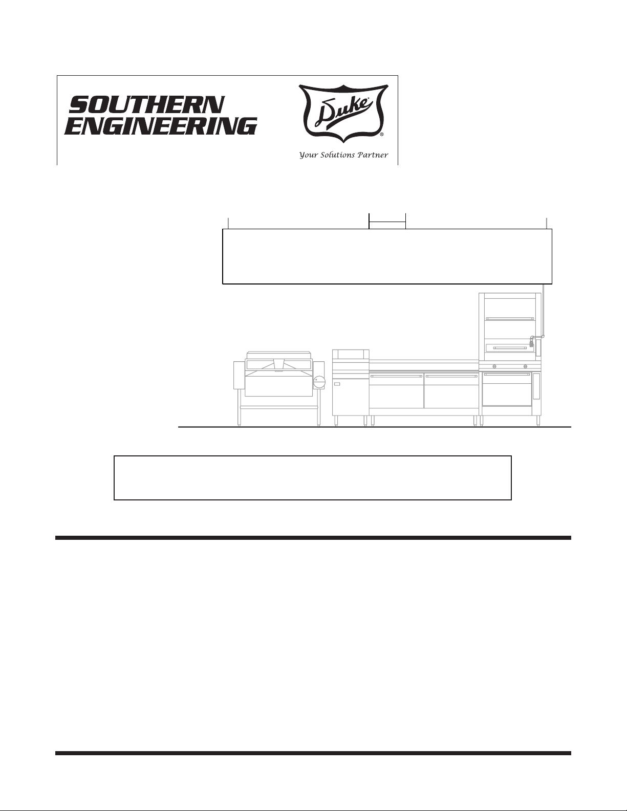
Model SWFM Hi-Velocity Wall Style Water
Wash Ventilator With “Lazy Air” Make-up
Chamber
AUTOMATIC CLEANING
The grease and dust that accumulate within the
extraction chamber during operation of the ventilator
must be removed regularly. If allowed to accumulate
for long periods of time, the grease will “bake on” to
the interior of the ventilator forming a combustible
and difcult to remove coating. To prevent this build
up, the Water Wash Ventilator features an automatic
cleaning cycle this is initiated each time the exhaust
fan is turned off, or at the preset time during which
the Water Wash Mode Commander calls for a wash
cycle. When either of this situations occur, the exhaust
fan will stop. The ventilator damper will close and the
ventilator will be sprayed with a pressurized hot water
and detergent combination. The waste water will ow
from the system into an approved plumbing drain. This
will be explained in detail in the Sequence of Operations
section of the manual.
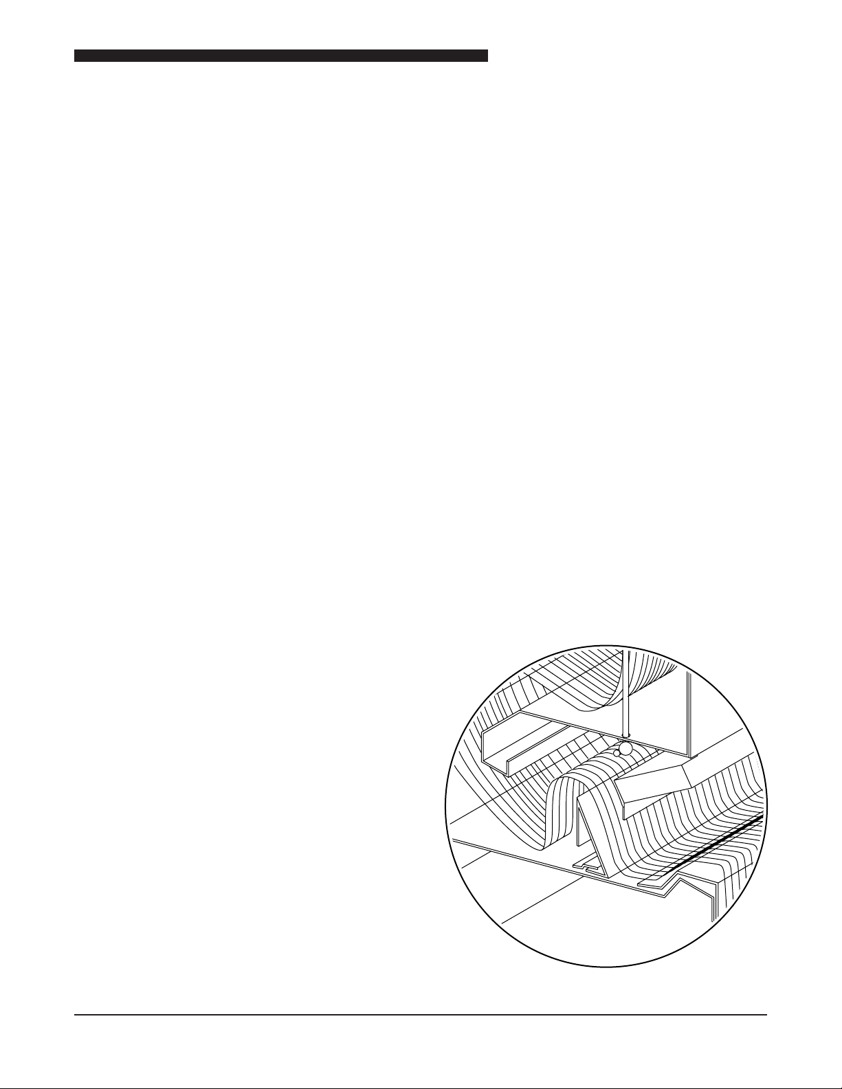
Thorough cleaning of the extraction chamber interior
is achieved by means of a pressurized hot detergent
water spray.
Spray
Nozzles
Primary
Diverter
Baffle
Southern Wash Extraction Chamber
10
Spray Manifold
Water Wash Ventilator Owner’s Manual
Cover ÊPlate
Thermostat
Mounting
Plate
J-Box
Duct
Collar
Spray Manifold
FIRE PROTECTION CYCLE
STANDARD PUSH BUTTON CONTROL
In the event of a re in the cooking area under the
ventilator, the exhaust ductwork should be protected
to prevent the exhaust fan from spreading the re to
the ductwork and the building roof. The Water Wash
Ventilator features an automatic re protection cycle to
contain res under the canopy to prevent their spread.
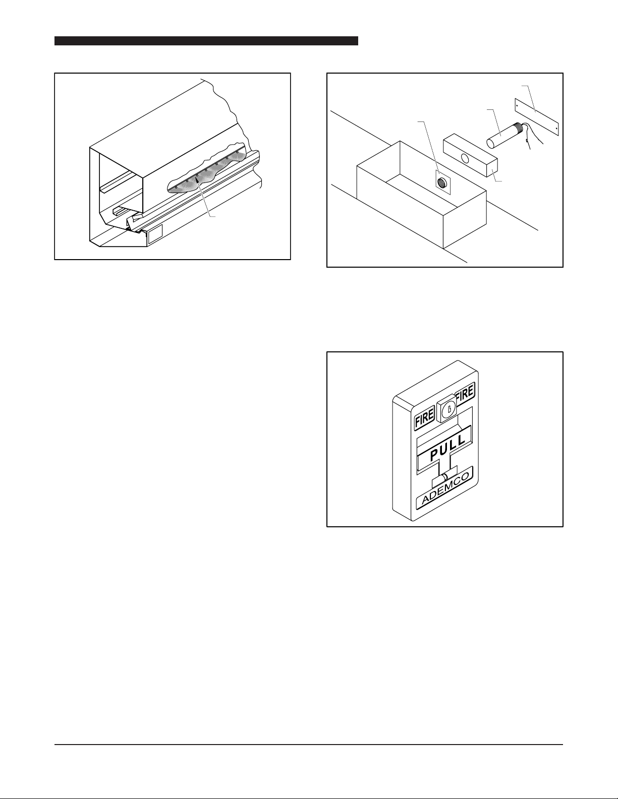
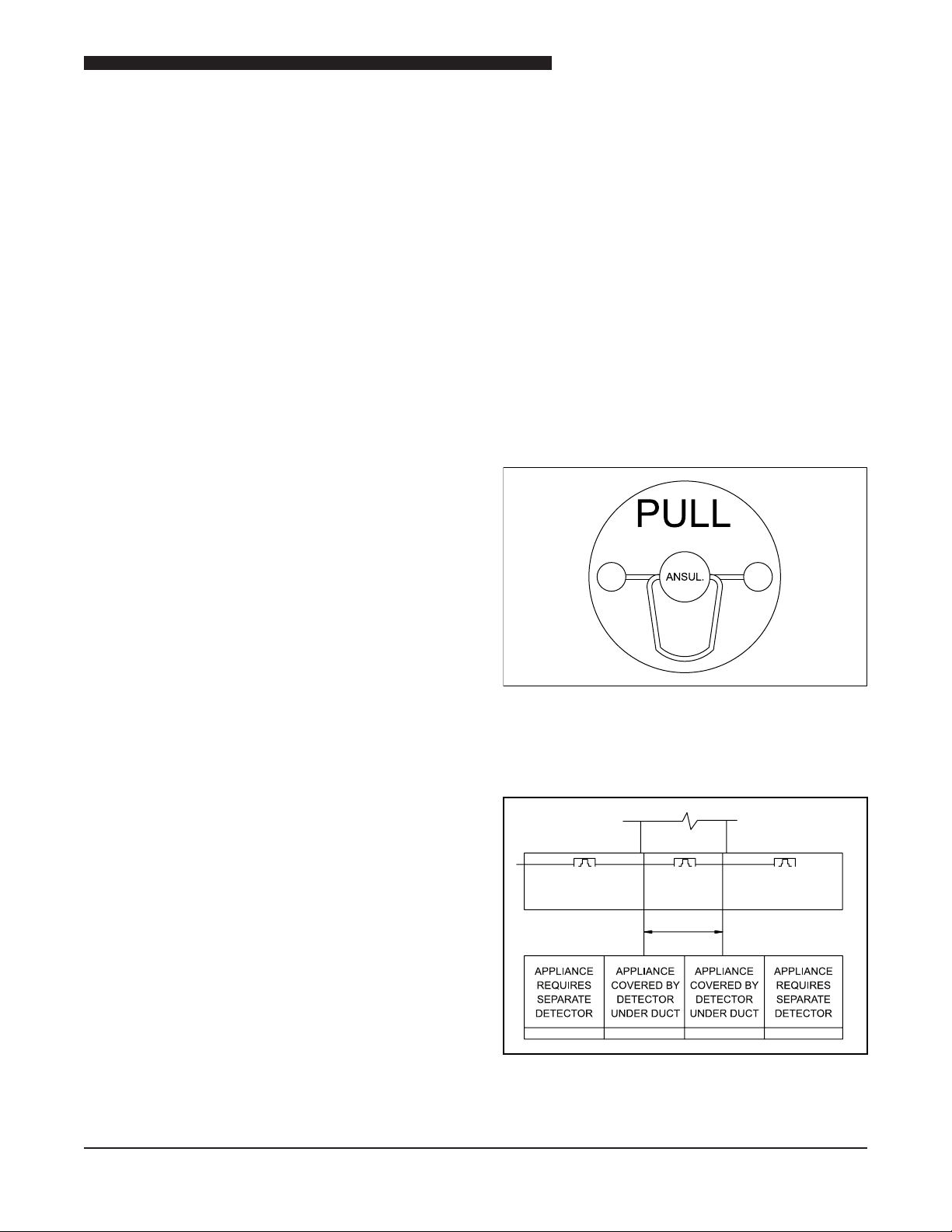
The re protection cycle is automatically initiated by
thermostats located in the exhaust air path at the duct
collars of the ventilator.
Location of Fire Detection Thermostats
As a back up, there is a remote re pull furnished near
a door. When pulled, this device will provide the same
results as the automatic re cycle.
Remote Fire Pull
In case of re, pull for the instant activation of the
Ventilator Fire Cycle.
11
Water Wash Ventilator Owner’s Manual
SEQUENCE OF OPERATION
STANDARD CONTROL PANEL
Contaminants accumulated during the normal cooking
cycles are washed from the system at the end of each
operating cycle. This can be achieved automatically
(through the used of the Mode Commander) or manually
by turning OFF the exhausts fans using the Standard
Control Panel.
CAUTION: Always turn cooking equipment
off 15 minutes prior to shutting down the
exhaust system.
This will prevent accidental tripping of the appliance
re suppression system due to heat build-up when the
exhaust system is terminated.
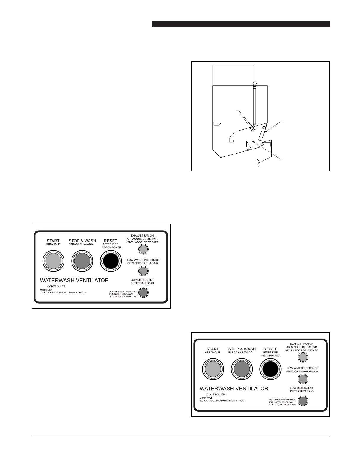
Spray
Nozzles
Damper Door
Extraction
Chamber
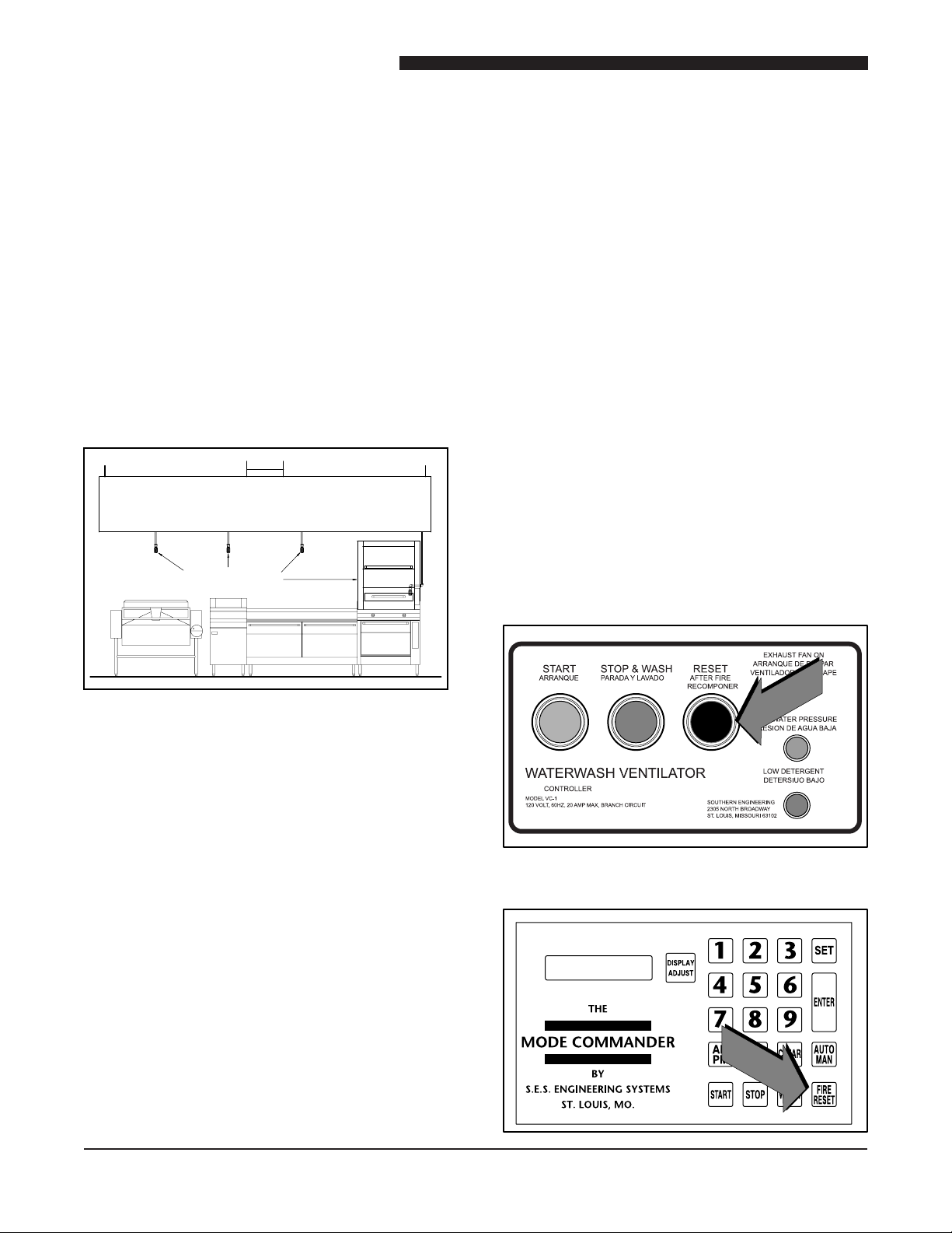
WASH CYCLE PROCEDURE
1. Turn off all cooking appliances and allow to cool
for minimum of 15 minutes.
2. Press the STOP & WASH button.
Water Wash Ventilator Controller
• The exhaust fan will coast to a stop
• The supply fan (if required) will stop.
Inlet Damper Location
• The wash solenoid valve will open and the detergent
pump will start.
• Hot detergent water (120°F @40 psi) will be injected
through the spray nozzles for a predetermined
period of time.
• When the wash cycle ends, the wash solenoid
closes terminating water ow, and the detergent
pump stops. The inlet damper will remain closed
awaiting the next fan cycle.
• When the Mode Commander is furnished, up to
four wash sequences may be run consecutively.
FAN CYCLE
Push the START button on the Control Panel.
• The inlet damper will close.
12
Water Wash Ventilator Controller
Water Wash Ventilator Owner’s Manual
• The Inlet damper will open.
• The Exhaust fan will start.
• Ventilator make-up air supply will start (if required).
• Turn on cooking appliances as needed.
CAUTION: Do not turn on cooking appliances if
inlet damper is closed or exhaust fan is not running.
Failure to comply my result in an accidental re
suppression discharge.
MODE COMMANDER
MANUAL MODE:
VENT #1 ON Damper opens, fan starts
VENT #1 STOP Fan stops, damper closes,
timed wash begins. Wash ends
after elapsed time, fan remains
OFF.
VENT #1 WASH Same sequence as stop
sequence
All Water Wash systems have two separate means of
re suppression built in to protect the ventilator and
duct system should a re occur.
APPLIANCE PROTECTION
This is the rst line of defense in the event of a re.
Basically, there are three types which will be discussed
in detail in separate sections of this manual. They are
water mist, dry chemical and wet chemical. Each type
is designed for one purposes, suppression of out of
control cooking res.
DRY AND WET CHEMICAL SYSTEMS
The dry chemical and wet chemical systems make
use of remote re pulls, usually located near an exit,
which when pulled will activate the chemical solution.
VENT #1 FIRE Upon manual or thermal
activation, fan stops, damper
closes, continuous suppressive
spray initiates. Remains in this
state until manual deactivated
by depressing the FIRE
RESET button.
NOTE: In order to deactivate re suppression,
the temperature in the extraction chamber must
be below 325°F.
NOTE: When multiple ventilators are supplied
with single fan systems, all sequences are
simultaneous with the exception of re status,
which remains individual.
VENT #1: Fan sequence is automatically initiated at
programmed times.
NOTE: May be repeated up to three cycles in a
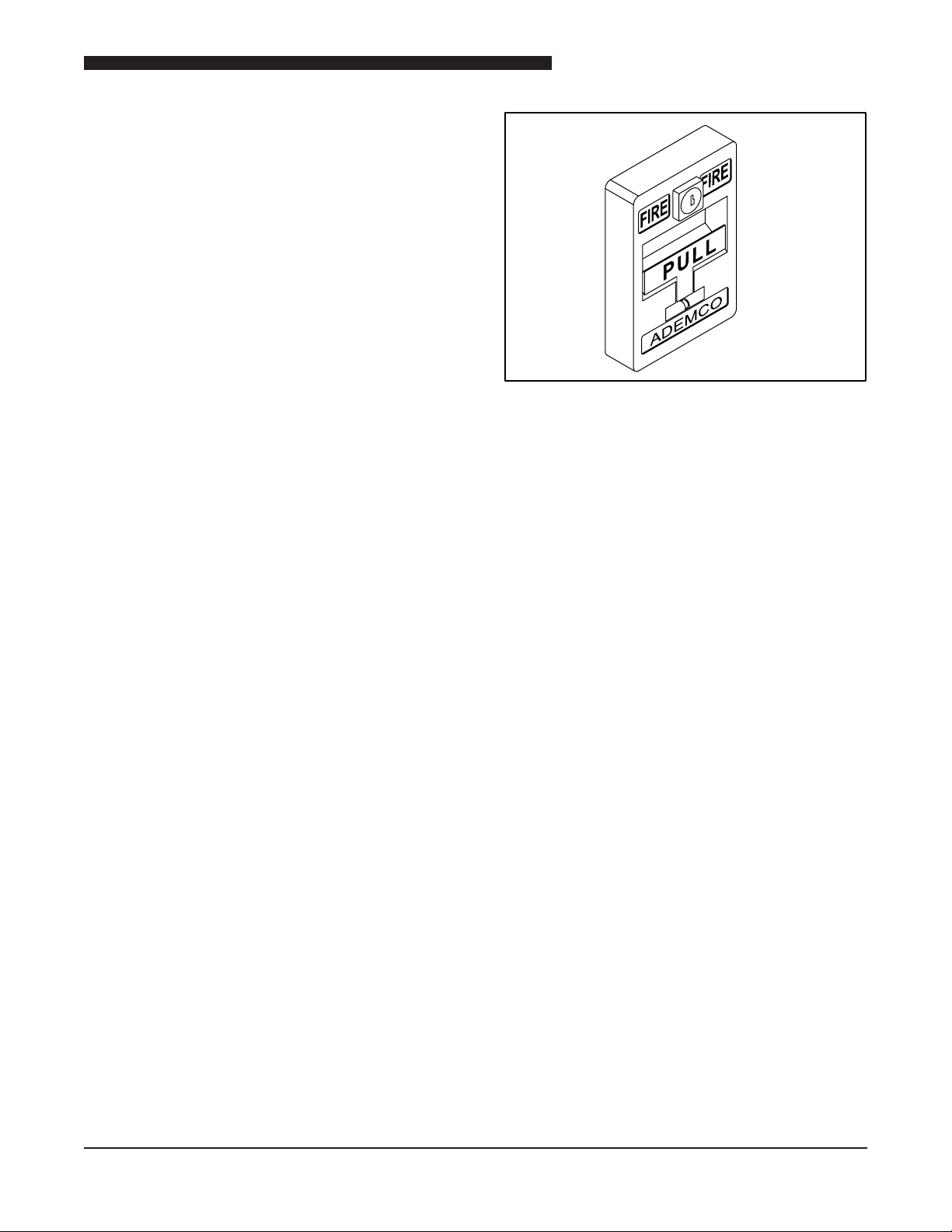
24-hour timeframe.
FIRE SUPPRESSION SYSTEMS
Typical Remote Fire Pull
They also employ fusible links which are located directly
above the cooking equipment.
Fusible Links above Appliances
When one of these links melt, the re suppression
system activates. When activated, wet or dry powder
13
Water Wash Ventilator Owner’s Manual
will be sprayed directly on the re through strategically
placed nozzles located above the appliances. Once
the chemicals are discharged, the gas valve will be
electrically or mechanically closed and the exhaust and
supply fans can be shut down or remain in operations
dependent upon local jurisdictional authority. Once
these systems are activated, the chemicals must be
replaced along with all fusible links which have been
affected. Once this is accomplished the gas valve can
be reset and normal operation resumed.
WATER FOG SYSTEM
When water fog systems are specied, there are some
basic differences which that should be noted. The
sprinkler nozzles are point of use and do not utilize
remote pulls or fusible links.
WATER FOG
NOZZLES
All Water Wash Ventilators utilize built in methods
of re suppression acting separately of appliance
protection. In the event a re has not been suppressed
and is drawn into the extraction chamber causing
a temperature rise above 325°F (275°F on down
draft models), re-stat contacts will close, sending a
signal to the ventilator control panel. The following
sequences will occur.
1. The exhaust fan shuts off, stopping the induced
draft over the cooking equipment and preventing
re from being pulled into the ductwork.
2. The UL rated damper door at the inlet to the
extraction chamber closes and provides a barrier
to the re, preventing a heat induced draft from
rising up the exhaust shaft.
3. The water-detergent wash system is activated,
releasing its water spray within the ventilator to
quench any re, wash away grease and dust that
could support combustion, and cool the damper
and extraction chamber, protecting the ventilator
from heat damage.
4. The water spay continues until the thermostat(s)
cool below 325°F and the FIRE RESET button on
the ventilator control panel is reset,
Typical Water Fog System
When a nozzle vial is heated to the designated
temperature and breaks, a continuous water spray
begins. Unlike chemical systems, all nozzles do not
open unless each/all are heated. Water continues
to ow until it is manually stopped. As with chemical
systems, the gas or electric appliances will be shut
down along with the exhaust system as required. All
systems may be incorporated with automatic signaling
devices for alarms.
WATER WASH FIRE SUPPRESSION
Fire Reset Button on Standard Control
14
Fire Reset Button on Mode Commander
5. A remote manual re pull switch is provided for
mounting in the exit path of the kitchen area. This
switch activates the re protection cycle. The re
switch (ber disc or glass bar) must be replaced
and the FIRE RESET button pushed before the
ventilation system can be restarted. If a remote
manual re switch or other device (such as a re
suppression system) activates the re protection
cycle, this device must also be reset to normal or
supervisory status before the FIRE RESET button
on the control panel will have any effect.
Water Wash Ventilator Owner’s Manual
6. The START button on the Control Panel may then
be pushed to restart the ventilation system.
15
Water Wash Ventilator Owner’s Manual
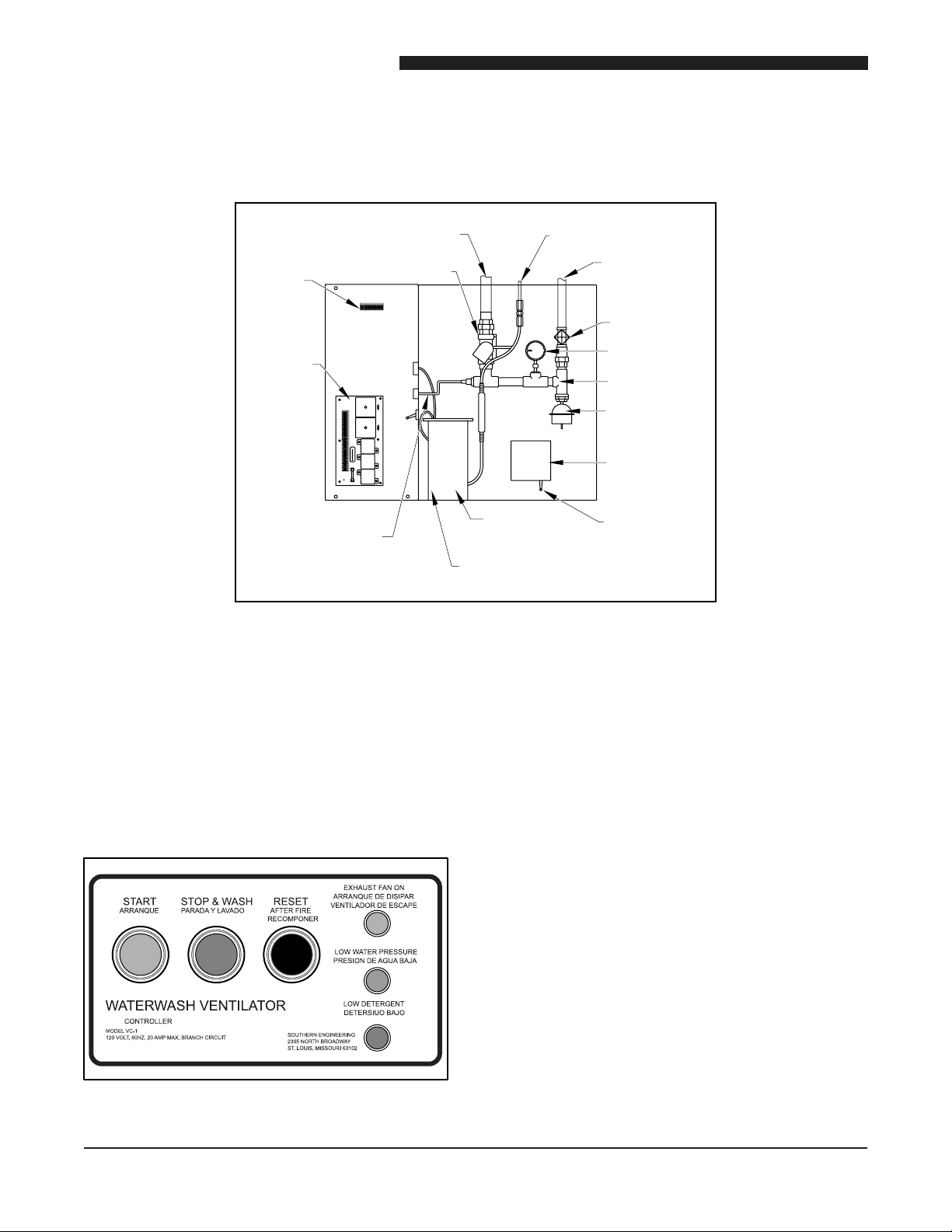
COMPONENT IDENTIFICATION AND ACCESS
STANDARD CONTROL CABINET
Hot Water Outlet
Terminal
Solenoid Valve
Strip
N H H17 N1 9
Circuit
Board
(See
separate
drawing)
SOUTHERN
WATER WASH
VC1
12
11
10
9
38
8
7
6
5
4
30
20
1
H1
H
G
REPLACE FUSE WITH
THE SAME TYPE AND
RATING ONLY
WST
WSR
WT
WR
TR
02F-SWW-00115A
84-0124 SECO WATER WASH
FR
DIR
MPA-3
Miniature
Pilot
Actuator
This enclosure serves as the xture for the major
electrical and plumbing components utilized by the
ventilator system. Basically the cabinet is divided into
two sections: The electrical compartment on the left side
and the plumbing components on the right. For ease
in identication the components will be discussed in
separate sections: Electrical Compartment, Plumbing
Compartment, Externally Mounted Components, and
Ventilator Mounted Components.
PUSH BUTTON CONTROL
1/4" Detergent Outlet
Hot Water
Supply
Shutoff Valve
Pressure/Temp.
Gauge
Line Strainer
Shock
Arrestor
Detergent
Pump
Detergent
Container
Pump Test
Switch
Detergent Tube Assembly
w/Foot Valve Strainer
START: The green start button is a normally open
switch. Momentary contact close the electrical circuit
to the damper interlock relay energizing the exhaust
fan and blower pilot light.
NOTE: The system must have water pressure
to complete the start sequence.
STOP: The red stop button is a SPDT switch providing
maintained contact with the start button when not
depressed. When depressed, the stop button will stop
the exhaust fans, close the inlet damper and initiate
the wash cycle.
All system functions are controlled by the Push Button
Control.
16
RESET: The black re reset button is normally closed.
When pressed, the re cycle relay is opened terminating
a re cycle.
NOTE: When a re cycle is initiated the STOP
and WASH function will be bypassed
NOTE: All Southern Engineering by Duke re
devices such as the remote re pull and thermostats
must be in normal operating condition before the
termination of a re cycle may be achieved.
EXHAUST FAN PILOT (EFP): Illuminates green when
the exhaust fan is operating, indicating power to the
damper interlock relay.
 Loading...