

Duke FBB-XY-230-AAB Service Manual
FLEXIBLE BATCH
BROILER
MODELS
FBB-XY-230-AAB
Service Manual
CE Version
Please read this manual completely before attempting
to install, operate or service this equipment
This document is prepared for trained Duke service technicians. It is not to be used by anyone not
properly qualied to perform these procedures.
This Service Manual is not all encompassing. If you have not been trained on servicing this product,
be sure to read the manual completely before attempting servicing. Be sure all necessary tools, test
equipment, and skills are available. Those procedures for which you do not have the proper skills
and test equipment must be performed only by a qualied Duke trained service technician.
This manual is Copyright © 2010 Duke Manufacturing Co. All rights reserved.
Reproduction without written permission is prohibited. Duke is a registered
trademark of the Duke Manufacturing Co.
Duke Manufacturing Co.
2305 N. Broadway
St. Louis, MO 63102
Phone: 314-231-1130
Toll Free: 1-800-735-3853
Fax: 314-231-2460
www.dukemfg.com
P/N 175922B

Service Manual for Flexible Batch Broiler Units
IMPORTANT WARNING AND SAFETY INFORMATION
IMPORTANT FOR YOUR SAFETY
THIS MANUAL HAS BEEN PREPARED FOR PERSONNEL QUALIFIED TO INSTALL
GAS EQUIPMENT. THE QUALIFIED INSTALLER SHOULD PERFORM THE INITIAL
FIELD START-UP AND ADJUSTMENTS OF THE EQUIPMENT COVERED BY THIS
MANUAL.
IMPORTANT
THE INSTRUCTIONS TO BE FOLLOWED IN THE EVENT THE SMELL OF GAS IS
DETECTED SHOULD BE POSTED IN A PROMINENT LOCATION. THIS INFORMATION
CAN BE OBTAINED FROM THE LOCAL GAS SUPPLIER.
IMPORTANT
IN THE EVENT A GAS ODOR IS DETECTED, SHUT DOWN BROILER AT MAIN
SHUTOFF VALVE AND CONTACT THE LOCAL GAS COMPANY OR GAS SUPPLIER
FOR SERVICE.
IMPORTANT FOR YOUR SAFETY
DO NOT STORE OR USE GASOLINE OR OTHER FLAMMABLE VAPORS OR
LIQUIDS IN THE VICINITY OF THIS OR ANY OTHER APPLIANCE.
WARNING
IMPROPER INSTALLATION, ADJUSTMENT, ALTERATION, SERVICE OR MAINTENANCE
CAN CAUSE PROPERTY DAMAGE, INJURY OR DEATH. READ THE INSTALLATION,
OPERATING AND MAINTENANCE INSTRUCTIONS THOROUGHLY BEFORE INSTALLING
OR SERVICING THIS EQUIPMENT.
WARNING
IN THE EVENT OF A POWER FAILURE, DO NOT ATTEMPT TO OPERATE THIS
DEVICE.
2

Service Manual for Flexible Batch Broiler Units
TABLE OF CONTENTS
INSTALLATION ...................................................................................................................5
OPERATION ........................................................................................................................5
CLEANING .......................................................................................................................... 5
SPECIFICATIONS ............................................................................................................... 6
TOOLS ..............................................................................................................................6
Standard .......................................................................................................................6
REMOVAL AND REPLACEMENT OF COMPONENTS ...................................................... 7
COVERS AND PANELS ...................................................................................................... 7
Upper Lift Off Panel ......................................................................................................7
Lower Control Side Service Panel ................................................................................7
Discharge Tray .............................................................................................................8
Discharge Hood ............................................................................................................8
Discharge Chute ...........................................................................................................8
Discharge Pan ..............................................................................................................9
Discharge Grease Pan .................................................................................................9
Discharge Access Panel ...............................................................................................10
Main Grease Pan .........................................................................................................10
Grease V Pan ...............................................................................................................10
Loader Tray ..................................................................................................................11
Conveyor Drive Motor Cover ........................................................................................11
Top Service Panel ........................................................................................................12
Removing the Front Panel ............................................................................................12
Removing the Rear Panel ............................................................................................12
COMPONENT REMOVAL ................................................................................................... 13
Conveyor Drive Motor Assembly ..................................................................................13
Conveyor Drive Chain .................................................................................................14
Conveyor Drive Motor Sprocket ...................................................................................14
Conveyor Drive Motor Capacitor ..................................................................................15
Blower Hose .................................................................................................................16
Upper Flame Sensor Assembly ....................................................................................16
Upper Igniter Assembly ................................................................................................17
Lower Flame Sensor Assembly ....................................................................................17
Lower Igniter Assembly ................................................................................................18
Upper Infrared Burner Assembly ..................................................................................18
Lower J Burner ............................................................................................................19
Ignition Modules ...........................................................................................................20
Combo Gas Valves .......................................................................................................20
Cook Chamber Temperature Probe..............................................................................21
Control Board ...............................................................................................................22
Step-Down Transformers .............................................................................................23
3

Service Manual for Flexible Batch Broiler Units
TABLE OF CONTENTS (CONTINUED)
Solid-State Relays ........................................................................................................23
Main Power Switch .......................................................................................................24
Blower Motor ................................................................................................................24
Replacing Conveyor Links ............................................................................................25
ADJUSTMENTS ..................................................................................................................26
Combo Gas Valves .......................................................................................................26
Drive Chain Deection ..................................................................................................27
Conveyor Position Adjustment .....................................................................................27
Upper Infrared Burner Air Supply .................................................................................28
Lower Burner Air Supply ...............................................................................................28
TROUBLESHOOTING CHART ...........................................................................................29
SCHEMATIC DIAGRAM ...................................................................................................... 39
REPLACEMENT PARTS LIST ............................................................................................40
4

Service Manual for Flexible Batch Broiler Units
INTRODUCTION
INSTALLATION
For detailed installation instructions, refer to the
Installation and Operation Manual.
OPERATION
For specic operating instructions, refer to the
Installation and Operation Manual.
CLEANING
For specic cleaning instructions, refer to the
Installation and Operation Manual.
5

Service Manual for Flexible Batch Broiler Units
CE SPECIFICATIONS
G20 G25 G30 G31
ALTITUDE (MAXIMUM) 607 m 607 m 607 m 607 m
GROSS HEAT INPUT 26.4 KW 26.4 KW 26.4 KW 26.4KW
GAS PIP CONNECTION 12.7 mm BSPT 12.7 mm BSPT 12.7 mm BSPT 12.7 mm BSPT
Supply Pressure 20 mbar 25 mbar 28-30 mbar 37-50 mbar
IR burner Pressure 9.34 mbar 12.95 mbar 19.93 mbar 19.93 mbar
Lower Burner Pressure 9.34 mbar 12.95 mbar 19.93 mbar 19.93 mbar
ORIFICE – Front IR burner 2.35 2.35 1.40 1.55
ORIFICE – Rear IR Burner 2.50 2.50 1.51 1.61
ORIFICE – Lower Burner 3.02 3.02 1.61 1.61
SHIPPING WEIGHT 205 KG (450 lbs)
SHIPPING DIMENSIONS 121.9 cm x 99.1 cm x 172.7 cm (483 x 393 x683 )
ELECTRICAL RATING 230 Volts 50 Hz 250 W
Model Number Information:
FBB-XY-230-AAB
X = 1 Reference Gas G31
X = 2 Reference Gas G20
X = 3 Reference Gas G30
X = 5 Reference Gas G25
Y = O No Catalyst
Y = C With Catalyst
AA = ISO 2 Digit Country Code
B = Future use
TOOLS
Standard
• Standard set of hand tools.
• VOM with AC current tester (Any quality VOM
with a sensitivity of at least 20,000 ohms per
volt can be used).
• Manometer
• Pyrometer
• Gas Leakage Tester or method to test for gas
leaks
• Conveyor Link Removal Pliers
• Duke Testing Harness
6
Service Manual for Flexible Batch Broiler Units
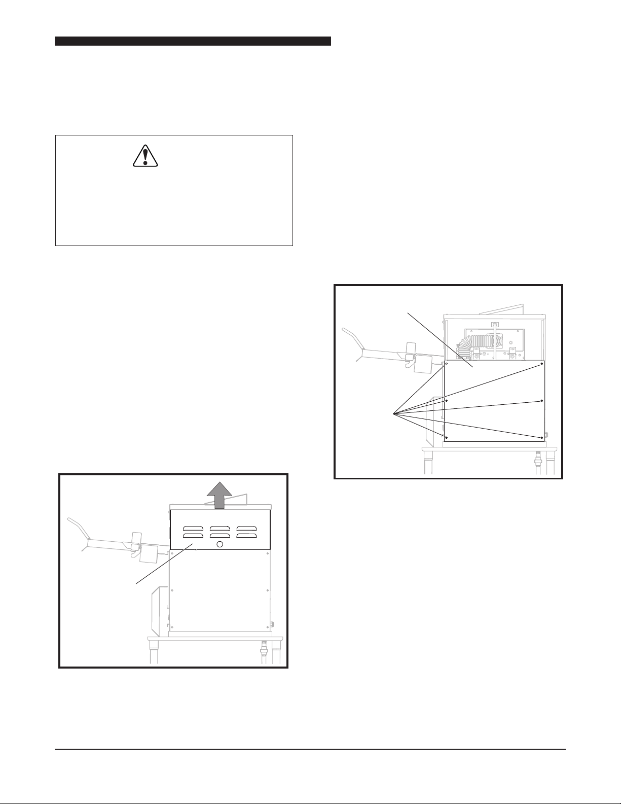
Control Side
Access Panel
Control Side
Service Panel
Screws
REMOVAL AND REPLACEMENT OF COMPONENTS
COVERS AND PANELS
WARNING
DISCONNECT THE ELECTRICAL
POWER TO THE BROILER AND
FOLLOW LOCKOUT / TAGOUT
PROCEDURES.
Caution: If the broiler has been operating,
broiler panels and components
may be hot. Use PROPER
PROTECTION.
Upper Lift Off Panel
The Upper Lift Off Panel provides access to
the Upper Flame Sensors, Igniters and Blower
Hose.
1. Remove Upper Lift Off Panel by lifting up
and removing from broiler.
2. Install Upper Lift Off Panel by lowering
into the side grooves.
Upper Lift Off Panel
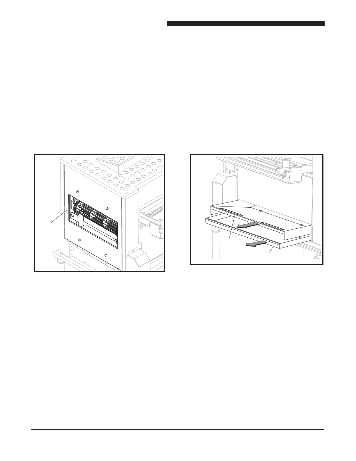
Lower Control Side Service Panel
The Lower Control Side Service Panel
provides access to the Combo Gas Valves,
Ignition Modules, Transformers, Blower Motor,
Conveyor Motor Capacitor, and electrical
connections to the Control Board.
1. Remove the six screws securing the
Lower Control Side Service Panel.
2. Remove the panel from the broiler.
3. Reverse procedure to install the Lower
Control Side Service Panel.
7
Service Manual for Flexible Batch Broiler Units
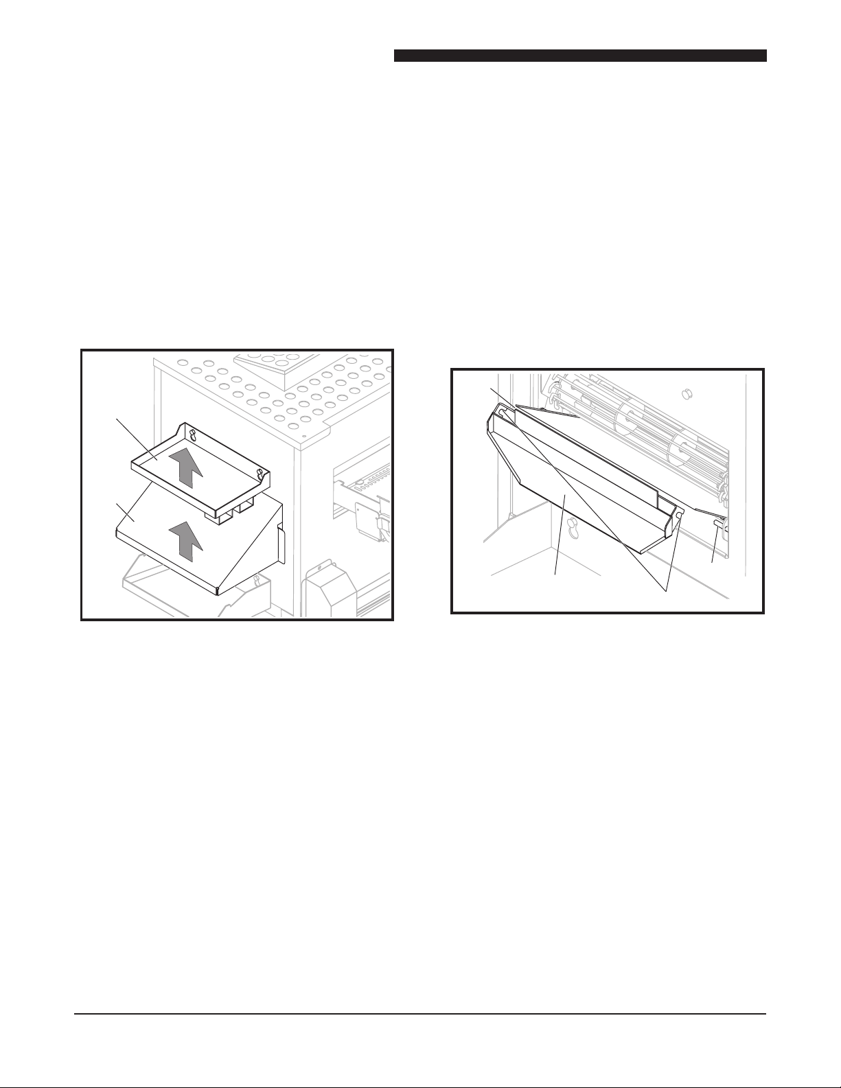
PHU
Pan
Shelf
Discharge
Hood
Discharge
Chute Hook
Pin
Pin
Lower Control Side Service Panel
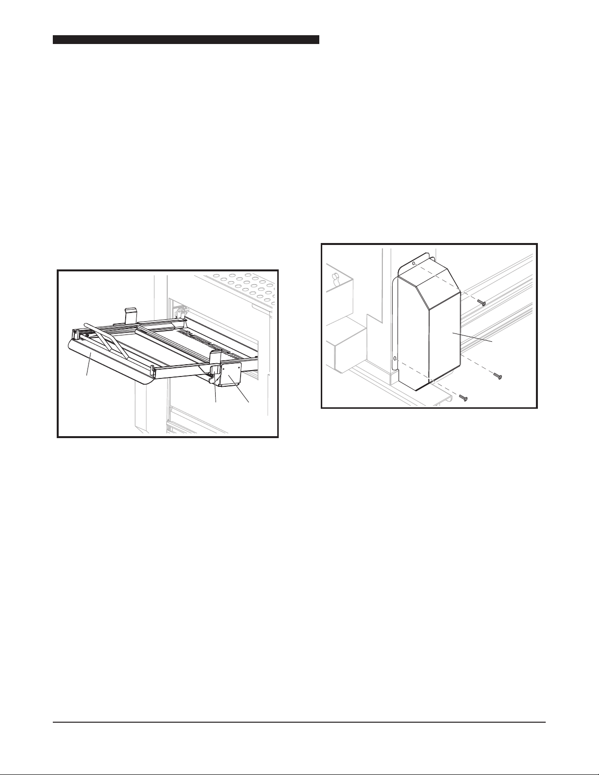
PHU Pan Shelf
The PHU Pan Shelf is located on the discharge
side of the broiler and holds the unused holding
pans.
1. Lift the pan shelf up and remove.
2. To install the pan shelf, slide the keyholes
over the two screws and slide pan shelf
down.
Discharge Chute
The Discharge Chute is located under the
Discharge Hood and guides the patties from the
conveyor into the Discharge Pan.
1. Remove PHU Pan Shelf.
2. Remove the Discharge Hood.
3. Remove Discharge Chute by lifting off of the
two side pins.
4. Reverse procedure to install Discharge Chute,
being sure to rest the hooks onto the pins on
both sides.
PHU Pan Shelf and Discharge Hood
Discharge Hood
The Discharge Hood is located on the discharge
side of the broiler under the PHU Pan Shelf.
1. Remove the PHU Pan Shelf.
2. Remove the Discharge Hood by lifting out.
3. Install Discharge Hood by lowering into the
side grooves.
4. Reinstall the PHU Pan Shelf.
8
Discharge Chute
Service Manual for Flexible Batch Broiler Units
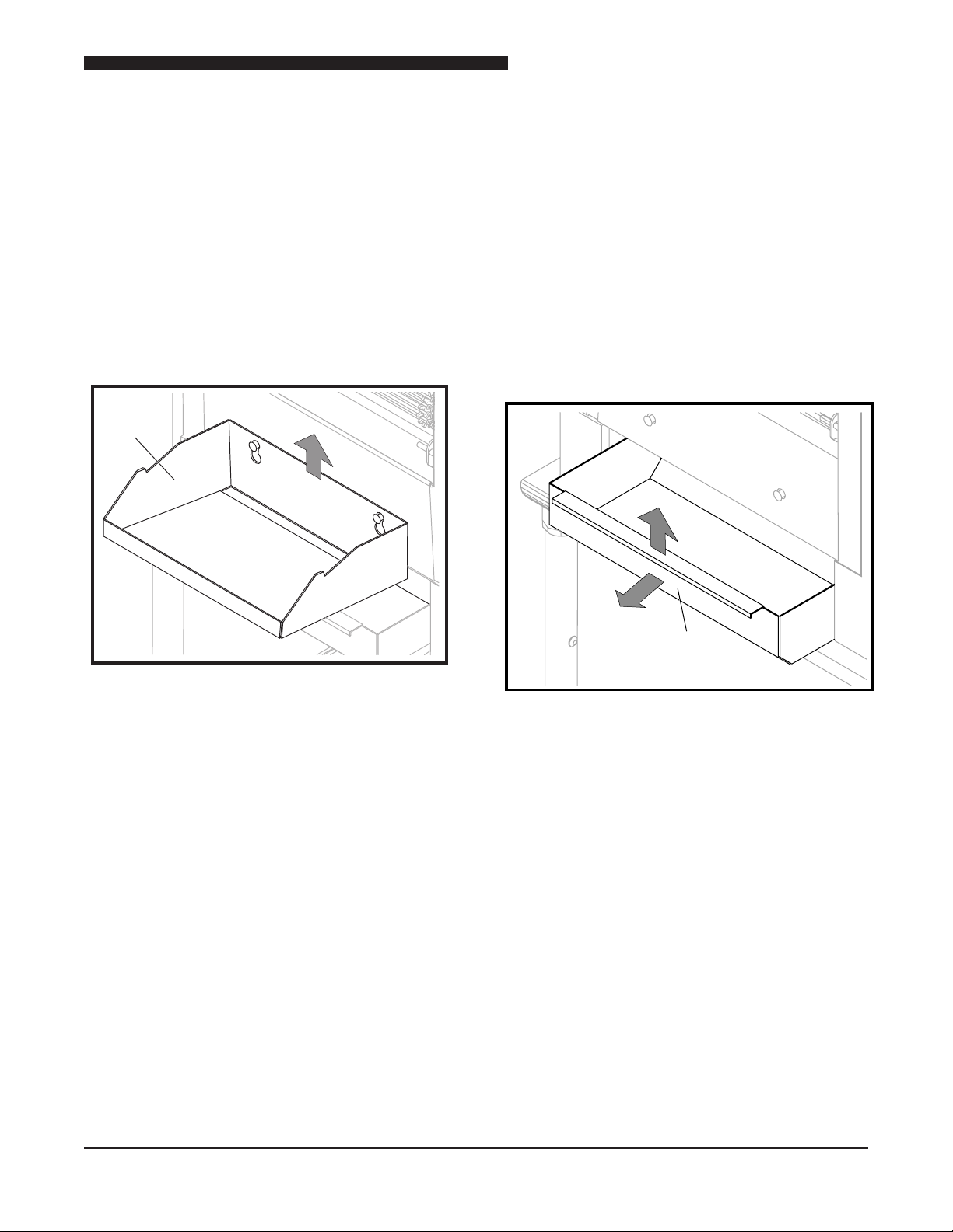
Discharge
Pan
Discharge
Grease
Pan
1
2
Discharge Pan
The Discharge Pan is located on the discharge
side of the broiler below the Discharge Hood
and is used to support the PHU Holding Pan (not
supplied).
1. Remove the PHU Holding Pan if present.
2. Slide Discharge Pan up and out of keyhole
slots.
3. Install Discharge Pan by lowering it into the
thumbscrews.
Discharge Grease Pan
The Discharge Grease Pan is located below
the Discharge Pan and catches any grease
drippings.
1. Tilt Discharge Grease Pan up to unhook and
pull forward to remove.
2. When installing the Discharge Grease Pan,
be sure to tilt up and push all the way back.
NOTE: Correct positioning will not allow pan
removal without upward tilt.
Discharge Pan
Discharge Grease Pan
9
Service Manual for Flexible Batch Broiler Units
Discharge
Side
Access
Panel
Discharge
Side
Access
Panel
Main
Grease Pan
Grease
V-Pan
Discharge Access Panel
1. Remove the PHU Pan Shelf.
2. Remove Discharge Hood.
3. Remove Discharge Chute.
4. Remove Discharge Pan.
5. Remove Discharge Grease Pan.
6. Remove Discharge Access Panel by lifting it
up and out.
7. Reverse procedure to install Discharge Access
Panel.
Main Grease Pan
The Main Grease Pan is located on the front of
the broiler under the V Grease Pan.
Remove the Main Grease Pan by sliding straight
out of broiler.
V Grease Pan
The V Grease Pan is located on the front of the
broiler under the Loader Tray.
Remove pan by sliding straight out from broiler.
10
Discharge Access Panel
V Grease Pan and Main Grease Pan
Service Manual for Flexible Batch Broiler Units
Loader
Carriage
Loader
Bracket
Ear
Conveyor
Drive
Motor
Cover
Loader Tray
The Loader Tray is located on the front of the
broiler and slides into the channels on the Loader
Brackets.
1. Remove Loader by sliding it out of the Loader
Tray.
2. Remove Loader Tray from the Loader Brackets
by pulling forward and disengaging ears on
Loader Tray from keepers on the Loader
Brackets.
3. Install Loader Tray by sliding it into bracket
and engaging ears with keepers.
Conveyor Drive Motor Cover
The Conveyor Drive Motor Cover, located on the
lower front of the broiler on the discharge side,
covers the Drive Chain Motor.
1. Remove the Main Grease Pan and the V
Grease Pan.
2. Remove the three screws securing the cover
to the broiler.
3. Lift Conveyor Drive Motor Cover off the broiler.
Loader Tray
Conveyor Drive Motor Cover
11
Service Manual for Flexible Batch Broiler Units
Top
Service
Panel
Flue
Restrictor
Front Access Panel
Rear Access Panel
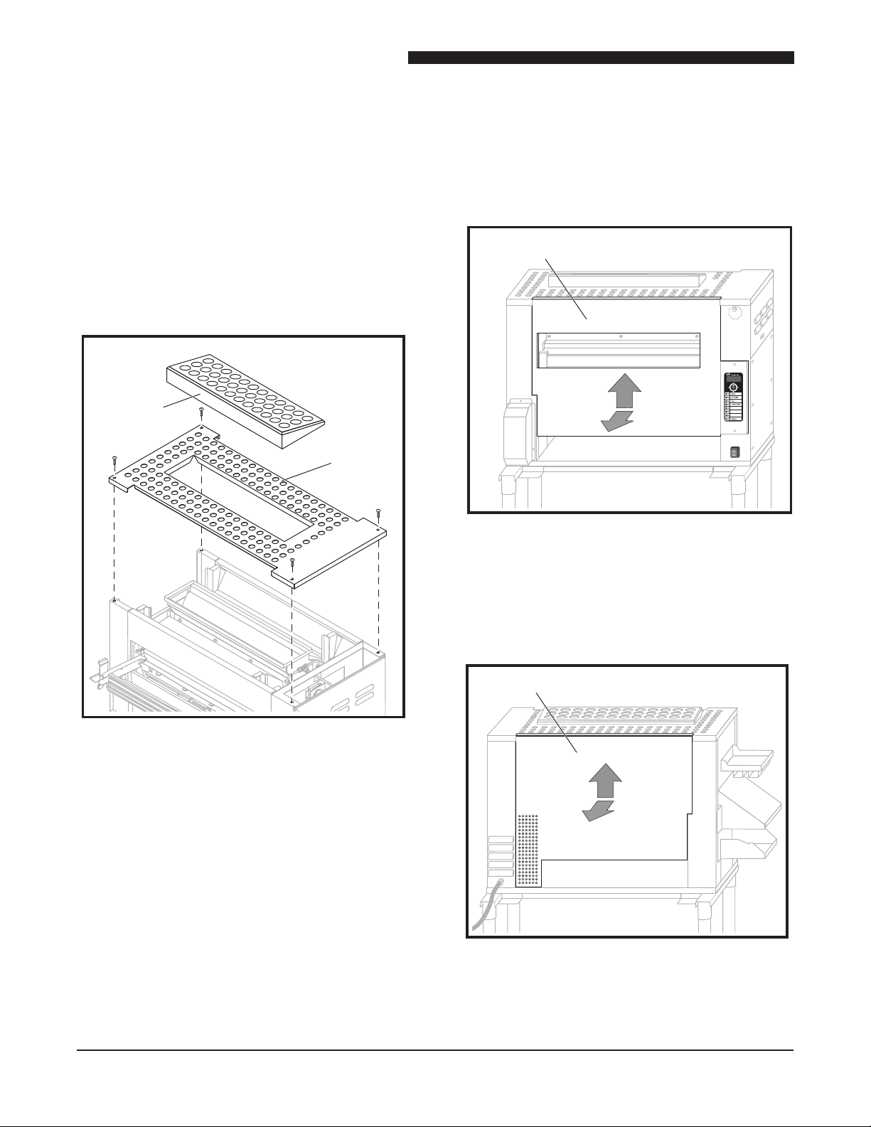
Top Service Panel
The perforated Top Service Panel provides access
to the two Infrared Burners
1. Remove the four screws securing the
perforated Top Service Panel.
2. Remove the perforated Top Service Panel
from the broiler.
3. Reverse procedure to install the perforated
Top Service Panel.
5. Lift the Front Panel up and away from the
broiler.
6. Reverse these steps to reinstall these parts.
Front Panel
Removing the Front Panel
1. Slide the Loader out of the Loader Tray.
2. Unlatch the Loader Tray and slide it out of the
Loader Tray Mounting Brackets.
3. Pull the Main Grease Pan out of the front of
the broiler.
4. Pull the V Grease Pan out of the front of the
broiler.
Removing the Rear Panel
1. Lift the Rear Panel up and away from the
broiler.
2. Reverse to reinstall the Rear Panel.
Top Service Panel
Rear Panel
12

COMPONENT REMOVAL
Motor
Assembly
Screws
Motor
Mounting
Plate
Chain
Motor
Sprocket
CONVEYOR DRIVE MOTOR ASSEMBLY
The Conveyor Drive Motor Assembly is located
in the lower front of the broiler at the discharge
end. The motor drives the Conveyor by use of a
drive chain.
WARNING
DISCONNECT THE ELECTRICAL
POWER TO THE BROILER AND
FOLLOW LOCKOUT / TAGOUT
PROCEDURES.
1. Remove the Conveyor Drive Motor Cover.
Refer to the COVERS and PANELS section
of the manual.
Service Manual for Flexible Batch Broiler Units
Conveyor Drive Motor Assembly
2. Disconnect wires to motor.
3. Remove Discharge Access Panel. Refer to
the COVERS and PANELS section of the
manual.
4. Remove four screws securing motor to
mounting plate and remove motor.
5. Raise motor mounting plate to disengage drive
chain from motor pulley.
6. Remove sprocket from motor shaft. Sprocket
is secured to motor shaft by two set screws.
7. Reverse procedure to install a new motor.
Ensure that one of the sprocket set screws is
tightened to the at side of the motor shaft.
NOTE: When installing the new motor, be sure to
engage the chain on the motor sprocket. Adjust
the tension on the chain to allow 4.763 mm chain
deection, as described in the procedure DRIVE
CHAIN DEFLECTION ADJUSTMENT in the
ADJUSTMENT Section, before tightening the
motor mounting plate screws.
Motor Sprocket and Drive Chain
13
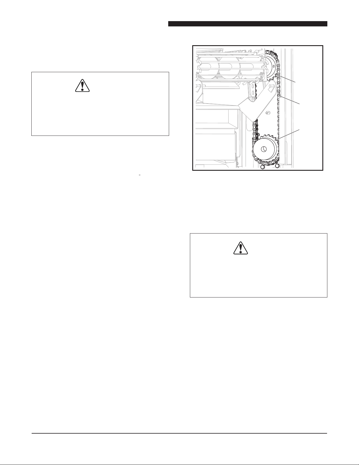
Service Manual for Flexible Batch Broiler Units
Conveyor
Sprocket
Motor
Sprocket
Chain
Conveyor Drive Chain
The Conveyor Drive Chain connects the drive
motor to the Conveyor.
WARNING
DISCONNECT THE ELECTRICAL
POWER TO THE BROILER AND
FOLLOW LOCKOUT / TAGOUT
PROCEDURES.
1. Remove Conveyor Drive Motor Cover. Refer
to the COVERS and PANELS section of the
manual.
2. Remove Discharge Access Panel. Refer to
the COVERS and PANELS section of the
manual.
Drive Chain and Sprockets
3. Disconnect motor wires.
4. Remove four screws securing motor mounting
plate.
5. Raise motor mounting plate to disengage drive
chain from motor sprocket.
6. Disengage chain from conveyor sprocket.
7. Remove chain from broiler by removing the
master link.
8. Reverse procedure to install a new chain.
NOTE: When installing the new chain, be sure
to engage the chain on the motor sprocket
and conveyor sprocket. Then adjust the
tension on the chain to allow 4.763 mm chain
deection, as described in the procedure DRIVE
CHAIN DEFLECTION ADJUSTMENT in the
ADJUSTMENT Section, before tightening the
motor mounting plate screws.
Conveyor Drive Motor Sprocket
The Conveyor Drive Motor Sprocket is attached
to the motor shaft.
WARNING
DISCONNECT THE ELECTRICAL
POWER TO THE BROILER AND
FOLLOW LOCKOUT / TAGOUT
PROCEDURES.
1. Remove Conveyor Drive Motor Cover. Refer
to the COVERS and PANELS section of the
manual.
2. Remove Discharge Access Panel. Refer to
the COVERS and PANELS section of the
manual.
3. Disconnect the motor wires.
14
4. Remove the four screws securing motor
mounting plate.
5. Raise motor mounting plate to disengage drive
chain from motor sprocket.
6. Disengage drive chain from motor sprocket.
 Loading...