

Duke FBBT-PC-120 Installation Manual
BURGER KING
FLEXIBLE
BATCH BROILER
WITH TOUCH
SCREEN CONTROL
Installation and
Operation Manual
Please read this manual completely before attempting
to install, operate or service this equipment
This manual is Copyright © 2017 Duke Manufacturing Co. All rights reserved.
Reproduction without written permission is prohibited. Duke is a registered
trademark of the Duke Manufacturing Co.
Duke Manufacturing Co.
2305 N. Broadway
St. Louis, MO 63102
Phone: 314-231-1130
Toll Free: 1-800-735-3853
Fax: 314-231-5074
www.dukemfg.com
P/N 176747B
03/06/2017

Installation and Operation of Flexible Batch Broiler
With Touch Screen Control
2

Installation and Operation of Flexible Batch Broiler
With Touch Screen Control
TABLE OF CONTENTS
IMPORTANT WARNING AND SAFETY INFORMATION ..................................................4
I. GENERAL INFORMATION ..........................................................................................5
A. BATCH BROILER SPECIFICATIONS ...............................................................5
II. INSTALLATION INSTRUCTIONS ..............................................................................7
A. VENTILATION .....................................................................................................7
B. INSTALLATION SPECIFICATIONS ................................................................... 8
C. DELIVERY AND INSPECTION .......................................................................... 8
D. BROILER ASSEMBLY ......................................................................................10
E. ADJUSTMENTS AT INSTALLATION ............................................................... 11
F. LOCATION OF THE BROILER ......................................................................... 12
G. GAS PIPING ....................................................................................................... 12
H. ELECTRICAL CONNECTIONS ........................................................................ 12
III. OPERATION INSTRUCTIONS ................................................................................14
A. DAILY BROILER START-UP .............................................................................15
B. COOKING PRODUCT........................................................................................16
C. SPECIAL FUNCTION SCREENS ..................................................................... 18
D. CLEANING .........................................................................................................23
IV. SERVICE AND REPAIR ...........................................................................................31
V. REPLACEMENT PARTS LIST ................................................................................. 33
VI. ELECTRICAL SCHEMATIC ....................................................................................35
3
Installation and Operation of Flexible Batch Broiler
WARNING
CAUTION
With Touch Screen Control
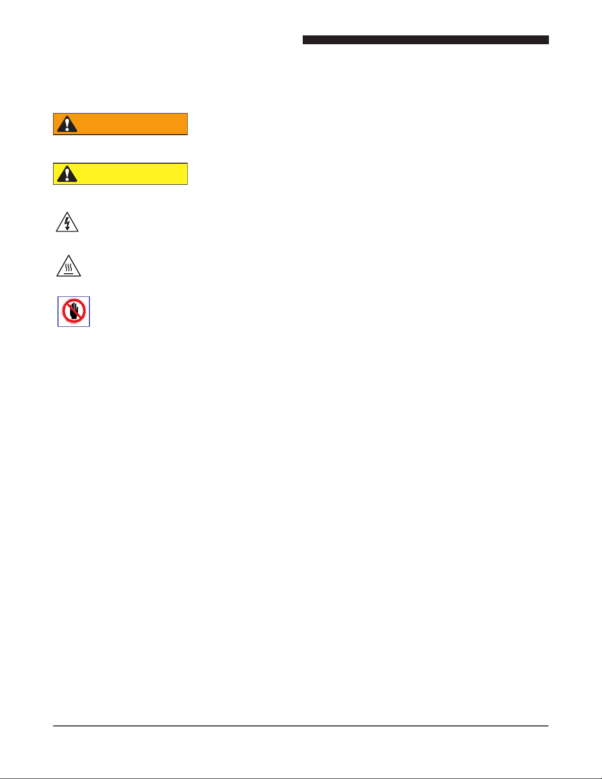
IMPORTANT WARNING AND SAFETY INFORMATION
HAZARD WHICH COULD RESULT IN DEATH OR SERIOUS
INJURY
HAZARD WHICH COULD RESULT IN MINOR OR MODERATE
INJURY
ELECTRICAL SHOCK HAZARD WHICH COULD RESULT IN DEATH OR SERIOUS
INJURY AND/OR EQUIPMENT DAMAGE
HOT SURFACE WHICH COULD RESULT IN MINOR OR MODERATE INJURY.
TASKS MUST BE PERFORMED ONLY FOLLOWING PROPER TRAINING
• Read all instructions before using equipment
• Do not attempt to defeat the grounded connector
• Install or locate the equipment, only for its intended use, as described in this manual.
• Do not use corrosive chemicals, water jet equipment, or other pressurized liquid spraying equipment to clean
this unit.
• Do not block any openings on the unit.
• Unit may start operating with inadvertent contact with the touch screen display or from other extraneous
sources. Turn off external mains supply disconnect and/or unplug the unit from the mains supply, should
abnormal or unwanted operations occur.
• This appliance is not intended for use by children or persons with reduced physical, sensory or mental
capabilities, or lack of experience and knowledge unless they have been given supervision or instruction
concerning use of the appliance by a person responsible for their safety. Children shall not play with the
appliance.
• Turnoff the external mains supply disconnect or disconnect the appliance line supply cord and allow the unit
to cool down before servicing or performing maintenance.
• The procedures in this manual may include the use of chemical products. You must read the Material Safety
Data Sheets (MSDS) before using any of these products.
• Properly rated all poles mains protection and earthing compliance with local codes are required for safe
operation of this unit.
• Disposal of this unit must be in accordance with local environmental codes and/or other applicable codes.
• Consult the local gas supplier for instructions to be followed in the event user smells gas.
• Do not store or use gasoline or other ammable vapors or liquids in the vicinity of this or any other appliance.
• SAVE THESE INSTRUCTIONS
4

Installation and Operation of Flexible Batch Broiler
With Touch Screen Control
I. GENERAL INFORMATION
A. Batch Broiler Specications
FLEXIBLE BATCH BROILER SPECIFICATIONS
NATURAL GAS PROPANE
ALTITUDE (MAXIMUM) 2000 FT 607 m 2000 FT 607 m
GAS PIPE CONNECTION 3/4" F-NPT 3/4" F-NPT
INLET PRESSURE RANGE 7" – 12" W.C. 10" – 12” W.C.
NOTE: High Pressure Kit is required if supply pressures are greater than 12.0” W.C. (3.0 kPa)
Reference Duke P.N. 175689
MANIFOLD PRESSURE MANIFOLD PRESSURE
INFRARED BURNERS (TOP) 3.75" W.C. 0.93 kPa 8.0" W.C. 2.0kPa
LOWER BURNER 3.75" W.C. 0.93 kPa 8.0" W.C. 2.0kPa
TOTAL ENERGY RATE
FRONT INFRARED BURNER #40 2.49mm #52 1.61mm
BACK INFRARED BURNER #36 2.70mm #51 1.70mm
LOWER BURNER #31 3.05mm #49 1.85mm
SHIPPING WEIGHT: 482 lbs (219 Kg)
SHIPPING DIMENSIONS: 47” x 34” x 68” (119.4 x 86.4 x 172.7 cm)
87000 – 111,000
BTU/HR
BURNER ORIFICE SIZE BURNER ORIFICE SIZE
25.5 – 32.5 kW79,000 – 105,000
BTU/HR
23.2 – 30.7
kW
MODEL NUMBER ELECTRIC NATURAL & LP GAS
FBBT-NO-120 120VAC, 2A, 60Hz 87,000 – 111,000 BTU/HR
FBBT-NC-120 120VAC, 2A, 60Hz 87,000 – 111,000 BTU/HR
FBBT-PO-120 120VAC, 2A, 60Hz 79,000 – 105,000 BTU/HR
FBBT-PC-120 120VAC, 2A, 60Hz 79,000 – 105,000 BTU/HR
A-1.0 Model Number Key
FBBT-XY-120
X = N (NATURAL GAS) OR P (PROPANE / LP GAS)
Y = O (NO CATALYST) OR C (CATALYST)
120 = 120 VOLTS
5
Installation and Operation of Flexible Batch Broiler
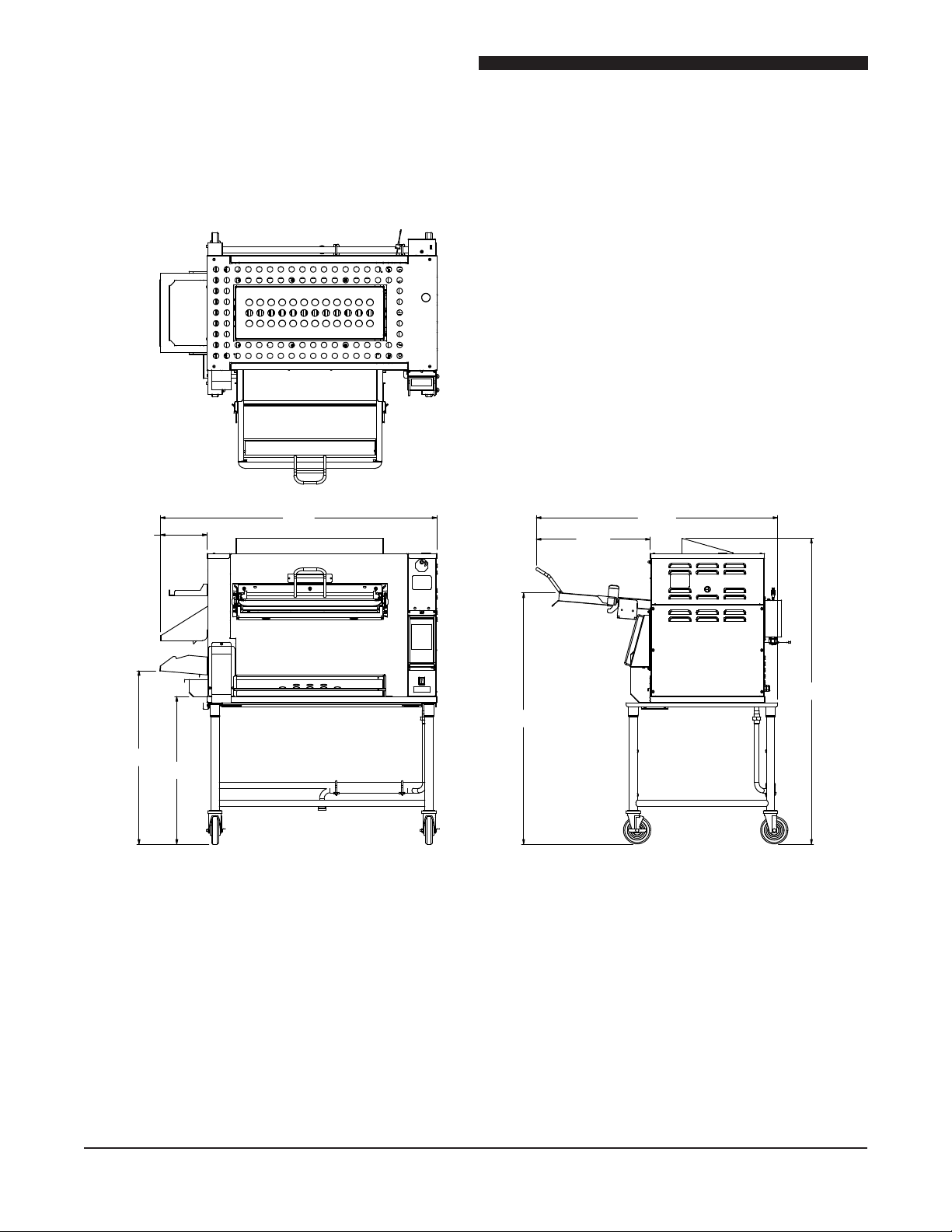
(100.3 cm)
With Touch Screen Control
A-2.0 Broiler Dimensions
8 1/2"
(21.6 cm)
39 1/2"
34 3/4"
(88.4 cm)
50 3/8"
(128 cm)
53 5/8"
(136.1 cm)
20 3/4"
(52.9 cm)
44"
(111.9 cm)
63 5/8"
(161.7 cm)
6

Installation and Operation of Flexible Batch Broiler
WARNING
With Touch Screen Control
II. INSTALLATION INSTRUCTIONS
The installation must conform with local codes, or in the absence of local codes, with the National Fuel Gas Code,
that complies with ANSI Z21.69 / CSA 6.16
Connectors for Moveable Gas Appliances
and a quick-disconnect device that complies
IMPROPER INSTALLATION,
ADJUSTMENT, ALTERATION,
SERVICE, OR MAINTENANCE CAN
CAUSE PROPERTY DAMAGE,
INJURY, OR DEATH. READ THE
INSTALLATION, OPERATING, AND
MAINTENANCE INSTRUCTIONS
BEFORE INSTALLING OR
SERVICING THIS EQUIPMENT.
Installation and/or service repair of gas
appliances requires Skilled or Qualied
Personnel. Skilled or Qualied Personnel are
individuals, rms, companies or corporations
which are directly authorized by Duke
Manufacturing (Assignee) or meet the
requirements of governmental authority having
jurisdiction for the task.
with ANSI Z21.4 / CSA 6.9 Quick –Disconnect
Devices for Use with Gas Fuel.
When installing a broiler mounted on casters
with quick-disconnect hose, adequate means
must be provided to limit the movement of the
broiler without depending on the connector,
hose, or system piping to limit movement. A
restraining device may be attached to the rear
vertical portion of the broiler’s base frame.
A. VENTILATION:
This appliance requires a ventilation system
to prevent unacceptable concentrations of
substances harmful to health in the room where
the appliance is installed.
Ventilation System Specications:
Electrical wiring tasks must be in conformance
with National Electrical Code ANSI/NFPA70
Gas supply interconnection must be in
conformance with National Fuel Gas Code
ANSI Z223.1/NFPA54 and Natural Gas and
Propane Installation Code CSAB149 including
the following:
• The appliance must have an individual manual
shutoff valve at the connection to the gas supply
piping system during any pressure testing of
that system at test pressures in excess of ½ psi
(3.5kPa).
• The appliance must be isolated from the gas
supply piping system by closing its individual
manual shut off valve during any pressure
testing of the gas supply systems at test
pressures equal to or less than ½ psi (3.5kPa).
For a broiler mounted on casters, the
installation must be made with a connector
Must be a Mechanically Driven Exhaust Hood
System
Minimum Capacity: 1,700 m3/hr (1,000 cfm)
Minimum Opening: 39.4” x 51.2” (100cm x
130cm)
The Ventilation System must be inspected,
maintained, and annually serviced by
Qualied Personnel as part of or in addition to
governmental requirements
NOTE: Ventilation Systems for multiple or
additional appliances must have capacity
in addition to the specications for this
appliance.
7
Installation and Operation of Flexible Batch Broiler
WARNING
With Touch Screen Control
Maintenance of Ventilation System
The ventilation system must be maintained and annually
inspected by Qualied Personnel concurrent as part of
or in addition to governmental requirements.
This inspection/maintenance should consist of, but
not be limited to:
• Inspection for blockages or build up which might
interfere with the venting of the broiler.
• Repair of such blockages.
• Inspection of the venting canopy, its drive
motors and bells, etc.
: Do not place any objects such as sheet
pans, food containers or aluminum foil on the top of
the broiler. This will obstruct the venting of cooking
vapors and airow through the unit—resulting in
poor cooking performance.
B. INSTALLATION SPECIFICATIONS:
The broiler has been fully tested before
shipping with adjustments to optimize operation
of the gas system IR (top) burners and bottom
burner. The Skilled or Qualied Personnel
installing the broiler must verify gas systems
adjustments to verify adjustments were not
impacted during transit shipping. Please
contact Duke Manufacturing Co. for adjustment
procedures.
This broiler must not be installed on a curb
base or sealed to a wall. The area around the
broiler must be clear of combustible materials.
Minimum clearances to combustible or
noncombustible surfaces are:
ELECTRICAL SPECIFICATIONS:
Electrical Rating: 120V~ 2A 60Hz
Line Connection: NEMA 15
ELECTRICAL SHOCK HAZARD
UNIT MUST BE SAFETY
GROUNDED, EARTHED.
DO NOT MODIFY OR DEFEAT
ELECTRICAL CONNECTIONS
C. DELIVERY AND INSPECTION
• The shipping carrier assumes liability and
responsibility for delivering the appliance
without damage. Duke Manufacturing Co. can
assist with resolution of any shipping related
issues if a problem arises.
• Look over the outer shipping container carefully
when delivered with the person making the
delivery.
• Note any exterior damage on the delivery
receipt before signing.
• The person making the delivery for the shipping
carrier must agree and sign the receipt to
document damage to the outer shipping
container.
• Unpack the broiler and inspect for any damage
not evident on the outer shipping container and
other concealed damage. The shipping carrier
must be notied any damages within fteen (15)
days of receipt.
Discharge end: 12.0” (305mm)
Rear of unit: 4.0” (102mm)
Side Access Panel (Control): 3.0” (76mm)
Floor / Table: 0” (0mm)
8
Installation and Operation of Flexible Batch Broiler
CAUTION
With Touch Screen Control
9. A minimum of three (3) people are required
4
2
to support and balance the broiler while
removing from the palate.
a. Roll the broiler forward until the front
5
caster are clear of the palate
b. Lift the broiler rear caster above the palate
3
and slide out the palate from under the
broiler.
4
5
7
8
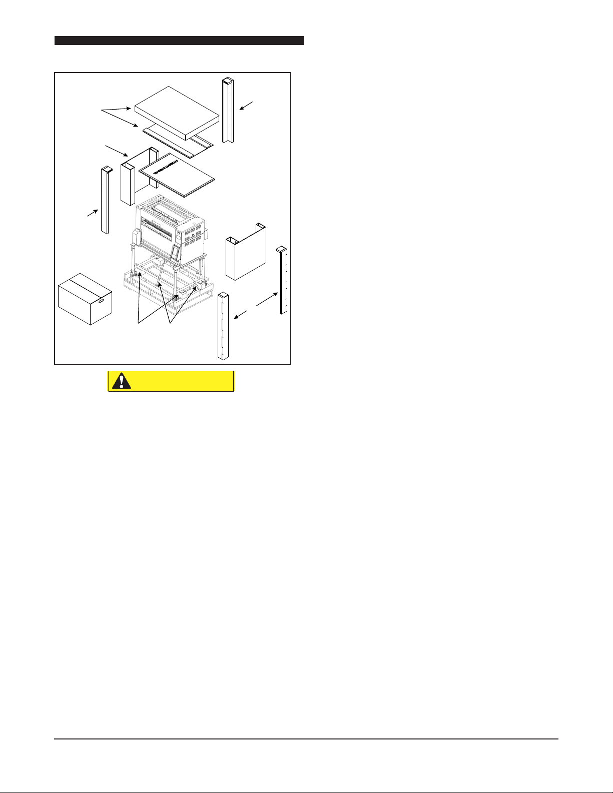
The broiler is very heavy!
Use adequate help when lifting.
6
4
1. Cut away the plastic outer wrap.
2. Remove the top cardboard and inner cap
(Item 2)
c. Gently lower the broiler to the oor to
avoid damage to casters
10. Remove the protective blue tape protecting
the broiler stainless steel panels. Verify all
blue tape is removed before installing and
operating the unit.
3. Remove training material box (Item 7)
4. Remove cardboard corner covers (Item 4)
5. Remove cardboard ends (Item 5)
6. Cut banding straps with a utility knife or
scissors (Items 6)
7. Remove accessories box (Item 8) checking
that no tape remains.
8. Lift one end of the broiler and tap the wood
block toward the center and then sideways
to remove. Repeat for the remaining blocks
allowing the casters to rest on the pallet.
9
Installation and Operation of Flexible Batch Broiler
With Touch Screen Control
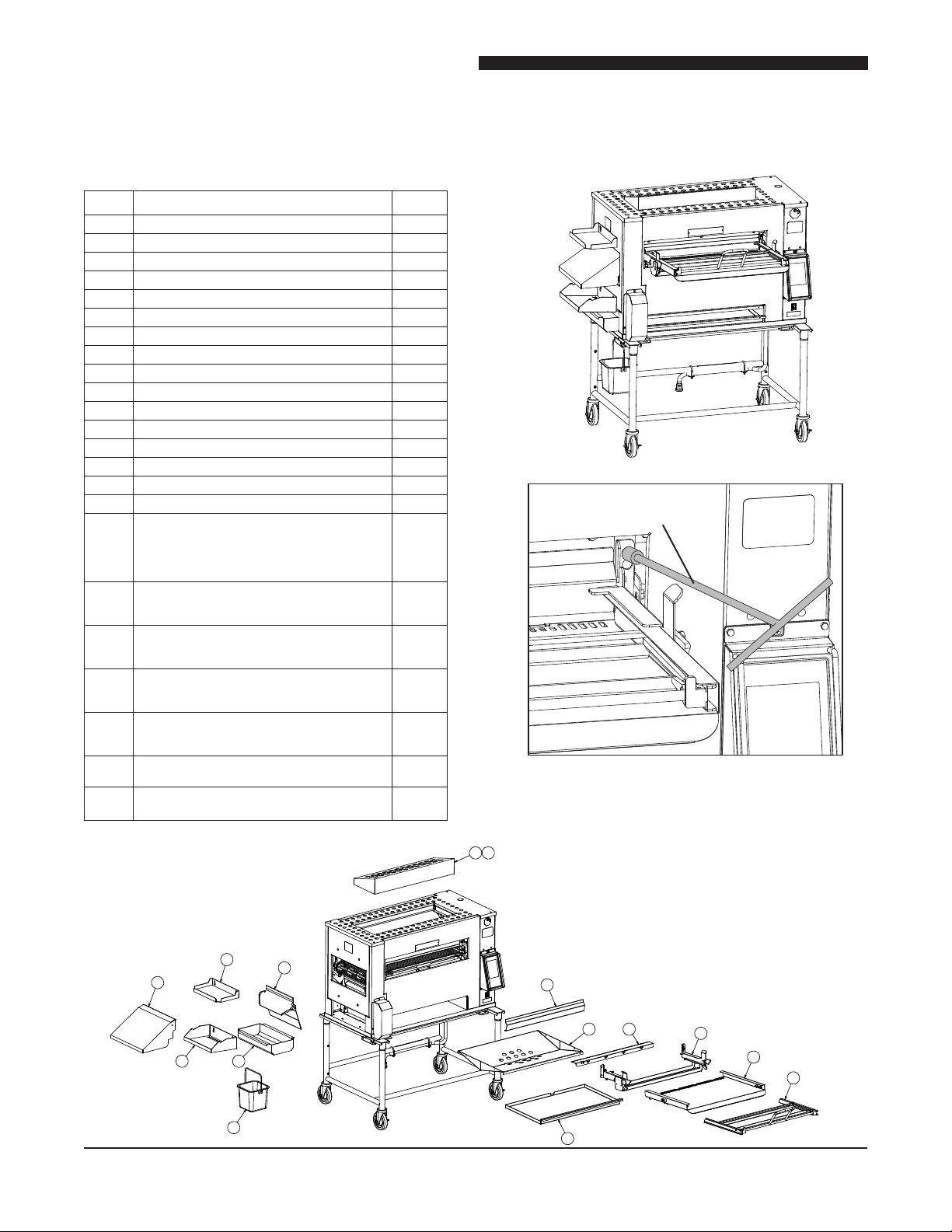
D. BROILER ASSEMBLY
Before assembling and installing the broiler, please
check to make sure that all necessary parts are present.
ITEM PART NAME
1 PRODUCT PAN SHELF 175353
2 DISCHARGE CHUTE 175340
3 DISCHARGE HOOD 175778
4 DISCHARGE PAN HOLDER 175358
5 DISCHARGE GREASE PAN 175357
6 “V” GREASE PAN 175325
7 MAIN GREASE PAN 175329
8 LOADER 175444
9 LOADER TRAY 175430
10 LOADER BRACKET 175438
11 DOOR 175429
12 LOADER RAMP 175741
13 IMPEDANCE PAN 175226
14 CATALYST (OPTIONAL) 175480
15 CATALYST GUARD (OPTIONAL) 175482
16 SANITATION PAIL 175842
17 KIT, CLEANING TOOLS/INSTALLATION
TOOL CLEANING – LOWER BURNER
FLAME ROD TUBE CLEANER BRUSH,
TUBE CLEANER TOOL– LOADER
INSTALL WRENCH, ALLEN, 3/16” 175700
18 KIT – BROILER SVC. PARTS,
NAT. GAS W/ CONTROLLER W/COOK
CHAIN (OPTIONAL)
19 KIT – BROILER SVC. PARTS, PROPANE,
W/ CONTROLLER W/COOK CHAIN
(OPTIONAL)
20 KIT – USER REPLACEABLE, BOTTOM
BURNER, FLAME ARRESTOR, LOADER &
BURNER SHIELD (OPTIONAL) 175726
21 KIT – USER REPLACEABLE, BOTTOM
BURNER & FLAME ARRESTOR
(OPTIONAL) 175750
22 KIT – GAS HOSE CONNECTOR
ASSEMBLY (OPTIONAL) 175690
23 KIT – HIGH SUPPLY GAS PRESSURE
REGULATOR (OPTIONAL) 175689
PT.NO.
Setup
Install all items as shown below.
Loader Install Tool
(Included with Broiler
Tools Kit)
Install loader bracket with (4) 1/4-20 nuts.
Use supplied extension tool to remove and reinstall nuts.
(Nuts are shipped installed on loader mounting studs.)
15
13
10
2
3
4
16
1
11
6 12
5
7
10
9
8
Installation and Operation of Flexible Batch Broiler
CAUTION
With Touch Screen Control
E. ADJUSTMENTS AT INSTALLATION
Each broiler section and all its component parts have
been tested thoroughly and inspected before your broiler
was shipped from the factory. However, it is sometimes
necessary to further test or adjust the broiler once it has
been installed. Such adjustments are the responsibility
of the Dealer or Installer. These types of adjustments
are not considered defects, rather a normal and routine
part of the proper installation of the equipment.
These adjustments include but are not limited to:
• Adjustments to the gas pressure regulator
• Broiler height adjustment (if required)
No installation should be considered complete without
proper inspection and, if necessary, any adjustments
by qualied service or installation personnel.
It is also important not to obstruct the natural ow of
combustion and ventilation air if the broiler is to operate
properly. This broiler should not be installed on a
curb base or sealed to the wall. Either condition can
restrict the ow of air to the combustion compartment
or prevent proper ventilation of the unit. Before making
any connections to the broiler, check the ratings plate
to be sure the broiler specications concur with the
type of gas and voltage to be supplied to the broiler.
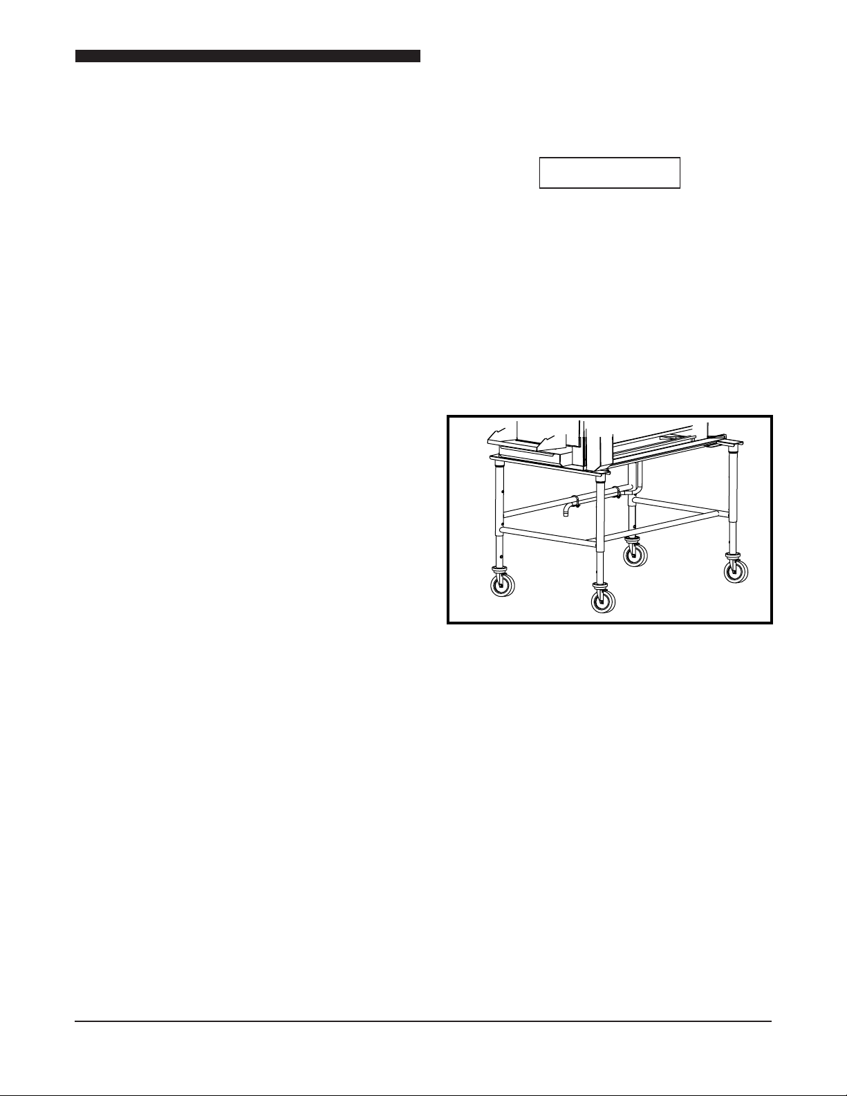
Raise or Lower Broiler
The broiler height can be adjusted via two screws on
each leg.
The Broiler is very heavy! Use adequate
help for lifting.
1. Lift one end of the broiler onto a wide, sturdy stand
(not supplied).
2. Remove (2) screws per leg and raise/lower to
threaded holes. Reinstall screws.
3. Remove stand and safely raise/lower broiler.
4. Place plastic hole plugs (supplied attach to stand)
in any unused holes.
The rating plate is located on the back of the control
compartment cover panel on the right end of the unit.
The plate bearing the broiler’s model number and serial
number is attached to the back side of the unit.
11
 Loading...