

Duke 59-EV Service Manual
5/9 THE OVEN
ELECTRIC HALF – SIZE
CONVECTION OVEN
Installation, Operation, Parts
& Maintenance Manual
DUKE MANUFACTURING CO.
2305 N. Broadway • St. Louis, MO 63102
800.735.3853 • 314.231.1130 • 314.231.5074 Fax
www.dukemfg.com
155131P
INDEX
PAGE
5/9 Electric Specifications 3
Installation Instructions
A. Qualified Personnel
B. Delivery & Inspection 4
C. Location of Oven 4
D. Electrical Connections 4-5
E. Oven Assembly 5
F. Adjustments Associated with Installation 5
Operating Instructions
A. Oven Controls
B. General Guidelines for Operation 26
C. Suggested Times & Temperatures 27
D. Cook & Hold – Roast & Hold 28
4
6-25
Maintenance Instructions
A. Adjustments 29
B. Door Adjustment 29
C. Door Switch Adjustment 29
D. Thermostat Calibration 29-30
E. Cleaning the Oven 30
Repair Parts List 31
Door Assembly 32
“V” Controller Assembly 33
“X” Controller Assembly 34
“Z” Controller Assembly 35
“XX” Controller Assembly 36
“ZX” Controller Assembly 37
“ZZ” Controller Assembly 38
Contactor Identification 39
Flue Guard 40
Double Stack Ovens 40
Wiring Diagrams 42 - 51
Please supply the ID Number and the Serial Number when
ordering replacement parts or requesting service.
2 of 52
We recommend service by Duke Authorized Service
Agencies during and after the warranty period.
FOR YOUR SAFETY:
Do not store gasoline or other flammable vapors or liquids in the vicinity of this or
any other appliance.
WARNING:
Improper installation, adjustment, alteration, service or maintenance can cause
property damage, injury or death. Read the installation, operating and maintenance
instructions thoroughly before installing or servicing this equipment.
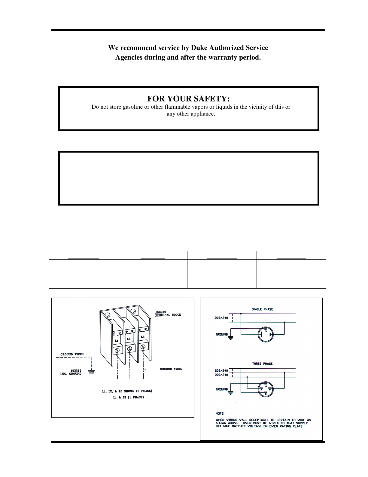
ELECTRICAL SPECIFICATIONS
Total KW VOLTS 1 PHASE 3 PHASE
8.0 208 41.0 24.0 amps/pl
8.0 240 36.0 21.0 amps/pl
Power Supply Connections
3 of 52
INSTALLATION INSTRUCTIONS:
A. Qualified Personnel
These installation instructions are for the use of
qualified installation and service personnel only.
Installation or service by other than qualified personnel
may result in damage to the oven and/or injury to the
operator.
Qualified installation personnel are those individuals,
firms, companies or corporations which either in person
or through an agent is engaged in and responsible for:
• The installation of electrical wiring from the
electric meter, main control box or service outlet
to the electrical appliance. Qualified installation
personnel must be familiar with all precautions
required and have complied with all
requirements of state and local authorities having
jurisdiction. See: National Electrical Code,
ANSI/NFPA70.
B. Delivery and Inspection
Duke Manufacturing Co. does everything within its
power to insure you received your oven in good
condition. They are strapped down on heavy wooden
skids and surrounded by heavy "tri-wall" cartons to
prevent shipping damage. They have all been carefully
inspected before they were packaged and consigned to
the carrier.
Upon delivery of your Duke oven:
• Look over the shipping container, carefully noting
any exterior damage on the delivery receipt,
which must also be signed by the driver/ delivery
person.
• Uncrate and check for any damage, which was not
evident on the outside of the shipping container.
This is called concealed damage. The carrier must
be notified within fifteen (15) days of the delivery
of the oven and the carton, skid and all packaging
materials must be retained for inspection.
Duke Manufacturing Co. cannot assume liability for
loss or damage suffered in transit. The carrier assumes
full responsibility for delivery in good order when the
shipment was accepted. However, we are prepared to
assist you in filing your claim.
C. Location of the Oven
Proper planning and placement of the oven will give
you the best results in terms of long-term user
convenience and satisfactory performance. We urge you
to give adequate thought in the placement of your oven
prior to its arrival.
• The oven should be placed in an area that is free
from drafts and accessible for proper operation
and servicing.
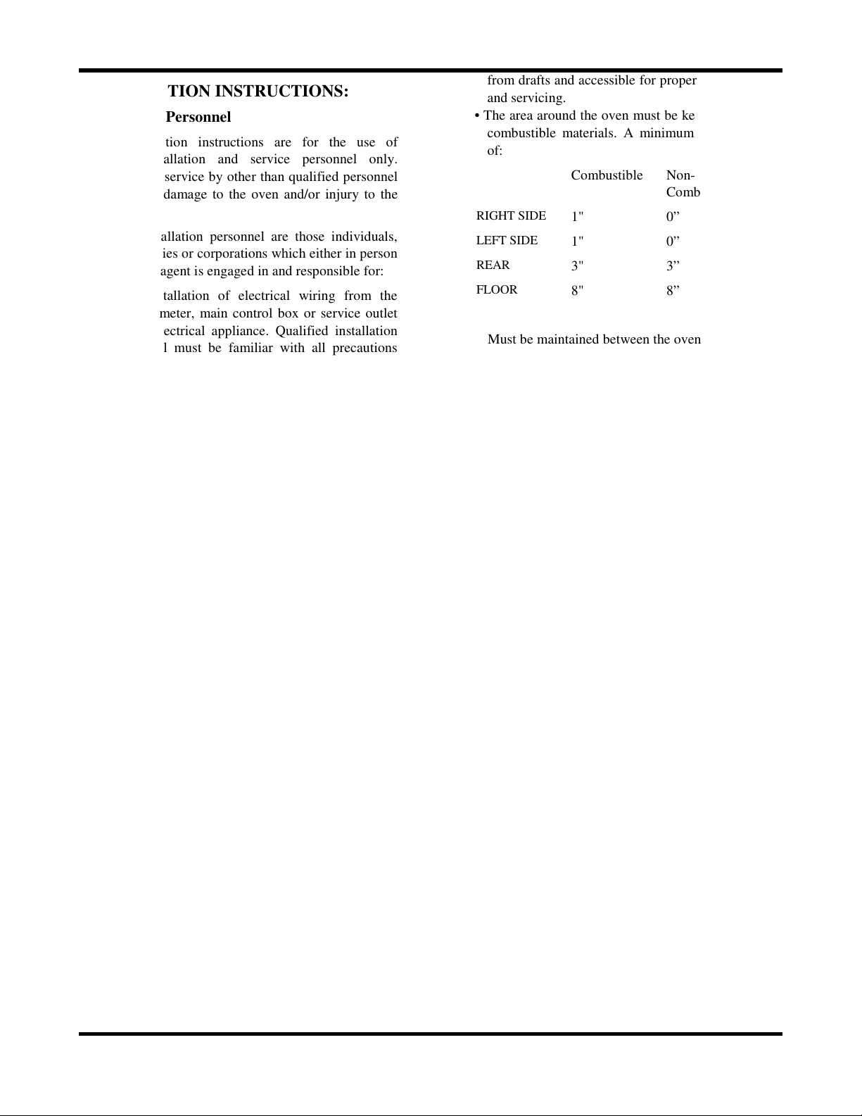
• The area around the oven must be kept clear of
combustible materials. A minimum clearance
of:
Combustible Non-
Combustible
RIGHT SIDE
LEFT SIDE
REAR
FLOOR
1" 0”
1" 0”
3" 3”
8" 8”
Must be maintained between the oven and any
combustible or non-combustible surface.
It is also important not to obstruct the natural flow
of ventilation air if the oven is to operate properly.
This oven should not be installed on a curb base or
sealed to the wall. Either condition can restrict the
flow of air to or prevent proper ventilation of the
blower motor. The blower motor has a thermal
protection device, which will trip, because of
excessive ambient temperatures at the back of the
oven. This condition should be corrected
immediately to avoid damaging the oven
permanently.
The flue located near the top at the rear of the oven
must not be obstructed. Proper ventilation is
important to avoid high temperatures at the rear of
the oven. High temperatures can cause premature
blower motor failure.
Before making any connections to the oven, check
the rating plates to be sure the oven specifications
concur with the voltage and phase to be supplied to
the oven.
The rating plate is located behind the lower front
panel. To access, loosen the four screws below the
doors, and pull the panel outward.
The plate bearing the oven’s serial number is
attached to the underside of the upper ledge above
the control panel.
D. Electrical Connections
Your oven is supplied for connection to a 208, 240,
440 or 480 volt grounded circuit. The electric
motor, oven lights, indicator lights and control
circuits are connected internally and require no
secondary power supply.
Before making any connections to these units, check
the rating plate to assure that the voltage and phase
4 of 52
of the oven is compatible with the electrical supply.
When installing, all ovens must be electrically grounded
in accordance with local codes or in the absence of local
codes, with the National Electrical Code, ANSI/NFPA
70 (in Canada – CSA Std. C22.1). Wiring diagrams are
located in the control compartment area. Standard
wiring schematics are also included at the back of this
manual.
The proper method of connecting the power source to
the terminal block is shown in the Exploded Views
Section.
Note to Electrical Inspector:
Inspection of electrical connection should be
accomplished by the removal of the Control Panel.
E. Oven Assembly
Before assembling and installing the oven, please check
to make sure that all necessary parts are present. In
addition to the oven itself, there will also be legs, feet or
casters, the vent guard, (for double sections, retaining
clips, vent riser) and miscellaneous hardware. Please
check the interior of all oven sections for the parts
needed to assemble and install your oven(s).
Leg Attachment
• Once the oven has been removed from the
carton, lay it on its lift side (the side without
the controls).
• Position one of the legs against the bottom of
the oven, aligning the center hole on the leg
plate with the center threaded hold on the
bottom of the oven.
• While supporting the leg, carefully start the
bolt in the center hole and finger tighten.
(Avoid cross threading.)
• Align the other two leg plate holes with those
in the bottom of the oven.
• Carefully start the bolts in the remaining holes
and finger tighten. (Avoid cross threading.)
• Secure each of the bolts using a wrench.
• Repeat this process for all legs.
• Addt the two (2) storage shelves between the
four (4) legs and secure with the bolts
provided.
• Raise the oven up on the legs.
Caster Installation
Casters are available as an option for double oven
sections. They are packed inside the oven for shipment.
• Place the tip of a large screwdriver against the
lip of the adjustable foot on the bottom of the
leg.
• Using a hammer, drive the foot out of the leg.
• Insert the caster fully into the opening where
the foot came out.
• Using a wrench, tighten the locking nut on the
bottom of the caster to expand the
compression sleeve until secure.
• Repeat this process for the remaining legs.
NOTE: The casters with locking brakes are best
mounted on the front side of the oven for easier
access.
NOTE: If you plan to use casters, a fixed restraint of
the proper length is recommended to eliminate
strain on the connecting wire. If the oven is removed
from its normal position, the restraint must then be
reattached when returned.
F. Adjustments Associated with Installation
Each oven section and all its component parts have
been tested thoroughly and inspected before your oven
was shipped from the factory. However, it is sometimes
necessary to further test or adjust the oven once it has
been installed. Such adjustments are the responsibility
of the Dealer or Installer. These types of adjustments
are not considered defects, rather a normal and routine
part of the proper installation of the equipment.
These adjustments include but are not limited to:
• Adjustments and recalibration of the thermostat
• Adjustment to the doors.
• Leveling.
• Tightening of fasteners.
No installation should be considered complete
without proper inspection and, if necessary, any
adjustments by qualified service or installation
personnel.
Level the oven by turning the adjustable feet in or out as
needed.
5 of 52
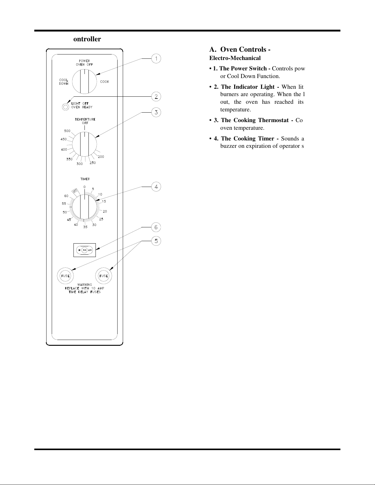
V” Controller
A. Oven Controls -
Electro-Mechanical
• 1. The Power Switch - Controls power to ON
or Cool Down Function.
• 2. The Indicator Light - When lit indicates
burners are operating. When the light goes
out, the oven has reached its cooking
temperature.
• 3. The Cooking Thermostat - Controls the
oven temperature.
• 4. The Cooking Timer - Sounds an electric
buzzer on expiration of operator set time as
a reminder to remove product at end of
cooking cycle.
• 5. The Fuse Holders – Contain circuit
protecting fuses.
• 6. The Fan Speed Switch (Optional) - Sets
fan speed to high or low.
6 of 52
Operating Instructions - “V” Controller
Timer Resolution
The Timer displays time from 0 to 60 minutes, in one-
minute increments.
Temperature Scale
The Temperature Control displays the temperature in
°F. The temperature range is from 150°F - 500°F, in
25°F increments.
Cool Down
This feature enables the oven to be cooled rapidly by
allowing the fan to operate with the heating elements
turned off. To activate, turn the Power Switch to the
COOL position and open the oven door. When the
door is opened enough to disengage the door switch,
the fan will turn on. Closing the door will turn the fan
off.
Fan Speed Switch
The fan speed can be set to high or low speed by
placing the FAN HI/LOW button to the desired setting.
Cooking
A cooking cycle can be initiated as follows:
• Turn the Power Switch to COOK position.
• Set the Cooking Temperature by turning the
TEMPERATURE dial to the desired
temperature. The OVEN READY indicator
light will turn on.
• When the OVEN READY indicator light turns
off, place the product to be cooked in the
oven.
• Set the cooking Time by turning the COOK
TIMER dial to the desired time.
During the Cook Cycle, The OVEN READY Indicator
light will cycle on and off with the heating elements.
• When the COOK TIMER reaches “zero”, the
alarm will sound.
• To cancel the alarm, turn the COOK TIMER
dial to the OFF position.
7 of 52
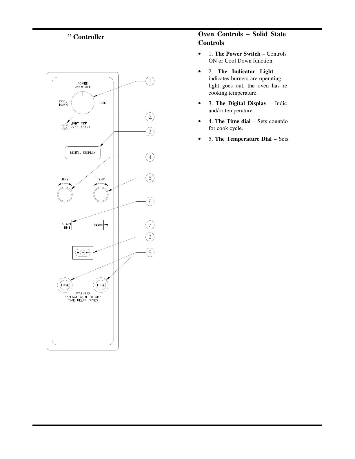
“X” Controller
Oven Controls – Solid State Digital
Controls
• 1. The Power Switch – Controls power to
ON or Cool Down function.
• 2. The Indicator Light – When lit
indicates burners are operating. When the
light goes out, the oven has reached its
cooking temperature.
• 3. The Digital Display – Indicates time
and/or temperature.
• 4. The Time dial – Sets countdown timer
for cook cycle.
• 5. The Temperature Dial – Sets cooking
temperature.
• 6. The Start Time Button – Initiates
timing cycle.
• 7. The Cancel Button – Cancels preset
time and/or temperature.
• 8. The Fuse Holders – Contain circuit
protecting fuses.
• 9. The Fan Speed Switch (Optional) –
Sets fan speed to high or low.
8 of 52
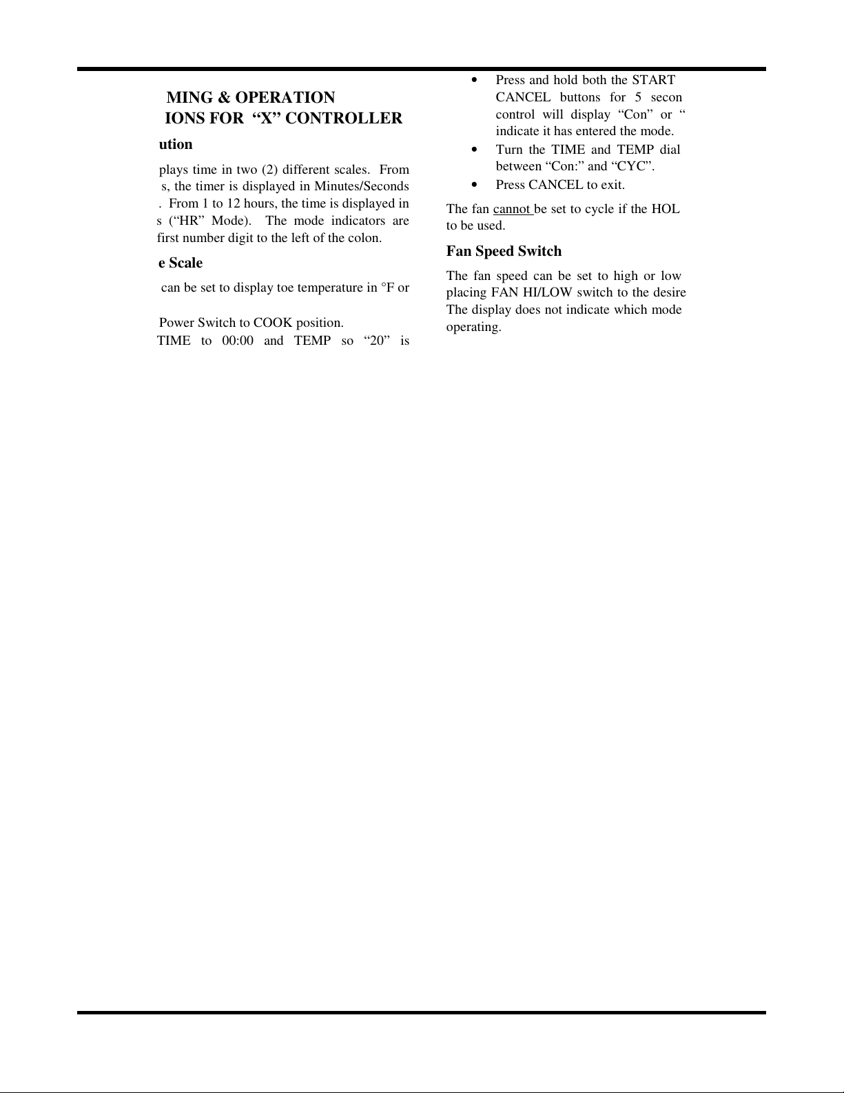
PROGRAMMING & OPERATION
INSTRUCTIONS FOR “X” CONTROLLER
Timer Resolution
The Timer displays time in two (2) different scales. From
0 to 60 minutes, the timer is displayed in Minutes/Seconds
(“MN” Mode). From 1 to 12 hours, the time is displayed in
Hours/Minutes (“HR” Mode). The mode indicators are
located in the first number digit to the left of the colon.
Temperature Scale
The controller can be set to display toe temperature in °F or
°C as follows:
• Turn Power Switch to COOK position.
• Set TIME to 00:00 and TEMP so “20” is
displayed in the right two temperature digits.
• Press and hold both the START TIME and
CANCEL buttons for 5 seconds. The control will
display “CCC” and “FFF” in the temperature
digits to indicate it has entered the mode.
• Turn the TIME or TEMP dial to toggle
between “CCC” and “FFF”.
• Press CANCEL to exit.
Power Input Frequency
The controller can be set to operate on 50Hz or 60Hz as
follows:
• Turn Power Switch to COOK position.
• Set TIME to 00:00 and TEMP so “40” is
displayed in the right two temperature digits.
• Press and hold both the START TIME and
CANCEL buttons for 5 seconds. The control
will display “50” and “60” to indicate it has
entered the mode.
• Turn the TIME or TEMP dial to toggle
between “50” and “60”.
• Press CANCEL to exit.
Actual Temperature Button
The actual temperature can be viewed by pressing and
holding the START TIME button for approximately 2
seconds. The temperature will be displayed in the
temperature digits. This can be viewed anytime the
oven is in operation, except when the oven is in the
HOLD mode.
• Press and hold both the START TIME and
CANCEL buttons for 5 seconds. The
control will display “Con” or “CYC” to
indicate it has entered the mode.
• Turn the TIME and TEMP dial to toggle
between “Con:” and “CYC”.
• Press CANCEL to exit.
The fan cannot be set to cycle if the HOLD mode is
to be used.
Fan Speed Switch
The fan speed can be set to high or low speed by
placing FAN HI/LOW switch to the desired setting.
The display does not indicate which mode the fan is
operating.
Cool Down
This feature enables the oven to be cooled rapidly
by allowing the fan to operate with the burners
turned off. To activate, turn the Power Switch to the
COOL position and open the oven door. When the
door is opened enough to disengage the door switch,
the fan will turn on. Closing the door will turn the
fan off.
Cooking
A cooking cycle can be initiated as follows:
• Turn Power Switch to COOK position.
• Set the cooking time by turning the TIME
dial until the desired time is shown on the
display.
• Set the desired cooking temperature by
turning the TEMP dial until the desired
temperature is shown on the display. The
indicator light will turn on and the display
will flash when a minimum temperature of
150°F is entered. The flashing display
indicates that the oven is in its Preheating
Mode. It will no longer flash once the
oven reaches the temperature set point.
The indicator light will cycle on and off
with the burners.
• Press the START TIME button to begin the
timed cooking cycle. Pressing the
CANCEL button will “zero” the timer at
any time.
Pulse
The controller can be set to operate the fan
continuously, or cycle on and off every 30 seconds
during the COOK cycle as follows:
• Turn Power Switch to COOK position.
• Set TIME to 00:00 and TEMP to 000.
Cook & Hold
The controller can be set to hold the oven at a set
temperature at the end of the cooking cycle as
follows:
• Turn Power Switch to COOK position.
• Set TIME to 00:00 and TEMP so “50” is
displayed in the right two temperature
9 of 52
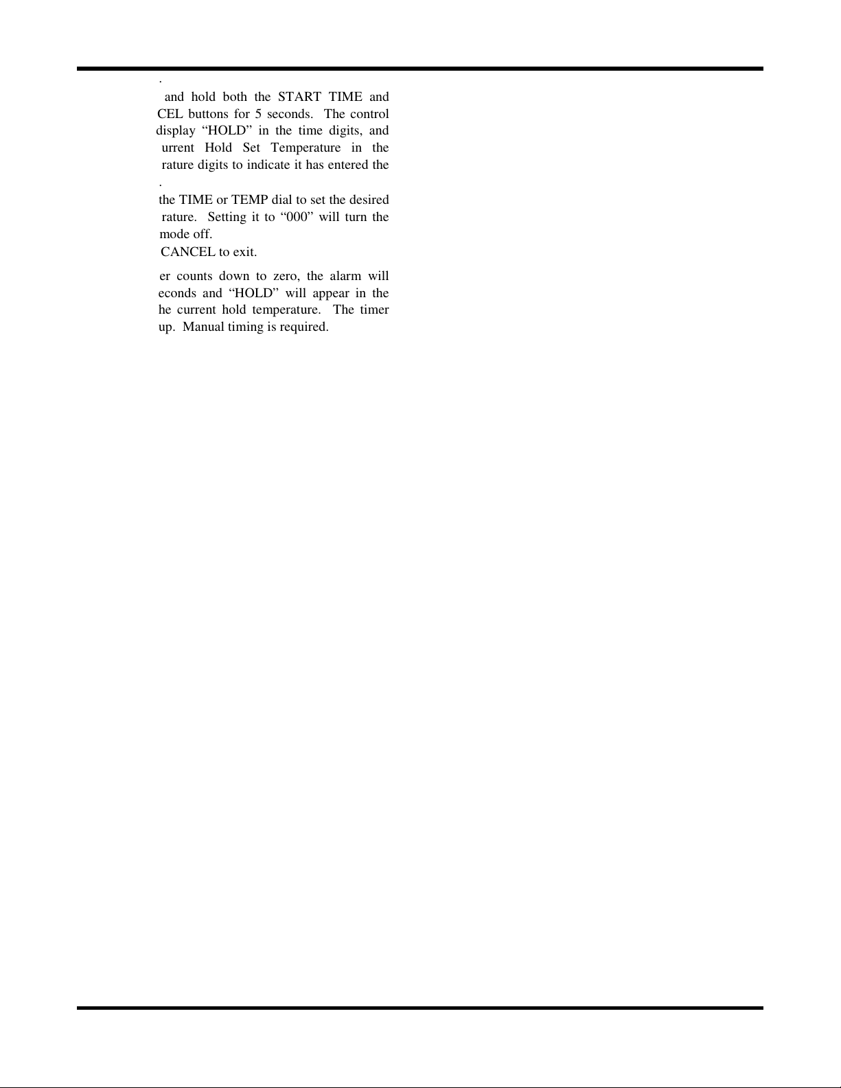
digits.
• Press and hold both the START TIME and
CANCEL buttons for 5 seconds. The control
will display “HOLD” in the time digits, and
the current Hold Set Temperature in the
temperature digits to indicate it has entered the
mode.
• Turn the TIME or TEMP dial to set the desired
temperature. Setting it to “000” will turn the
Hold mode off.
• Press CANCEL to exit.
When the timer counts down to zero, the alarm will
sound for 5 seconds and “HOLD” will appear in the
display with the current hold temperature. The timer
will not count up. Manual timing is required.
Offset
To compensate for the difference in temperature from
the sensing element to the center of the oven the control
can be programmed with an offset. The offset is
adjustable in 1ºF increments up to a maximum of
±49ºF.
Note: a negative offset will have the effect of raising
the cavity temperature, (Example: an oven set at 375ºF
is determined to run at a 350ºF internal oven
temperature. By programming in a -25ºF offset the
oven will run at a 375ºF internal oven temperature.).
The offset is programmed as follows:
• Turn Power Switch to COOK position.
• Set TIME to 00:00 and TEMP so “10” is
displayed in the right two temperature digits.
• Press and hold both the START TIME and
CANCEL buttons for 5 seconds. The control
will display “UPO” in the time digits, and the
current Offset in the temperature digits to
indicate it has entered the mode.
• Turn the TIME or TEMP dial to raise or lower
the offset.
• Press CANCEL to exit.
10 of 52
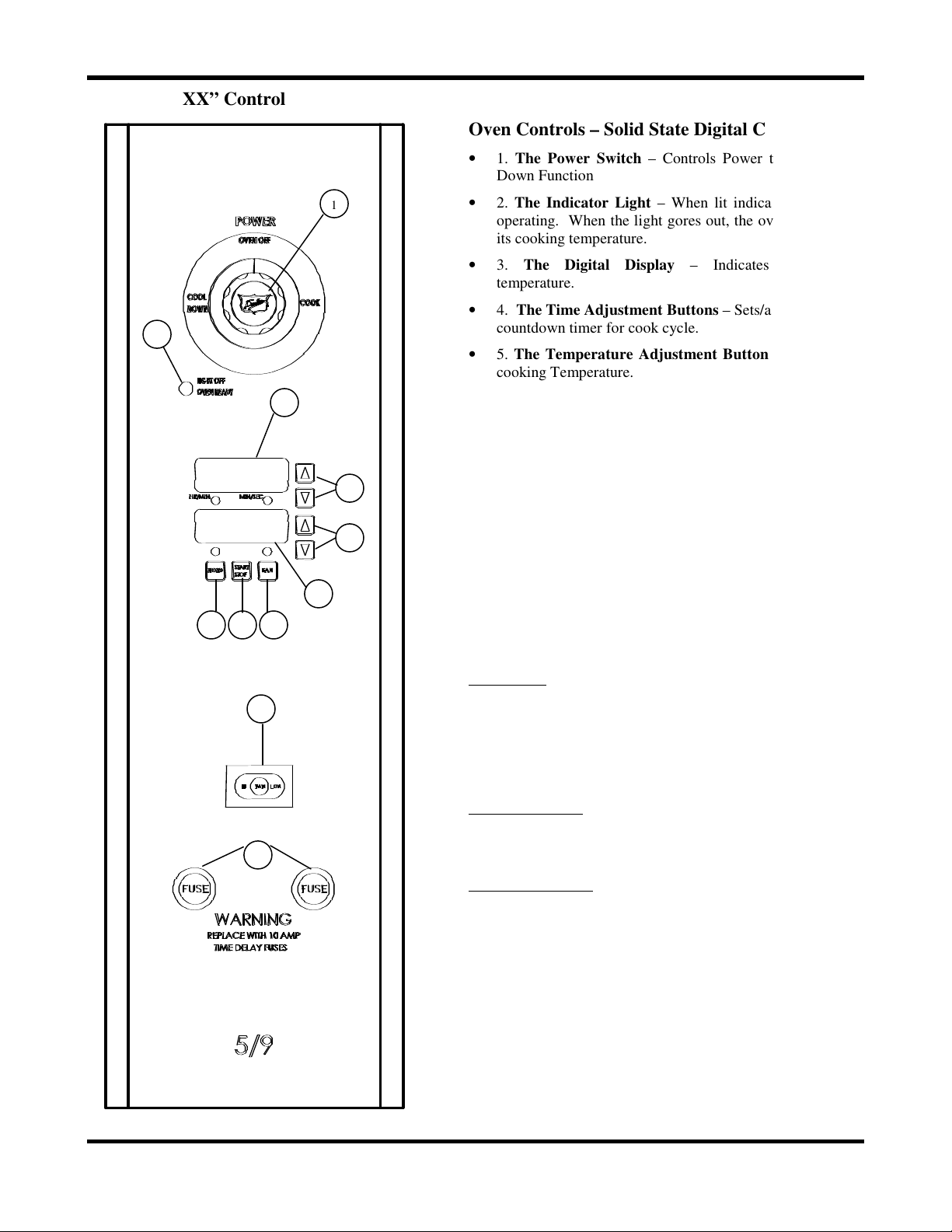
“XX” Control
Oven Controls – Solid State Digital Controls
• 1. The Power Switch – Controls Power to ON or Cool
Down Function
• 2. The Indicator Light – When lit indicates burners are
operating. When the light gores out, the oven has reached
its cooking temperature.
• 3. The Digital Display – Indicates time and/or
temperature.
• 4. The Time Adjustment Buttons – Sets/adjusts
countdown timer for cook cycle.
• 5. The Temperature Adjustment Buttons – Sets/adjusts
cooking Temperature.
• 6. The Temperature Digital Display: Displays the
temperature inside the oven.
• 7. The Pulse Fan Button: Enables/Disables the Pulse Fan
Function.
• 8. The Start/Stop Button: Starts/Stops the cooking cycle.
• 9. The Hold Button: Enables/Disables the Hold Function.
• 10. The Fan Speed Switch: (Optional) – Sets fan speed to
high or low.
• 11. The Fuse Holders: Each holds a 10 AMP Time Delay
Fuse.
Programming and Operating Instructions –
“XX” Controller
Timer Scale: The Timer displays in two (2) different scales.
From 0 to 60 minutes, the timer is displayed in
Minutes/Seconds. This is indicated by the MIN/SEC light on
the controller. From 1 to 2 hours, the time is displayed in
Hours/Minutes, indicated by the HOUR/MIN light on the
controller. When the oven is first turned on, the display will
show the last cook time programmed.
Time Adjustment: To increase the cook time, press the top (▲)
button located next to the Time Display. To decrease the cook
time, press the bottom button (▼) located next to the Time
Display.
Temperature Scale: The controller can be set to display the
temperature in ºF or °C as follows:
1) Remove/move control panel so that you have access to the
back of the control board.
2) Locate the blue jumper at connection J3.
3) For °F operation the jumper is not needed. Place the jumper
on one of the pins for future use.
4) For °C operation place the jumper across the two pins of J3.
When the oven is first turned on, the display will show the last
cook temperature programmed. You can view the actual
temperature of the oven by pressing both of the Temperature
Adjustment buttons at the same time.
11 of 52
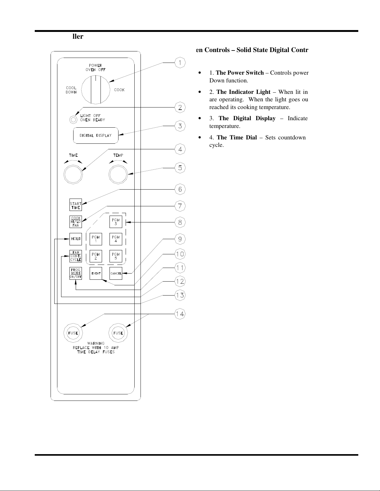
“Z” Controller
Oven Controls – Solid State Digital Controls
• 1. The Power Switch – Controls power to ON or Cool
Down function.
• 2. The Indicator Light – When lit indicates burners
are operating. When the light goes out, the oven has
reached its cooking temperature.
• 3. The Digital Display – Indicates time and/or
temperature.
• 4. The Time Dial – Sets countdown timer for cook
cycle.
• 5. The Temperature Dial – Sets cooking
temperature.
• 6. The Start Time Button – Initiates timing cycle.
• 7. The Cook/HI-LO Button – Sets fan speed to high
or low.
• 8. The Program Button – 5 individual time and
temperature programs. Operator programmed.
• 9. The Cancel Button – Cancels preset time and/or
temperature.
• 10. The Event Button – Used for programming oven
functions that will be chained into one cooking
routine.
• 11. The Program Mode – ON/OFF – Switches from
Operating to Programming Mode and back.
• 12. The Fan Continuous/Cycle Button – Allows
setting of fan to run continuously or turn on and off
with the burners during the cooking cycle.
• 13. The Hold Button – Allows setting of hold time
and temperature.
• 14. The Fuse Holders – Contain circuit protecting
fuses..
12 of 52
PROGRAMMING & OPERATING
INSTRUCTIONS“Z” CONTROLLER -
This controller provides five (5) automatic cooking
chains, which the user can program. It will also a low
non-automatic cooking and cook & hold operations.
The fan motor can be controlled to cycle on and off
with the burners or run continuously. High or low fan
speeds can be selected.
The cooking chains are particularly useful when the
user is producing batches of the same product time
after time, especially if changes to temperature or fan
speed are required during the cooking cycle. The user
can program one of the five program buttons for a
particular product and simply press one button when
it is loaded into the oven. The control will follow the
programmed cooking routine changing temperate
and/or fan speeds or fan cycle/continuous at the
programmed intervals. Thus, once the cooking chain
is programmed, the user would benefit from
consistent results when cooking the same batch.
However, not all usage of the oven requires an
automatic cooking routine. In these cases, the oven
can be used in a normal manner where the times and
temperatures are set using the rotary dials. A manual
Cook & Hold is also available for holding a product
after it has been cooked.
The following instructions will assist you in using this
control with your oven, but if you have any questions
you should contact the Duke Service Department on
our toll free support line: 800.735.3853.
Timer Resolution
The Timer displays time in two different scales.
From 0 to 60 minutes, the time is displayed in
Minutes/Seconds (“MN” Mode). From 1 to 12 hours,
the time is displayed in Hours/Minutes (“HR” Mode).
The mode indicators are located in the firs number
digit to the left of the colon.
Power Input Frequency
The control will display “CCC” or “FFF” in the temperature digits
to indicate it has entered the mode.
Entering will toggle between “CCC” and “FFF”. Pressing and
holding the START TIME button again will also toggle the setting.
Turn Power Switch to OFF position to exit.
Time Dial
The TIME dial sets time intervals for cooking. It is used in either
programmed or manual cooking.
Temp Dial
The TEMP dial sets the temperature. The temperature changes in
5°F or 1°C increments.
Start Time Button
The START TIME button initiates the cooking cycle whether a
programmed chain or manual time set with the TIME dial used.
Cook HI/LO Fan Button
The COOK HI/LOW FAN button puts the control into a cook mode
and enables the heating elements. Each time the button is pressed,
the control switches between the high or low fan speeds. If neither
fan is enabled, the high fan speed is selected automatically. The HI
FAN and LO FAN indicators show, which fan speed, is selected.
Hold Button
The HOLD button is used to set up the Hold Mode. The user
presses the HOLD button and sets the desired temperature and
continuous or cycled fan. During the Hold setup mode, the HOLD
indicator is lit and the CYCLE indicator is lit if the cycled fan is
selected.
During the cook portion hold mode, the timer counts down to zero.
During the hold portion, the timer counts up from zero.
Fan Con/Cyc Button
The FAN CON/CYC button enables the fan to run continuously
during the cooking cycle, or run only when the control is calling for
heat. The display will show FAN CYC when the cycled fan mode
is selected and FAN CON when the continuous mode is selected.
The CYCLE indicator will light when the cycled fan is enabled.
The controller will automatically set itself to operate
on 50Hz or 60Hz, depending on the power source
used. All timers and internal clocks are automatically
compensated.
Temperature Scale
The controller can be set to display the temperature in
°F or °C. as follows:
• Turn Power Switch to COOK position.
• Set TIME to 00:00 and TEMP so “20” is
displayed in the right two temperature digits.
Press and hold the START TIME button for 5 seconds.
13 of 52
Program Mode On/Off Button
Manual Cooking
This button allows the user to activate the
programming mode. When this mode is selected,
normal oven operation is suspended. The
programming mode allows the user to program the
cook chains. When this button is pressed again, the
program mode is exited and normal oven operation is
resumed. When the programming mode is entered the
PGM indicators flash.
Event # Button
During the programmed chain cooking operation, this
button is used to recall the time remaining in the
current event. In the programming mode, this button
is used to sequence to the next event to be
programmed. During manual operation, this button is
disabled.
Program Buttons (1-5)
The five (5) programming buttons are provided for
chained cooking. Programs 1 and 2 provide the user
with 6 events each, and programs 3, 4 and 5 provide 4
events each. The user sets the value programmed for
each event. The Program buttons are locked out when
the control is running a manual timed cook.
1 Event = time, temp, fan speed, fan mode.
Cancel Button
The CANCEL button is provided to clear the timer
and enable the program buttons and rotary dials. It
also cancels the Programming Mode, the beeper, and
turns off any indicators that are no longer needed.
Power Up
On initial power up, the time digits will always
display zeros with a colon. The temperature digits
will display zeros with the degree (°) indicator lit.
The C will also be lit in the display if the Celsius
option is selected. When the control is turned off, the
temperature/timer setting is stored. When the control
is turned on again, it will automatically return to the
last set time and temperature
A normal, non-programmed cooking cycle can be initiated as
follows:
• Turn Power Switch to COOK position.
• Set the desired time using the TIME dial.
• Set the desired temperature using the TEMP dial.
• Select the desired fan speed using the COOK HI/LO FAN
button.
• Select the fan to be on continuously or cycled using the
FAN/ CON/CYC button.
• Set the HOLD temperature, if desired.
• Press the START TIME button to start the cooking cycle.
• Pressing the CANCEL button will “zero” the Timer at any
time.
Programmed Chain Cooking
With the control in normal operating mode, press the desired chain
(PBM 1-5) button. If the selected chain has been programmed, the
first event will be loaded. The timer will not start until the START
TIME button is pressed. The oven temperature will be controlled to
the temperature programmed to the first event.
Chain Programming
Each of the 5 PGM buttons can be programmed to perform a
different sequence or “chain” of events. Each event, or step,
includes a setting for the time, temperature, fan speed, and fan
mode. PGM 1 and PGM 2 allow the user to set up to 6 events to
be performed during the cooking cycle, while PGM 3,
PGM 4 and PGM 5 allow up to 4 events. The last event for any
of the Programmed Chains can be set to be a Hold mode.
Programming the PGM buttons is performed as follows:
• Turn Power Switch to COOK position.
• Press the PGM MOD ON/OFF button to enter the
programming mode. All PGM indicators will flash and
the balance of the display will be blanked.
• At this time, one of the PGM Button’s (1-5) must be
pressed to select which chain is to be programmed. When
the desired PGM button is pressed, the appropriate PGM
indicator will remain flashing and event 1 time and
temperature will be displayed. The event number (E1-E6)
will be displayed alternately with the temperature digits.
Cool Down
This feature enables the oven to be cooled rapidly by
allowing the fan to operate with the heating elements
turned off. To activate, turn the Power Switch to the
COOL position and open the oven door. Then the
door is opened enough to disengage the door switch,
the fan will turn on. Closing the door will turn the fan
off.
14 of 52
• To change the event time, turn the TIME
dial. The time entered will be displayed in
the time digits.
• To change event temperature, turn the
TEMP dial for the desired set temperature.
The temperature entered will be displayed in
the temperature digits. The event number
display will not be shown while the TEMP
dial is being rotated.
• To change the fan speed, press the COOK
HI/LO FAN button. The display indicators
will show the selected cook mode.
• Press the FAN CON/CYC button to select
continuous or cycled fan. The display will
show FAN CON or FAN CYC to indicate
which mode is selected. The CYCLE
indicator will light if the cycled fan is
enabled.
• To set up a hold mode, press the HOLD
button. The HOLD indicator will be lit
when this mode has been selected.
When an event is programmed as a Hold,
that event will be the last recognized event
of the chain. As an example, if Event 3 is
set up as a Hold and Event 4 was set up as
a Cook, Event 4 would be ignored.
• To exit the Programming mode, press the
PGM ON/OFF or CANCEL button. The
programmed parameters of the previously
programmed chain will be saved at this time.
• To program another event within the same
chain, press the EVENT # button. The
parameters of the previous event are saved at
this time and sequential event will be
displayed. If the previous event was the last
of the chain, the first event will be displayed.
• To program another chain, press the desired
PGM BUTTON (1-5). Event 1 of the
selected chain will be displayed and the
parameters of the previously programmed
chain will be saved at this time.
EXAMPLE: MUFFINS
Event 1
cook time = 4 minutes
Cycled, low fan allows the muffins to rise and skin over
without being distorted by the air movement.
Event 2
continuous fan, cook time = 8 minutes.
Once the product is skinned over, the continuous, highspeed fan will finish the cooking.
TOTAL COOK TIME = 12 MINUTES
(This is an example; your results may vary.)
: Cook temp - 400°F, LOW fan speed, cycled fan,
: Cook temp = 400°F, HIGH fan speed,
15 of 52
 Loading...