

Duke 59-E3P Parts List
DUKE MANUFACTURING CO. 155409E
POPEYE’S
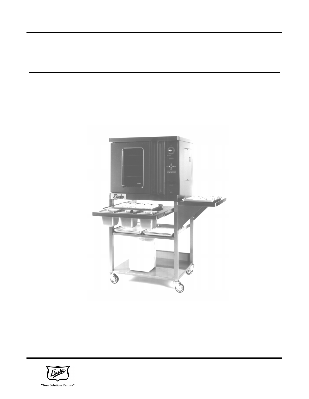
Duke 59-E3P
ELECTRIC HALF-SIZE
CONVECTION OVEN
Installation, Operation, Parts
& Maintenance Manual
1111
2305 N. Broadway, St. Louis, MO 63102 155433P
800-735-3853 •••• 314-231-1130 •••• 314-231-5074 FAX:
www.dukemfg.com

We recommend service by Duke A
uthorized Service
INDEX
59-E3P Electrical Specifications 4
Installation Instructions
A. Qualified Personnel 5
B. Delivery & Inspection 5
C. Location of Oven 5
D. Electrical Connections 5-6
E. Ventilation 6
F. Electric Oven Assembly 6
G. Adjustments Associated with Installation 6
Control Panel 7
A. Program Parameters 8
B. Programming Instructions 8-9
C. Operation of Oven 9
D. Cool Down Operation 9
E. Emergency Back-Up System 10
F. Troubleshooting 10
G. Control Failure Diagnostics 11
Cleaning the Oven 12
Maintenance Instructions 13
A. Adjustments 13
B. Door Adjustments 13
C. Lubrication 13
D. Calibration Check 13
Repair Parts List and Corresponding Drawings 14-19
Wiring Diagram 20-22
Please supply the Model Number and the Serial Number when
ordering replacement parts or requesting service.
Agencies during and after the warranty period.
3 of 24
Model 59
-
E3P
TOTAL KW
VOLTS
1 PHASE
3 PHASE
FOR YOUR SAFETY
Do not store gasoline or other flammable liquids in the vicinity of this appliance.
WARNING
Improper installation, adjustment, service or maintenance can cause property
damage, injury or death. Read all installation, operating and maintenance
instructions thoroughly before installing or servicing this appliance.
8.0 208 41.0 AMPS 24.0 AMPS/PH
8.0 240 36.0 AMPS 21.0 AMPS/PH
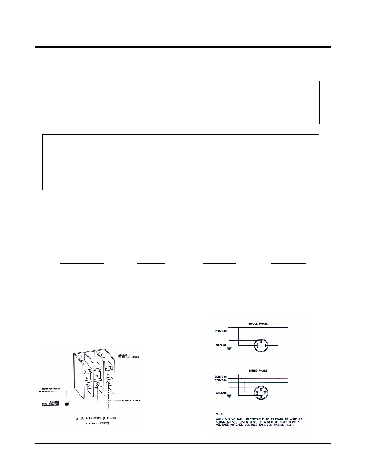
Power Supply Connection
ELECTRICAL SPECIFICATIONS
4 of 24

INSTALLATION INSTRUCTIONS
A. Qualified Personnel
These installation instructions are for the use of
qualified installation and service personnel only.
Installation or service by other than qualified
personnel may result in damage to the oven
and/or injury to the operator.
Qualified installation personnel are those individuals, firms,
companies or corporations which either in person or
through an agent are engaged in and responsible for:
• The installation of electrical wiring from the
electric meter, main control box or service
outlet to the electrical appliance. Qualified
installation personnel must be familiar with all
precautions required and have complied with all
requirements of state and local authorities
having jurisdiction. See: National Electrical
code, ANSI/NFPA 70-1990.
B. Delivery and Inspection
Duke Manufacturing Co., does everything within its power
to insure you receive your oven in good condition. They
are strapped down on heavy wooden skids and surrounded
by heavy "tri-wall" cartons to prevent shipping damage.
They have all been carefully inspected before they were
packaged and consigned to the carrier.
Upon Delivery of your Duke oven:
C. Location of the Oven
Proper planning and placement of the oven will give you
the best results in terms of long term user convenience and
satisfactory performance. We urge you to give adequate
thought in the placement of your oven prior to its arrival.
• The oven should be placed in an area which is
free from drafts and accessible for proper
operation and servicing.
• The area around the oven must be kept clear of
combustible materials. A minimum of one (1)
inch from the left or right side, three (3) inches
from the rear and eight (8) inches from the floor
must be maintained between the oven and any
combustible or non-combustible surface.
It is also important not to obstruct the natural flow of
ventilation air if the oven is to operate properly. Do
not place any objects on top of the oven. This oven
should not be installed on a curb base or sealed to the
wall. Either condition can prevent proper ventilation
of the blower motor. The blower motor has a thermal
protection device which will trip because of excessive
ambient temperatures at the side of the oven. If the
device trips continually, this condition should be
corrected immediately to avoid damaging the oven
permanently.
Before making any connections to the over, check the rating
plate to be sure the oven specifications concur with the
voltage and phase to be supplied to the oven.
• Look over the shipping container carefully
noting any exterior damage on the delivery
receipt which must also be signed by the
driver/delivery person.
• Uncrate and check for any damage which was
not evident on the outside of the shipping
container. This is called concealed damage.
The carrier must be notified within fifteen (15)
days of the delivery of the oven and the carton,
skid and all packaging materials must be
retained for inspection.
Duke Manufacturing Co. cannot assume liability for loss or
damage suffered in transit. The carrier assumes full
responsibility for delivery in good order
when the shipment was accepted. However, we are
prepared to assist you in filing any freight claim.
The rating plate and serial number data are located behind
the motor access cover on the right side panel.
D. Electrical Connections
Each section of the Duke 5/9 Half-Size Convection Ovens
is rated at 8.0 KW.
Your oven is supplied for connection to a 208 or 240 volt,
1-phase or 3-phase grounded circuit. The
electric motor, indicator lights and control circuits are
powered internally and do not have a separate power
supply.
Before making any connections to these units, check the
rating plate to assure that the voltage and phase rating of the
oven is compatible with the electrical supply. When
installing, all ovens must be electrically grounded in
accordance with local codes or in the absence of local
codes, with the National Electrical Code, ANSI/NFPA 701990 (in Canada - CSA Std. C22.1).
5 of 24

Wiring diagrams are located on the inside of the motor
access panel, on the right side of the oven.
E. Ventilation
Proper ventilation is very important for the proper function
of your oven. A good ventilation system will allow the oven
to function properly as well as remove unwanted vapors.
Not venting the ovens properly can result in unsatisfactory
baking results as well as the possibility of damaging your
oven.
F. Oven Assembly
Before assembling and installing the oven, please check to
make sure that all necessary parts are present. In addition to
the oven itself, there will also be legs, feet or casters. (For
double sections, retaining clips, and miscellaneous
hardware.) Please check the interior of all oven sections for
the parts needed to assemble and install your oven(s).
Leg Attachment (in lieu of stand)
• Once the oven has been removed from the
carton, lay it on its left side (the side without the
controls).
• Hold the leg and align with the matching holes
in base and leg flange. Carefully start the 5/16
18 bolts, (avoid cross-threading), by turning
clockwise and tighten to the nearest full turn. A
total of (12) 15/16-18 X 3/4 bolts, flat washers
and lock washers are required to secure all legs.
• Once legs are secured, add two (2) storage
shelves between the four (4) legs. Secure these
by using the 1/4-20 X 3/4 self-threading
screws. After completion, carefully lift the oven
to an upright position.
To level the unit, raise or lower the adjustable feet as
required.
G. Adjustments Associated with Installation
Each oven section and all its components parts have been
tested thoroughly and inspected before your oven was
shipped from the factory. However, it is sometimes
necessary to further test or adjust the oven once it has been
installed. Such adjustments are the responsibility of the
Dealer or Installer. These types of adjustments are not
considered defects, rather a normal and routine part of the
proper installation of the equipment.
These adjustments include but are not limited to:
• adjustments and recalibration of the controller
• adjustment to the doors, leveling
• and tightening of fasteners.
No installation should be considered complete without
proper inspection and, if necessary, any adjustments by
qualified service or installation personnel.
6 of 24
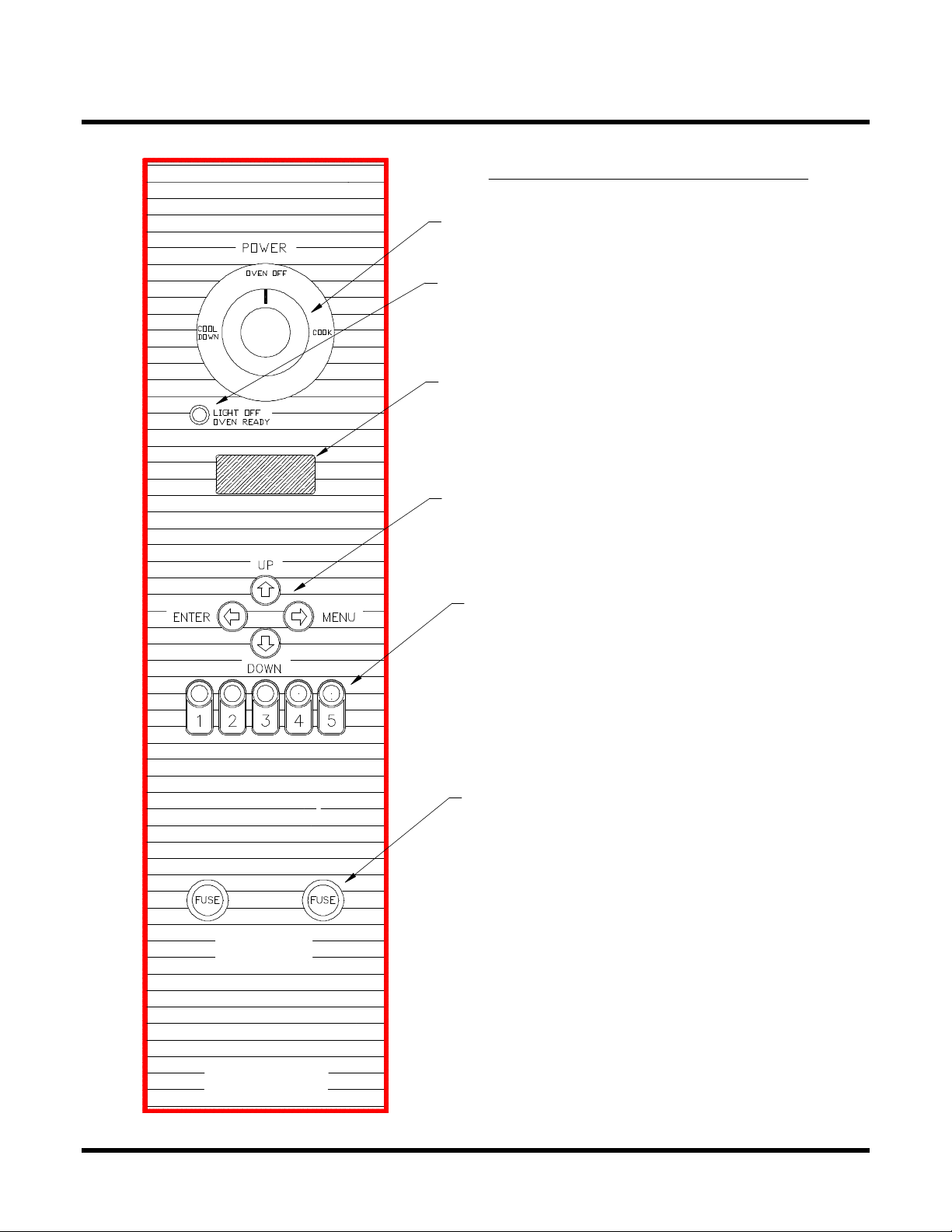
POPEYE'S OVEN CONTROLS
Main Power ON/OFF Switch
Power On Light - Indicates elements are
on. Light will go out when set temperature
has been reached.
Display - Indicates Time and/or Temperature
Programming Buttons
WARNING
REPLAC E WI TH 10 AMP
TIME DELAY FUSES
Preprogrammed Buttons - for
1 through 5 different recipe
settings.
Fuses - 10 Amp Time Delay Protective
FOR TE CHNICAL ASSISTANCE
OR SE RVICE, PLEASE CALL:
1-800-735- 3853
7 of 24
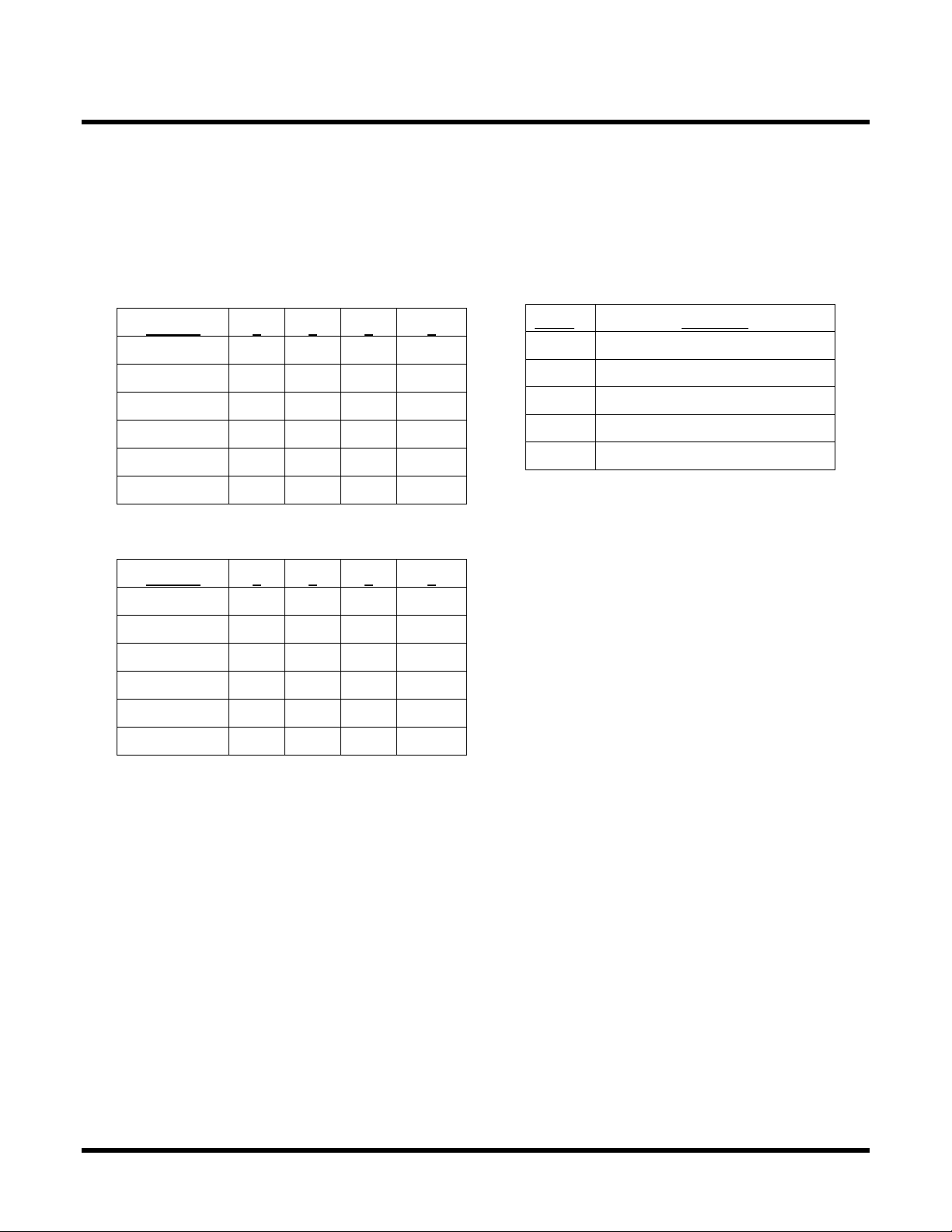
A. Program Parameters
This unit comes preprogrammed from the factory
with the following parameters for Menu items S1
and S2
Menu Item S1 (Use for Par Baked Biscuits)
# Trays 1 2 3 4
Cook Time 6:00 6:00 6:00 6:00
Temperature 375° 375° 375° 375°
On Time 60 80 130 160
Duty Cycle 160 160 160 160
Offset 0 0 0 0
Shelf Position 2 1,3 1,2,3 1,2,3,4
Menu Item S2 (Use for Fresh Biscuits)
# Trays 1 2 3 4
Cook Time 10:00 10:00 10:00 10:00
Temperature 375° 375° 375° 375°
On Time 80 100 130 160
Duty Cycle 160 160 160 160
Offset 0 0 0 0
Shelf Position 2 1,3 1,2,3 1,2,3,4
Shelf position is based on counting from the top rung
downward. (See oven drawing, page 9.)
For proper brownness, position each pan of biscuits in the
following manner.
B. Programming Instructions
Programming the Oven Control is simple. Anytime a
parameter (one of the five cooking times, one of the five
load control settings, duty cycle time-base, setpoint, or
offset) needs to be changed the procedure is:
• Select the desired menu item by holding down the
Gasket Groove
Push each pan all the way in until it hits the back
wall, then pull it forward (toward you) one (1)
inch.
MENU push button and pressing the UP/DOWN
buttons until the menu item is displayed (The Menu
items are numbered S1 through S7)
• Press both the number 1 and number 5
start switches at the same time. This
action tells the control that something is to be
changes; the alarm will sound, and the
number one (1) will appear in the display.
• Press one of the following buttons:
Switch To Change
1 Cooking Time
2 Cooking Temperature (Setpoint)
3 Duty Cycle On-Time
4 Duty Cycle Time Base
5 Offset
Switch 1 Pressed: The display will show the
number “2”. Press the switch that is to have its
baking time changed. The baking time for the
particular switch will be shown in the display. A
baking time must be programmed for selections 1,
2, 3 and 4. Use the UP/DowN buttons to change
the baking time to that desired.
NOTE: To change seconds hold in the start
switch for one tray, then use the UP/DOWN
switches.
Press the "Enter" switch to store the change.
Switch 2 Pressed: The setpoint temperature will
be shown in the display.
Use the Up/Down switch to set the new setpoint.
Press the "ENTER" switch to store the new
setpoint.
Switch 3 Pressed: The display will show the
number "2". Press the switch that is to have its
load control changed. The load control "ON
TIME" for that particular switch will be shown on
the display. An "On Time" must be programmed
for selections 1,2, 3 and 4.
Use the UP/DOWN switches to change the load
control setting.
Press the "ENTER" switch to store the new load
control setting.
Switch 4 Pressed: The Time Base will show in
the display.
8 of 24
 Loading...