

Duke 59-E3C User Manual
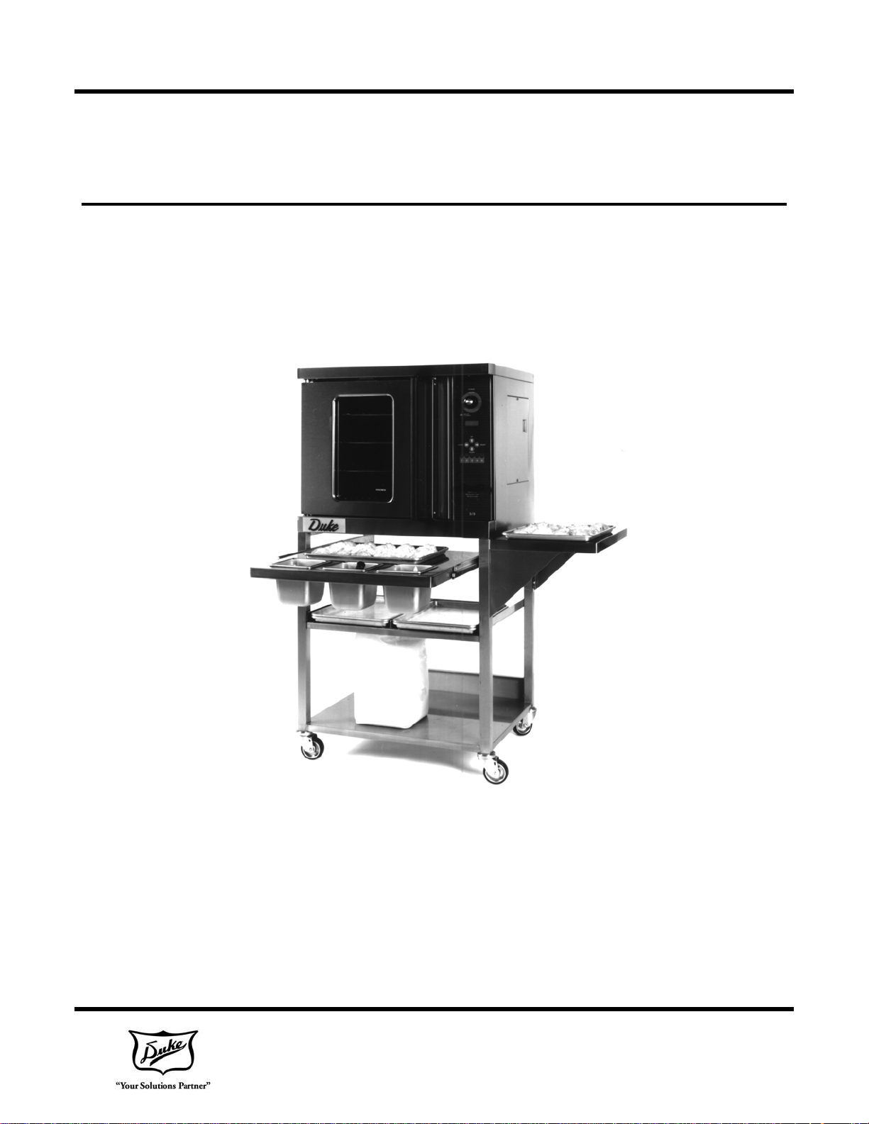
Duke 59-E3C
ELECTRIC HALF-SIZE
CONVECTION OVEN
Installation, Operation, Parts
& Maintenance Manual
DUKE MANUFACTURING CO.
2305 N. Broadway, St. Louis, MO 63102
800-735-3853 314-231-1130 314-231-5074 FAX:
www.dukemfg.com
REV Y 12/07/2017
PN 155409

This Page Intentionally Left Blank

INDEX
59-E3C Electrical Specifications 4
Installation Instructions
A. Qualified Personnel 5
B. Delivery & Inspection 5
C. Location of Oven 5
D. Ventilation 5
E. Electrical Connections 5
F. Oven Assembly 6
G. Installation 6
H. Adjustments Associated with Installation 6
Control Panel 7
A. Program Oven 8-13
B. Operation of Oven 13
C. Cool Down Operation 13
D. Emergency Back-Up System 14
E. Troubleshooting 14-15
F. Cleaning the Oven 15
Cleaning Instructions 16
Maintenance Instructions 17
A. Adjustments 17
B. Door Adjustments 17
C. Lubrication 17
D. Calibration Check 17
Repair Parts List and Corresponding Drawings 18 - 23
Wiring Diagram 24 - 26
Please supply the Model Number and the Serial Number when
ordering replacement parts or requesting service.
We recommend service by Duke Authorized Service
Agencies during and after the warranty period.
3 of 28
FOR YOUR SAFETY
Do not store gasoline or other flammable liquids in the vicinity of this appliance.
WARNING
Improper installation, adjustment, service or maintenance can cause property
damage, injury or death. Read all installation, operating and maintenance
instructions thoroughly before installing or servicing this appliance.
Model 59-E3C
ELECTRICAL SPECIFICATIONS
TOTAL KW VOLTS 1 PHASE 3 PHASE
8.0 208 41.0 AMPS 24.0 AMPS/PH
8.0 240 36.0 AMPS 21.0 AMPS/PH
Power Supply Connection
4 of 28

INSTALLATION INSTRUCTIONS
A. Qualified Personnel
These installation instructions are for the use of
qualified installation and service personnel only.
Installation or service by other than qualified service
personnel may result in damage to the oven and/or
injury to the operator.
Qualified installation personnel are those individuals,
firms, companies or corporations which either in
person or through an agent are engaged in and
responsible for:
The installation of electrical wiring from the
electric meter, main control box or service
outlet to the electrical appliance. Qualified
installation personnel must be familiar with
all precautions required and have complied
with all requirements of state and local
authorities having jurisdiction.
B. Delivery and Inspection
For transport, ovens are strapped down on wooden
skids and surrounded by "tri-wall" cartons to prevent
shipping damage. They have been carefully
inspected before they were packaged and
consigned to the carrier.
C. Location of the Oven
Proper planning and placement of the oven is
required for the proper function of the oven. Please
do consider the following requirements:
The oven should be placed in an area
which is free from drafts and accessible
for proper operation and servicing.
The area around the oven must be kept
clear of combustible materials. A minimum
of one (1) inch from the left or right side,
three (3) inches from the rear and eight (8)
inches from the floor must be maintained
between the oven and any combustible or
non-combustible surface.
D. Ventilation
It is important not to obstruct the cooling system flow
of the oven. Do not place any objects on top of the
oven. This oven should not be installed on a curb
base or sealed to the wall. Either condition can
prevent proper ventilation of the oven components.
The blower motor has a thermal protection device,
which will trip because of excessive ambient
temperatures at the side of the oven. If the device
trips continually, this condition should be corrected
immediately to avoid damaging the oven
permanently.
Upon Delivery of your Duke oven:
Look over the shipping container carefully
noting any exterior damage on the
delivery receipt.
Uncrate and check for any damage which
was not evident on the outside of the
shipping container. The carrier must be
notified within fifteen (15) days of the
delivery of the oven and the carton, skid
and all packaging materials must be
retained for inspection.
Duke Manufacturing Co. cannot assume liability for
loss or damage suffered in transit. The carrier
assumes full responsibility for the delivery in good
order when the shipment was accepted. If you need
assistance in preparing a freight claim call Duke
Manufacturing Co.
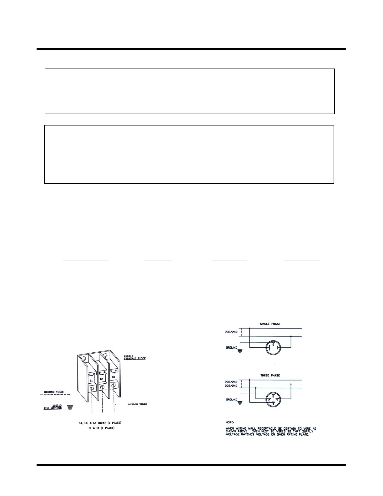
E. Electrical Connections
Verify the rating plate to be sure the oven
specifications concur with the voltage and phase to
be supplied to the oven. The rating plate and serial
number data are located behind the motor access
cover on the right side panel.
The following installation steps should only be
conducted by authorized service personnel or a
qualified electrician.
Your oven is supplied for connection to a 208 or 240
volt, 1-phase or 3-phase grounded circuit.
Before making any connections to these units, check
the rating plate to assure that the voltage and phase
rating of the oven is compatible with the electrical
supply. All ovens must be electrically grounded in
accordance with local codes. In the absence of local
codes, the National Electrical Code, ANSI/NFPA 701990 (in Canada - CSA Std. C22.1) applies.
5 of 28

Wiring diagrams are located on the inside of the
motor access panel, on the right side of the oven.
F. Oven Assembly
Before assembling and installing the oven, please
check to make sure that all necessary parts are
present. The contents of the package should contain
a detailed packaging list. Depending on the specified
equipment, the shipped package also should
contain:
- Mounting equipment (legs, casters, feet)
- Rack frame and oven racks (in the cavity)
G. Installation
The following installation steps should only be
conducted by authorized service personnel.
Leg Attachment (in lieu of stand)
Once the oven has been removed from
the carton, lay it on its left side (the side
without the controls).
are the responsibility of the Dealer or Installer.
These types of adjustments are not considered
defects, rather a normal and routine part of the
proper installation of the equipment.
These adjustments include but are not limited to:
adjustments and recalibration of the
controller
adjustment to the doors, leveling
and tightening of fasteners.
No installation should be considered complete
without proper inspection and, if necessary, any
adjustments by qualified service or installation
personnel.
Hold the leg and align with the matching
holes in base and leg flange. Carefully
start the 5/16 18 bolts, (avoid crossthreading), by turning clockwise and
tighten to the nearest full turn. A total of
(12) 15/16-18 X 3/4 bolts, flat washers
and lock washers are required to secure
all legs.
Once legs are secured, add two (2)
storage shelves between the four (4) legs.
Secure these by using the 1/4-20 X 3/4
self-threading screws. After completion,
carefully lift the oven to an upright
position.
To level the unit, raise or lower the adjustable feet
as required.
H. Adjustments Associated with
Installation
Each oven section and all its components parts have
been tested thoroughly and inspected before your
oven was shipped from the factory. However, it is
sometimes necessary to further test or adjust the
oven once it has been installed. Such adjustments
6 of 28
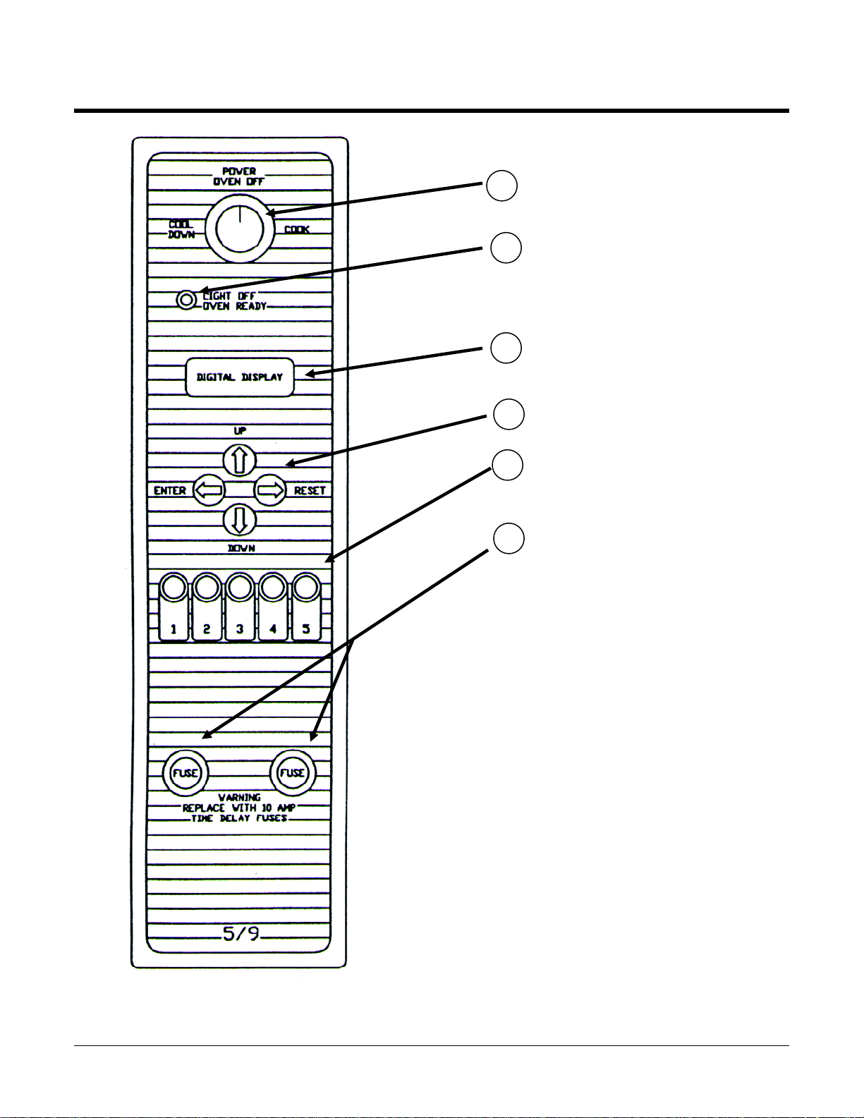
Oven Controls
Main Power ON/OFF Switch
1
2
Power On Light -Indicates elements
are on. Light will go out when set
temperatures has been reached.
3
Indicates Time and/or Temperature
4
UP/DOWN Programming Keys
5
Preprogrammed buttons for 1
through 5 different recipe settings.
10 Amp Time Delay Protective Fuses
6
7 of 28
A. Programming Oven
PROGRAMMING DUKE OVENS
For additional information on Duke Ovens including authorized service representatives and
replacement Operation Manual call (800) 735-3853 or www.dukemfg.com
OVEN RACK POSITIONING
To help ensure proper baking, oven racks should be on the 3rd, 6th, and 9th rungs (counting from the
bottom rack first).
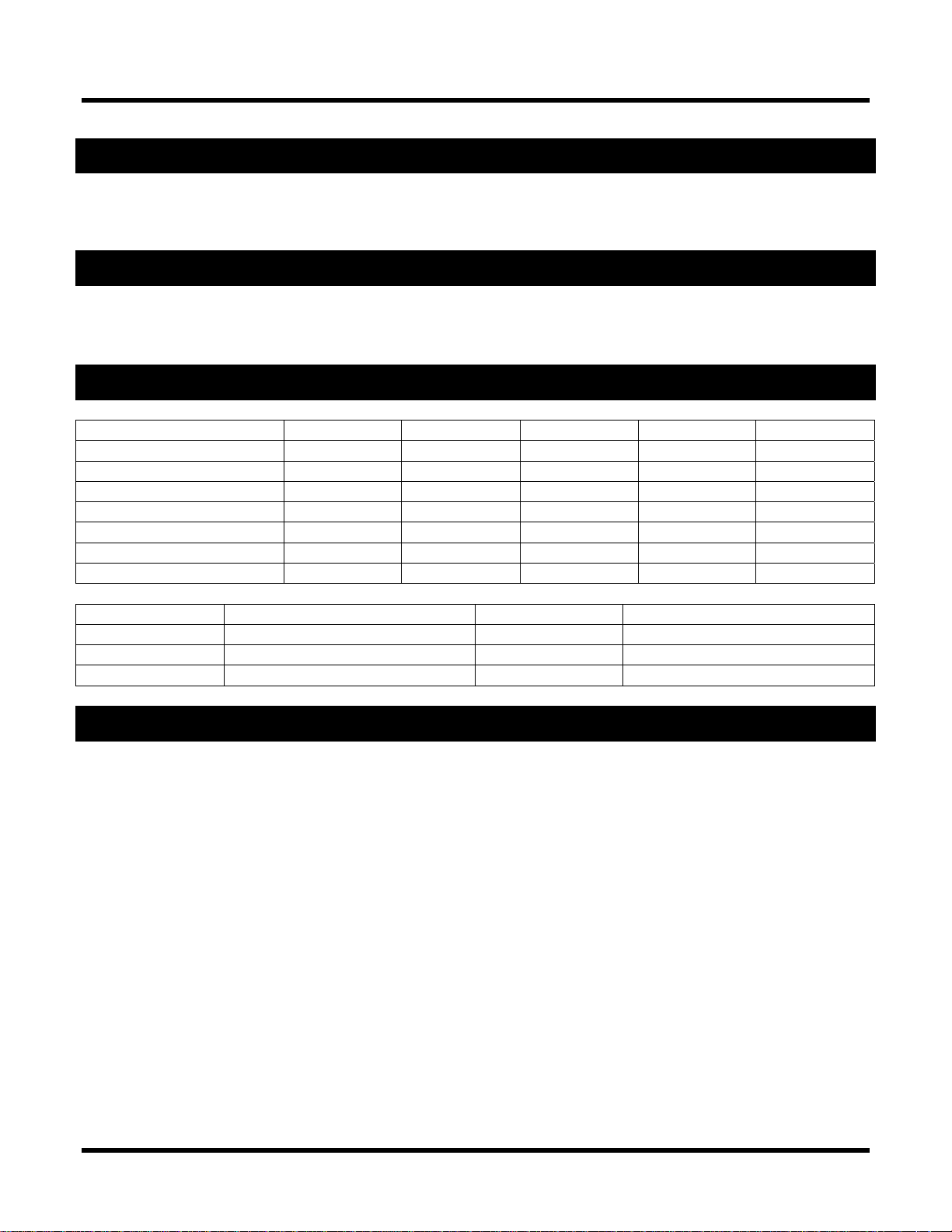
PROGRAMMING PARAMETERS
Button 1 Button 2 Button 3 Button 4 Button 5
# of Trays / Product 1 2 3 Mac & Chz 1 Mac & Chz 2
Cook Time 10:00 11:30 11:30 9:00 11:00
Temperature 375° 375° 375° 375° 375°
On Time 60 85 100 60 85
Duty Cycle 160 160 160 160 160
Offset 30 30 30 30 30
Shelf Position 6 6 & 9 3, 6 & 9 6 3 & 6
Timer Button # Use Timer Button # Use
1 One pan of biscuits 2 Two pans of biscuits
3 Three pans of biscuits 4 One pan of Mac & Cheese
5 Two pans of Mac & Cheese
COOK TIME SETTING PROCECDURES BUTTON 1 – 10:00 MINUTES
Step 1 (Change Time)
Press number 1 and number 5 buttons at the same time (Display will show 1)
Step 2
Press button #1 (Display will show 2)
Step 3
Press button #1 (Display will show current bake time)
Step 4
Use up/down arrows to change baking time to desired time (10:00)
Note: To change seconds in some models, hold in the start (#1) button then use Up / Down
Arrows to change seconds
Step 5
Press enter button to store change
Now test timer button number 1 to make sure it times for 10:00 minutes
8 of 28

COOK TIME SETTING PROCECDURES BUTTON 2 & BUTTON 3 – 11:30 MINUTES
Step 1 (Change Time)
Press number 1 and number 5 buttons at the same time (Display will show 1)
Step 2
Press button #1 (Display will show 2)
Step 3
Press button #2 (Display will show current bake time)
Step 4
Use up/down arrows to change baking time to desired time (11:30)
Note: To change seconds in some models, hold in the start (#2) button then use Up / Down
Arrows to change seconds
Step 5
Press enter button to store change
Step 6 (Change Time)
Press number 1 and number 5 buttons at the same time (Display will show 1)
Step 7
Press button #1 (Display will show 2)
Step 8
Press button #3 (Display will show current bake time)
Step 9
Use up/down arrows to change baking time to desired time (11:30)
Note: To change seconds in some models, hold in the start (#2 or #3) button then use Up /
Down Arrows to change seconds
Step 10
Press enter button to store change
Now test timer button number 2 and 3 to make sure it times for 11:30 minutes
COOK TIME SETTING PROCECDURES BUTTON 4 – 9:00 MINUTES (MAC & CHEESE)
Step 1 (Change Time)
Press number 1 and number 5 buttons at the same time (Display will show 1)
Step 2
Press button #1 (Display will show 2)
Step 3
Press button #4 (Display will show current bake time)
Step 4
Use up/down arrows to change baking time to desired time (9:00)
Note: To change seconds in some models, hold in the start (#4) button then use Up / Down
Arrows to change seconds
Step 5
Press enter button to store change
Now test timer button number 4 to make sure it times for 9:00 minutes
9 of 28
 Loading...