

Duke 59-BS Service Manual
ELECTRIC
CONVECTION OVEN
MODELS
5/9 THE OVEN
5/9 SERIES OVENS
6/13 THE OVEN
E SERIES
59-E3C
59-E3P
SERVICE MANUAL
Please read this manual completely before attempting to
install, operate or service this equipment
This manual is Copyright © 2011 Duke Manufacturing Co. All rights reserved.
Reproduction without written permission is prohibited. Duke is a registered
trademark of the Duke Manufacturing Co.
Duke Manufacturing Co.
2305 N. Broadway
St. Louis, MO 63102
Phone: 314-231-1130
Toll Free: 1-800-735-3853
Fax: 314-231-5074
www.dukemfg.com
P/N 153611B
Service Manual for Electric Convection Oven
IMPORTANT WARNING AND SAFETY INFORMATION
WARNING
READ THIS MANUAL THOROUGHLY BEFORE OPERATING, INSTALLING OR
PERFORMING MAINTENANCE ON THE EQUIPMENT.
WARNING
FAILURE TO FOLLOW INSTRUCTIONS IN THIS MANUAL CAN CAUSE PROPERTY
DAMAGE, INJURY OR DEATH.
WARNING
DO NOT USE OR STORE GASOLINE OR OTHER FLAMMABLE VAPORS OR LIQUIDS IN
THE VICINITY OF THIS OR ANY OTHER APPLIANCE.
WARNING
DO NOT OPERATE THIS EQUIPMENT WITHOUT PROPERLY PLACING AND SECURING
ALL COVER AND ACCESS PANELS.
CAUTION
Observe the following:
• Provide and maintain adequate minimum clearances from all walls and combustible materials.
• Provide and maintain adequate clearance for air openings.
• Keep the equipment area free and clear of combustible material.
• Operate equipment only on the type of electricity indicated on the specication plate.
• Retain this manual for future reference.
2

Service Manual for Electric Convection Oven
TABLE OF CONTENTS
INTRODUCTION ..................................................................................................................................................................6
GENERAL .....................................................................................................................................................................6
INSTALLATION .............................................................................................................................................................6
OPERATION .................................................................................................................................................................6
CLEANING ....................................................................................................................................................................6
TOOLS ..........................................................................................................................................................................6
Standard.................................................................................................................................................................6
ELECTRICAL SPECIFICATIONS ..................................................................................................................................6
COMPONENT REMOVAL AND REPLACEMENT ................................................................................................................7
Electrical LOCKOUT/TAGOUT Procedure ....................................................................................................................7
RIGHT SIDE PANEL (OVENS WITH DUAL DOORS) ...................................................................................................7
X CONTROL PANEL ASSEMBLY .................................................................................................................................8
Component Access Procedure...............................................................................................................................8
POWER Switch ......................................................................................................................................................8
X Controller ............................................................................................................................................................8
OVEN READY Light ...............................................................................................................................................8
Fan Switch .............................................................................................................................................................8
Fuse and Fuse Holder ...........................................................................................................................................8
LIGHT Switch .........................................................................................................................................................8
XX CONTROL PANEL ASSEMBLY ...............................................................................................................................9
Component Access Procedure...............................................................................................................................9
POWER Switch ......................................................................................................................................................9
XX Controller ..........................................................................................................................................................9
OVEN READY Light ...............................................................................................................................................9
Fan Switch .............................................................................................................................................................9
LIGHT Switch .........................................................................................................................................................9
Fuse and Fuse Holder ...........................................................................................................................................9
Z CONTROL PANEL ASSEMBLY .............................................................................................................................. 10
Component Access Procedure............................................................................................................................ 10
POWER Switch ................................................................................................................................................... 10
Z Controller ......................................................................................................................................................... 10
OVEN READY Light ............................................................................................................................................ 10
Fuse and Fuse Holder Light ................................................................................................................................ 10
LIGHT Switch ...................................................................................................................................................... 10
ZX CONTROL PANEL ASSEMBLY .............................................................................................................................11
Component Access Procedure.............................................................................................................................11
POWER Switch ....................................................................................................................................................11
ZX Controller ........................................................................................................................................................11
OVEN READY Light .............................................................................................................................................11
LIGHT Switch .......................................................................................................................................................11
Fuse and Fuse Holder Light .................................................................................................................................11
ZZ CONTROL PANEL ASSEMBLY ............................................................................................................................ 12
Component Access Procedure............................................................................................................................ 12
POWER Switch ................................................................................................................................................... 12
ZZ Oven Control.................................................................................................................................................. 12
Fuse and Fuse Holder Light ................................................................................................................................ 12
6/13 & 5/9 V CONTROLLER ASSEMBLY & “E”SERIES-ELECTRO MECHANICAL CONTROLLER ASSEMBLY... 13
Component Access Procedure............................................................................................................................ 13
POWER Switch ................................................................................................................................................... 13
TEMPERATURE Control ..................................................................................................................................... 13
1 - Hour TIMER ................................................................................................................................................... 13
OVEN READY Light ............................................................................................................................................ 13
3

Service Manual for Electric Convection Oven
Fan Switch .......................................................................................................................................................... 13
LIGHT Switch ...................................................................................................................................................... 13
Fuse and Fuse Holder Light ................................................................................................................................ 13
Buzzer ................................................................................................................................................................. 13
59-E3P OVEN CONTROLS ....................................................................................................................................... 14
Component Access Procedure............................................................................................................................ 14
POWER Switch ................................................................................................................................................... 14
Controller............................................................................................................................................................. 14
OVEN READY Light ............................................................................................................................................ 14
Fuse and Fuse Holder Light ................................................................................................................................ 14
Transformer ......................................................................................................................................................... 14
Contactor............................................................................................................................................................. 14
Terminal Block ..................................................................................................................................................... 14
CONTROL CIRCUIT BOARD REPLACEMENT ......................................................................................................... 15
CONTROL CIRCUIT BOARD JUMPER SETTINGS .................................................................................................. 15
Single Menu Jumper Setting (Churches or Popeye’s) ........................................................................................ 15
Seven Menu Jumper Settings (Popeye’s Chicken only) ..................................................................................... 16
MOTOR ...................................................................................................................................................................... 16
Side Mounted Motor ............................................................................................................................................ 16
Rear Mounted Motor ........................................................................................................................................... 17
STEP-DOWN TRANSFORMER ................................................................................................................................. 18
POWER TRANSFORMER ......................................................................................................................................... 18
3-RELAY PRINTED CIRCUIT BOARD (Relay Board) ............................................................................................... 18
RTD PROBE .............................................................................................................................................................. 19
THERMOSTAT ........................................................................................................................................................... 19
KX THERMOSTAT ..................................................................................................................................................... 20
BACKUP TOGGLE SWITCH...................................................................................................................................... 20
ELEMENTS ................................................................................................................................................................ 21
Side Mounted Elements ...................................................................................................................................... 21
Back Mounted Elements ..................................................................................................................................... 22
OVEN LIGHTS ........................................................................................................................................................... 23
DOORS ...................................................................................................................................................................... 23
Removal .............................................................................................................................................................. 23
Disassembly ........................................................................................................................................................ 23
Gasket Replacement........................................................................................................................................... 23
Roller Latch ......................................................................................................................................................... 24
Door Switch ......................................................................................................................................................... 24
Door Handle ........................................................................................................................................................ 24
Turnbuckle Assembly (2-door 6/13 Series only) ................................................................................................ 24
SERVICE PROCEDURES ................................................................................................................................................ 25
MAINTENANCE INSTRUCTIONS ............................................................................................................................. 25
Oven Door Adjustment ........................................................................................................................................ 25
6/13 Series Turnbuckle Adjustment..................................................................................................................... 25
Oven Door Switch Adjustment ............................................................................................................................ 25
OVEN DOOR SWITCH CHECK ................................................................................................................................. 26
THERMOSTAT CALIBRATION .................................................................................................................................. 26
Check Calibration ................................................................................................................................................ 26
To Calibrate the Thermostat ................................................................................................................................ 26
ELEMENT .................................................................................................................................................................. 27
RTD ............................................................................................................................................................................ 27
MOTOR CIRCUIT CHECK ......................................................................................................................................... 27
4

Service Manual for Electric Convection Oven
ZZ CONTROLLER PROGRAMMING ........................................................................................................................ 28
System Programming .......................................................................................................................................... 28
Factory Programming .......................................................................................................................................... 29
TROUBLESHOOTING CHARTS ....................................................................................................................................... 30
6/13 V CONTROLLER AND E SERIES ELECTRO-MECHANICAL CONTROLLER ................................................. 30
5/9 OVEN WITH ZZ CONTROLLER .......................................................................................................................... 31
ALL SOLID STATE CONTROLLERS EXCEPT ZZ CONTROLLER .......................................................................... 32
5/9 CCSI CONTROL WITH BACKUP THERMOSTAT ............................................................................................... 33
SCHEMATIC DIAGRAMS
5/9 “V” OPTION 208/240 VAC. 50/60 HZ 1PH OR 3PH .................................................................................................... 34
6/13 “V” OPTION 208/240 VAC. 50/60 HZ 1PH OR 3PH .................................................................................................. 35
6/13 “V” OPTION PULSE PLUS 208/240 VAC. 50/60 HZ 1PH OR 3PH .......................................................................... 36
6/13 “V” OPTION 480 VAC. 50/60 HZ 1PH OR 3PH ......................................................................................................... 37
6/13 “V” OPTION PULSE PLUS 440/480 VAC. 50/60 HZ 1PH OR 3PH .......................................................................... 38
5/9 “X” OPTION 208/240 VAC. 50/60 HZ 1PH OR 3PH .................................................................................................... 39
6/13 “X” PULSE OPTION 208/240 VAC. 50/60 HZ 1PH OR 3PH ..................................................................................... 40
6/13 “X” PULSE OPTION 208/240 VAC. 50/60 HZ 1PH OR 3PH .................................................................................... 41
6/13 “X” PULSE PLUS OPTION 208/240 VAC. 50/60 HZ 1PH OR 3PH .......................................................................... 42
S 6/13 “X” OPTION 440/480 VAC. 50/60 HZ 1PH OR 3PH .............................................................................................. 43
6/13 “X” PULSE OPTION 440/480 VAC. 50/60 HZ 1PH OR 3PH ..................................................................................... 44
6/13 “X” PULSE PLUS OPTION 440/480 VAC. 50/60 HZ 1PH OR 3PH .......................................................................... 45
5/9 “Z & ZX” OPTION 208/240 VAC. 50/60 HZ 1PH OR 3PH ........................................................................................... 46
6/13 “Z, ZX” OPTION 208/240 VAC. 50/60 HZ 1PH OR 3PH ........................................................................................... 47
6/13 “Z, ZX” OPTION 480 VAC. 50/60 HZ 1PH OR 3PH .................................................................................................. 48
6/13 “ZZ” OPTION 208/240 VAC. 50/60 HZ 1PH OR 3PH ................................................................................................ 49
5/9 & 6/13 “ZZ” OPTION 208/240 VAC. 50/60 HZ 1PH OR 3PH ...................................................................................... 50
5/9 “ZZ” OPTION 208/240 VAC. 50/60 HZ 1PH OR 3PH .................................................................................................. 51
5/9 THERMOSTAT 208/240 VAC. 50/60 HZ 1PH OR 3PH ............................................................................................... 52
WIRING DIAGRAMS
5/9 “V” 208/240 V .............................................................................................................................................................. 53
6/13 “V” 208/240 V ............................................................................................................................................................ 54
6/13 “V” OPTION 208/220 OR 230/240 VAC. 1PH OR 3PH ............................................................................................. 55
6/13 “V” PULSE PLUS 208/240 V ..................................................................................................................................... 56
6/13 “V” 440/480 V ............................................................................................................................................................ 57
6/13 “V” PULSE 440/480 V................................................................................................................................................ 58
6/13 “X” 208/240 V ............................................................................................................................................................ 59
6/13 “X” PULSE PLUS 208/240 V ..................................................................................................................................... 60
5/9 “X” COM6000 208/240 V ............................................................................................................................................. 61
6/13 “X” 440/480 V ............................................................................................................................................................ 62
6/13 “X” PULSE 440/480 V................................................................................................................................................ 63
6/13 “X” PULSE PLUS 440/480 V ..................................................................................................................................... 64
6/13 “X” PULSE PLUS 440/480 V ..................................................................................................................................... 65
6/13 “W” OPTION COM6000 208/240 VAC. 1PH OR 3PH ............................................................................................... 66
6/13 “Z” “ZX” 208/240 V..................................................................................................................................................... 67
5/9 “Z” “ZX” 208/240 V....................................................................................................................................................... 68
6/13 “Z” “ZX” 440/480 V..................................................................................................................................................... 69
6/13 “ZZ” W/BACKUP 208/240 V ...................................................................................................................................... 70
5/9 “ZZ” W/BACKUP 208/240 V ........................................................................................................................................ 71
5/9 CCSI BACKUP TSTAT 208/240 V ............................................................................................................................... 72
CUSTOMER ASSISTANCE ............................................................................................................................................... 75
5
Service Manual for Electric Convection Oven
INTRODUCTION
GENERAL
Illustrations used in this manual may show any model
unless the information is specic to a particular model.
All procedures are applicable to all models unless
specically indicated.
INSTALLATION
For detailed installation instructions, refer to the
Installation and Operation Manual.
OPERATION
For specific operating instructions, refer to the
Installation and Operation Manual.
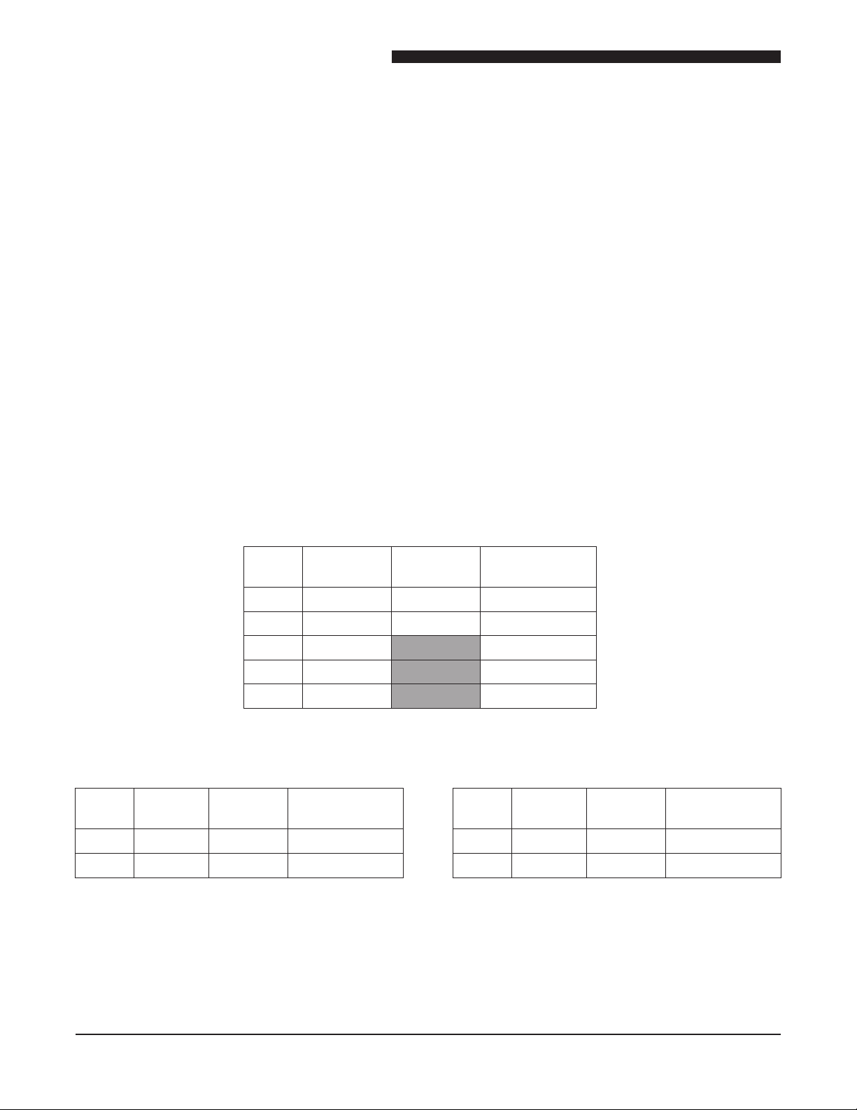
ELECTRICAL SPECIFICATIONS
6/13 and “E” CONVECTION OVEN
TOTAL
KW
VOLTS 1 PHASE 3 PHASE
CLEANING
For specic cleaning instructions, refer to the Installation
and Operation Manual.
TOOLS
Standard
• Standard set of hand tools.
• VOM with A.C. current tester (Any quality VOM
with a sensitivity of at lease 20,000 ohms per volt
can be used).
• Pyrometer
10 208 53 Amps 31 amps
10 240 46 Amps 27 amps
10 220/380 20 amps
10 240/415 18 amps
10 480 14 amps
5/9 THE OVEN
TOTAL
KW
10 208 53 Amps 31 amps
10 240 46 Amps 27 amps
VOLTS 1 PHASE 3 PHASE
5/9, 59-E3C, 59-53P OVENS
TOTAL
KW
8 208 41 Amps 24 amps
8 240 36 Amps 21 amps
VOLTS 1 PHASE 3 PHASE
6
Service Manual for Electric Convection Oven
5
/
9
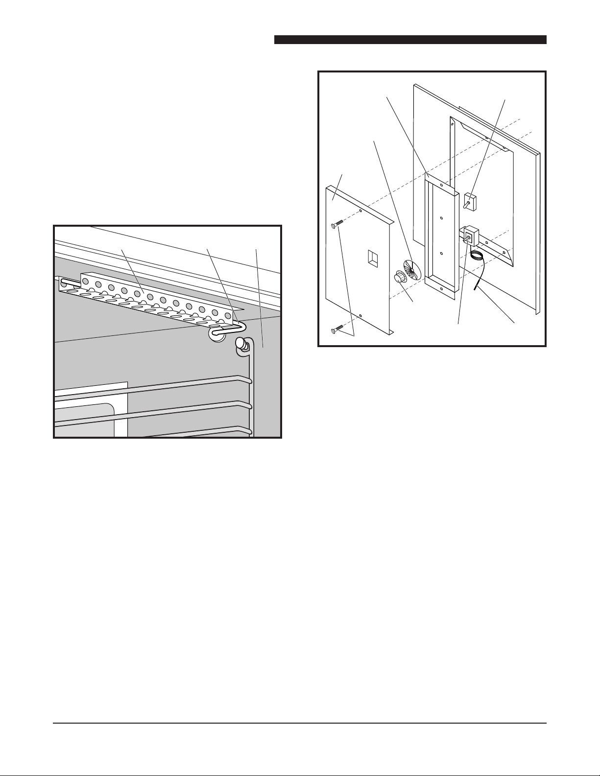
WARNING
Screw
Control
Panel
Lower
Trim
Piece
Insert
Panel
Right
Side
Panel
COMPONENT REMOVAL AND REPLACEMENT
Electrical LOCKOUT/TAGOUT
Procedure
WARNING: BEFORE PERFORMING ANY
SERVICE THAT INVOLVES
ELECTRICAL CONNECTION
OR DISCONNECTION AND/OR
EXPOSURE TO ELECTRICAL
COMPONENTS, ALWAYS
FOLLOW THE ELECTRICAL
LOCKOUT/TAGOUT PROCEDURE.
DISCONNECT ALL CIRCUITS.
FAILURE TO COMPLY CAN CAUSE
PROPERTY DAMAGE, INJURY OR
DEATH.
The Electrical LOCKOUT/TAGOUT Procedure is used
to protect personnel working on an electrical appliance.
Before performing any maintenance or service that
requires exposure to electrical components, follow
these steps:
1. In electrical box, place appliance circuit breaker
into OFF position.
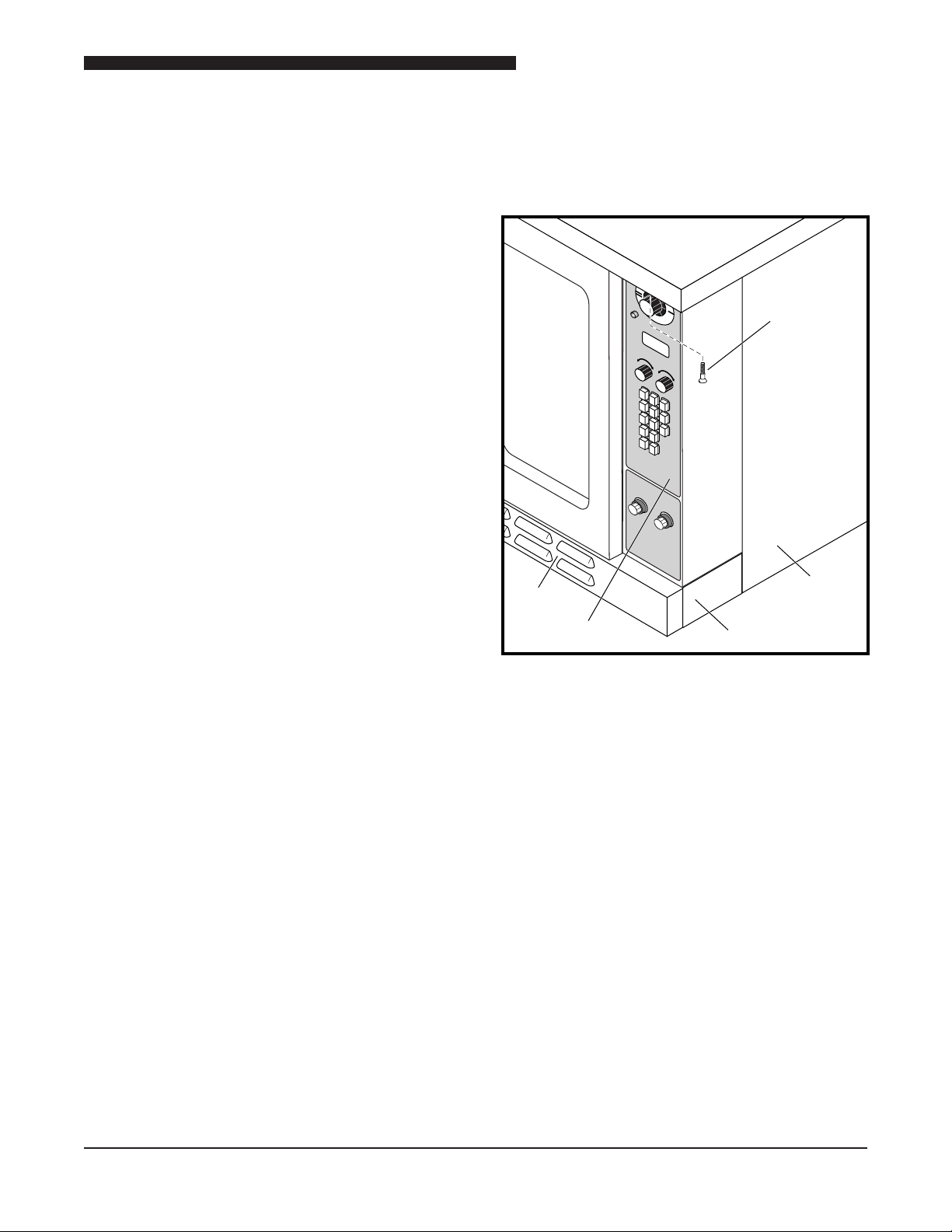
RIGHT SIDE PANEL
(OVENS WITH DUAL DOORS)
2. Place a lock or other device on electrical box
cover to prevent someone from placing circuit
breaker ON.
3. Place a tag on electrical box cover to indicate that
appliance has been disconnected for service and
power should not be restored until tag is removed
by maintenance personnel.
4. Disconnect appliance power cord from electrical
outlet.
5. Place a tag on the cord to indicate that unit
has been disconnected for service and power
should not be restored until tag is removed by
maintenance personnel.
1. Remove the screw at the top of the Control Panel.
2. Rotate the panel down about 90° being careful not
to damage wiring, RTD or Thermocouple tube.
3. Loosen the four screws that hold the front lower
Trim Panel in place.
4. Slide the Trim Panel forward, and remove it.
Before the large side panel can be removed the
stainless steel insert panel behind the control
compartment must rst be removed.
5. Remove the two screws that hold the small stainless
steel insert panel in place.
6. Slide the panel forward and out of the oven.
7. To remove the large side panel remove the six
screws on the front and rear anges of the panel.
8. Pull the panel free from bottom and remove it.
7
Service Manual for Electric Convection Oven
5
/
9
WARNING
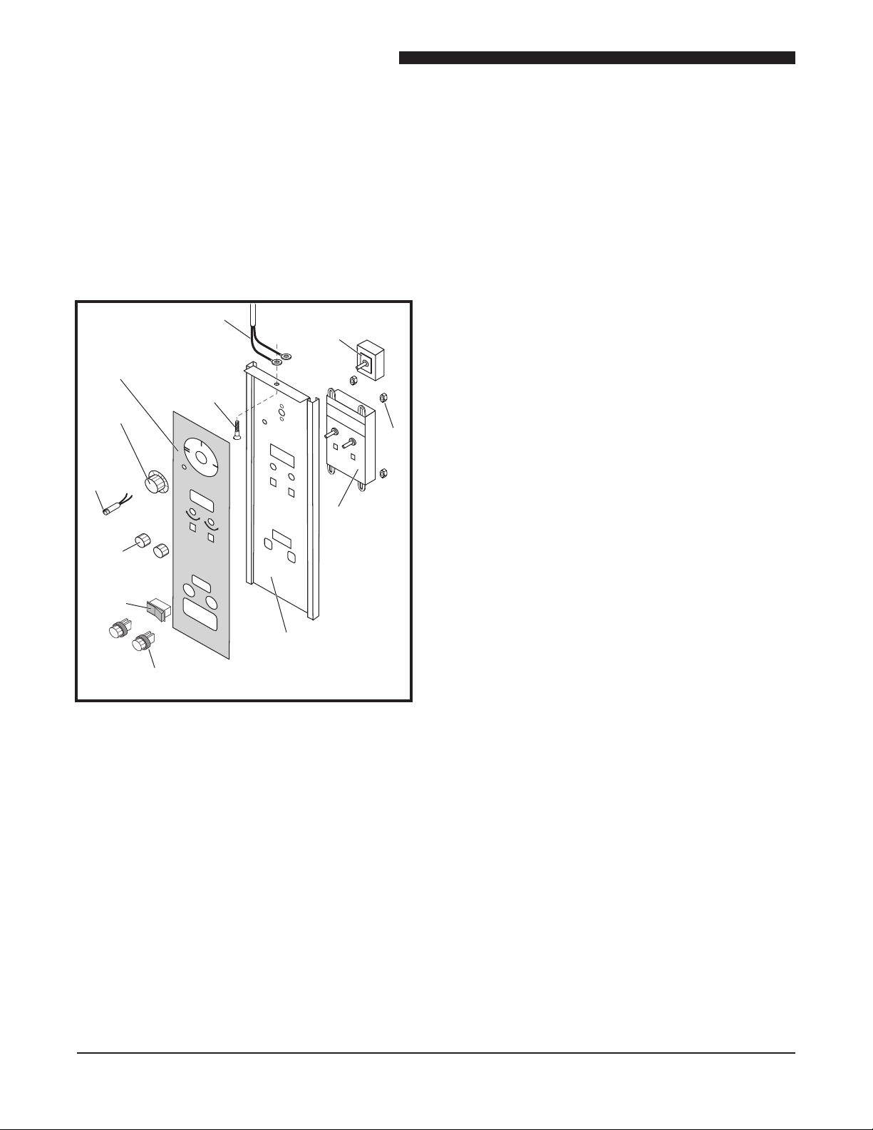
Power
Switch
Nut
X Controller
Temperature
Probe
Screw
Knob
Oven
Ready
Light
Knob
Fan
Switch
Fuse Holder &
Fuse (10 amp delay)
Control
Panel
Mylar
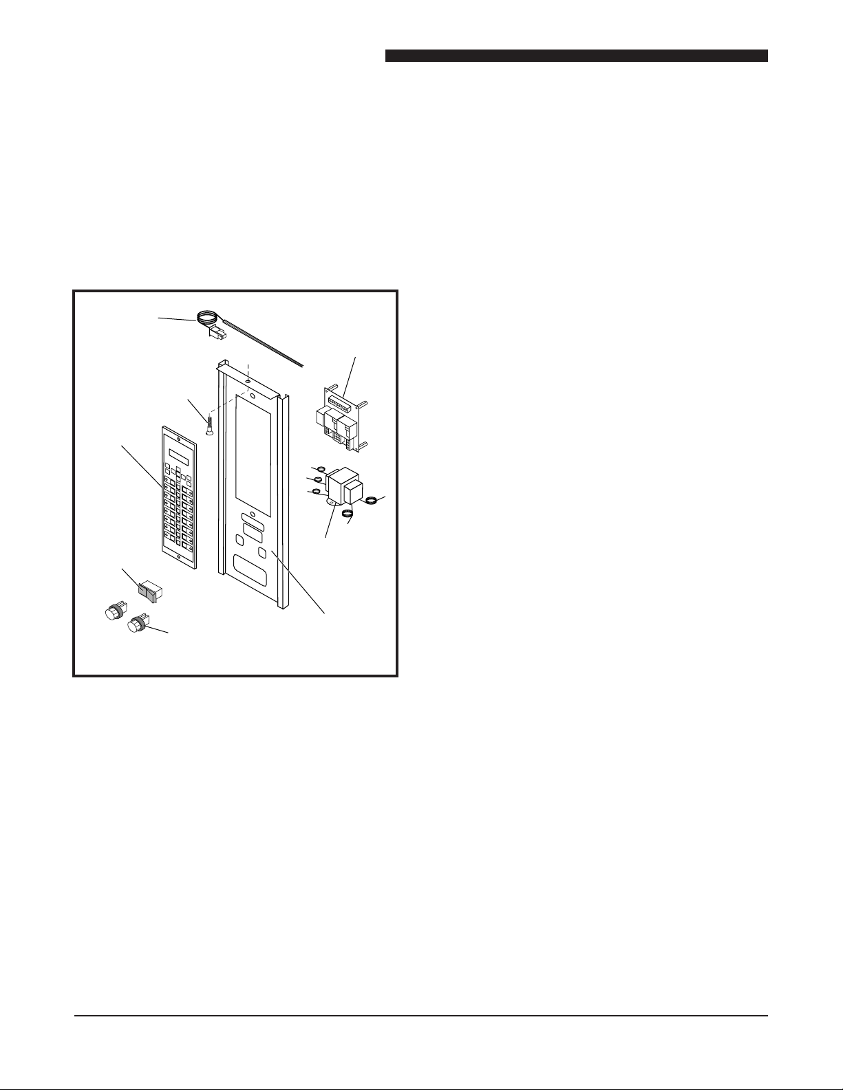
X CONTROL PANEL ASSEMBLY
WARNING: DISCONNECT OVEN FROM POWER
SOURCE BEFORE PERFORMING
ANY SERVICE.
Component Access Procedure
Remove screw at top center of X Control Panel assembly
and slide Control Panel out to allow access to Control
Panel components.
X Controller
1. Perform Component Access Procedure.
2. Tag and disconnect wires from Controller.
3. Remove knobs from front of Control Panel.
4. Remove four nuts securing Controller to Control
Panel.
5. Remove Controller from rear of Control Panel.
6. Reverse procedure to install a new Controller.
OVEN READY Light
1. Perform Component Access Procedure.
2. Tag and disconnect wires to OVEN READY Light.
3. Remove OVEN READY Light from front of Control
Panel.
4. Reverse procedure to install a new OVEN READY
Light.
Fan Switch
POWER Switch
1. Perform Component Access Procedure.
2. Loosen setscrews and remove knob from POWER
Switch.
3. Tag and disconnect wires from POWER Switch.
4. Remove nut securing POWER Switch.
5. Remove POWER Switch from rear of panel.
6. Reverse procedure to install POWER Switch.
1. Perform Component Access Procedure.
2. Tag and disconnect wires from Fan Switch.
3. Remove Fan Switch from front of Control Panel.
4. Reverse procedure to install a new Fan Switch.
Fuse and Fuse Holder
1. Perform Component Access Procedure.
2. Remove screw (1) to access back of Control Panel
to replace Fuse Holder.
3. Tag and disconnect wires to Fuse Holder.
4. Remove nut securing Fuse Holder.
5. Remove Fuse Holder from front of Control Panel.
6. Reverse procedure to install Fuse Holder.
LIGHT Switch
NOTE: LIGHT Switch is only on the 6/13 Oven.
1. Perform Component Access Procedure.
8
2. Tag and disconnect wires from LIGHT Switch.
3. Remove LIGHT Switch from front of Control Panel.
4. Reverse procedure to install a new LIGHT Switch.
Service Manual for Electric Convection Oven
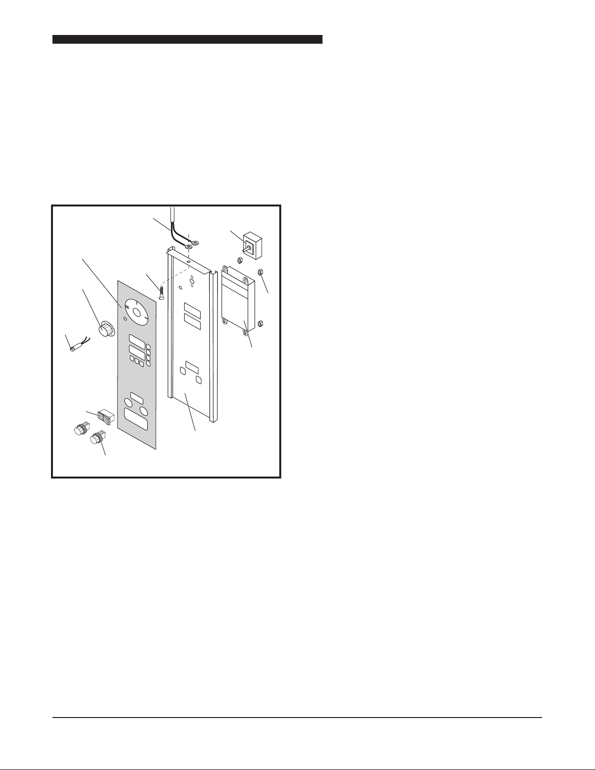
Power
Switch
Nut
XX
Controller
Temperature
Probe
Screw
Knob
Oven
Ready
Light
Fan
Switch
Fuse Holder &
Fuse (10 amp delay)
5
/
9
WARNING
Mylar
Control
Panel
XX CONTROL PANEL ASSEMBLY
WARNING: DISCONNECT OVEN FROM POWER
SOURCE BEFORE PERFORMING
ANY SERVICE.
Component Access Procedure
Remove screw at top center of XX Control Panel
assembly and slide Control Panel out to allow access
to Control Panel components.
XX Controller
1. Perform Component Access Procedure
2. Tag and disconnect wires from Controller.
3. Remove knobs from front of Control Panel.
4. Remove nuts securing Controller to Control Panel.
5. Remove Controller from rear of Control Panel.
6. Reverse procedure to install Controller.
OVEN READY Light
1. Perform Component Access Procedure.
2. Tag and disconnect wires to OVEN READY Light.
3. Remove OVEN READY Light from front of Control
Panel.
4. Reverse procedure to install OVEN READY Light.
Fan Switch
1. Perform Component Access Procedure.
POWER Switch
1. Perform Component Access Procedure.
2. Loosen setscrews and remove knob from POWER
Switch.
3. Tag and disconnect wires from POWER Switch..
4. Remove nut securing POWER Switch.
5. Remove POWER Switch from rear of Control
Panel.
6. Reverse procedure to install POWER Switch.
2. Tag and disconnect wires from Fan Switch.
3. Remove Fan Switch from front of Control Panel.
4. Reverse procedure to install Fan Switch.
LIGHT Switch
NOTE: LIGHT Switch is only on the 6/13 Oven.
1. Perform Component Access Procedure.
2. Tag and disconnect wires from LIGHT Switch.
3. Remove LIGHT Switch from front of Control Panel.
4. Reverse procedure to install LIGHT Switch.
Fuse and Fuse Holder
1. Remove Fuse Cap to replace Fuse.
2. Perform Component Access Procedure.
3. Tag and disconnect wires to Fuse Holder.
4. Remove nut securing Fuse Holder.
5. Remove Fuse Holder from front of Control Panel.
6. Reverse procedure to install a new Fuse Holder.
9
Service Manual for Electric Convection Oven
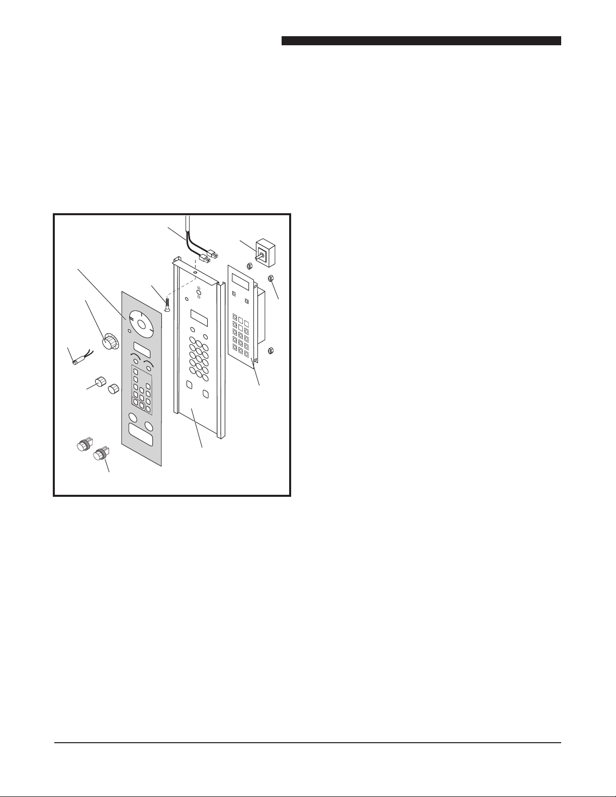
Power
Switch
Nut
Temperature
Probe
Screw
Knob
Oven
Ready
Light
Fuse Holder &
Fuse (10 amp delay)
5
/
9
WARNING
Lexan
Control
Panel
Knob
Digital
Control
Panel
Z
Controller
Z CONTROL PANEL ASSEMBLY
WARNING: DISCONNECT OVEN FROM POWER
SOURCE BEFORE PERFORMING
ANY SERVICE.
Component Access Procedure
Remove screw at top center of Z Control Panel assembly
and slide control panel out to allow access to Control
Panel components.
Z Controller
1. Perform Component Access Procedure.
2. Tag and disconnect wires from Controller.
3. Remove two knobs from front of Control Panel.
4. Remove four nuts securing Controller to Control
Panel.
5. Remove Controller from rear of Control Panel.
6. Reverse procedure to install a new Controller.
OVEN READY Light
1. Perform Component Access Procedure.
2. Tag and disconnect wires to OVEN READY Light.
3. Remove OVEN READY Light from front of panel.
4. Reverse procedure to install a new OVEN READY
Light.
Fuse and Fuse Holder Light
POWER Switch
1. Perform Component Access Procedure.
2. Loosen setscrew and remove knob from POWER
Switch.
3. Tag and disconnect wires from POWER Switch.
4. Remove nut securing POWER Switch.
5. Reverse procedure to install POWER Switch.
1. Remove Fuse Holder cap to replace Fuse.
2. Perform Component Access Procedure.
3. Tag and disconnect wires to Fuse Holder.
4. Remove nut securing Fuse Holder.
5. Remove Fuse Holder from front of Control Panel.
6. Reverse procedure to install a new Fuse Holder.
LIGHT Switch
NOTE: LIGHT Switch is only on the 6/13 Oven.
1. Perform Component Access procedure.
2. Tag and disconnect wires from LIGHT Switch.
3. Remove LIGHT Switch from front of Control Panel.
4. Reverse procedure to install a new LIGHT Switch.
10
Service Manual for Electric Convection Oven
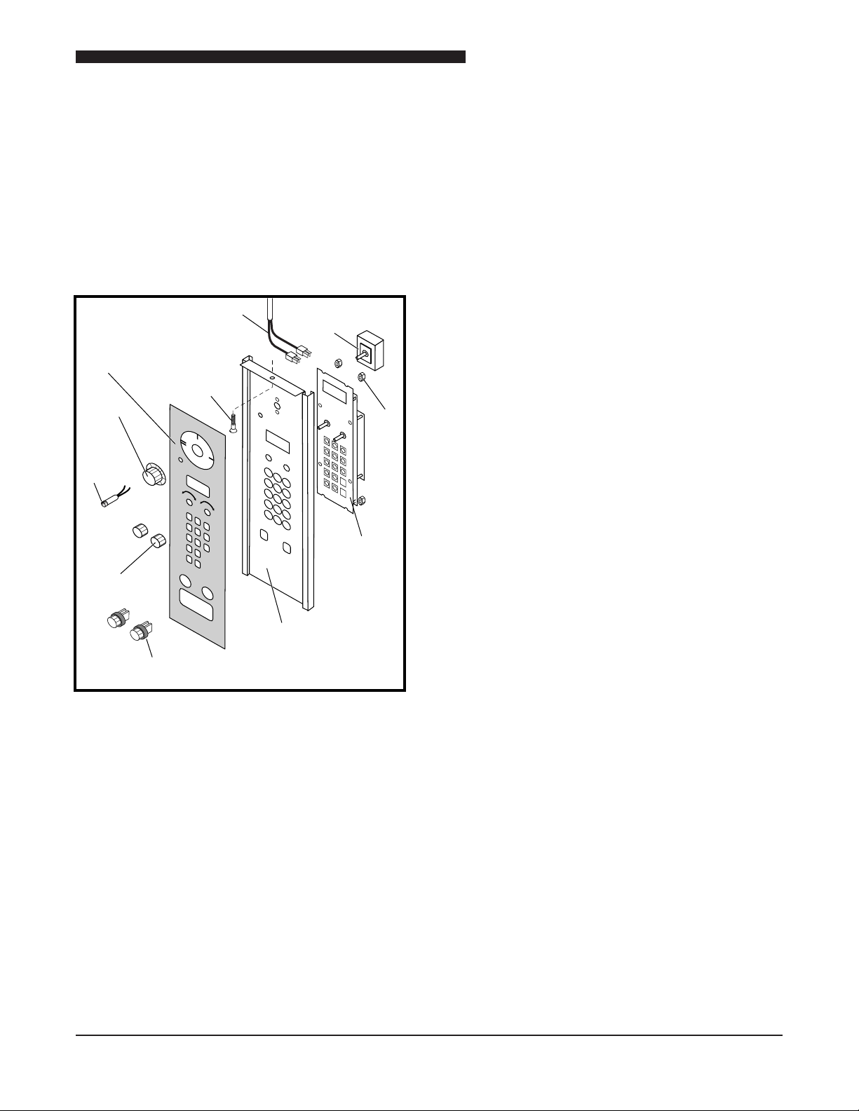
Power
Switch
Nut
Temperature
Probe
Screw
Knob
Oven
Ready
Light
Fuse Holder &
Fuse (10 amp delay)
5
/
9
WARNING
Lexan
Control
Panel
Knob
Digital
Control
Panel
ZX
Controller
ZX CONTROL PANEL ASSEMBLY
WARNING: DISCONNECT OVEN FROM POWER
SOURCE BEFORE PERFORMING
ANY SERVICE.
Component Access Procedure
Remove screw at top center of ZX Control Panel
assembly and slide control panel out to allow access
to Control Panel components.
ZX Controller
1. Perform Component Access Procedure.
2. Tag and disconnect wires from ZX Controller, &
tag wires.
3. Remove two knobs from front of Digital Control
Panel.
4. Remove four nuts securing ZX Controller to back
of Digital Control Panel.
5. Remove Controller from rear of Digital Control
Panel.
6. Reverse procedure to install ZX Controller.
OVEN READY Light
1. Perform Component Access Procedure.
2. Tag and disconnect wires to OVEN READY Light.
3. Remove OVEN READY Light from front of Digital
Control Panel.
POWER Switch
1. Perform Component Access Procedure.
2. Loosen set screw and remove knob from POWER
Switch.
3. Tag and disconnect wires from POWER Switch, &
tag wires.
4. Remove nut securing POWER Switch.
5. Reverse procedure to install a new POWER Switch.
4. Reverse procedure to install a new OVEN READY
Light.
LIGHT Switch
NOTE: LIGHT Switch is only on the 6/13 Oven.
1. Perform Component Access Procedure.
2. Tag and disconnect wires from LIGHT Switch.
3. Remove LIGHT Switch from front of Digital Control
Panel.
4. Reverse procedure to install a new LIGHT Switch.
Fuse and Fuse Holder Light
1. Remove Fuse Holder Cap to replace Fuse.
2. Perform Component Access Procedure.
3. Tag and disconnect wires to Fuse Holder.
4. Remove nut securing Fuse Holder.
5. Remove Fuse Holder from front of Digital Control
Panel.
6. Reverse procedure to install a new Fuse Holder.
11
Service Manual for Electric Convection Oven
Temperature
Probe
Screw
ZZ
Control
Panel
Relay
Board
Transformer
208/240V
WARNING
POWER
Oven
Control
Power
Switch
Fuse Holder &
Fuse (10 amp delay)
ZZ CONTROL PANEL ASSEMBLY
WARNING: DISCONNECT OVEN FROM POWER
SOURCE BEFORE PERFORMING
ANY SERVICE.
Component Access Procedure
Remove screw at top center of ZZ Control Panel
assembly and slide Control Panel assembly out to
allow access to Control Panel components.
ZZ Oven Control
1. Perform Component Access Procedure.
2. Tag and disconnect wires from ZZ Oven Control.
3. Remove two screws securing ZZ Oven Control to
Control Panel and remove Oven Control.
4. Reverse procedure to install a new ZZ Oven Control.
Fuse and Fuse Holder Light
1. Remove Fuse Holder Cap to replace Fuse.
2. Perform Component Access Procedure.
3. Tag and disconnect wires to Fuse Holder.
4. Remove nut securing Fuse Holder.
5. Remove Fuse Holder from front of Control Panel.
6. Reverse procedure to install a new Fuse Holder.
POWER Switch
1. Perform Component Access Procedure.
2. Tag and disconnect wires from POWER Switch.
3. Disengage POWER Switch from retainer and
4. Reverse procedure to install a new POWER Switch.
12
remove through front of Control Panel.
Service Manual for Electric Convection Oven
Power
Switch
Buzzer
1-Hour
Timer
Knob
Oven
Ready
Light
2-speed
Fan
Switch
Fuse Holder & Fuse
(10 amp delay)
Thermostat
Interior Light
Switch
Mylar,
Electric
Cook/Timer
Control Panel
6
/
13
Screw
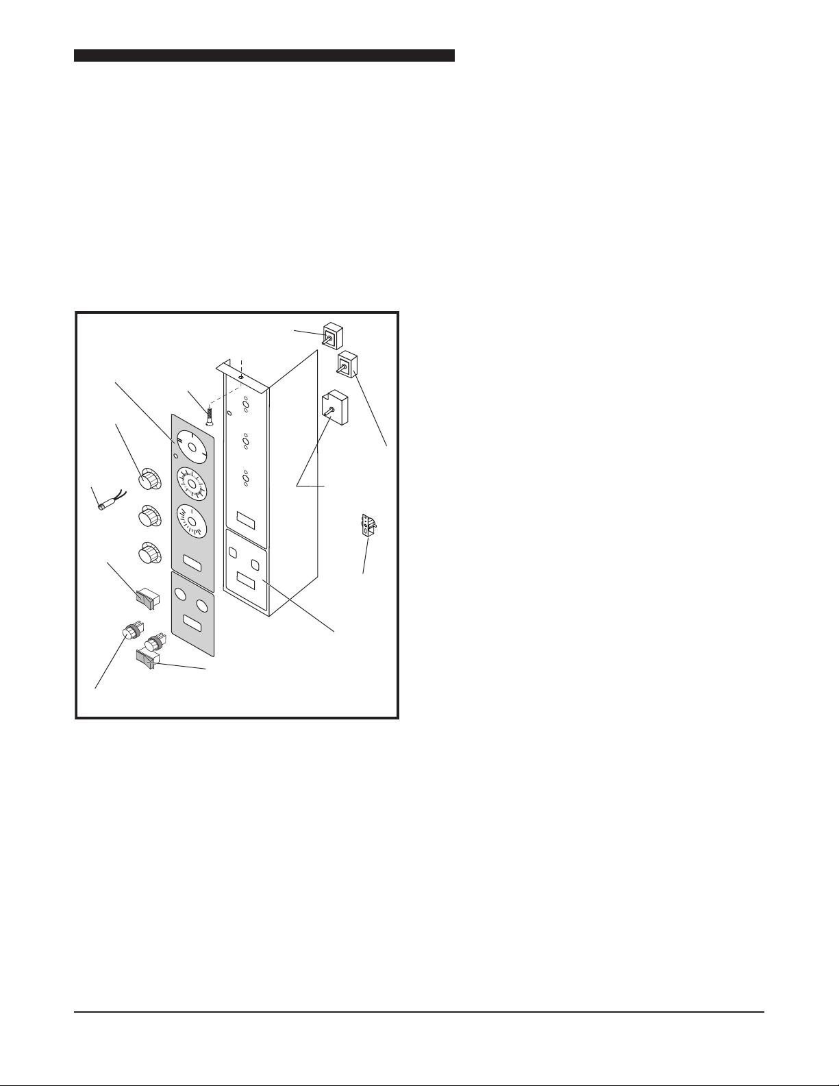
6/13 & 5/9 V CONTROLLER ASSEMBLY
& “E”SERIES-ELECTRO MECHANICAL
CONTROLLER ASSEMBLY
WARNING: DISCONNECT OVEN FROM POWER
SOURCE BEFORE PERFORMING
ANY SERVICE.
Component Access Procedure
Remove screw at top center of Control Panel assembly
and slide Control Panel assembly out to allow access
to Control Panel components.
1 - Hour TIMER
1. Perform Component Access Procedure.
2. Loosen set screw and remove 1 - Hour TIMER.
3. Remove nut securing 1 - Hour TIMER and remove
timer.
4. Reverse procedure to install 1 - Hour TIMER.
OVEN READY Light
1. Perform Component Access Procedure.
2. Tag and disconnect wires to OVEN READY Light.
3. Remove OVEN READY Light from front of Control
Panel.
4. Reverse procedure to install OVEN READY Light.
Fan Switch
1. Perform Component Access Procedure.
2. Tag and disconnect wires from Fan Switch.
3. Remove Fan Switch from front of Control Panel.
4. Reverse procedure to install Fan Switch.
POWER Switch
1. Perform Component Access Procedure.
2. Loosen set screws and remove knob from POWER
Switch.
3. Tag and disconnect wires from POWER Switch.
4. Remove nut securing POWER Switch and remove
POWER Switch.
5. Reverse procedure to install POWER Switch.
TEMPERATURE Control
Refer to THERMOSTAT in this section.
LIGHT Switch
NOTE: LIGHT Switch is only on the 6/13 Oven.
1. Perform Component Access Procedure.
2. Tag and disconnect wires from LIGHT Switch.
3. Remove LIGHT Switch from front of Control Panel.
4. Reverse procedure to install LIGHT Switch.
Fuse and Fuse Holder Light
1. Remove Fuse Holder Cap to replace Fuse.
2. Perform Component Access Procedure.
3. Tag and disconnect wires to Fuse Holder.
4. Remove nut securing Fuse Holder.
5. Remove Fuse Holder from front of Control Panel.
6. Reverse procedure to install Fuse Holder.
Buzzer
1. Perform Component Access Procedure.
2. Tag and disconnect wires from Buzzer.
3. Remove screw securing Buzzer to back of Control
Panel and remove Buzzer.
4. Reverse procedure to install Buzzer.
13
Service Manual for Electric Convection Oven
Power
Switch
Temperature
Probe
Knob
Oven
Ready
Light
Fuse Holder &
Fuse (10 amp delay)
5
/
9
WARNING
Mylar
Panel
Digital
Control
Panel
Screw
1
2
3
4
5
Transformer
Contactor
Terminal
Block
E3P
Controller
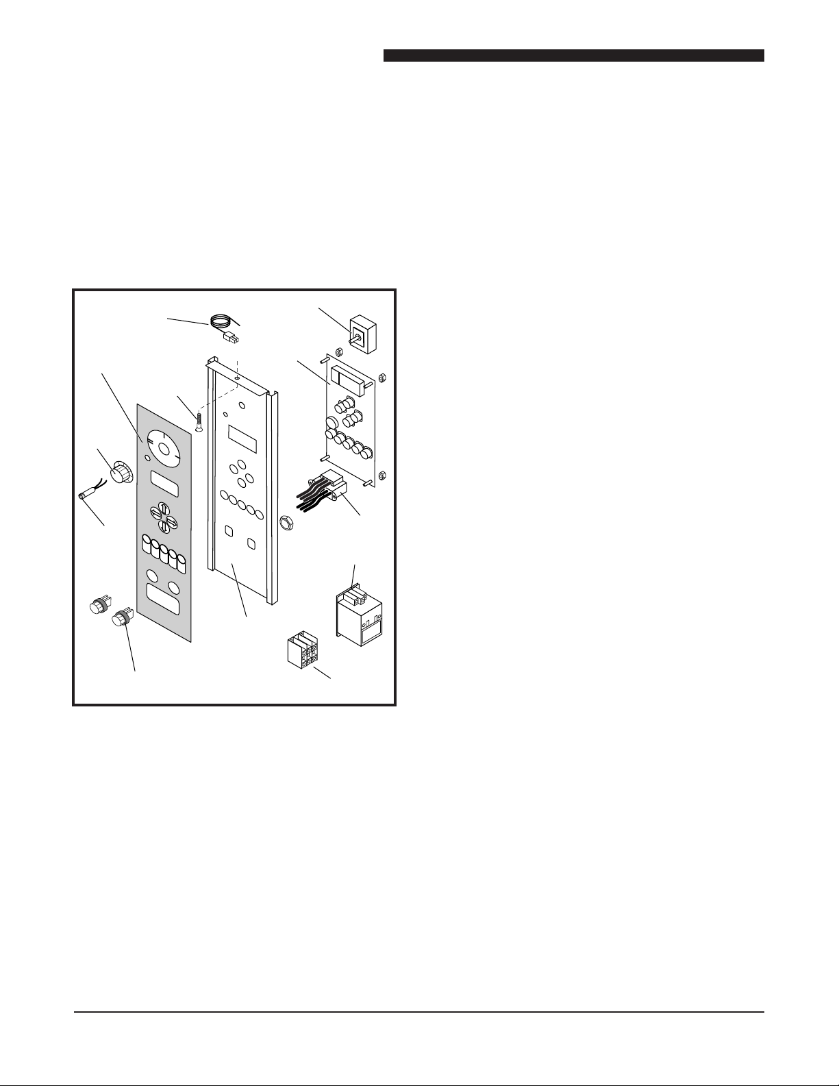
59-E3P OVEN CONTROLS
WARNING: DISCONNECT OVEN FROM POWER
SOURCE BEFORE PERFORMING
ANY SERVICE.
Component Access Procedure
Remove screw at top center of 59-E3P Control Panel
assembly and slide Control Panel assembly out to allow
access to Control Panel components.
Controller
1. Perform Component Access Procedure.
2. Tag and disconnect wires from Controller.
3. Remove nuts securing Controller to Control Panel.
4. Remove Controller from rear of Control Panel.
5. Reverse procedure to install a new Controller.
OVEN READY Light
1. Perform Component Access procedure.
2. Tag and disconnect wires to OVEN READY Light.
3. Remove OVEN READY Light from front of panel.
4. Reverse procedure to install a new OVEN READY
Light.
NOTE: Transformer, Contactor, and Terminal Block are
mounted on a panel behind the Oven Control.
Fuse and Fuse Holder Light
POWER Switch
1. Perform Component Access Procedure.
2. Loosen set screws and remove knob from POWER
Switch.
3. Tag and disconnect wires from POWER Switch.
4. Remove nut securing POWER Switch and remove
POWER Switch.
1. Remove Fuse Holder Cap to replace Fuse.
2. Perform Component Access Procedure.
3. Tag and disconnect wires to Fuse Holder.
4. Remove nut securing Fuse Holder.
5. Remove Fuse Holder from front of Control Panel.
6. Reverse procedure to install a new Fuse Holder.
Transformer
Refer to TRANSFORMER in this section.
Contactor
1. Perform Component Access Procedure.
2. Tag and disconnect wires to Contactor.
3. Remove four nuts and remove Contactor.
4. Reverse procedure to install a new Contactor.
Terminal Block
5. Reverse procedure to install a new POWER Switch.
14
1. Perform Component Access Procedure.
2. Tag and disconnect wires to Terminal Block.
3. Remove four nuts and remove Terminal Block.
4. Reverse procedure to install a new Terminal Block.
Service Manual for Electric Convection Oven
CONTROL
CIRCUIT
BOARD
PROBE
TRANS.
RELAY
COM
Blue Wire (Existing)
Purple Wire
(Existing)
Wire Nut
#2 White Wire (New)
#1 Blue Wire
(New)
#32 Black Wire
(Exisiting)
#3 Black Wire (New)
NO NC
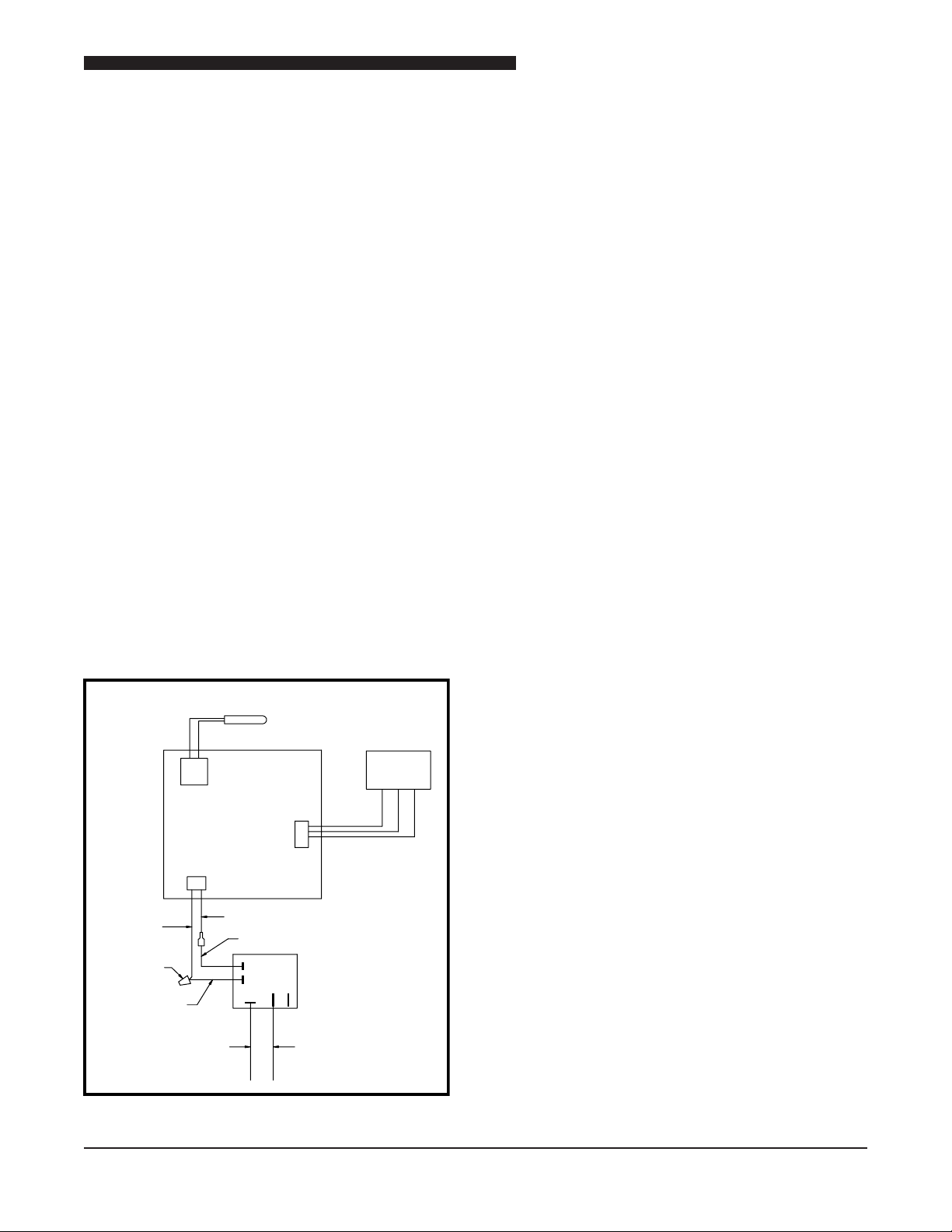
CONTROL CIRCUIT BOARD REPLACEMENT
WARNING: DISCONNECT OVEN FROM POWER
SOURCE BEFORE PERFORMING
ANY SERVICE.
The Control Circuit Board is used only in 5/9
convection ovens used by Popeye’s Chicken or
Churches Chicken.
1. Remove screw at top center of Control Panel
assembly and slide Control Panel out to allow
access to the Control Circuit Board.
2. Remove the two and four wire connectors from
the Control Circuit Board.
3. Remove the Probe connector from the Control
Circuit Board.
4. Remove the defective Control Circuit Board.
5. Install the replacement Control Circuit Board.
6. Attach the two and four wire connectors.
7. Attach the Probe connector.
8. Mount the Relay to the Control Panel below the
Control Circuit Board. DO NOT MOUNT THE
RELAY ON THE CONTROL CIRCUIT BOARD.
9. Attach the new wires #1, #2 and # 3 to the relay,
refer to the gure above for details.
10. Remove the wire nut that secures the 3 black
and 1 purple wire, separate the purple wire from
the bundle.
11. Referring to the gure above connect the #3 black
wire from the relay to the bundle black wires that
contained the purple wire removed in the previous
step and reattach the wire nut.
12. Referring to the gure above connect the purple
wire removed in step 10 to the blue wire and attach
a wire nut.
13. Referring to the gure above disconnect the #32
black wire from the blue wire.
14. Connect the #32 black wire to the common terminal
on the relay.
15. Connect the #2 white wire to the blue wire coming
from the relay and attach a wire nut.
16. Close the Control Panel and reattach its mounting
screw.
17. Proceed to the Control Circuit Board Jumper Setting
Instructions.
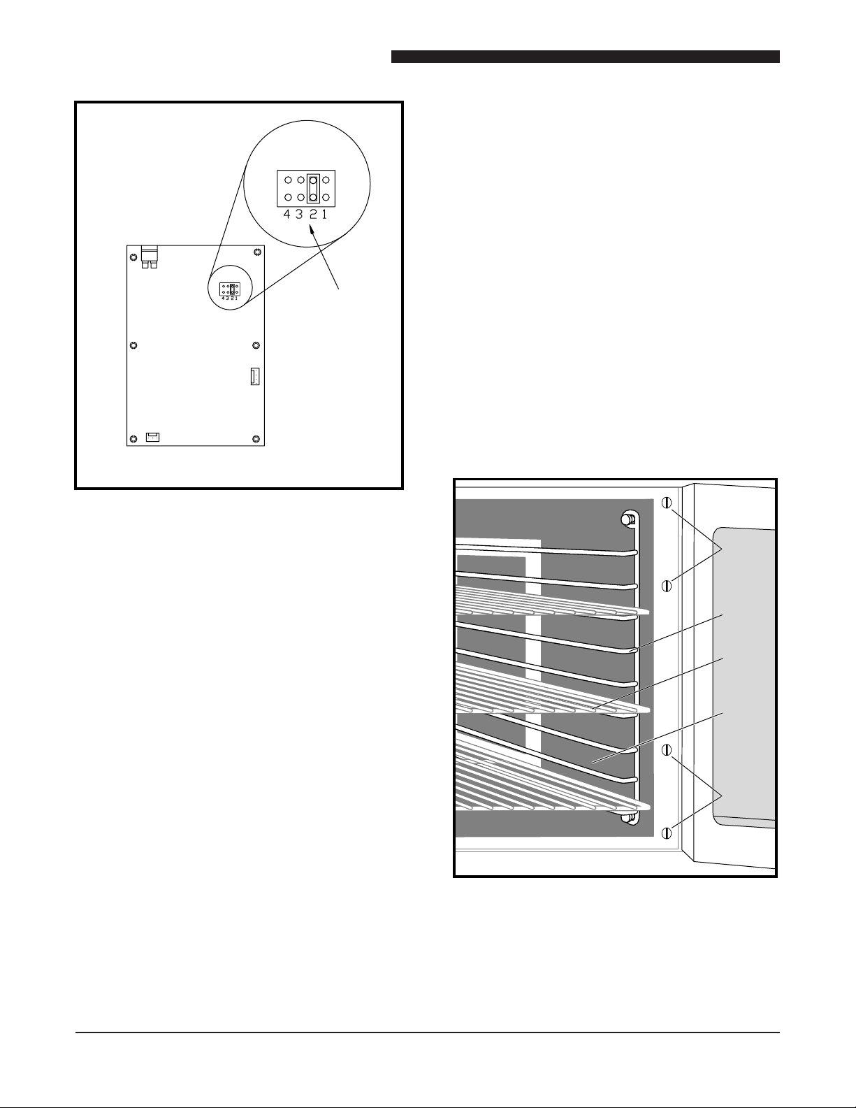
CONTROL CIRCUIT BOARD JUMPER
SETTINGS
The Control Circuit Board is shipped with the jumper
in position 3. Position 1 loads Churches Chicken’s
default settings. Position 2 loads Popeye’s Chicken’s
default settings.
Single Menu Jumper Setting
(Churches or Popeye’s)
1. Turn the power off to the unit.
2. Remove screw at top center of Control Panel
assembly and slide Control Panel out to allow
access to the Control Circuit Board.
3. Place the jumper in the #3 position, see the diagram
below.
15
Service Manual for Electric Convection Oven
Screws
Rack
Shelf
Right
Inside
Panel
Screws
JUMPER
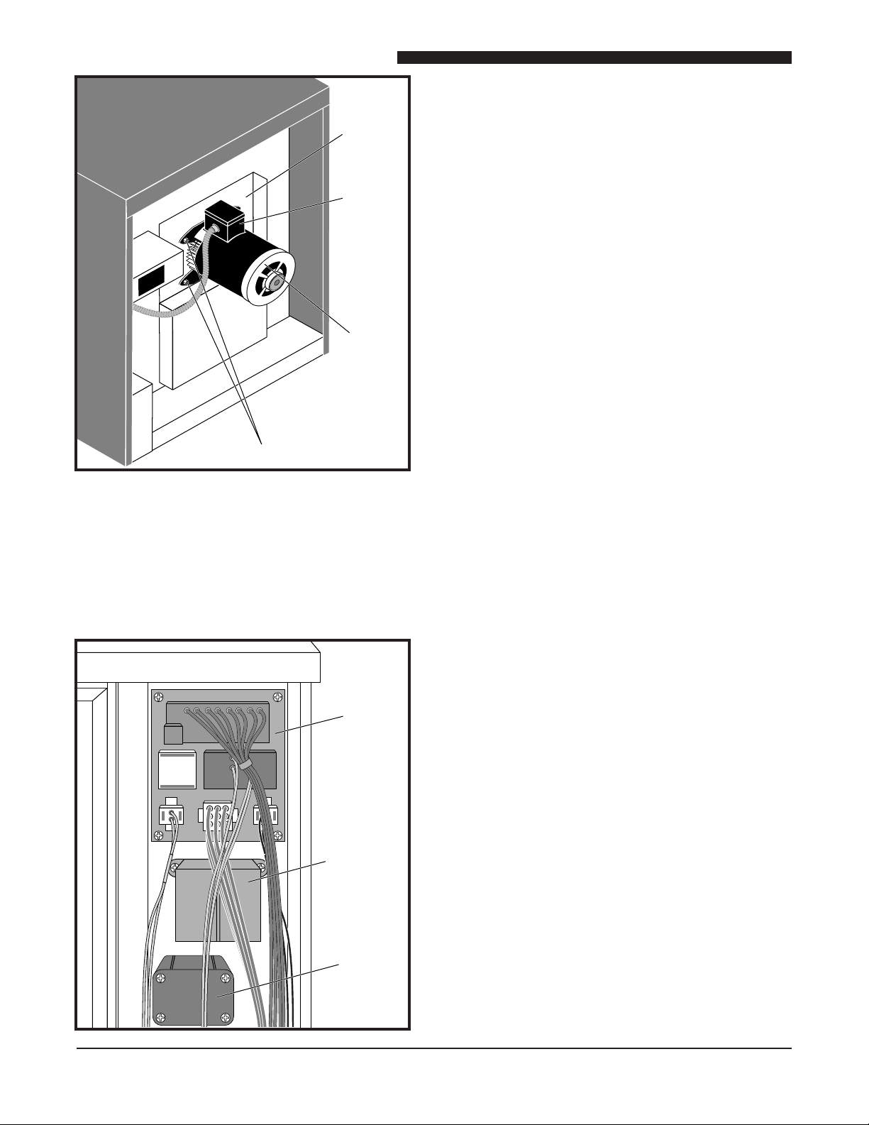
MOTOR
The motor is attached to the right side of the oven in
the following models:
• 5/9 Series Oven
• 5/9 The Oven
• 59-E3C Oven
• 59-E3P Oven
JUMP ER
JUMPER
POSITIONS
View of Back of Control Board
4. Reattach the Control Panel.
5. Turn the oven on and check the parameter settings.
6. Refer to the Operation & Installation Manual for
programming instructions.
Seven Menu Jumper Settings
(Popeye’s Chicken only)
1. Turn the power off to the unit.
The motor is attached to the back of the oven in the
following models:
• 6/13 The Oven
• “E” Series Oven
Side Mounted Motor
WARNING: DISCONNECT OVEN FROM POWER
SOURCE BEFORE PERFORMING
ANY SERVICE.
2. Remove screw at top center of Control Panel
assembly and slide Control Panel out to allow
access to the Control Circuit Board.
3. Place the jumper in the #4 position; see the diagram
above for jumper location.
4. Reattach the Control Panel.
5. Turn the oven on and check for parameter settings.
6. Refer to the Operation & Installation Manual for
programming instructions.
16
1. Open Oven Doors.
2. Remove shelves.
3. Remove two side racks.
4. Remove four screws attaching right inside panel and
remove panel to gain access to Motor Terminals.
Service Manual for Electric Convection Oven
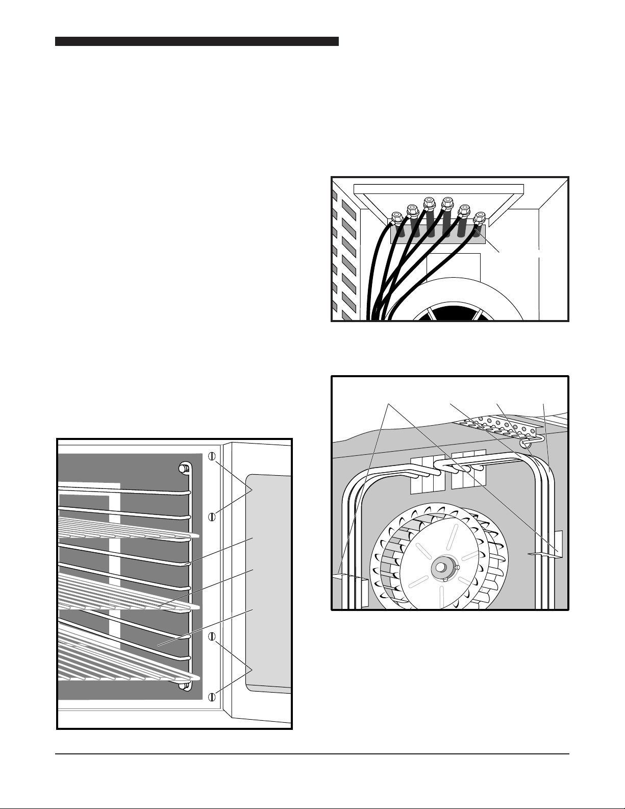
Inside back panel
Fan
Set
Screws
Nut
Mounting
Plate
Motor
Junction
Box
Rack
Back
Panel
Light
Bulb
Panel
ShelfFan
Rear Mounted Motor
WARNING: DISCONNECT OVEN FROM POWER
SOURCE BEFORE PERFORMING
ANY SERVICE.
1. Open Oven Doors.
2. Remove shelves.
3. Remove two side racks.
4. Remove four screws attaching back plate and
remove back plate to access Motor.
5. Inside the Oven, loosen setscrews on Blower (Fan)
and remove Fan from Motor Shaft.
6. Remove right side access panel.
7. At right side of oven, label and disconnect motor
wires at Motor Junction Box.
8. Remove four nuts securing Motor to Mounting Plate
and remove Motor.
9. Reverse procedure to install Motor.
5. Loosen setscrews on Blower (Fan) and remove
Fan from Motor Shaft.
6. At rear of oven, label and disconnect Motor wires
at Motor Junction Box.
7. Remove four nuts securing Motor to Mounting Plate
and remove Motor.
8. Reverse procedure to install Motor.
17
Service Manual for Electric Convection Oven
Nut
Mounting
Plate
Motor
Junction
Box
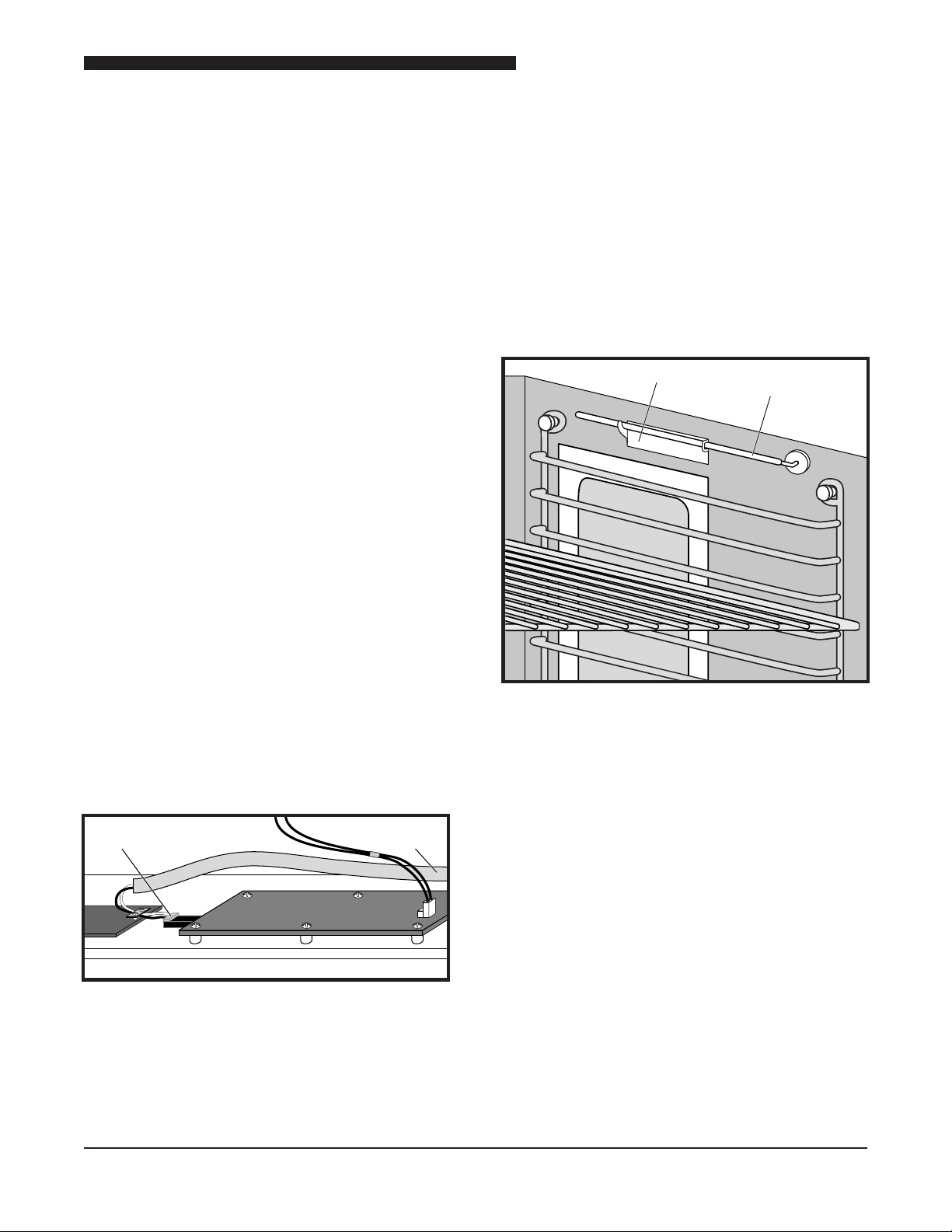
Motor
Relay
Board
Step-down
Transformer
Power
Transformer
STEP-DOWN TRANSFORMER
WARNING: DISCONNECT OVEN FROM POWER
SOURCE BEFORE PERFORMING
ANY SERVICE.
NOTE: Used on the 59-E3C and 59E3P oven.
Transformer is located behind Control Panel.
1. Remove screw at top center of Control Panel
assembly and slide Control Panel out to allow
access to the Step-Down Transformer.
2. Label and disconnect wires from Step-Down
Transformer.
3. Re m o v e two screws securing Step-Dow n
Transformer to panel and remove Step-Down
Transformer.
4. Reverse p r oc e d u re t o i n sta l l Step-Dow n
Transformer.
POWER TRANSFORMER
WARNING: DISCONNECT OVEN FROM POWER
SOURCE BEFORE PERFORMING
ANY SERVICE.
NOTE: Used on ovens with the Model 59-ZZ controller
or 5/9 ZZ Controller. Power Transformer is
located behind Control Panel.
1. Remove screw at top center of Control Panel
assembly and slide Control Panel out to allow
access to The Power Transformer.
2. Label a n d disconne c t w i res from Po w e r
Transformer.
3. Remove four screws attaching Power Transformer
to panel and remove Power Transformer.
4. Reverse procedure to install Power Transformer.
18
3-RELAY PRINTED CIRCUIT BOARD
(Relay Board)
WARNING: DISCONNECT OVEN FROM POWER
SOURCE BEFORE PERFORMING
ANY SERVICE.
NOTE: Used on ovens with the Model 59-ZZ Controller
or 5/9 ZZ Controller. PCB is located behind
Control Panel.
1. Remove screw at top center of Control Panel
assembly and slide Control Panel out to allow
access to the Relay Board.
2. Label and disconnect wires to Relay Board.
3. Remove four screws attaching Relay Board
assembly and remove Relay Board.
4. Reverse procedure to install a new Relay Board.
Service Manual for Electric Convection Oven
To RTD probe
in oven
Typical
board connection
Bracket Thermostat
Probe
RTD PROBE
WARNING: DISCONNECT OVEN FROM POWER
SOURCE BEFORE PERFORMING
ANY SERVICE.
The RTD Probe is located parallel to the oven door
at the front of the oven cavity for the following ovens:
5/9 The Oven
X Controller
XX Controller
Z and ZX Controller
ZZ Controller
The RTD Probe is located at the top center of the right
wall for the following ovens:
6/13 The Oven
X Controller
XX Controller
Z and ZX Controller
THERMOSTAT
WARNING: DISCONNECT OVEN FROM POWER
SOURCE BEFORE PERFORMING
ANY SERVICE.
The Thermostat is located on the V Controller and
the Thermostat Probe is located in the upper right of
oven. The Thermostat Probe provides temperature
information back to the Thermostat. The capillary tube
from the Thermostat to the Thermostat Probe is covered
with a berglass sleeve.
The RTD Probe is mounted on the top right center
wall for the following ovens:
59-E3C and 59-E3P ovens
CCSI Controller
1. Remove screw at top center of Control Panel
assembly and slide Control Panel out to allow
access to the RTD Probe connection on the Relay
Board.
2. Disconnect RTD Probe connector from Control
Board.
3. Remove RTD Probe from inside of the oven and
pull connector through side of oven to remove.
NOTE: When removing the Thermostat be careful not
to bend the capillary tube at a sharp angle to
prevent kinking.
1. Remove screw at top center of Control Panel
assembly and slide Control Panel out to allow
access to the Thermostat Probe capillary tube.
2. Open Oven Door and carefully remove Thermostat
Probe from bracket at upper right side of the oven.
2. Pull Thermostat Probe through the oven sidewall.
3. Remove Thermostat knob from front of V Controller
assembly.
4. Tag and disconnect wires from back of Thermostat.
5. Remove nut securing the Thermostat to front of V
Controller assembly.
4. Reverse procedure to install a new RTD Probe.
6. Pull Thermostat off rear of V Controller assembly.
7. Reverse procedure to install a new Thermostat.
Be sure berglass insulation is on capillary tube
to Thermostat Probe.
19
Service Manual for Electric Convection Oven
Thermostat
Probe
Thermostat
Probe
Oven
Sidewall
Bracket
Backup
Toggle Switch
Mounting
Bracket
Temperature
Plate
Thermostat
Probe
Side
Access
Panel
Knob
Screw
Thermostat
KX THERMOSTAT
WARNING: DISCONNECT OVEN FROM POWER
SOURCE BEFORE PERFORMING
ANY SERVICE.
The KX (Back up)Thermostat is used on the 59-E3C
and 59-E3P Ovens as an Oven Backup Thermostat.
This Thermostat is located behind the right access
panel, next to the Motor. The Thermostat Probe is
located inside the oven parallel to the Oven Door on
the top of the open cavity.
NOTE: When removing the KX Thermostat be careful
not to bend the capillary tube at a sharp angle
to prevent kinking.
1. Open Oven Door and carefully remove Thermostat
Probe from upper right front of the Oven.
2. Pull Thermostat Probe through the oven sidewall.
3. Remove two screws then remove side access
panel.
4. Remove two screws and remove mounting bracket.
5. Tag and disconnect wires from KX Thermostat.
6. Remove knob from KX Thermostat.
7. Remove nut securing KX Thermostat,
8. Pull KX Thermostat off mounting bracket.
9. Reverse procedure to install a new KX Thermostat.
Be sure berglass insulation is on capillary tube to
Temperature Probe.
BACKUP TOGGLE SWITCH
WARNING: DISCONNECT OVEN FROM POWER
SOURCE BEFORE PERFORMING
ANY SERVICE.
1. Remove two screws then remove side access
panel.
2. Remove two screws and remove mounting bracket.
3. Tag and disconnect wires to Backup Toggle Switch.
4. Remove nut securing Backup Toggle Switch.
20
5. Pull Backup Toggle Switch off mounting bracket.
6. Reverse procedure to install a new Backup Toggle
Switch.
Service Manual for Electric Convection Oven
Screws
Rack
Shelf
Right
Inside
Panel
Screws
Disconnect
wires
Disconnect
wires
Brackets
Inner
Element
Center
Element
Outer
Element
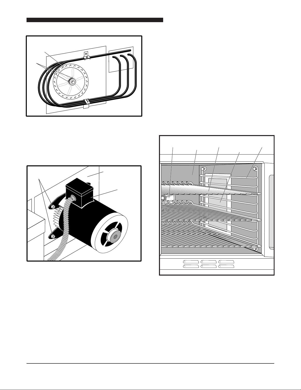
ELEMENTS
The Elements are attached inside of the oven on the
right side in the following models:
5/9 Series Oven 59-E3C Oven
5/9 The Oven 59-E3P Oven
The Elements are attached inside the oven on the back
in the following models.
6/13 The Oven “E” Series Oven
For both the side and back mounted locations, the
Elements consists of an inner Element, a center Element
and an outer Element. When replacing Elements be
sure to use the correct Element.
Side Mounted Elements
WARNING: DISCONNECT OVEN FROM POWER
SOURCE BEFORE PERFORMING
ANY SERVICE.
1. Inside oven, remove shelves and racks.
3. Remove right side panel as described in RIGHT
SIDE PANEL REMOVAL to gain access to the
Element connections.
4. Remove screws securing cover over heater wire
terminals on right side of oven.
5. Tag and disconnect Element wires at the terminals.
6. Remove the four screws securing the terminal plate.
7. Open Oven Door.
2. Remove four screws securing right side panel inside
oven and remove panel. This allows access to the
Blower and the Elements.
8. Remove the two brackets securing the Elements
around the Blower.
9. Slide Element out through inside of oven.
10. Reverse procedure to install an Element.
NOTE: Element lead wires should be torqued to
30 inch pounds.
21
Service Manual for Electric Convection Oven
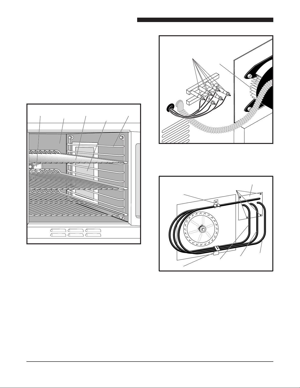
Rack
Back
Panel
Light
Bulb
Panel
ShelfFan
Fan
Terminals
Outside back panel
Inside back panel
Bracket
Screws
Terminal Plate
Inner
Element
Center
Element
Outer
Element
Bracket
Back Mounted Elements
WARNING: DISCONNECT OVEN FROM POWER
SOURCE BEFORE PERFORMING
ANY SERVICE.
1. Inside oven, remove shelves and racks.
2. Remove four screws securing Back Panel inside
oven and remove panel. This allows access to the
Blower and the Elements.
5. Open oven door.
3. Remove screws securing cover over heater wire
terminals on back of oven on the upper left.
4. Tag and disconnect Element wires at the terminals.
6. Remove the four screws securing the terminal plate
to the oven interior.
7. Remove the two clamps securing the Elements
around the Blower.
8. Slide Element assembly out through inside of oven.
9. Reverse procedure to install Elements.
NOTE: Element lead wires should be torqued to 30
inch pounds.
22
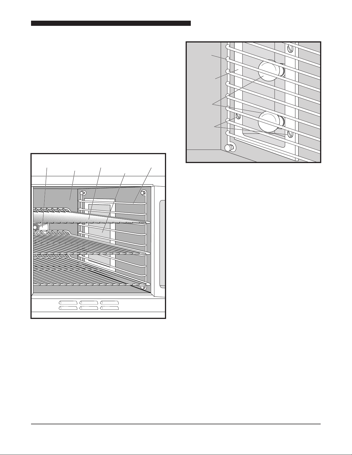
OVEN LIGHTS
Rack
Back
Panel
Light
Bulb
Panel
ShelfFan
Right Side
Rack
Light
Access
Panel
Light
Bulbs
Screws
Oven lights are located on the right side of the oven. The
light bulbs are replaced from inside the oven. The light
sockets are replaced by removing the right side panel.
WARNING: DISCONNECT OVEN FROM POWER
SOURCE BEFORE PERFORMING
ANY SERVICE.
1. Open Oven Door.
2. Remove shelves and right side rack to access Light
Bulbs.
Service Manual for Electric Convection Oven
DOORS
3. Remove four screws securing light bulb panel over
light bulbs and remove the panel.
4. Remove the faulty light bulb.
5. Reverse procedure to install a new light bulb.
The doors on all ovens are constructed similarly, except
the 6/13 oven has a turnbuckle assembly that causes both
the left and the right doors to open together. The left hand
doors are shown disassembled in the two illustrations.
WARNING: DISCONNECT OVEN FROM POWER
SOURCE BEFORE PERFORMING
ANY SERVICE.
Removal
1. Open oven door(s).
2. Remove Top Finish Piece.
3. Loosen setscrew on top and bottom Door Bearings.
4. Slide oven door off the hinges.
5. Reverse procedure to install Oven Door.
Disassembly
The oven door can be disassembled as necessary to
replace the handle, door glass, micro switch, bearing,
roller latch, door catch, and gaskets. On the 6/13 Dual
Door Ovens a turnbuckle assembly can also be replaced.
Gasket Replacement
The Gaskets are not attached to the oven door. These
gaskets are attached to the oven frame. The four gaskets
can be individually replaced.
NOTE: There are four separate Gaskets for the top,
bottom, and two sides. Each Gasket is replaced
independently.
23
 Loading...