

Page 1

Manuale d'officina
Workshop manual
Model Year 2000
DUCATI748RS
1
Page 2

Premessa
• Gli interventi descritti nel presente
manuale, richiedono esperienza e
competenza da parte dei tecnici
preposti, che sono invitati al pieno
rispetto delle caratteristiche
tecniche originali, riportate dal
Costruttore.
• Alcune informazioni sono state
appositamente omesse, poichè, a
nostro avviso, facenti parte
dell'indispensabile cultura tecnica
di base che un tecnico
specializzato deve possedere.
• Altre eventuali informazioni
possono essere dedotte dal
catalogo ricambi.
• Tutto il materiale da utilizzare
dovrà essere ordinato alla Ducati
Corse S.r.l.
• La Ducati Corse S.r.l. declina ogni
responsabilità per errori ed
omissioni di carattere tecnico,
prodotti nella redazione del
presente manuale e si riserva il
diritto di apportare qualsiasi
modifica richiesta dall'evoluzione
tecnologica dei suoi motocicli,
senza l'obbligo di divulgazione
tempestiva.
• Tutte le informazioni riportate,
sono aggiornate alla data di
stampa.
• Riproduzioni o divulgazioni anche
parziali degli argomenti trattati
nella presente pubblicazione, sono
assolutamente vietate. Ogni diritto
è riservato alla Ducati Corse S.r.l.,
alla quale si dovrà richiedere
autorizzazione (scritta)
specificandone la motivazione.
Foreword
• All operations described in this
manual must be carried out by
senior skilled technicians, who are
requested to strictly follow the
Manufacturer’s instructions.
• Some information has been
intentionally omitted, as, at our
advice, a specialized technician
must have this technical
background.
• Other information can be taken
from the spare parts catalogue.
• The orders for all the parts to be
used shall be placed at Ducati
Corse S.r.l.
• Ducati Corse S.r.l. declines all
responsibility for any technical
errors or omissions in this manual
and reserves the right to make
changes without prior notice.
• The information given in this
manual was correct at the time of
going to print.
• Reproduction and disclosure,
even partially, of the contents of
this manual are strictly forbidden
without prior written authorization
of Ducati Corse S.r.l., which has
exclusive right on this manual.
Applications for authorization
must specify the reasons for
reproduction or disclosure.
Ducati Corse S.r.l.
Ducati Corse S.r.l.
2
Page 3

Sommario
Contents
3
Page 4

Indicazioni generali 7
Simbologia di redazione 8
Consigli utili 9
Norme generali sugli interventi
riparativi 10
Generalità 11
Motore 12
Distribuzione 12
Alimentazione 13
Accensione 13
Candele 13
Lubrificazione 13
Raffreddamento 13
Trasmissione 14
Freni 14
Telaio 15
Sospensioni 15
Ruote 15
Pneumatici 16
Impianto elettrico 16
Pesi 16
Ingombri 16
Capacità 16
Interventi raccomandati 17
Operazioni per la
manutenzione del motore 18
Simboli identificazione
operazione 18
Tabella manutenzione motore 19
Scomposizione motore 21
Attrezzi speciali 23
Caratteristiche prodotti 25
Scarico olio 27
Scarico liquido di raffreddamento 27
Candele, cinghie e tenditori mobili 28
Testa 28
Cilindro e pistone 29
Coperchio alternatore 30
Alternatore e volano 32
Ingranaggi comando
distribuzione 33
Leveraggio selezione marce 34
Asta comando frizione 34
Frizione 35
Coperchio frizione 37
Ingranaggio frizione della
trasmissione primaria 38
Pompa olio 38
Ingranaggio albero motore della
trasmissione primaria 39
Pulegge rinvio distribuzione 40
Accessori basamento 41
Prigionieri, boccole e grani di
centraggio 42
Apertura carter 43
Elementi interni semicarter 45
Teste 47
Revisione motore 51
Pulizia dei particolari 52
Accoppiamenti 52
Sostituzione anelli di tenuta olio
(paraoli) 53
Anelli di arresto (seeger) 53
Cuscinetti 54
Cilindro 54
Pistone 55
Spinotto 55
Segmenti 56
Description 7
Graphic symbols 8
A word of advice 9
General advice on repair work 10
Description 11
Engine 12
Timing system 12
Fuel system 13
Ignition 13
Spark plugs 13
Lubrication 13
Cooling system 13
Transmission 14
Brakes 14
Frame 15
Suspension 15
Wheels 15
Tyres 16
Electrical system 16
Weights 16
Overall dimensions 16
Capacity 16
Maintenance schedule 17
Engine maintenance 18
Operation symbols 18
Engine service table 20
Engine disassembly 21
Special service tools for engine 24
Product specifications 26
Draining the oil 27
Draining the coolant 27
Spark plugs, timing belts
and mobile tensioners 28
Cylinder head 28
Cylinders and pistons 29
Generator cover 30
Generator and flywheel 32
Timing gears 33
Gear selector lever 34
Clutch push rod 34
Clutch 35
Clutch casing 37
Clutch primary drive gear 38
Oil pump 38
Crankshaft primary drive gear 39
Timing system rollers 40
Crankcase fittings 41
Stud bolts, centring bushes and
locators 42
Opening the crankcase 43
Parts inside the crankcase halves 45
Cylinder heads 47
Engine overhaul 51
Cleaning parts 52
Clearances and fits 52
Changing oil seals 53
Circlips 53
Bearings 54
Cylinders 54
Pistons 55
Gudgeon pins 55
Piston rings 56
Piston ring-ring groove gap 56
Piston ring end gap 57
Connecting rods 57
Data record sheet 59
Big-end bearing - Crankpin
clearance 63
4
Page 5

Accoppiamento segmento-cava
sul pistone 56
Accoppiamento segmenti-cilindro 57
Imbiellaggio 57
Scheda rilevamento dati 58
Accoppiamento semicuscinetti-perno
biella 63
Ricomposizione dell’imbiellaggio 64
Sede valvola 66
Guidavalvola 67
Valvola 68
Controllo tenuta valvole 69
Controllo profondità sacche
valvole 69
Bilancieri 70
Registri di apertura e chiusura molle 70
Albero a camme 71
Supporti albero a camme 71
Pulegge-Cinghie-Tenditori 72
Semicarter motore 72
Cuscinetti di banco 73
Circuito di lubrificazione 74
Schema di lubrificazione 75
Revisione componenti frizione 78
Gruppo di rinvio frizione 82
Gruppo cambio 83
Tamburo comando forcelle 84
Forcelle selezione marce 84
Spessorazione alberi cambio e
tamburo comando forcelle 85
Ricomposizione motore 87
Norme generali 88
Ricomposizione organi
della testa 89
Registrazione dei giochi 90
Registri di chiusura 91
Registri di apertura 92
Montaggio coperchietti laterali 92
Montaggio supporto tenditori 94
Montaggio raccordo uscita acqua 95
Coperchio aspirazione 95
Collettore di aspirazione 95
Chiusura semicarter 96
Rimontaggio leveraggio selezione
marce 100
Rimontaggio pulegge rinvio
distribuzione 102
Rimontaggio ingranaggi
distribuzione 103
Rimontaggio ingranaggio
trasmissione primaria 103
Rimontaggio volano e rotore
alternatore 104
Rimontaggio pompa acqua sul
coperchio alternatore 106
Rimontaggio coperchio
alternatore 108
Rimontaggio pompa olio 109
Rimontaggio coperchio frizione 109
Ricomposizione frizione 111
Controllo traferro sensori di fase e
numero di giri motore 113
Ricomposizione gruppi termici 114
Controllo altezza di “squish” 114
Verifica fasatura motore 115
Rimontaggio definitivo
gruppi termici 120
Coppie di serraggio motore 122
Reassembling the connecting
rods 64
Valve seats 66
Valve guides 67
Valves 68
Checking the valve seal 69
Checking the valve pocket depth 69
Rocker arms 70
Opening and closing adjusters Springs 70
Camshaft 71
Camshaft supports 71
Rollers - Belts - Tensioners 72
Crankcase halves 72
Main bearings 73
Lubrication circuit 74
Lubrication circuit diagram 75
Clutch overhaul 78
Clutch transmission unit 82
Gearbox 83
Selector drum 84
Gear selector forks 84
Shimming the gearbox shafts and
the selector drum 85
Engine reassembly 87
General instructions 88
Reassembling cylinder head parts 89
Adjusting clearance 90
Closing shims 91
Opening shims 91
Assembling side covers 92
Assembling tensioner support 94
Assembling water outlet
connector 95
Intake cover 95
Intake manifold 95
Closing the crankcase halves 96
Refitting the gear selector lever 100
Reassembly of the timing rollers 102
Refitting the timing gears 103
Reassembling the primary drive
gear 103
Reassembling the flywheel and the
generator rotor 104
Refitting the water pump to the
generator cover 106
Refitting the generator cover 108
Refitting the oil pump 109
Refitting the clutch casing 109
Clutch reassembly 111
Checking the air gap of the timing
and RPM sensors 113
Refitting the cylinders 114
Checking the “squish” height 114
Checking engine timing 115
Final reassembly of the cylinders 120
Torque settings, engine 124
5
Page 6

Mototelaio 127
Trasmissione secondaria 128
Messa a punto telaio 128
Messa a punto standard 129
Tabella taratura 135
Individuazione guasti 136
Coppie di serraggio mototelaio 140
Individuazione guasti impianto
elettrico 146
Schema impianto elettrico
principale 147
Frame 127
Final drive 128
Frame and suspension setup 128
Standard set-up 129
Set-up tables 135
Troubleshooting 136
Torque settings, frame 143
Troubleshooting of electric
system 146
Main wiring diagram 147
6
Page 7

Indicazioni generali
Description
7
Page 8
SIMBOLOGIA DI REDAZIONE
GRAPHIC SYMBOLS
• Per una lettura rapida e razionale
sono stati impiegati simboli che
evidenziano situazioni di massima
attenzione, consigli pratici o
semplici informazioni.
Nota
Prestare attenzione al
significato dei simboli, in quanto la
loro funzione è quella di non dovere
ripetere concetti tecnici o avvertenze
di sicurezza. Sono da considerare,
quindi, dei veri e propri
"promemoria". Consultare questa
pagina ogni volta che sorgeranno
dubbi sul loro significato.
❍
Questo simbolo, posto all’inizio
del testo, identifica una operazione o
un intervento che costituisce parte
integrante di una procedura di
smontaggio.
●
Questo simbolo, posto all’inizio
del testo, identifica un dato o un
riferimento particolarmente
importante per l'operazione in
corso.
▲
Questo simbolo, posto all’inizio
del testo, identifica una operazione di
rimontaggio.
Tutte le indicazioni destro
o sinistro si riferiscono
al senso di marcia del
motociclo.
Attenzione
La non osservanza delle
istruzioni riportate può creare una
situazione di pericolo e causare gravi
lesioni personali e anche la morte.
Importante
Indica la possibilità di
arrecare danno al veicolo e/o
ai suoi componenti se le
istruzioni riportate non vengono
eseguite.
Note
Fornisce utili
informazioni sull'operazione in
corso.
• For easy and rational reading, this
manual uses graphic symbols for
highlighting situations in which
maximum care is required,
practical advice or simple
information.
Note
Please pay maximum attention
to these symbols as they are meant
for not repeating technical concepts
or safety rules. They must be
considered real “notes”. Read this
page in case of doubts on their
meaning.
❍
This symbol at the start of an item
of text indicates an operation which
is part of a disassembly procedure.
●
This symbol at the start of an item
of text indicates a piece of
information or a reference item
which is particularly important for the
current operation.
▲
This symbol at the start of an item
of text indicates a reassembly
operation.
Left-hand and right-hand in the
descriptions of the motorcycle and
components refer to the left and
right of the machine as seen in the
direction of travel.
Warning
Failure to follow the
instructions given in text marked
with this symbol can lead to serious
personal injury or death.
Caution
Failure to follow the
instructions in text marked with this
symbol can lead to serious damage
to the motorcycle and/or its
components.
Note
This symbol indicates
additional useful information for the
current operation.
8
Page 9

CONSIGLI UTILI
A WORD OF ADVICE
• La Ducati consiglia, onde
prevenire inconvenienti e per il
raggiungimento di un ottimo
risultato finale, di attenersi
genericamente alle seguenti
norme:
• in caso di una probabile
riparazione valutare le impressioni
del Cliente, evidenzianti
anomalie di funzionamento del
motociclo, e formulare le
opportune
domande di chiarimento
sui sintomi dell’inconveniente;
• diagnosticare in modo chiaro le
cause dell’anomalia. Dal presente
manuale si potranno assimilare le
basi teoriche fondamentali, che
peraltro dovranno essere
integrate dall’esperienza
personale
• pianificare razionalmente la
riparazione onde evitare tempi
morti come ad esempio il prelievo
di parti di ricambio, la
preparazione degli attrezzi, ecc.;
• raggiungere il particolare
da riparare limitandosi
alle operazioni
essenziali.
• A tale proposito sarà di valido
aiuto la consultazione della
sequenza di smontaggio esposta
nel presente manuale.
• Ducati would like to offer a word
or two of advice on how to best
ensure an efficient, fault-free
customer service.
• When diagnosing breakdowns,
primary consideration should
always be given to what the
customer reports. Your questions
to the customer should aim to
clarify the problem a step at a
time and lead to an accurate
diagnosis of the source of the
trouble.
• Diagnose the problem
systematically and accurately
before proceeding further. This
manual provides the theoretical
background for troubleshooting to
be integrated with your own
personal experience.
• Repair work should be planned
carefully in advance to prevent
any unnecessary down-time, for
example picking-up of required
spare parts or arrangement of
required tools, etc.
• Limit the number of operations
needed to reach the part to be
repaired to the minimum.
• The disassembly procedures in
this manual describe the most
efficient way to reach a part to be
repaired.
9
Page 10

NORME GENERALI SUGLI
INTERVENTI RIPARATIVI
GENERAL ADVICE ON REPAIR
WORK
• Utilizzare sempre attrezzature di
ottima qualità.
• Utilizzare, per il sollevamento del
motoveicolo, attrezzatura
espressamente realizzata e
conforme alle direttive Europee.
• Mantenere, durante le operazioni,
gli attrezzi a portata di mano,
possibilmente secondo una
sequenza predeterminata e
comunque mai sul veicolo o in
posizioni nascoste o poco
accessibili.
• Mantenere ordinata e pulita la
postazione di lavoro.
• Sostituire sempre le guarnizioni,
gli anelli di tenuta e le copiglie con
particolari nuovi.
• Allentando o serrando dadi o viti,
iniziare sempre da quelle con
dimensioni maggiori oppure dal
centro; bloccare alla coppia di
serraggio prescritta seguendo un
percorso incrociato.
• Contrassegnare sempre particolari
o posizioni che potrebbero essere
scambiati fra di loro all’atto del
rimontaggio.
• Usare parti di ricambio originali
Ducati ed i lubrificanti delle
marche raccomandate.
• Usare attrezzi speciali dove
specificato.
• Consultare le Circolari Tecniche in
quanto potrebbero riportare dati di
regolazione e metodologie di
intervento maggiormente
aggiornate rispetto al presente
manuale.
• Always use top quality tools.
• Lift the motorcycle only with
devices in full compliance with
relevant European directives.
• During repair work always keep
the tools within reach, possibly in
the right order. Never put them
on the vehicle or in hardly
reachable places or somehow
hidden.
• Work place must be neat and
clean.
• During repair work always
change gaskets, seals and split
pins.
• When loosening or tightening
nuts and bolts, always start with
the largest and always start from
the center. Tighten nuts and bolts
working crossways; tighten to the
specified torque wrench settings.
• At disassembly, mark any parts
and positions which might easily
be confused at reassembly.
• Use Ducati original spare parts
only. Use the recommended
lubricants only.
• Use special service tools where
specified.
• Ducati Technical Bulletins often
contain up-dated versions of the
service procedures described in
this manual. Check the latest
Bulletins for details.
10
Page 11

Generalità
Description
Generalità / Description 11
Page 12

MOTORE
ENGINE
Bicilindrico ad “L” di 90°- ciclo otto
4 tempi.
Alesaggio:
88 mm
Corsa:
61,5 mm
Cilindrata totale:
748,1 cm
3
Rapporto di compressione:
12
±
0,2:1
Potenza max. all’albero (95/1/CE):
124 CV
al regime di:
11.500 min
-1
Coppia max. all’albero (95/1/CE):
7,85 kgm
al regime di:
9.500 min
-1
DISTRIBUZIONE
Doppio albero a camme in testa 4␣ valvole per cilindro con comando a
mezzo cinghia dentata e puleggia in
alluminio - sistema Desmodromico.
Diagramma distribuzione
Con Alzata:
1 mm
Aspirazione
Apertura:
30
°
P.P.M.S.
Chiusura:
62
°
D.P.M. I.
Scarico
Apertura:
74
°
P.P.M.I.
Chiusura:
38
°
D.P.M.S.
4-stroke 90
°
L
twin-cylinder (Otto engine).
Bore:
88 mm
Stroke:
61.5 mm
Capacity:
748.1 cu. cm
Compression ratio:
12
±
0.2:1
Max. power at crankshaft (95/1/EC):
124 HP
at:
11,500 rpm
Max. torque at crankshaft (95/1/EC):
7.85 kgm
at:
9,500 rpm
TIMING SYSTEM
Desmodromic valve timing gear.
Double overhead camshaft, 4 valves
per cylinder, driven by toothed belt
and aluminium roller.
Valve timing
Valve lift:
1 mm
Intake
Intake valve opens at:
30
°
before TDC
Intake valve closes at:
62
°
after BDC
Exhaust
Exhaust valve opens at:
74
°
before BDC
Exhaust valve closes at:
38
°
after TDC
Diametro valvole
Aspirazione:
36 mm
Scarico:
30 mm
Alzata valvole
Aspirazione:
12,5 mm
Scarico:
10,5 mm
Con Gioco Valvole:
0 mm
Il gioco di funzionamento delle
punterie, a motore freddo, deve
essere:
Gioco superiore (apertura)
Aspirazione:
0,15
÷
0,18 mm
Scarico:
0,25
÷
0,28 mm
Gioco inferiore (chiusura)
Aspirazione:
0,15
÷
0,18 mm
Scarico:
0,10
÷
0,13 mm
Se i giochi non rientrano nelle classi
sopra indicate, la testa va smontata
per ripristinare i corretti giochi valvola.
Valve diameter
Intake valve diameter:
36 mm
Exhaust valve diameter:
30 mm
Valve lift
Intake:
12.5 mm
Exhaust:
10.5 mm
With valve clearance:
0 mm
Tappet clearances (with the engine
cold):
Upper clearance (opening)
Intake:
0.15 -0.18 mm
Exhaust:
0.25 -0.28 mm
Lower clearance (closing)
Intake:
0.15 -0.18 mm
Exhaust:
0.10 -0.13 mm
If clearances are outside the ranges
specified above, the head must be
disassembled to reset the correct
valve clearance.
12 Generalità / Description
Page 13

ALIMENTAZIONE
FUEL SYSTEM
Iniezione elettronica indiretta
MARELLI del tipo
/N - CPU 1.6.
1 iniettore per cilindro.
Alimentazione:
benzina 95-98 RON
ACCENSIONE
Elettronica tipo I.A.W. a scarica
induttiva - generatore trifase
"DENSO" 520 W - volano in un solo
pezzo con flangia di supporto.
CANDELE
Marca:
CHAMPION
Tipo:
QA 503 V
LUBRIFICAZIONE
Forzata con pompa ad ingranaggi.
Con radiatore raffreddamento.
Capacita circuito:
3 l
Portata pompa:
3,2 l/min ogni 1.000 min
-1
MARELLI
/N - CPU 1.6 electronic
indirect fuel injection.
1 injector per cylinder
Fuel:
95-98 RON petrol
IGNITION
I.A.W electronic, inductive discharge
unit. Three-phase "DENSO"
generator, 520 W. Single-piece
flywheel with support flange.
SPARK PLUGS
Make:
CHAMPION
Type:
QA 503 V
LUBRICATION
Forced lubrication by gear pump.
With oil cooler.
Lubrication system capacity:
3 l
Pump flow rate:
3.2 l/min per 1,000 rpm.
RAFFREDDAMENTO
A liquido - Circuito chiuso con
radiatore curvo e termostato a
miscelazione.
Capacita circuito:
2,9 l
COOLING SYSTEM
Closed-circuit liquid cooling with
curved radiator and admixture
thermostat .
Circuit capacity:
2.9 l
Generalità / Description 13
Page 14

TRASMISSIONE
TRANSMISSION
Trasmissione primaria
Ad ingranaggi a denti diritti.
Pignone motore:
Z31
Corona frizione:
Z62
Rapporto di trasmissione:
2
÷
1
Cambio velocità
Con ingranaggi a denti diritti sempre
in presa, comando a pedale sul lato
sinistro del veicolo.
Rapporti di trasmissione
(Norme Cuna)
Marcia inserita
a
1
a
2
a
3
a
4
a
5
32/16
29/18
27/20
25/21
24/22
Primary transmission
Straight-tooth gears
Crankshaft sprocket:
31 teeth
Clutch crown wheel:
62 teeth
Primary reduction ratio:
2-1
Gearbox
Constant-mesh spur gears, direct
drive. Gear change pedal on LH side
of motorcycle.
Gearbox ratios
(Cuna Standard)
Gear engaged
st
1
nd
2
rd
3
th
4
th
5
32/16
29/18
27/20
25/21
24/22
a
6
23/23
Trasmissione secondaria
Pignone uscita cambio:
Z15
Corona posteriore:
Z38
Marca e tipo catena:
Regina 135ORNV4W
FRENI
Anteriore
A doppio disco diametro 320 mm
flottante con comando idraulico.
Diametro cilindro pompa (PSC 16):
16 mm
Diametro cilindro pinza (p4.30-34):
30-34 mm
Posteriore
A disco diametro 220 mm con
comando idraulico.
Diametro cilindro pompa (PS 11):
11 mm
Diametro cilindro pinza (P 32F):
32 mm
th
6
23/23
Final drive
Final drive sprocket:
15 teeth
Rear wheel sprocket:
38 teeth
Chain make and type:
Regina 135ORNV4W
BRAKES
Front brake
Twin 320 mm diam. floating discs,
hydraulically operated.
Master cylinder (PSC 16) diameter:
16 mm
Caliper slave cylinder (p 4-30-34)
diameter:
30-34 mm
Rear brake
220 mm diam. disc, hydraulically
operated.
Master cylinder (PS 11) diam.:
11 mm
Caliper slave cylinder (P 32F) diam.:
32 mm
14 Generalità / Description
Page 15

TELAIO
FRAME
Traliccio aperto con il motore
elemento stressato della struttura tubi tondi in acciaio, la carenatura, i
parafanghi, il cupolino e la sella sono
realizzati in fibra composita carbonio
e kevlar.
Interasse:
1410 mm
Avancorsa regolabile:
91,1
÷
97,1 mm
Inclinazione cannotto, angolo
regolabile:
23
°
30' - 24°30'
Ammortizzatore di sterzo ÖHLINS.
SOSPENSIONI
Anteriore
Forcella SHOWA a canne rovesciate
- freno idraulico in estensione,
compressione, precarico molla
regolabili.
Diametro steli:
43 mm
Corsa sull’asse gambe:
127 mm
Posteriore
Progressiva con
monoammortizzatore ÖHLINS con
corpo in alluminio - regolabile in
estensione, compressione e
precarico molla.
Corsa ammortizzatore:
74 mm (54 mm fino a tampone)
Escursione ruota:
130 mm
Trellis space frame with engine as
load bearing component. Steel round
tubes. Fairing, mudguards, front
fairing and seat in carbon fibre and
Kevlar.
Wheelbase:
1410 mm
Trail:
91.1 to 97.1 mm adjustable
Headstock rake:
23
°
30’ to 24° 30’ adjustable
ÖHLINS steering damper.
SUSPENSION
Front suspension
SHOWA inverted hydraulic fork; with
adjustable spring rebound,
compression and preload.
Leg diameter:
43 mm
Stanchion travel on slider:
127 mm
Rear suspension
Progressive linkage with ÖHLINS
aluminium-body monoshock.
Adjustable spring rebound,
compression and preload.
Shock travel:
74 mm (54 mm to buffer)
Rear wheel travel:
130 mm
WHEELS
RUOTE
Anteriore
Cerchio anteriore in lega di alluminio
a 5 razze.
Dimensioni:
MT 3,50 x 17"
Posteriore
Cerchio posteriore in lega di
alluminio a 5 razze.
Dimensioni :
MT 5,50 x 17"
Front wheel
Five-spoke aluminium alloy wheel.
Front rim size:
MT 3.50 x 17”
Rear wheel
Five-spoke aluminium alloy wheel.
Rear rim size:
MT 5.50 x 17”
Generalità / Description 15
Page 16

PNEUMATICI
TYRES
Anteriore
Marca e tipo:
MICHELIN
Dimensione:
120/70 ZR 17 TL
Posteriore
Marca e tipo:
MICHELIN
Dimensione:
180/55 ZR 17 TL
IMPIANTO ELETTRICO
Tensione impianto:
12 V
Alternatore:
12 V - 520 W
Batteria:
12 V - 4 Ah
PESI
Totale (con olio e acqua):
174 Kg
INGOMBRI
Front tyre
Make and type:
MICHELIN
Size:
120/70 ZR 17 TL
Rear tyre
Make and type:
MICHELIN
Size:
180/55 ZR 17 TL
ELECTRICAL SYSTEM
Voltage:
12V
Generator:
12 V - 520 W
Battery:
12 V - 4 Ah
WEIGHTS
Total weight (including oil and water):
174 Kg
OVERALL DIMENSIONS
Lunghezza totale:
2045 mm
Larghezza max.:
680 mm
Altezza max.:
1100 mm
Altezza sella:
800 mm
Altezza min. da terra:
130 mm
Altezza manubrio:
830 mm
Altezza pedane:
410 mm
CAPACITÀ
Serbatoio carburante:
17 l.
Overall length:
2045 mm
Overall width:
680 mm
Overall height:
1100 mm
Seat height:
800 mm
Min. ground clearance:
130 mm
Handlebar height:
830 mm
Front footpeg height:
410 mm
CAPACITY
Fuel tank capacity:
17 l.
16 Generalità / Description
Page 17

Interventi raccomandati
Maintenance schedule
Interventi raccomandati / Maintenance schedule
Generalità / Description 17
Page 18

Utilizzate solo ed esclusivamente
parti di ricambio originali Ducati e
prodotti per il serraggio, la tenuta e la
lubrificazione, consigliati e riportati
nella tabella: "Caratteristiche
prodotti".
OPERAZIONI PER LA
MANUTENZIONE DEL MOTORE
- Nella pagina che segue è riportata
la tabella di manutenzione motore,
nella quale sono elencati i più
importanti interventi e la relativa
periodicità.
- È della massima importanza
attenersi a tale programmazione, per
la manutenzione del motore.
SIMBOLI IDENTIFICAZIONE
OPERAZIONE
C = Controllo e regolazione
P = Pulizia
S = Sostituzione
= Solo in sala prova
*
# = Sostituire ogni tre serraggi
(considerando il serraggio iniziale del
fornitore).
Importante
Ad ogni revisione, smontare
completamente il motore e sostituire
tutte le parti anche soltanto
apparentemente danneggiate, oltre
che attenersi alla tabella di
manutenzione. Dopo la revisione:
1000 km, il motore non è più
utilizzabile in gara.
Use Ducati original spare parts only.
Use only the recommended threadlockers, sealants and lubricants
specified in table "Product
specifications".
ENGINE MAINTENANCE
- The next page provides an engine
service table listing the most
important maintenance operations
and recommended intervals.
- It is very important that you strictly
follow the recommended
maintenance schedule.
OPERATION SYMBOLS
C = Check and adjust
P = Clean
S = Change
= do this in a test room
*
# = Replace every three tightenings
(including the original manufacturer
tightening).
Caution
Upon each overhaul, strip the
engine completely and change all
parts that appear to be even slightly
damaged. Follow the service table.
After overhaul: 1,000 km, the engine
can no longer be used for racing.
18 Generalità / Description
Interventi raccomandati / Maintenance schedule
Page 19

Tabella manutenzione motore
Operazioni Ogni Ogni Ogni Ogni
Albero motore P P P P
Alternatore C S C S
Asta comando frizione C S C S
Bielle S S S S
Bilancieri di apertura C S C S
Bilancieri di chiusura S S S S
Bronzine bielle S S S S
Campana frizione C S C S
Candele S S S S
Carter motore C S C S
Cilindri C S C S
Cinghie distribuzione S S S S
Compressione (*) C C C C
Coppia primaria C S C S
500-750 km 1000 -1250km 1500-1750 km 2000-2250 km
Cuscinetti tendicinghia S S S S
Dado alternatore S S S S
Dado pignone primaria S S S S
Fasatura distribuzione C C C C
Filtro aspirazione olio motore P P P P
Filtro olio S S S S
Ghiere serraggio pulegge distribuzione S S S S
Girante pompa H2OSSSS
Gommini valvola S S S S
Guarnizioni teste S S S S
Ingranaggio di comando pompa olio C S C S
Olio motore S S S S
Pacco dischi frizione S S S S
Paraolio albero motore S S S S
Paraolio corona primaria S S S S
Pistoni completi S S S S
Pressione olio motore (*) C C C C
Prigionieri cilindri - S - S
Rosetta dado alternatore S S S S
Tenuta pompa acqua S S S S
Valvole aspirazione/scarico S S S S
Viti biella (#) S S S S
Interventi raccomandati / Maintenance schedule
Generalità / Description 19
Page 20

Engine service table
Operation Every Every Every Every
Crankshaft P P P P
Generator C S C S
Clutch pushrod C S C S
Connecting rods S S S S
Opening rocker arms C S C S
Closing rocker arms S S S S
Connecting rod bearing shells S S S S
Clutch housing C S C S
Spark plugs S S S S
Engine crankcase C S C S
Cylinders C S C S
Timing belts S S S S
Compression (*) C C C C
Primary drive gear C S C S
500-750 km 1000-1250 km 1500-1750 km 2000-2250 km
Belt tensioner bearings S S S S
Generator nut S S S S
Primary gear nut S S S S
Timing C C C C
Engine oil intake filter P P P P
Oil filter S S S S
Ring nuts for tightening timing belts S S S S
Water pump rotor S S S S
Valve seals S S S S
Head gaskets S S S S
Oil pump drive gear C S C S
Engine oil S S S S
Clutch plate pack S S S S
Crankshaft oil seal S S S S
Primary sprocket oil seal S S S S
Pistons S S S S
Engine oil pressure (*) C C C C
Cylinder stud bolts - S - S
Generator nut washer S S S S
Water pump seal S S S S
Intake/exhaust valves S S S S
Connecting rod bolts (#) S S S S
20 Generalità / Description
Interventi raccomandati / Maintenance schedule
Page 21

Scomposizione motore
Engine disassembly
Scomposizione motore / Engine disassembly 21
Page 22
22 Scomposizione motore / Engine disassembly
Page 23

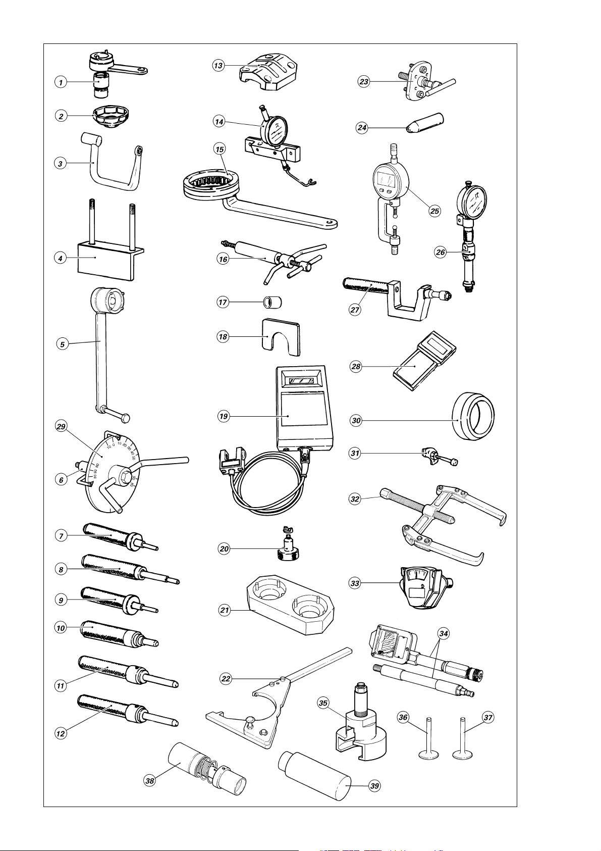
ATTREZZI SPECIALI
1) 88713.1932 Chiave ferma pulegge distribuzione
2) 0675.03.210 Chiave smontaggio cartuccia olio
3) 88713.1139 Chiave per serraggio dadi testa
4) 88713.0891 Base per montaggio testa
5) 88713.0137 Chiave ferma ingranaggio coppia primaria
6) 88713.0123 Attrezzo porta disco graduato per controllo anticipo con disco
7) 88713.0874 Punzone piantaggio guidavalvola scarico
8) 88713.0879 Punzone estrazione guidavalvola
9) 88713.1933 Punzone piantaggio guidavalvola aspirazione
10) 88700.5608 Punzone per piantaggio paraolio
11) 88713.1934 Punzone per piantaggio sede valvola scarico
12) 88713.1935 Punzone per piantaggio sede valvola aspirazione
13) 88765.1033 Attrezzo misura profondità sacche valvole
14) 88765.1001 Calibro alzata valvola
15) 88713.0146 Chiave ferma tamburo frizione
16) 88713.0862 Estrattore perno bilancieri
17) 713.1.117.1A Bussola per calibro tensione cinghia
18) 88713.1309 Spessimetro a forchetta 2,35 mm
19) 041.1.014.1A Frequenzimetro CLAVIS BELT TENSION METER-TYPE
20) 88765.0978 Calibro per controllo registri semianelli
21) 88713.1936 Attrezzo fase albero a camme
22) 88731.1901 Chiave ferma alternatore per bloccaggio dado
23) 88713.1435 Estrattore per smontare coperchio alternatore
24) 88700.5749 Cappuccio assemblaggio semicarter
25) 88713.1781 Micrometro serraggio bielle
26) 88765.0968 Calibro controllo P.M.S.
27) 88713.1429 Attrezzo per piantaggio paraolio valvole
28) 88765.1068 Strumento di diagnosi
88765.1069 Strumento di diagnosi
88765.1070 Strumento di diagnosi
88765.1071 Strumento di diagnosi
88765.1072 Strumento di diagnosi
I
GB
F
D
E
29) 98112.0002 Disco graduato
30) 88700.5665 Bussola montaggio ingranaggio campana frizione
31) 88713.1091 Piastrino per posizionamento forcella innesto marce
32) USAG 454/4 Estrattore volano
33) 88765.0999 Calibro tensione cinghia
34) 88765.1140 Apparecchiatura prova compressione (MOTOMETER)
35) 88713.1502 Estrattore pignone coppia primaria
36) 88765.1187 Valvola calibro aspirazione
37) 88765.1186 Valvola calibro scarico
38) 88713.1968 Attrezzo montaggio tenuta pompa acqua
39 88713.1967 Attrezzo montaggio controfaccia
Scomposizione motore / Engine disassembly 23
Page 24

SPECIAL SERVICE TOOLS FOR ENGINE
1) 88713.1932 Timing belt rollers wrench
2) 0675.03.210 Wrench for removing oil filter cartridge
3) 88713.1139 Wrench for tightening head nuts
4) 88713.0891 Base for head assemby
5) 88713.0137 Primary drive gear lock wrench
6) 88713.0123 Degree wheel holder tool for ignition advance check
7) 88713.0874 Exhaust valve guide drift
8) 88713.0879 Valve guide pulling drift
9) 88713.1933 Intake valve guide drift
10) 88700.5608 Oil seal drift
11) 88713.1934 Exhaust valve seat drift
12) 88713.1935 Intake valve seat drift
13) 88765.1033 Valve pocket depth gauge
14) 88765.1001 Valve lift gauge
15) 88713.0146 Clutch drum lock wrench
16) 88713.0862 Rocker shaft puller
17) 713.1.117.1A Bushing for belt tension gauge
18) 88713.1309 Fork feeler gauge - 2.35 mm
19) 041.1.014.1A Frequency meter CLAVIS BELT TENSION METER-TYPE
20) 88765.0978 Split ring shim gauge
21) 88713.1936 Camshaft timing tool
22) 88713.1901 Generator clamp wrench for nut locking
23) 88713.1435 Puller for removal of generator cover
24) 88700.5749 Casing assembly cap
25) 88713.1781 Micrometer for tightening con-rods
26) 88765.0968 TDC check gauge
27) 88713.1429 Valve seal drift
28) 88765.1068 Tester
88765.1069 Tester
88765.1070 Tester
88765.1071 Tester
88765.1072 Tester
I
E
F
D
E
29) 98112.0002 Degree wheel
30) 88700.5665 Bushing for mounting clutch housing gear
31) 88713.1091 Plate for positioning gear engagement fork
32) USAG 454/4 Flywheel puller
33) 88765.0999 Belt tension gauge
34) 88765.1140 Compression tester (MOTOMETER)
35) 88713.1502 Primary drive sprocket puller
36) 88765.1187 Master intake valve
37) 88765.1186 Master exhaust valve
38) 88713.1968 Water pump seal assembly tool
39) 88713.1967 Counter face assembly tool
24 Scomposizione motore / Engine disassembly
Page 25
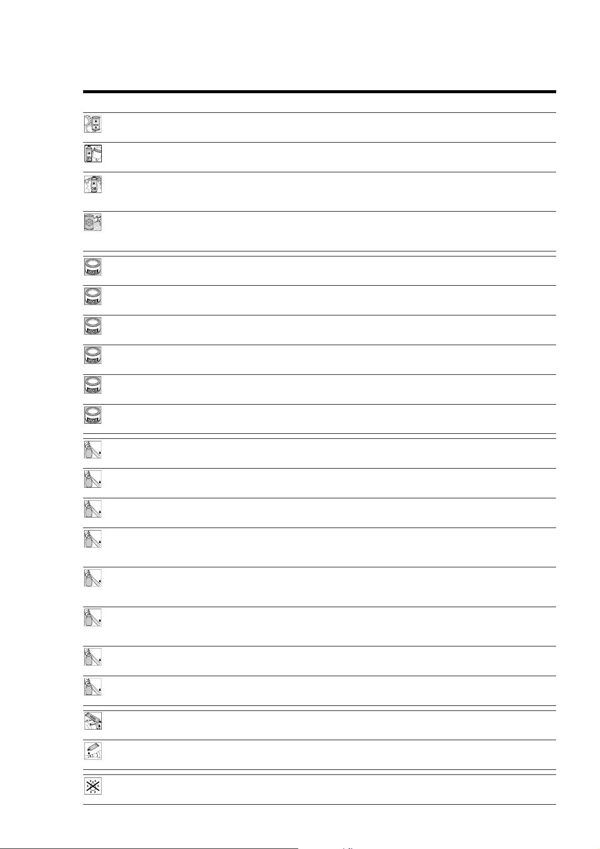
CARATTERISTICHE PRODOTTI
I prodotti usati per il serraggio, la sigillatura e la lubrificazione degli elementi verranno rappresentati all'interno della
figura con un simbolo. La tabella riporta i simboli utilizzati e le caratteristiche relative ai vari prodotti.
Simbolo Caratteristiche Prodotto consigliato
Olio motore SHELL
Liquido speciale per sistemi idraulici DOT 4. SHELL
Olio per ingranaggi SAE 80-90 o prodotti specifici per catene SHELL
con anelli OR. Advance Chain o
Liquido antigelo (totalmente assente da nitriti, ammine e fosfati) SHELL
35÷40% + acqua. Advance coolant o
GREASE A Grasso a base di litio, a fibra media, di tipo "multipurpose". SHELL Alvania R3
A
GREASE B Grasso al bisolfuro di molibdeno resistente ad estreme sollecitazioni SHELL
B
C
D
E
F
meccaniche e termiche. Retinax HDX2
GREASE C Grasso per cuscinetti e articolazioni sottoposti a prolungate sollecitazioni SHELL
GREASE D Grasso con proprietà protettive, anticorrosive e di idrorepellenza. SHELL
GREASE E Grasso PANKL - PLB 05.
GREASE F Grasso OPTIMOL - PASTE WHITE T.
meccaniche. Temperatura di utilizzo da –10 a 110
°
C. Retinax LX2
Advance Ultra 4
Advance Brake DOT 4
Advance Teflon Chain
Glycoshell
Retinax HD2
LOCK 1 Frenafiletti a debole resistenza meccanica. LOCTITE 222
1
LOCK
LOCK 2 Frenafiletti a media resistenza meccanica. LOCTITE 243
2
LOCK
LOCK 3 Frenafiletti ad alta resistenza meccanica per sigillatura di parti filettate. LOCTITE 270
3
LOCK
LOCK 4 Sigillante per piani ad alta resistenza meccanica e ai solventi. Resiste ad LOCTITE 510
4
LOCK
LOCK 5 Adesivo strutturale permanente per accoppiamenti cilindri a LOCTITE 128443
5
LOCK
LOCK 6 Sigillante di tubazioni e raccorderie medio-grandi, per acqua e ogni tipo LOCTITE 577
6
LOCK
LOCK 7 Adesivo istantaneo gomma - plastica, con base etilica caricato LOCTITE 480
7
LOCK
LOCK 8 Bloccante permanente di parti filettate, cuscinetti, bussole, scanalati LOCTITE 601
8
LOCK
alte temperature (fino a 200 °C), sigilla pressioni fino a 350 Atm e
colma giochi fino a 0,4 mm.
scorrimento libero o filettati su parti meccaniche. Alta resistenza
meccanica ed ai solventi. Temperatura di utilizzo da –55 a 175
di gas (ad eccezione dell'ossigeno). Massima capacità di riempimento:
0,40 mm (gioco diametrale).
ad elastomeri.
e chiavette. Temperatura di esercizio da –55 a 150 °C.
Guarnizione liquida THREE BOND.
°
C.
Pasta sigillante per tubi di scarico. Autosigillante si indurisce al calore FIRE GUM HOLTS
e resiste a temperature superiori a 1000
Spray impiegato nel trattamento degli impianti elettrici. Rimuove umidità SHELL
e condensa e offre alta resistenza alla corrosione. Idrorepellente. Advance Contact Cleaner
°
C.
Scomposizione motore / Engine disassembly 25
Page 26
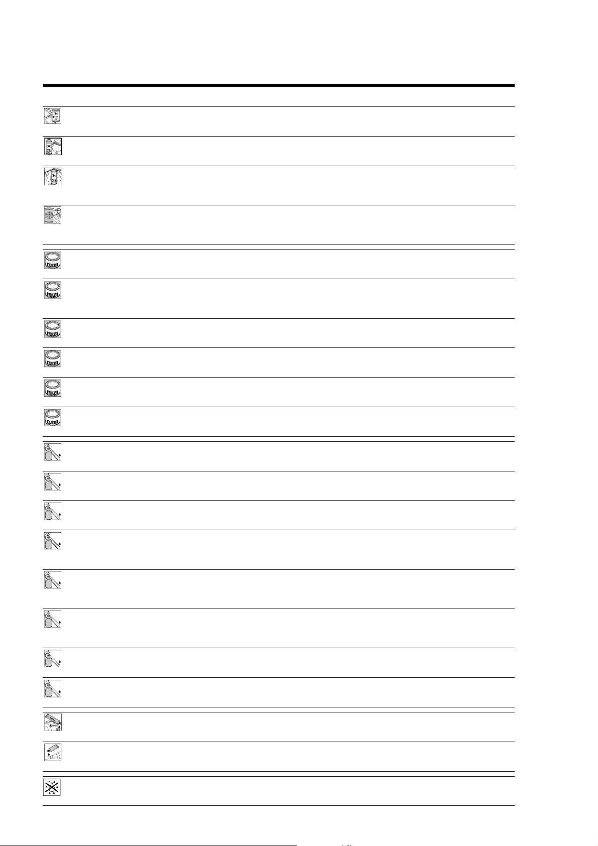
PRODUCT SPECIFICATIONS
Symbols inside the diagram show the type of threadlocker, sealant or lubricants to be used at the points indicated. The
table below shows the symbols together with the specifications for the threadlockers, sealants and lubricants to be used.
Symbol Specifications Advised product
Engine oil SHELL
DOT 4 special hydraulic brake fluid. SHELL
SAE 80-90 gear oil or special products for chains with O-rings. SHELL
Anti-freeze (nitride, amine and phosphate free) 35 -40% SHELL
water solution. Advance coolant or
GREASE A Multipurpose, medium fibre, lithium grease. SHELL Alvania R3
A
GREASE B Molybdenum disulphide grease, high mechanical stress and high SHELL Retinax HDX2
B
GREASE C Bearing/joint grease for parts subject to prolonged mechanical stress. SHELL Retinax HDX2
C
GREASE D Protective grease. Corrosion protectant, waterproof. SHELL Retinax HDX2
D
GREASE E PANKL grease PLB 05.
E
temperature resistant.
Temperature range: -10 to 110
°
C.
Advance Ultra 4
Advance Brake DOT 4
Advance Chain or
Advance Teflon Chain
Glycoshell
GREASE F OPTIMOL grease PASTE WHITE T.
F
LOCK 1 Low-strength threadlocker. LOCTITE 222
1
LOCK
LOCK 2 Medium-strength threadlocker. LOCTITE 243
2
LOCK
LOCK 3 High-strength thread sealant for threaded parts. LOCTITE 270
3
LOCK
LOCK 4 Flange sealant. Resistant to high mechanical stress, solvents and high LOCTITE 510
4
LOCK
LOCK 5 Permanent adhesive for smooth or threaded cylindrical fasteners on LOCTITE 128443
5
LOCK
LOCK 6 Pipe sealant for pipes and medium to large fasteners. For water and LOCTITE 577
6
LOCK
LOCK 7 Speed bonder for rubber and plastics. Elastomer loaded ethylic base. LOCTITE 480
7
LOCK
LOCK 8 High-strength retaining compound for threaded parts, bearings, bushes, LOCTITE 601
8
LOCK
temperatures (up to 200°C). For pressures up to 350 Atm.
Fills gaps up to 0.4 mm.
mechanical parts. High resistance to mechanical stresses and solvents.
Temperature range: -55 to 175
gases (except oxygen).
Maximum filling capacity: diameter gaps up to 0.40 mm.
splines and keys. Temperature range: -55 to 150°C.
°
C.
THREE BOND liquid gasket.
Exhaust pipe paste. Self-curing sealant, hardens when heated. FIRE GUM HOLTS
For temperatures over 1000
Spray used in treating electrical systems to eliminate moisture and SHELL
condensation. Provides high resistance to corrosion. Waterproof. Advance Contact cleaner.
26 Scomposizione motore / Engine disassembly
°
C.
Page 27
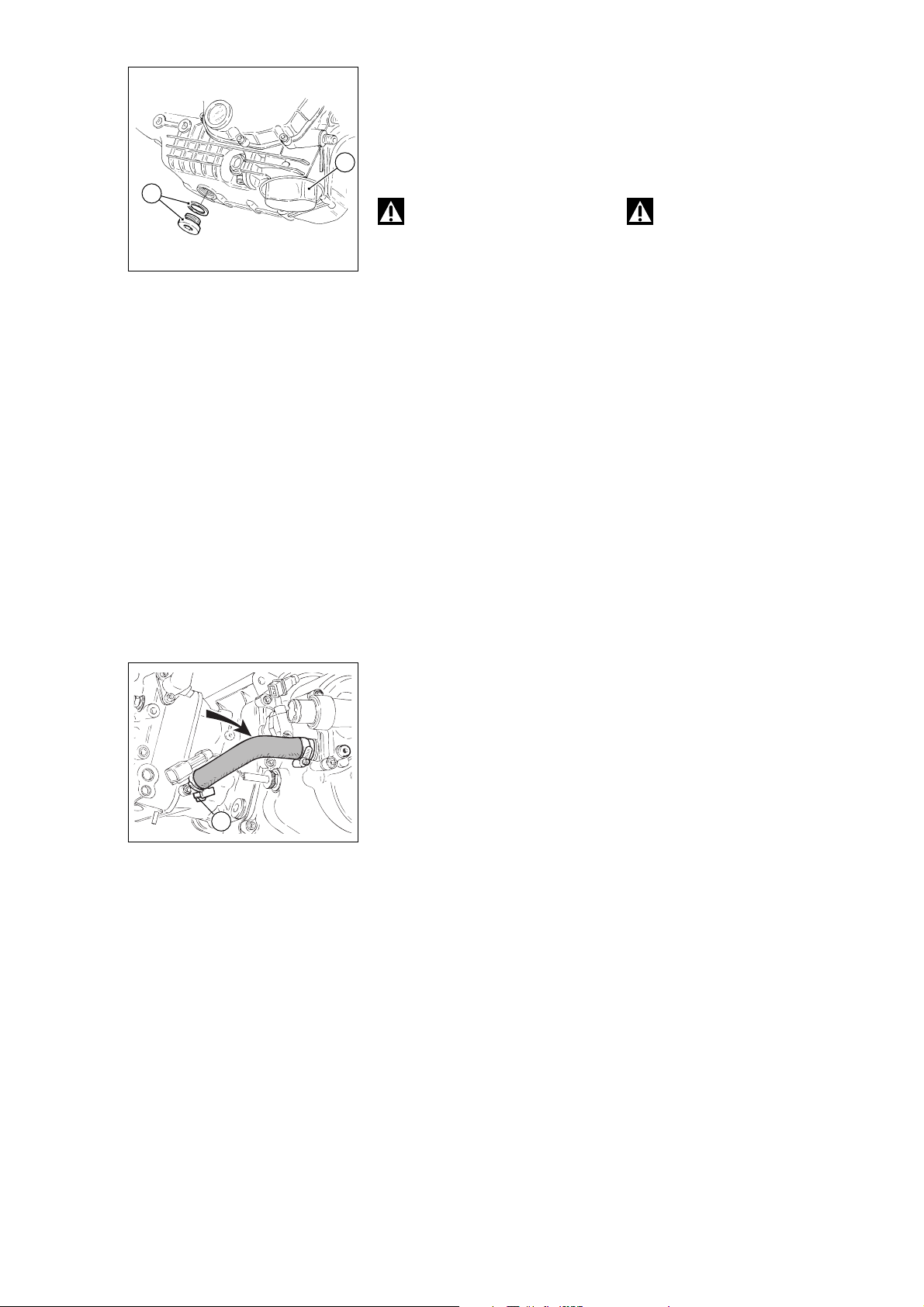
SCARICO OLIO
❍
Svitare e rimuovere il tappo di
scarico (1) con relativa guarnizione.
❍
Svitare e rimuovere il filtro olio (2)
utilizzando l’apposito attrezzo
2
cod.␣ 0675.03.210.
1
Attenzione
Non disperdere l’olio esausto
nell’ambiente
DRAINING THE OIL
❍
Unscrew and remove the drain
plug (1) complete with its seal.
❍
Unscrew and remove the oil filter
(2) using the service tool part
no.␣ 0675.03.210.
Warning
Dispose of oil in compliance
with environmental protection
regulations.
SCARICO LIQUIDO DI
DRAINING THE COOLANT
RAFFREDDAMENTO
❍
Unscrew the screw (1) of the
❍
Svitare la vite (1) dal raccordo di
mandata acqua dalla pompa al
cilindro orizzontale e lasciare drenare
il liquido contenuto nel motore.
❍
Rimuovere i manicotti di
coolant delivery hose between the
pump and the horizontal cylinder and
allow the engine coolant to drain off.
❍
Remove the hoses between the
pump and the cylinders.
collegamento pompa-cilindri.
1
Scomposizione motore / Engine disassembly 27
Page 28
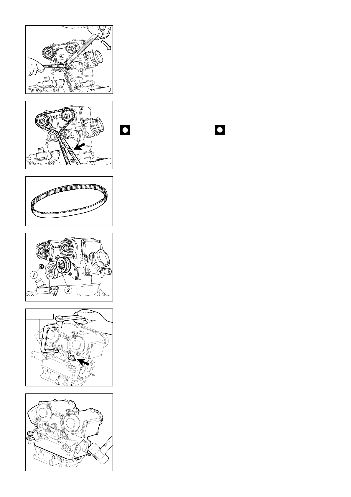
CANDELE, CINGHIE E
TENDITORI MOBILI
❍
Rimuovere le candele di
accensione.
- Allentare e rimuovere il dado di
fissaggio (1) e sfilare
contemporaneamente il tenditore
mobile e la cinghia.
●
In caso di riutilizzo, praticare sulla
superficie esterna di ogni cinghia una
freccia indicante il senso di rotazione
(antiorario) ed un riferimento
indicante la testa sulla quale è
montata (“V” o “O”).
SPARK PLUGS, TIMING BELTS
AND MOBILE TENSIONERS
❍
Remove the spark plugs.
- Loosen and remove the retaining
nut (1). Remove the mobile
tensioner roller and the belt.
●
If you intend using the belts again
after disassembly, mark the outer
face of each belt with an arrow
indicating the direction of travel (anticlockwise) and a letter indicating the
head on which the belt is to be
reassembled (e.g. “V” for vertical or
“O” for horizontal).
Importante
Piegature brusche (raggio
minimo di curvatura 20 mm), olio,
benzina o solventi danneggiano
irreparabilmente le cinghie dentate.
Caution
Tight bends (minimum radius
20 mm), oil, fuel or solvents cause
permanent damage to the toothed
belts.
88713.1139
❍
Dopo aver rimosso la tubazione
mandata olio alle teste, svitando le
viti speciali di fissaggio raccordo,
allentare, procedendo in diagonale, i
dadi della testa utilizzando la chiave
cod. 88713.1139 abbinata ad una
chiave a cricchetto.
TESTA
❍
Sfilare leggermente la testa : per
ottenerne il distacco dal cilindro è
necessario assestare qualche colpo
di martello in plastica senza
danneggiarla
❍
Rimuovere i dadi e le rosette
speciali.
❍
Sfilare la testa dai prigionieri.
28 Scomposizione motore / Engine disassembly
CYLINDER HEAD
❍
Remove the pipe delivering oil to
cylinder heads, then undo the special
screws securing the pipe fitting and
loosen the cylinder head nuts using
service tool part no.␣ 88713.1139 and
a ratchet handle; work diagonally.
❍
Lift the head up slightly. Tap the
head with a plastic hammer to
release it from its position.
❍
Remove the nuts and the special
spring washers.
❍
Remove the head from the stud
bolts.
Page 29
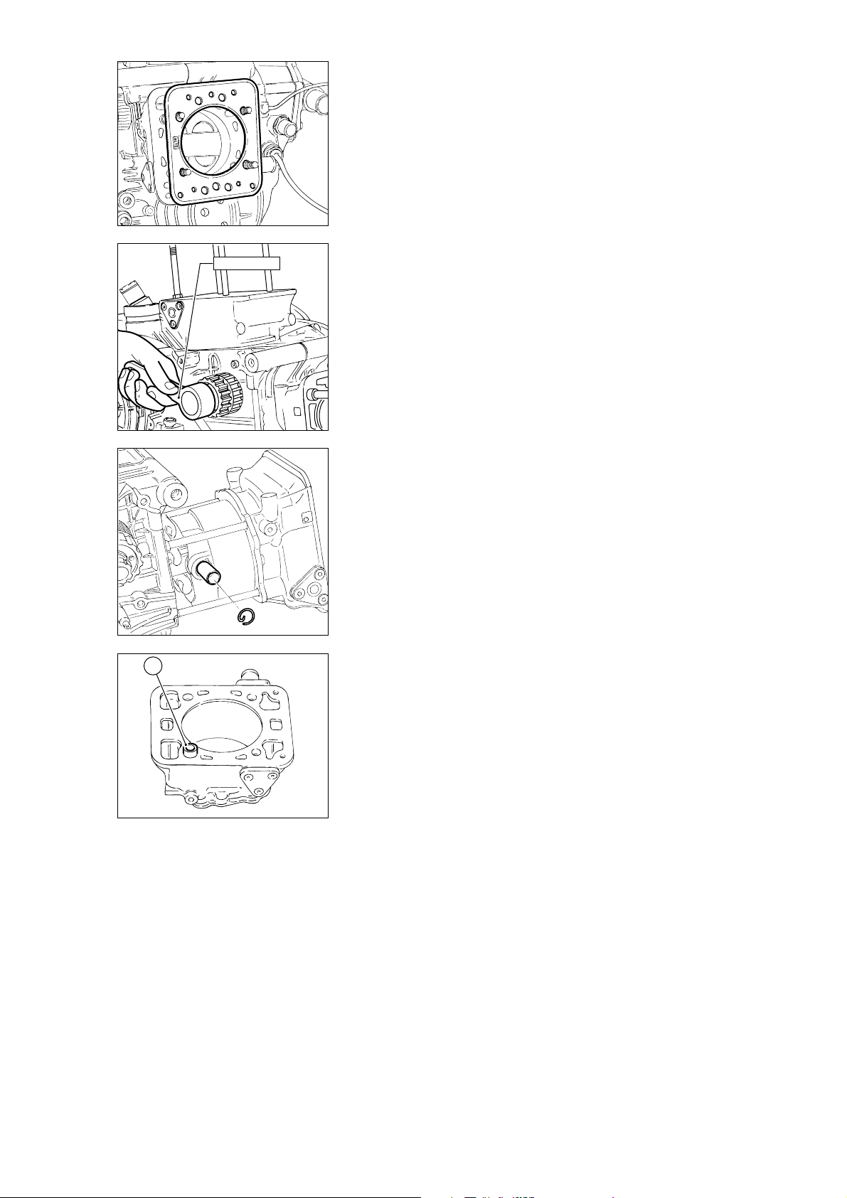
CILINDRO E PISTONE
❍
Sfilare la guarnizione di tenuta tra
testa e cilindro. La guarnizione
metallica è riutilizzabile perciò è
necessario contrassegnarla per
installarla nello stesso gruppo
termico durante il rimontaggio.
- Portare il pistone del cilindro
orizzontale al punto morto superiore
ruotando le pulegge sull’albero di
rinvio distribuzione con la chiave cod.
88713.1932. I perni della chiave
88713.1932
devono essere inseriti nei 2 fori non
filettati della puleggia.
❍
Sfilare delicatamente il cilindro; se
necessario scuoterlo leggermente
con qualche colpo di martello in
gomma quindi sollevarlo fino a che
risulti accessibile lo spinotto del
pistone.
❍
Rimuovere il fermo dello spinotto
dal lato frizione.
- Operando dal lato opposto, sfilare
lo spinotto quel tanto che basta da
disimpegnare la biella.
❍
Sfilare completamente dai
prigionieri il gruppo completo
pistone-cilindro. In caso di rimozione
del pistone dal cilindro
contrassegnare gli elementi per
poterli accoppiare nel rimontaggio.
- Portare il pistone del cilindro
verticale al punto morto superiore ed
agire analogamente al cilindro
orizzontale.
❍
Rimuovere dai cilindri le boccole
(1) di centraggio.
- A questo punto è consigliabile
otturare le aperture del carter con
1
uno straccio per impedire che corpi
CYLINDERS AND PISTONS
❍
Remove the gasket between the
head and the cylinder. This is a metal
gasket and can be used again at
reassembly. If you intend using the
gasket again, mark it so that it can
be refitted to the same cylinder at
reassembly.
- Move the horizontal cylinder piston
to the top dead centre position by
turning the rollers of the timing
layshaft with the special tool part no.
88713.1932. Insert the spanner pins
in the two unthreaded holes in the
roller; do not use the threaded holes.
❍
Carefully lift the cylinder. If
necessary, tap the cylinder lightly
with a rubber hammer. Raise the
cylinder until the piston gudgeon pin
is accessible.
❍
Remove the circlip from the
gudgeon pin on the clutch-side.
- Working from the other side, move
the gudgeon pin out until the con-rod
is released.
❍
Lift the piston-cylinder assembly
and remove from the stud bolts. If
you are going to remove the piston
from the cylinder, mark all the parts
accordingly so that they can be
matched at reassembly.
- Move the piston of the vertical
cylinder to top dead centre and then
proceed as per the instructions
above for the horizontal cylinder.
❍
Remove the centring bushes (1)
from the cylinders.
- Block the openings in the
crankcase with rags to prevent
anything falling inside.
estranei possano cadere all’interno.
Scomposizione motore / Engine disassembly 29
Page 30
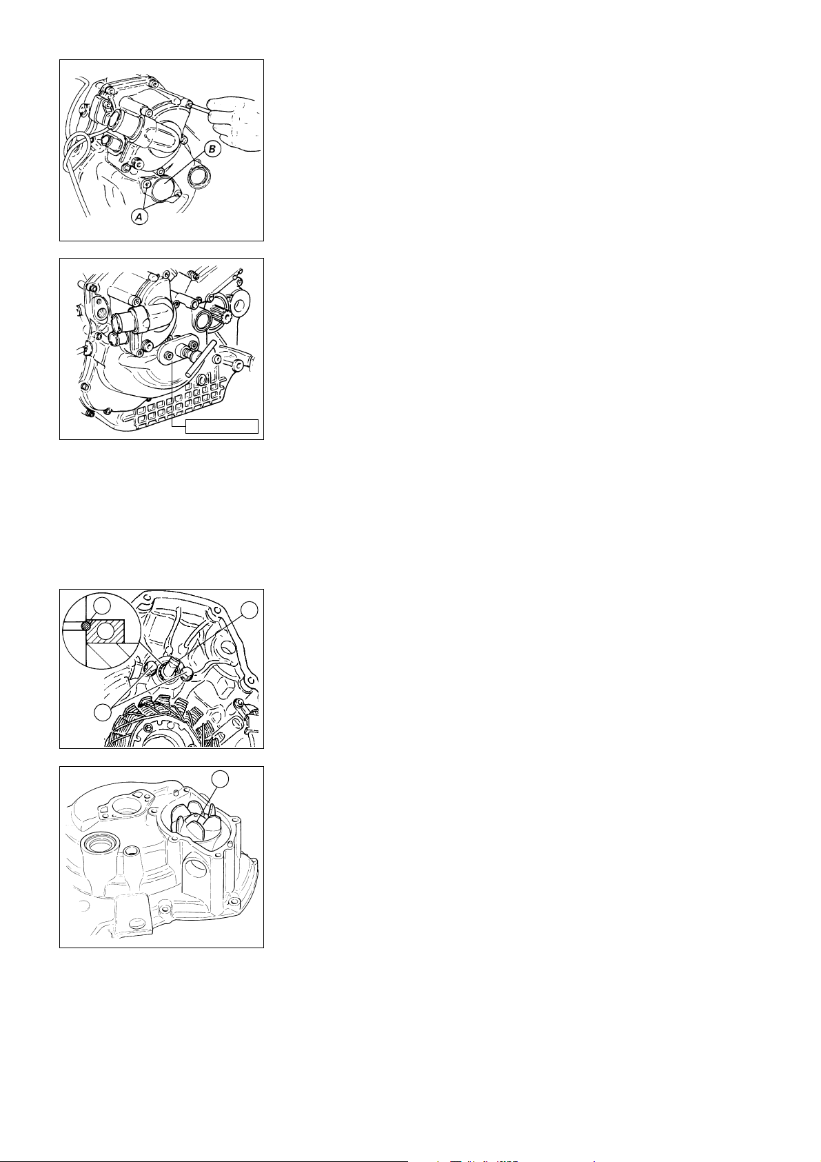
88713.1435
COPERCHIO ALTERNATORE
❍
Svitare le 2 viti (A) che fissano il
coperchietto (B) di chiusura del foro
in corrispondenza dell’albero motore.
- Rimuovere il coperchietto (B).
- Svitare le viti di fissaggio del
coperchio alternatore. Vincolato a
questo coperchio si trovano lo
statore del generatore, il sensore
numero di giri e fase e il gruppo
pompa acqua.
❍
Fissare l’estrattore cod.
88713.1435 nei fori delle viti (A) di
fissaggio del coperchietto
precedentemente rimosso.
- Ruotare lentamente il perno
centrale dell’attrezzo fino ad ottenere
il distacco del coperchio dal
semicarter alternatore.
GENERATOR COVER
❍
Unscrew the 2 bolts (A) fixing the
small cover (B) to the hole over the
crankshaft.
- Remove the cover (B).
- Unscrew the retaining screws from
the generator cover. The generator
cover houses the generator stator,
the rpm and timing sensors and the
water pump unit.
❍
Fix the puller part no. 88713.1435
to the holes (A) for the small cover
screws removed previously.
- Slowly turn the centre pin of the
puller to detach the cover from the
generator cover.
1
3
meccanica o i cuscinetti di
2
supporto della girante utilizzare la
seguente procedura:
– premere la girante mandando a
pacco la molla;
– mandare in battuta il distanziale (3)
in modo da poter sfilare l'anello
– Dovendo sostituire la tenuta
A
elastico di bloccaggio (1)
– sfilare anche il distanziale (3)
– svitare e rimuovere le due viti (A)
con rosetta
4
– sfilare la girante (4) con anello di
tenuta dal lato esterno.
– To change the mechanical seal or
the rotor bearings, proceed as
follows:
– press the rotor so to fully
compress the spring;
– push the spacer (3) fully home
and remove the snap ring (1);
– remove the spacer (3);
– remove the two screws (A) and
washers;
– take out the rotor (4) and seal
form the outside.
30 Scomposizione motore / Engine disassembly
Page 31
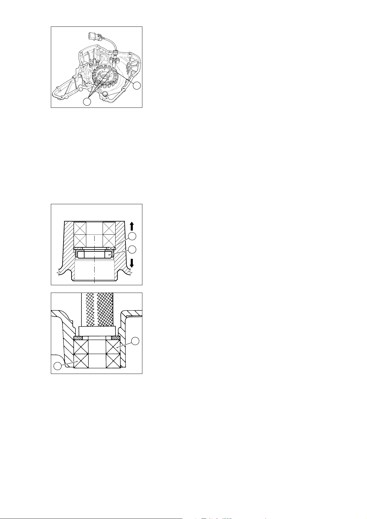
❍
❍
Rimuovere lo statore (8) del
generatore dal suo fissaggio
all’interno del coperchio svitando le 3
To remove the generator stator (8)
from its seat inside the cover,
unscrew the 3 screws (9).
viti (9).
8
9
❍
Sfilare la controfaccia (6)
dell'anello di tenuta.
❍
Scaldare il coperchio alternatore
fino alla temperatura di 150
❍
7
6
Procedere all'estrazione dei due
cuscinetti (3 - 4) e del distanziale (7),
operando dal lato girante, spingendo
sul distanziale (7) mediante un
°
C
❍
Remove the counter face (6) of
the seal ring.
❍
Heat up the generator cover up to
150
°
C.
❍
Remove the two bearings (3-4)
and the spacer (7) from the rotor
side and push against the spacer (7)
using a suitable drift (bushing).
punzone adatto (bussola).
4
3
Scomposizione motore / Engine disassembly 31
Page 32
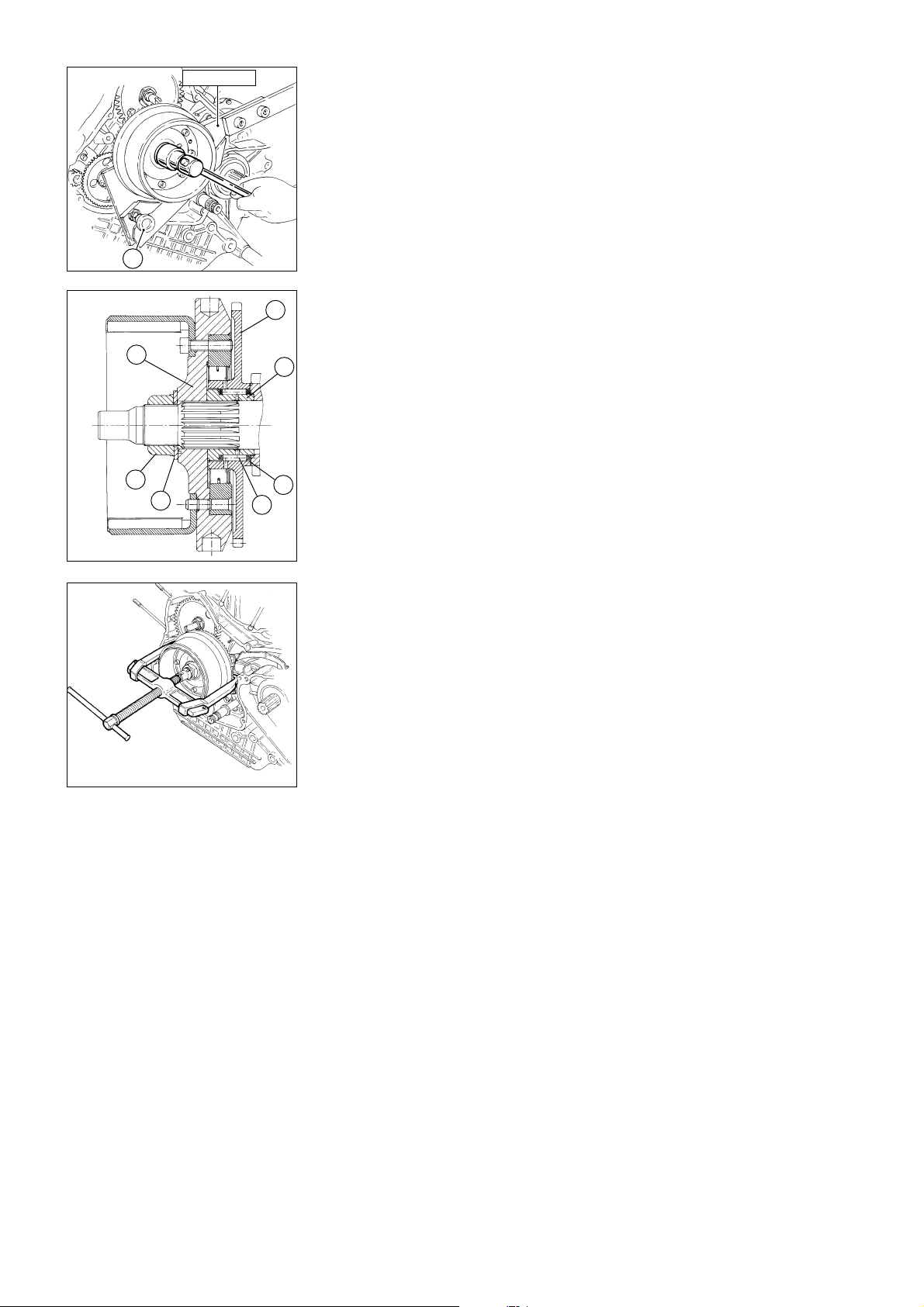
88713.1901
ALTERNATORE E VOLANO
▲
Montare sul volano l’attrezzo cod.
88713.1901 inserendone i denti nei
due fori diametrali, verificarne la
corretta chiusura tramite il perno di
fermo (A), e bloccarne la rotazione
appoggiando opportunatamente
l’impugnatura alla struttura di
sostegno del motore.
❍
Svitare il dado (1) di fissaggio del
A
rotore ruotandolo in senso antiorario.
Per poter eseguire correttamente
questa operazione è necessario
disporre di una chiave a bussola con
4
braccio sufficientemente lungo,
inoltre, mentre si svita, spingere
3
assialmente la bussola per evitare
dannosi contraccolpi in caso di
5
fuoriuscita della bussola dal dado.
❍
Rimuovere il dado (1), la molla a
tazza (2).
La rimozione del volano (3) richiede
l'impiego dell'estrattore
USAG 454/4.
1
2
6
Assicurare che i bracci
7
dell'estrattore siano ben posizionati,
e che il perno filettato insista
sull'albero motore.
Estrarre il volano avvitando il perno
filettato.
GENERATOR AND FLYWHEEL
▲
Fit the service tool part no.
88713.1901 to the flywheel so that
the teeth are properly inserted in the
two holes. Make sure of proper
fitting by checking the lock pin (A)
and rest the handle on the engine
support frame to clamp the tool.
❍
Unscrew the rotor retaining nut (1)
anti-clockwise. To unscrew the nut,
use a box spanner with a long
tommy bar. As you unscrew, press
axially down on the box spanner to
prevent the spanner slipping off the
nut and damaging components.
❍
Remove the nut (1) and the
Belleville washer (2).
Use puller USAG 454/4 to remove
the flywheel (3).
Make sure of puller arms proper
positioning and check that the
threaded pin is resting on the
crankshaft.
Tighten the threaded pin to remove
the flywheel.
Once the flywheel has been
removed, remove the driven gear (4),
the double-diameter spacer (5) with
the roller bearing (6) and the washer
(7).
Una volta estratto il volano
rimuovere l'ingranaggio condotto
dell'avviamento (4), il distanziale a
doppio diametro (5) con il relativo
cuscinetto a rulli (6) e la rosetta (7).
32 Scomposizione motore / Engine disassembly
Page 33
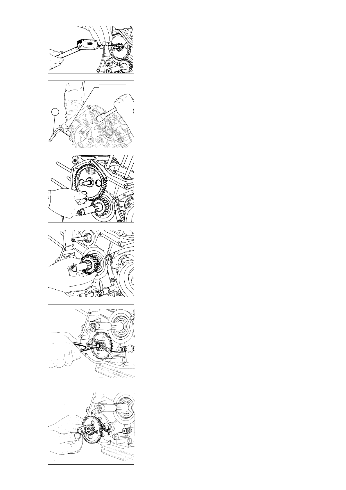
INGRANAGGI COMANDO
TIMING GEARS
DISTRIBUZIONE
- Straighten the lock washer of the
- Raddrizzare la rondella di sicurezza
del dado di bloccaggio ingranaggio
condotto distribuzione.
- Montare nei 2 fori non filettati della
puleggia esterna sull’albero rinvio
distribuzione la chiave
cod.␣ 88713.1932 e bloccarne la
88713.1932
rotazione inserendo un perno (A) nel
foro dell’impugnatura della chiave e
nella sede della vite di fissaggio
anteriore blocco motore al telaio.
A
❍
Svitare il dado di fissaggio
ingranaggio condotto ruotandolo in
senso antiorario con una chiave
adatta.
❍
Rimuovere il dado, la rondella ,
timing gear securing nut.
- Fit the service tool part no.
88713.1932 to the two unthreaded
holes in the outer roller on the timing
layshaft. Insert a pin (A) through the
hole in the tool handle and into the
front engine-frame mounting bolt
hole to clamp the roller in position.
❍
Unscrew the retaining nut of the
driven gear by turning it anticlockwise with a suitable tool.
❍
Remove the nut, the washer the
driven gear and the key.
❍
Remove the timing drive gear and
its key from the crankshaft.
l’ingranaggio condotto della
distribuzione e la linguetta.
❍
Sfilare dall’albero motore
l’ingranaggio di comando
distribuzione e la relativa linguetta.
Gruppo avviamento
❍
Rimuovere l’anello di arresto per il
fissaggio del gruppo ingranaggio
ozioso del dispositivo di avviamento.
❍
Rimuovere il gruppo ingranaggio
ozioso del dispositivo di avviamento
e relativi rasamenti.
❍
Verificare visivamente il grado di
usura dell'ingranaggio e del relativo
albero.
Scomposizione motore / Engine disassembly 33
Starting assembly
❍
Remove stop ring for idle gear
assembly of starting device.
❍
Remove idle gear assembly of
starting device and all shims.
❍
Visually check wear degree of
gear and shaft.
Page 34
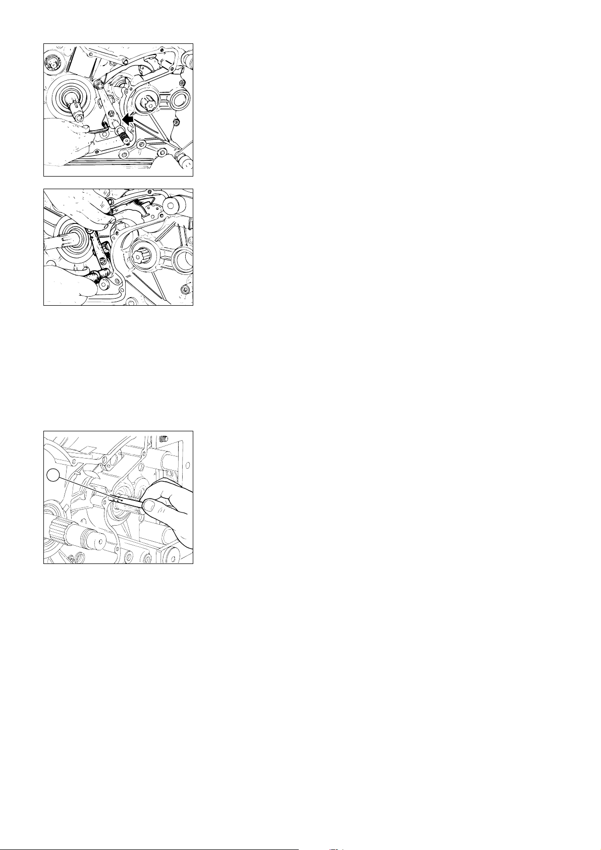
LEVERAGGIO SELEZIONE
MARCE
❍
Svitare le 2 viti di fissaggio del
leveraggio di selezione del cambio.
❍
Rimuovere il leveraggio completo
dal carter.
GEAR SELECTOR LEVER
❍
Unscrew the 2 retaining bolts
from the gear selector lever.
❍
Remove the complete lever
assembly from the casing.
ASTA COMANDO FRIZIONE
❍
Sfilare l’asta (1) comando frizione
completa di anelli OR.
1
CLUTCH PUSHROD
❍
Slide out the clutch pushrod (1)
complete with O-rings.
34 Scomposizione motore / Engine disassembly
Page 35
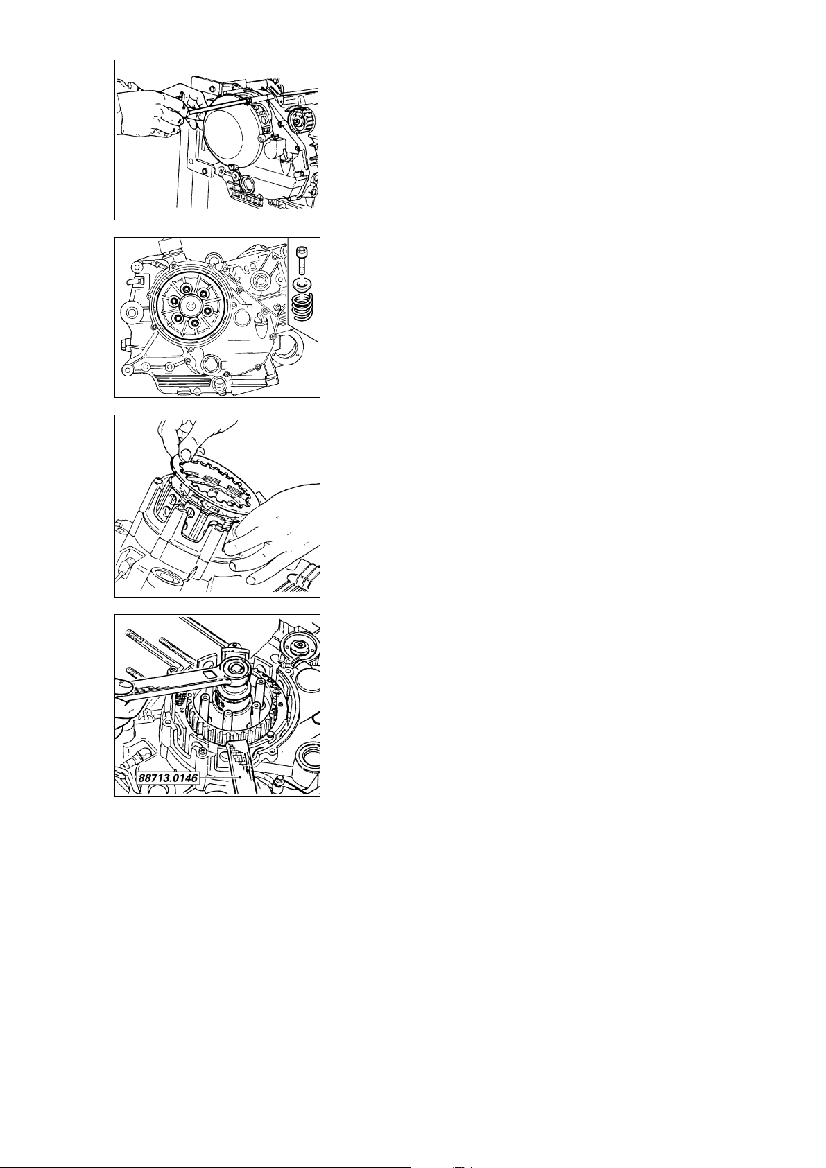
FRIZIONE
❍
Svitare le 4 viti di fissaggio del
coperchio di ispezione frizione e
rimuoverlo.
❍
Svitare e rimuovere le 6 viti di
fissaggio del pacco frizione e sfilare
le molle.
- Sfilare lo spingidisco e i dischi della
frizione.
- Raddrizzare la rosetta di sicurezza
del dado di bloccaggio tamburo
frizione.
▲
Montare sul tamburo l’attrezzo
cod. 88713.0146 e bloccarne la
rotazione portando l’impugnatura
dell’attrezzo a contatto con un perno
inserito in uno dei fori di fissaggio
blocco motore al telaio.
- Con una chiave a bussola adatta
svitare il dado di bloccaggio tamburo
frizione.
CLUTCH
❍
Unscrew the 4 retaining screws
on the clutch inspection cover.
Remove the cover.
❍
Unscrew and remove the 6
retaining screws of the clutch plate
set and remove the springs.
- Remove the plate pusher and the
clutch plates.
- Straighten the spring lock washer
on the clutch drum nut.
▲
Fit service tool part no.
88713.0146 to the clutch drum and
clamp the drum in position by
stopping the tool handle against a
pin inserted in one of the engineframe mounting holes.
- Using a socket spanner, unscrew
the clutch drum lock nut.
Scomposizione motore / Engine disassembly 35
Page 36
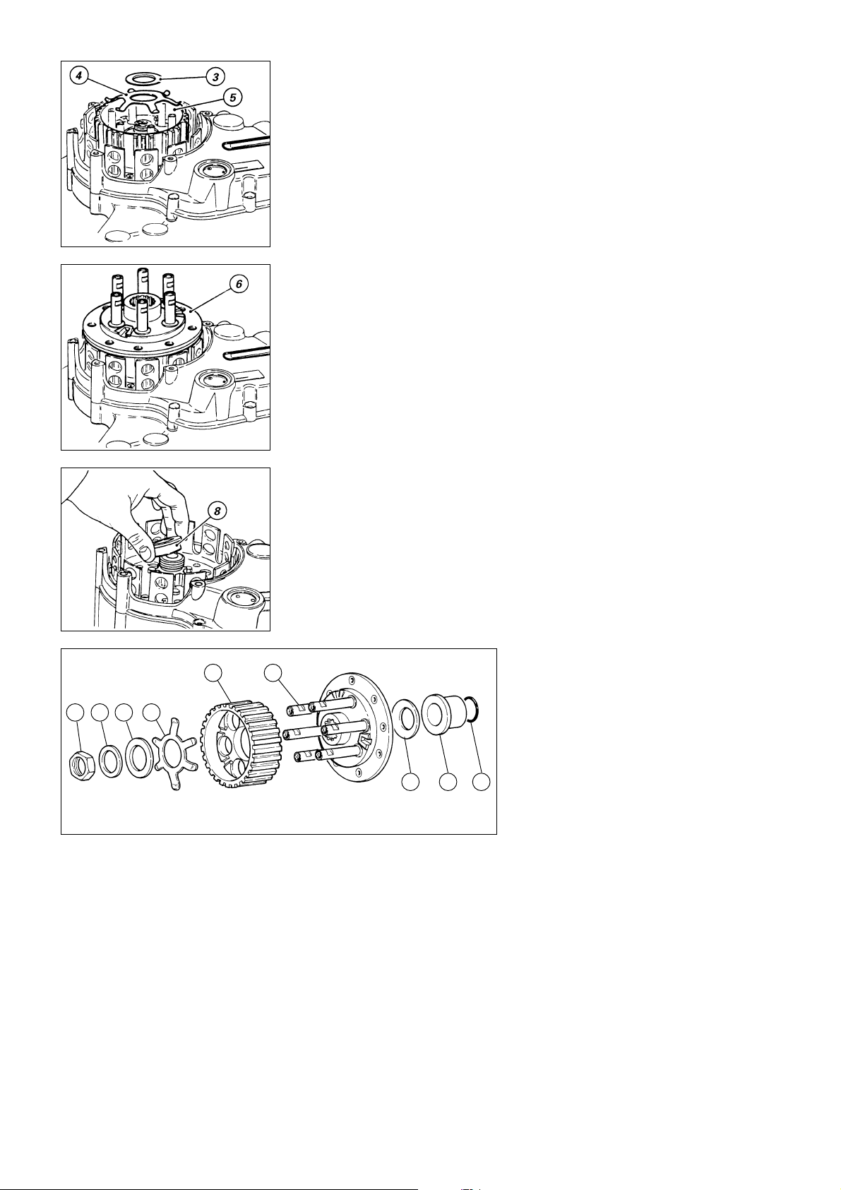
Rimuovere:
- il dado (1)
- la rondella (tenera) (2);
- il distanziale (3);
- la molla antisaltellamento (4);
- il tamburo frizione (5);
- il gruppo flangia (6);
- la molla a tazza (7);
- il distanziale (8) con OR (9).
Remove
- the nut (1);
- the (soft) washer (2);
- the spacer (3);
- the anti-slip spring (4);
- the clutch drum (5);
- the flange assembly (6);
- the Belleville washer (7);
- the spacer (8) with the O-ring (9).
31 2 4
5 6
987
36 Scomposizione motore / Engine disassembly
Page 37
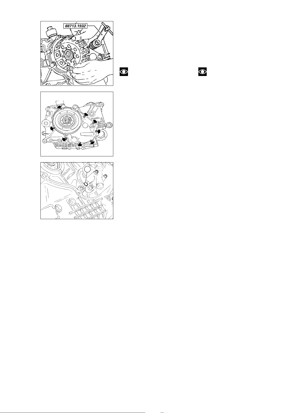
COPERCHIO FRIZIONE
CLUTCH CASING
- Posizionare l'attrezzo
cod.␣ 88713.1932, come in figura, per
impedire la rotazione della campana
durante l'allentamento delle viti.
- Rimuovere la campana frizione
dall’ingranaggio della primaria.
Note
Se non deve essere eseguito
nessun intervento sugli elementi che
compongono il coperchio, questa
operazione può essere evitata
lasciando il gruppo campana e
ingranaggio della primaria montato
- Fit the service tool part no.
88713.1932, as shown to prevent
the drum unit from rotating while the
screws are being loosened.
- Remove the clutch housing from
the primary drive gear.
Note
If you do not intend to work on
any of the clutch casing
components, you may skip the
previous operation and leave the
housing and the primary drive gear
mounted on the clutch casing.
sul coperchio frizione.
- Unscrew and remove the 8
- Svitare e rimuovere le 8 viti di
fissaggio del coperchio frizione e,
aiutandosi con un martello di
plastica, battere in vari punti sul
contorno del coperchio per favorire il
distacco dello stesso dal semicarter.
- Rimuovere l’anello OR (1) in
corrispondenza del passaggio olio tra
retaining bolts on the clutch casing.
Tap around the outside of the casing
with a plastic hammer so that clutch
casing detaches from the crankcase
half.
- Remove the 0-ring (1) from the oil
way between the clutch casing and
the crankcase half.
coperchio frizione e semicarter.
1
Scomposizione motore / Engine disassembly 37
Page 38
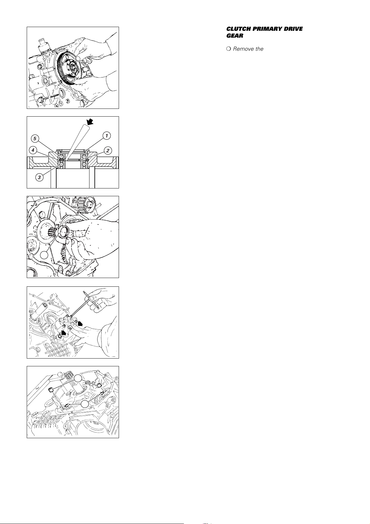
INGRANAGGIO FRIZIONE
,,@@ÀÀ
,,@@ÀÀ
,,yy
DELLA TRASMISSIONE
CLUTCH PRIMARY DRIVE
GEAR
PRIMARIA
❍
Remove the clutch gear complete
❍
Sfilare dall’albero primario
l’ingranaggio completo di cuscinetti e
with bearings and oil seal from the
primary drive shaft.
paraolio.
To change parts inside the gear,
Per la sostituzione degli elementi
interni all’ingranaggio operare come
segue:
- Rimuovere il paraolio (1)
dall’ingranaggio.
- Con un piccolo punzone scostare il
distanziale (2) interno ai due
cuscinetti.
5
4
1
2
- Con un punzone adatto, appoggiato
all’anello interno del cuscinetto (3),
spingere quest’ultimo verso
l’esterno cambiando continuamente
punto di appoggio per ottenere
un’estrazione in squadro del
3
cuscinetto.
❍
Rimuovere il distanziale interno (2)
e l’anello seeger speciale (4): questi
elementi vanno sempre sostituiti in
coppia
❍
Rimuovere l’altro cuscinetto (5)
proceed as follows:
- Remove the oil seal (1) from the
gear.
- Using a small drift, move the
spacer (2) between the two
bearings.
- Using a drift on the inner ring of the
bearing (3) push the bearing
outwards; change the drift position
frequently so that the bearing is
pushed out squarely.
❍
Remove the inner spacer (2) and
the snap ring (4); these two
components must be changed as a
pair.
❍
Remove the other bearing (5)
using a drift on the outer ring.
❍
Remove the spacer (6) from the
primary shaft.
utilizzando un adatto tampone che
appoggi sull’anello esterno.
❍
Sfilare dall’albero primario il
distanziale (6).
6
POMPA OLIO
❍
Svitare e rimuovere le viti di
fissaggio della pompa olio completa.
❍
Rimuovere la pompa olio e sfilare
dal semicarter i due anelli OR (1) e le
2 boccole di centraggio (2).
OIL PUMP
❍
Unscrew and remove the oil
pump retaining bolts.
❍
Remove the oil pump, and slide
out the two O-rings (1) and the two
centring bushes (2) from the
crankcase half.
2
1
38 Scomposizione motore / Engine disassembly
Page 39
INGRANAGGIO ALBERO
MOTORE DELLA
CRANKSHAFT PRIMARY
DRIVE GEAR
TRASMISSIONE PRIMARIA
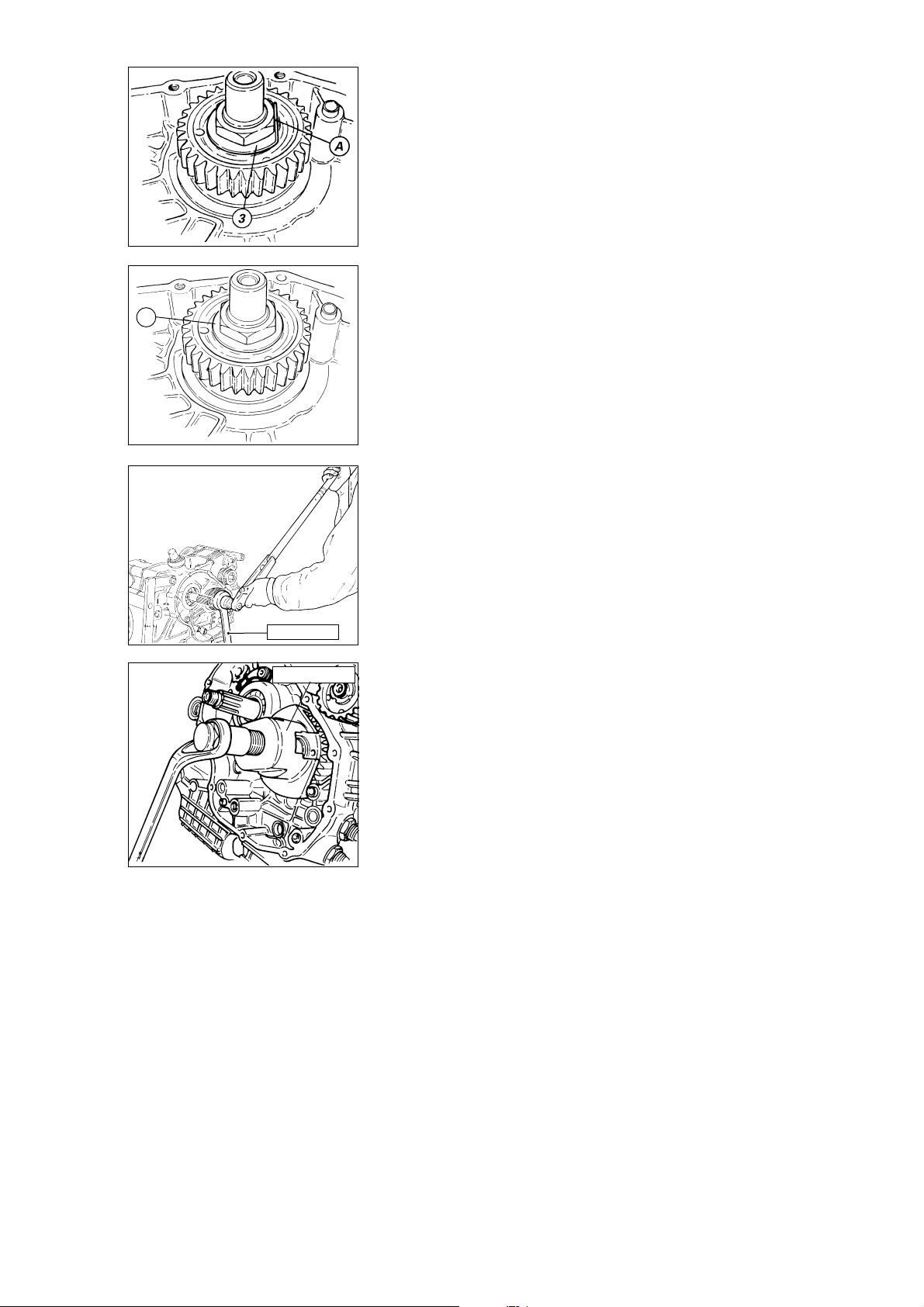
- Straighten the primary drive gear
- Raddrizzare la rosetta (3) di
sicurezza del dado di bloccaggio
ingranaggio abbassando la parte (A)
ribadita sul dado.
▲
Montare sull’ingranaggio l’attrezzo
cod. 88713.0137 e bloccarne la
rotazione inserendo un perno in uno
dei fori di fissaggio blocco motore al
telaio.
- Utilizzando una chiave a bussola
con braccio sufficientemente lungo
3
allentare il dado di fissaggio
ingranaggio primario.
❍
Rimuovere il dado, la rosetta di
sicurezza.
❍
Con l'apposito estrattore cod.
retaining nut lock washer (3) and
press down the end (A) bent over
the nut.
▲
Fit service tool part no.
88713.0137 on the gear. Clamp the
gear in position by inserting a pin in
one of the engine-frame mounting
holes.
- Using a socket spanner and an
extension, loosen the primary drive
gear retaining nut.
❍
Remove the nut and the spring
lock washer.
❍
Using puller no. 88713.1502,
remove the sprocket
88713.1502 rimuovere il pignone.
88713.0137
88713.1502
Scomposizione motore / Engine disassembly 39
Page 40
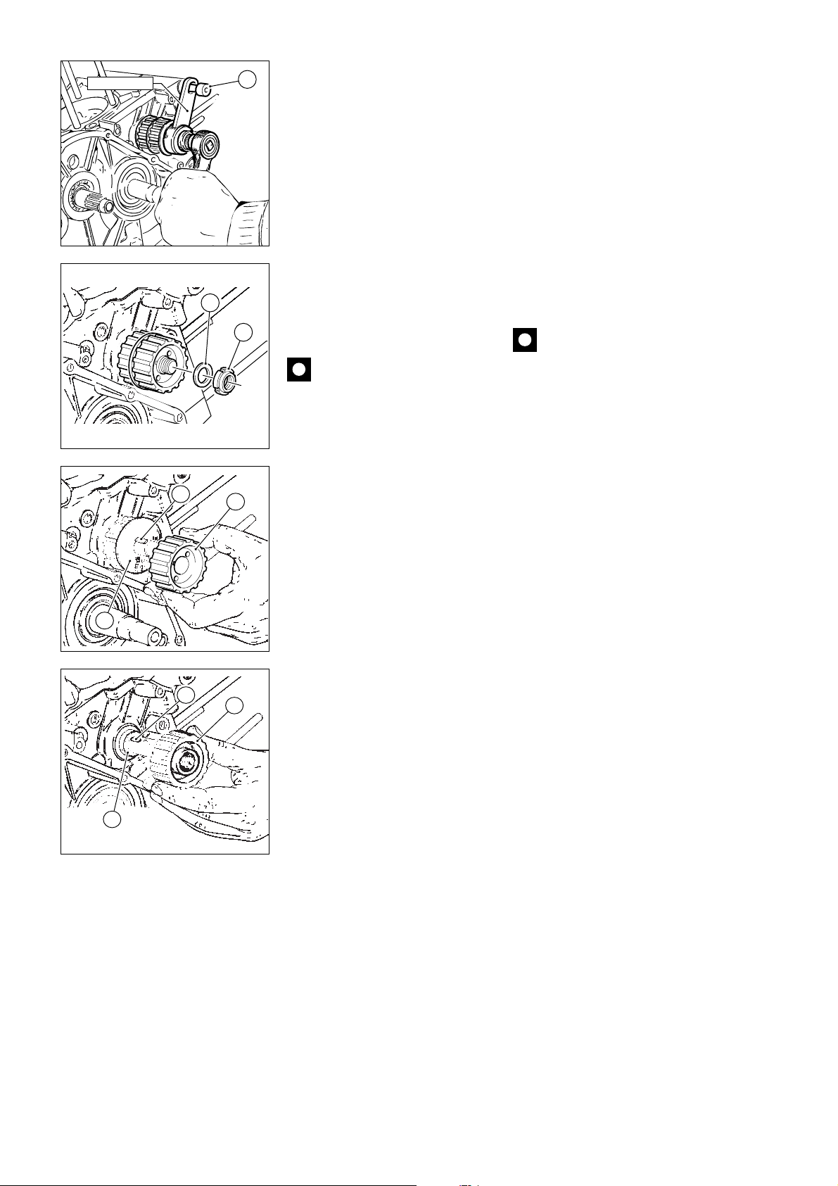
88713.1932
A
DISTRIBUZIONE
PULEGGE RINVIO
TIMING SYSTEM ROLLERS
- Fit service tool part no. 88713.1932
- Montare nei due fori non filettati
della puleggia esterna la chiave cod.
88713.1932 e bloccarne la rotazione
inserendo un perno (A) nel foro
dell’impugnatura dell’attrezzo e nella
sede della vite di fissaggio anteriore
blocco motore al telaio.
- Utilizzando la bussola dell’attrezzo
inserita in una chiave a cricchetto
allentare la ghiera di fissaggio
pulegge distribuzione.
❍
Sfilare la ghiera (1), la rosetta (2), la
puleggia esterna (3), la prima linguetta
2
(4), la rondella di guida (5), la puleggia
to the two unthreaded holes in the
outer roller. Clamp the roller in
position by inserting a pin (A)
through the hole in the tool handle
and into the front engine-frame
mounting hole.
- Fit a ratchet handle to the service
tool socket and loosen the timing
roller ring nut.
❍
Remove the ring nut (1), the
washer (2), the outer roller (3), the
first key (4), the guide washer (5),
the inner roller (3), the second key
(4) and the inner spacer (6).
interna (3), la seconda linguetta (4) e il
1
distanziale interno (6).
Caution
When reassembling, fit a new
Importante
ring nut (1) and a new washer (2).
In fase di rimontaggio,
utilizzare una ghiera (1) e una rosetta
(2) nuove.
If it becomes difficult to remove the
rollers, use the puller part
no.␣ 88713.1435 previously used to
Se l’operazione di rimozione delle
pulegge risulta difficoltosa, utilizzare
l’estrattore cod. 88713.1435,
remove the generator cover; insert
the roller into the two threaded holes
on the roller to be removed.
precedentemente utilizzato per la
4
3
rimozione del coperchio alternatore,
applicato nei due fori filettati della
puleggia da rimuovere.
5
4
6
3
40 Scomposizione motore / Engine disassembly
Page 41
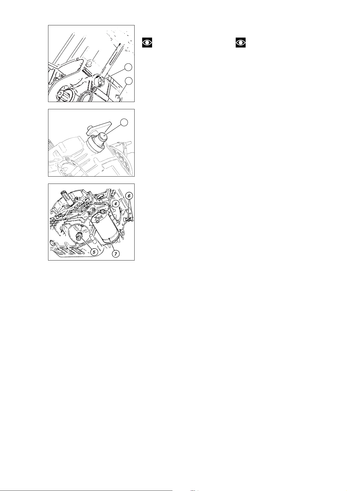
ACCESSORI BASAMENTO
CRANKCASE FITTINGS
Note
La rimozione degli elementi di
seguito illustrata è finalizzata alla
sostituzione e/o alla completa pulizia
dei semicarter. In caso di riutilizzo
2
dei semicarter la loro rimozione non
è indispensabile.
1
❍
Svitare e rimuovere il tappo (1) di
chiusura sede predisposizione spia
folle.
❍
Svitare e rimuovere il tappo (2),
con relativa guarnizione, di chiusura
3
sede puntalino scatto marce.
- Rimuovere il raccordo (3) di sfiato
vapori olio dal basamento. Per
eseguire questa operazione è
necessario munirsi di una chiave a
settore con dentino cilindrico (tipo
USAG 282/45-50).
❍
Svitare e rimuovere i 2 nippli (4) di
entrata e di uscita olio dal semicarter
frizione.
❍
Svitare e rimuovere il nipplo (5) di
supporto filtro olio.
❍
Svitare e rimuovere il tappo (6),
con relativa guarnizione, per controllo
traferro sensore di fase motore.
❍
Rimuovere il motorino
d'avviamento (7) svitando le 3 viti di
fissaggio.
❍
Rimuovere le guarnizioni cartercilindro. In caso di riutilizzo,
Note
The parts described in this
section only require removal if they
are to be changed and/or if the
crankcase halves are to be fully
cleaned. If the crankcase halves are
to be used again they need not be
removed.
❍
Unscrew and remove the blanking
plug (1) from the neutral light hole.
❍
Unscrew and remove the blanking
plug (2) and washer from the gear
stopper.
- Remove the oil breather
connector␣ (3) from the crankcase. To
remove this part use a C-spanner
with round pins (e.g. USAG 282/45-
50).
❍
Unscrew and remove the 2
nipples␣ (4) for oil infeed and outfeed
from the clutch half-casing.
❍
Unscrew and remove the oil filter
nipple (5).
❍
Unscrew and remove the plug (6)
and washer to check the timing
sensor air gap .
❍
Undo the 3 retaining screws and
remove the starter motor (7).
❍
Remove the crankcase-cylinder
gaskets. If you intend re-using the
gaskets, mark them so that they can
be refitted in the same position.
contrassegnare le guarnizioni per
poterle rimontare nello stesso
alloggiamento.
Scomposizione motore / Engine disassembly 41
Page 42
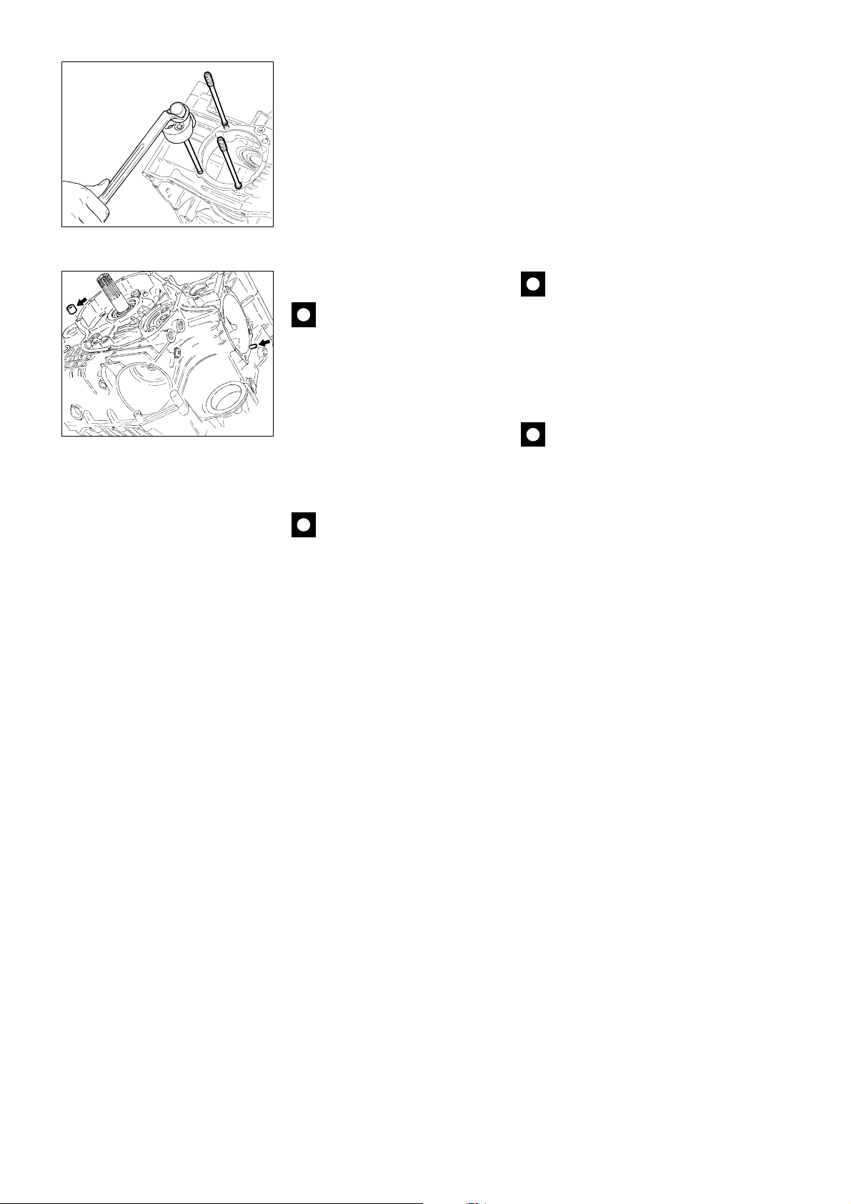
PRIGIONIERI, BOCCOLE E
GRANI DI CENTRAGGIO
STUD BOLTS, CENTRING
BUSHES AND LOCATORS
- Verificare che le aperture del carter
siano tappate con uno straccio quindi
procedere alla rimozione dei
prigionieri. Per eseguire
correttamente questa operazione è
necessario disporre di un attrezzo
che non segni eccessivamente il
prigioniero (del tipo con ganasce a
rulli). Applicare l’attrezzo in modo
che la presa avvenga alla fine della
filettatura del prigioniero, nella parte
cilindrica di diametro maggiore.
Importante
Sostituire i prigionieri che
risultano eccessivamente segnati o
rovinati dopo questa operazione.
- Se l’operazione di rimozione dagli
alloggiamenti sul carter delle boccole
di centraggio dei coperchi
alternatore, del coperchio frizione e
della pompa olio risulta difficoltosa è
consigliabile utilizzare un maschio
sinistro n
°
4 con il quale forzare in
uscita le boccole.
Importante
Sostituire sempre le boccole
rimosse.
- Ensure that all the openings in the
crankcase have been blocked off
with rags before removing the stud
bolts. To remove the stud bolts, use
a tool which will not excessively
mark the stud bolts (e.g. a tool with
roller jaws). Grip the stud bolts with
the tool at the end of the threading
on the cylindrical section with the
largest diameter.
Caution
Change all stud bolts which
are badly marked or damaged.
- If you have difficulty removing the
centring bushes (of the generator,
clutch and oil pump casings) from
the crankcase, use a left-hand n
°
4
screw tap to force the bushes out.
Caution
At reassembly, fit new bushes.
Do not refit bushes after removal.
- To remove the cylinder centring
locators, use pliers.
At re-assembly, fit new locators.
- Per quanto riguarda i grani di
centraggio dei cilindri è possibile
rimuoverli utilizzando un paio di
pinze. Anche questi è consigliabile
sostituirli, una volta rimossi.
42 Scomposizione motore / Engine disassembly
Page 43
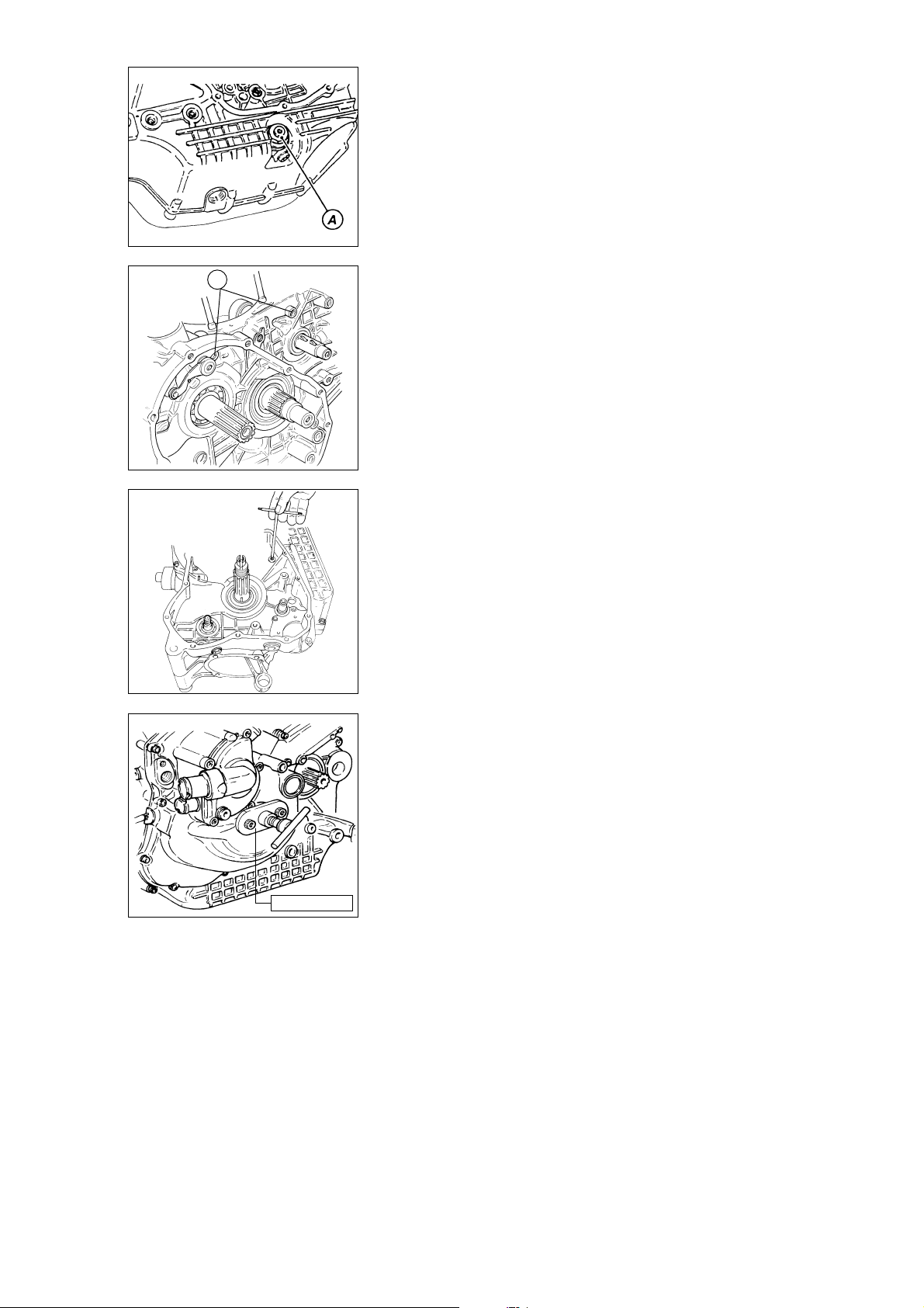
APERTURA CARTER
❍
Svitare e rimuovere dal semicarter
lato frizione il filtro a rete (A) con
relativa guarnizione.
- Svitare per prime le due viti (1),
M6x80, poste sul semicarter frizione,
in corrispondenza della sede del
cilindro verticale.
- Capovolgere il carter e svitare le
rimanenti viti di fissaggio dei due
semicarter.
1
- Riutilizzare il coperchio alternatore
(o un coperchio di servizio come
raffigurato) con l’estrattore
cod.␣ 88713.1435 montato; fissarlo al
semicarter con tre viti originali
diametralmente opposte.
- Azionare il perno centrale
dell’attrezzo e contemporaneamente
battere con un martello in plastica
sull’albero secondario del cambio
fino ad ottenere la separazione dei
semicarter.
❍
Rimuovere il semicarter
alternatore prestando attenzione ai
OPENING THE CRANKCASE
❍
Unscrew and remove the mesh
filter (A) and washer from the clutchside case-half.
- Unscrew the first two M6x80
screws (1) on the clutch-side casehalf close to the vertical cylinder.
- Overturn the case and unscrew the
other two screws on the case
halves.
- For the next operation use the
generator cover (or a service cover
as shown) fitted with the puller part
no.␣ 88713.1435. Fix this assembly to
the case half with the original three
screws fitted opposite each other.
- Turn the puller centre pin and at the
same time tap the gearbox
secondary shaft with a plastic
hammer until the two crankcase
halves separate.
❍
Remove the generator-side case
half. Take care not to lose the shims
on the gearbox shaft, the crankshaft
and the selector drum shaft.
rasamenti installati in corrispondenza
degli alberi cambio, motore e
tamburo selettore.
88713.1435
Scomposizione motore / Engine disassembly 43
Page 44
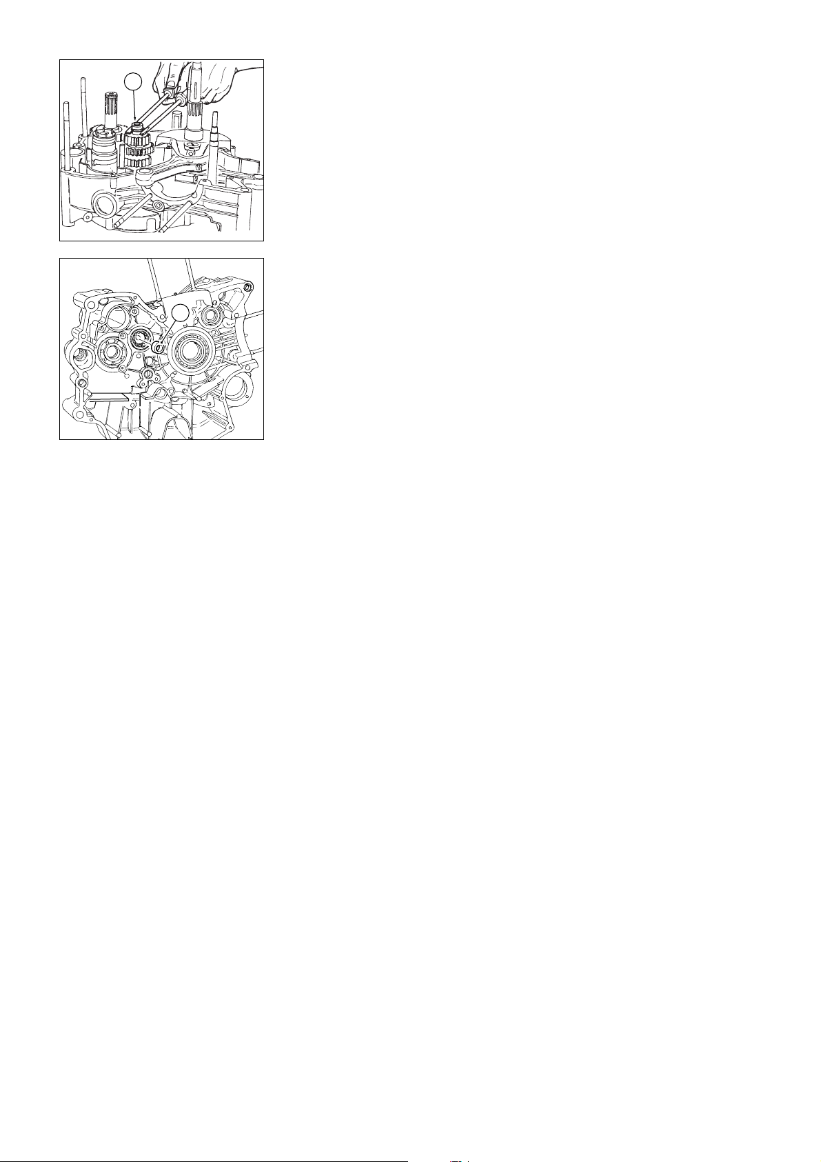
❍
Rimuovere dall’estremità
3
dell’albero primario l’anello interno␣ (3)
e introdurlo nel relativo cuscinetto sul
semicarter alternatore.
3
❍
Remove the inner ring (3) from
the end of the primary shaft and
insert it in the corresponding bearing
in the generator-side case half.
44 Scomposizione motore / Engine disassembly
Page 45
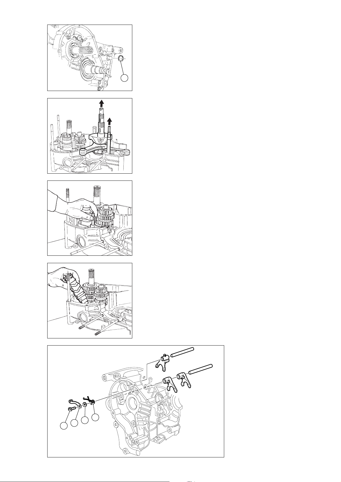
ELEMENTI INTERNI
SEMICARTER
❍
Rimuovere l’anello elastico (1)
sull’albero rinvio distribuzione, nella
parte esterna al semicarter frizione.
❍
Sfilare l’albero rinvio distribuzione
dal lato interno del semicarter.
❍
1
Sfilare l’albero motore dal
semicarter e recuperare il rasamento
interno.
❍
Sfilare gli alberi di guida delle
forcelle.
❍
Spostare le forcelle in modo da
disimpegnarle dalle cave del tamburo
selettore ed estrarre il tamburo
recuperando il relativo rasamento.
❍
Rimuovere le forcelle di innesto
delle marce.
❍
Rimuovere la levetta ferma
marce␣ (2) svitando la vite (3) di
fissaggio al semicarter. Recuperare il
rasamento (4) e la molla (5).
PARTS INSIDE THE
CRANKCASE HALVES
❍
On the outer side of the clutchside case half, remove the circlip (1)
from the timing layshaft.
❍
Remove the timing layshaft
working from the inside of the case
half.
❍
Remove the crankshaft from the
case half and recover the inner shim.
❍
Slide out the fork guide rods.
❍
Move the forks so that they
disengage from the grooves in the
selector drum. Remove the drum
and keep the shim.
❍
Remove the gear selector forks
taking care not to lose the bushes (2)
in the guide pins.
❍
Undo the fixing bolt (3) from the
case half and remove the gear stop
lever (2). Remove the shim (4) and
the spring (5).
5
4
2
3
Scomposizione motore / Engine disassembly 45
Page 46
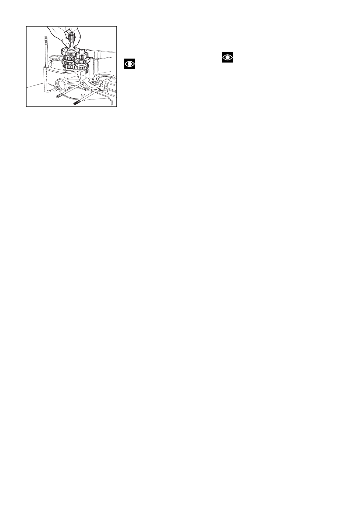
❍
Rimuovere gli alberi primario e
secondario del cambio completi di
ingranaggi e recuperare i relativi
rasamenti.
Note
Per comodità di rimontaggio si
consiglia di lasciare l’anello interno
del cuscinetto di estremità
sull’albero secondario montato su
quest’ultimo.
❍
Remove the primary shaft and
transmission shaft complete with
their gears and keep the shims.
Note
To facilitate re-assembly, leave
the inner ring of the bearing on the
end of the transmission shaft.
46 Scomposizione motore / Engine disassembly
Page 47
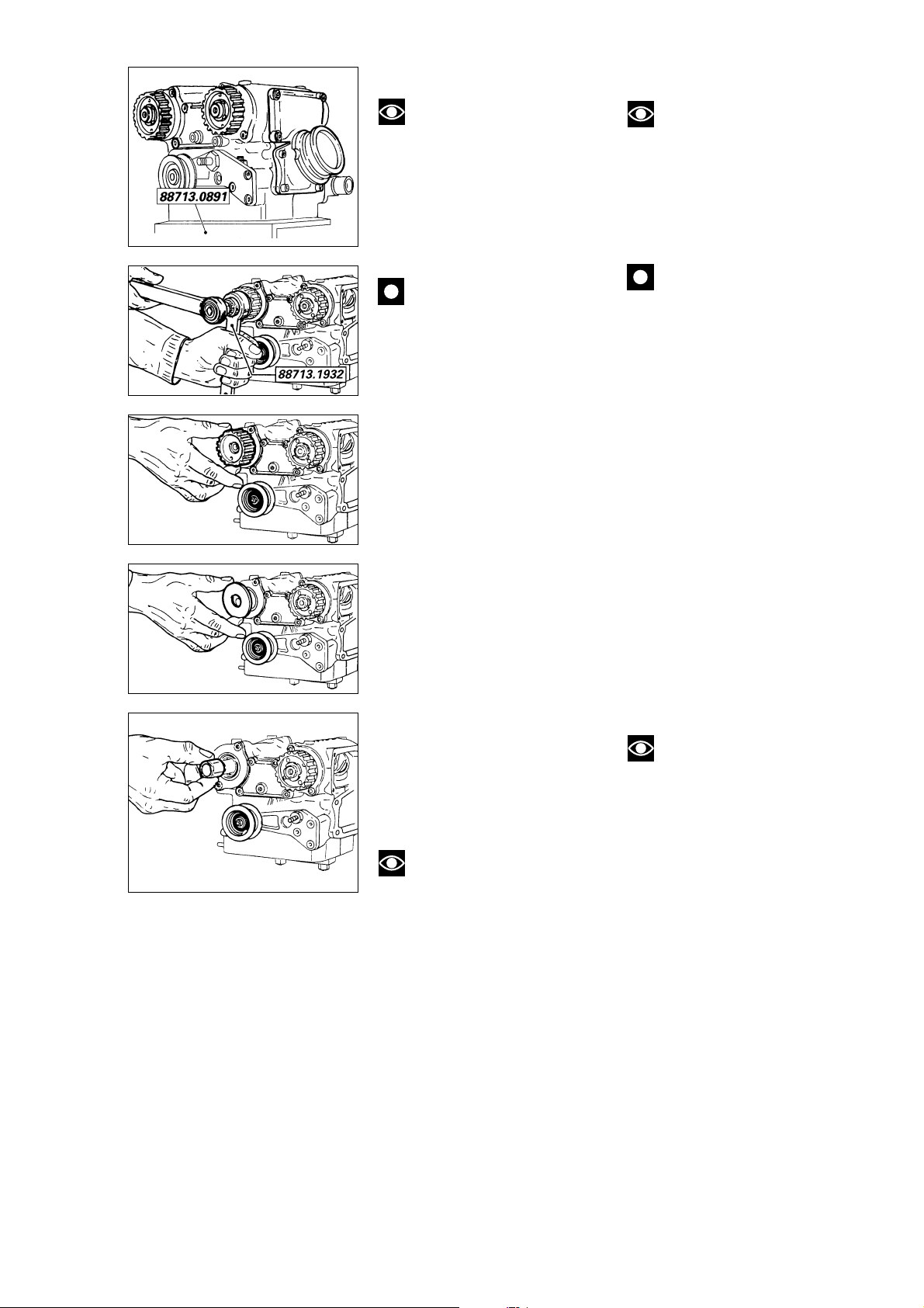
TESTE
CYLINDER HEADS
Note
Per poter eseguire con
sicurezza tutte le operazioni di
smontaggio, rimontaggio e revisione
delle teste, la Ducati fornisce una
particolare base cod. 88713.0891.
alla quale fissare la testa utilizzando
due dadi originali. La struttura della
base permette il suo bloccaggio in
morsa.
Importante
Durante lo smontaggio dei
componenti posti nella testa cilindro
è della massima importanza che essi
vengano disposti in modo opportuno,
oppure contrassegnati, al fine di
poterli rimontare nella esatta
posizione occupata prima dello
smontaggio.
❍
Rimuovere il collettore di
aspirazione svitando le quattro viti di
fissaggio.
❍
Rimuovere i coperchi di ispezione
delle camme di aspirazione e scarico
svitando le quattro viti di fissaggio.
Considerando che il coperchio lato
aspirazione viene montato con
guarnizione liquida, per facilitare il
distacco, battere con un martello di
plastica sul bordo fino al distacco
dalla testa.
●
Bloccare la rotazione della
puleggia inserendo nei due fori non
filettati i perni dell’attrezzo cod.
88713.1932. Con la bussola in
dotazione all’attrezzo inserita in una
chiave a cricchetto allentare la
ghiera.
❍
Svitare completamente la ghiera e
rimuovere la rosetta che non
andranno più utilizzate.
❍
Sfilare la puleggia dall’albero a
camme.
Note
Se l’operazione di rimozione
delle pulegge risulta difficoltosa,
utilizzare l’estrattore cod. 88713.1435,
precedentemente usato per la
rimozione del coperchio alternatore,
applicato nei due fori filettati della
puleggia da rimuovere.
Note
Ducati service tool part
no.␣ 88713.0891 is designed to
ensure safe disassembly,
reassembly and overhaul of cylinder
heads. The tool must be fixed to the
head using the 2 original nuts. The
base of the tool can be clamped in a
vice.
Caution
Cylinder head components
must be marked and laid out
carefully as they are dismantled to
ensure that they can be reassembled in the correct position.
❍
Unscrew the four retaining
screws and remove the intake
manifold.
❍
Remove the inspection covers
from the intake and exhaust cams by
unscrewing the 4 retaining screws.
The intake-side cover is assembled
using liquid gasket; tap around the
edges of the covers with a plastic
hammer to detach the covers from
the head.
●
Clamp the roller in position by
inserting the pins of service tool part
no.␣ 88713.1932 in 2 unthreaded
holes. Fit a ratchet handle to the
service tool socket and loosen the
ring nut.
❍
Unscrew the ring nut and remove
the spring washer. (Do not refit
these parts).
❍
Slide the roller off the camshaft.
Note
If it becomes difficult to
remove the rollers, use the puller
part no. 88713.1435 previously used
to remove the generator cover;
insert the puller into the two
threaded holes on the roller to be
removed.
❍
Remove the key from the
camshaft and slide off the support
washer and the inner spacer.
❍
Carry out this procedure on the
other roller and on the rollers of the
other head.
❍
Rimuovere dall’albero a camme la
linguetta e sfilare la rondella di
appoggio e il distanziale interno.
❍
Eseguire le stesse operazioni per
l’altra puleggia e sull’altra testa.
Scomposizione motore / Engine disassembly 47
Page 48
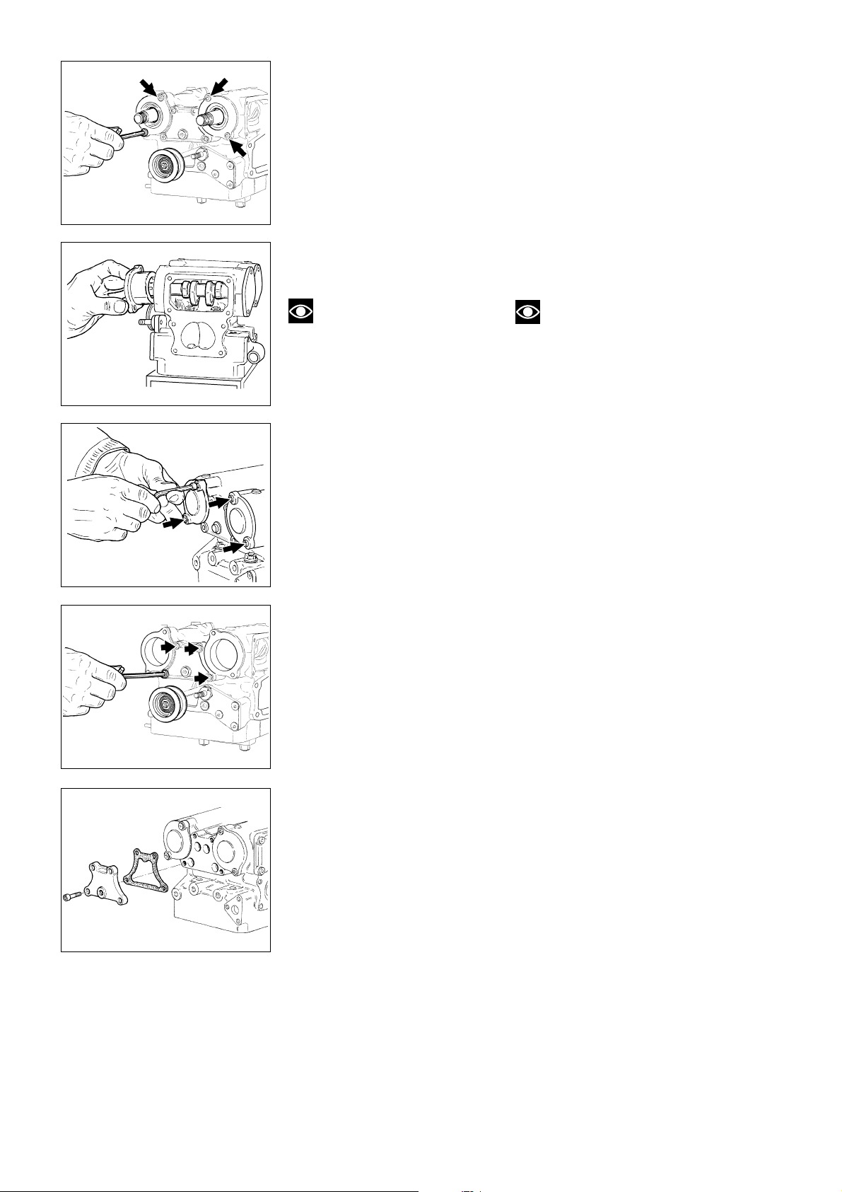
❍
Svitare le due viti di fissaggio del
supporto albero a camme, lato
pulegge distribuzione.
❍
Sfilare il supporto con albero a
camme e recuperare la guarnizione
OR. Eseguire le stesse operazioni
per l’altro supporto e sull’altra testa.
- Operando sul lato opposto della
testa, svitare le due viti di fissaggio
del supporto chiuso dell’albero a
camme.
❍
Sfilare il supporto e recuperare la
guarnizione OR.
❍
Eseguire le stesse operazioni per
l’altro supporto e sull’altra testa.
❍
Undo the 2 retaining screws of
the camshaft support, on the timing
roller side.
❍
Remove the support with
camshaft and keep the OR. Repeat
the above procedure for the other
support and head.
- Position on the other side of the
head and undo the 2 retaining
screws of the closed support of the
camshaft.
❍
Remove the support and keep the
OR.
❍
Repeat the above procedure for
the other support and head.
Note
Per lo smontaggio dei
componenti interni ai supporti albero
a camme vedi capitolo “Revisione
motore”.
❍
Rimuovere i coperchi di chiusura
delle sedi dei perni bilancieri su
entrambi i lati della testa. Recuperare
le guarnizioni.
Note
Refer to “Engine overhaul” for
removing the components inside the
camshaft supports.
❍
Remove the covers closing the
rocker arm shaft seats on both head
sides. Keep the seals.
48 Scomposizione motore / Engine disassembly
Page 49
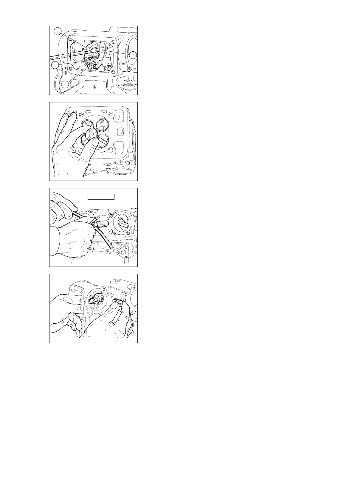
1
- Con la dovuta cautela, inserire un
perno in alluminio dall’apertura del
supporto albero a camme, facendolo
passare sotto al bilanciere di apertura
(1) e dietro al pattino (2) del
2
3
bilanciere di chiusura. In questo
modo si libererà la valvola dal vincolo
dei bilancieri e sarà possibile
rimuovere il registro di apertura (3), i
4
semianelli e il registro di chiusura (4).
- Sfilare la valvola dal lato inferiore
della testa. Eseguire la stessa
procedura per le altre valvole e
sull’altra testa.
- Utilizzando l’estrattore
cod.␣ 88713.0862 sfilare i perni dei
bilancieri e rimuovere questi ultimi
dall’interno della testa.
- Solo in caso di riutilizzo della testa,
se risultano usurati, è necessario
rimuovere gli anelli di tenuta olio alle
- Insert an aluminum pin from the
camshaft support opening with the
maximum care. It must fit under the
opening rocker arm (1) and behind
the sliding shoe (2) of the closing
rocker arm. In this way, the valve will
be free from the rocker arms and the
opening shim (3), the split rings and
the closing shim (4).
- Remove the valve from the head
bottom. Repeat the above procedure
for the other valves and head.
- Using the puller part no.
88713.0862, remove the rocker arm
shafts and take the rockers out of
the head.
- Should the head be reused, remove
worn oil seals at the valve guide
ends through the simultaneuous use
of two large flat screwdrivers. Lever
at the seal bottom and lift it gently.
estremità dei guidavalvola.
L’operazione deve essere eseguita
agendo contemporaneamente con
due cacciaviti a taglio,
sufficientemente larghi. Esercitare
una leva alla base dell’anello di
88713.0862
tenuta facendolo salire lentamente.
Scomposizione motore / Engine disassembly 49
Page 50
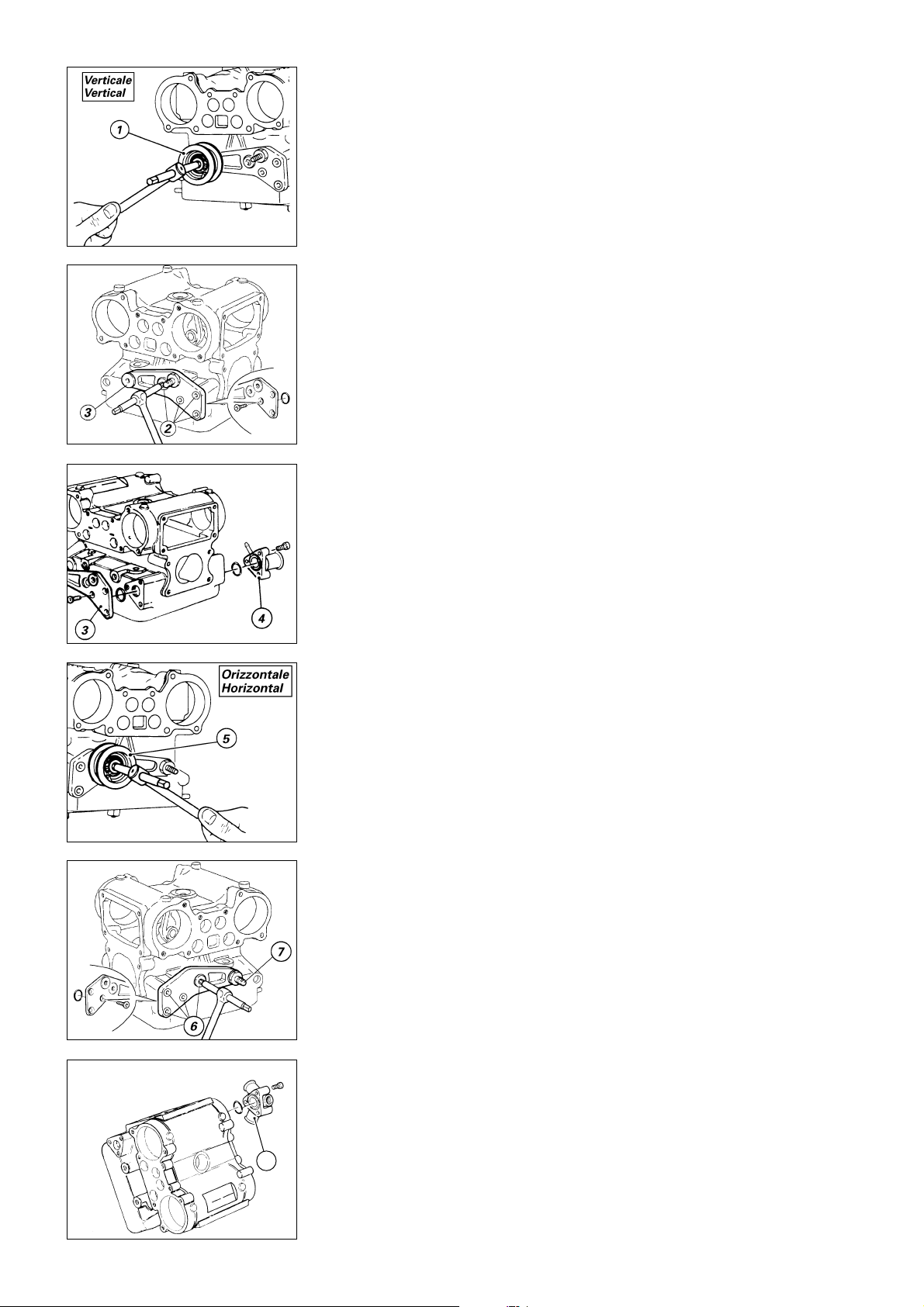
Testa verticale
❍
Rimuovere la bussola (1) tenditore
fisso dalla testa.
❍
Svitare completamente le viti (2) e
rimuovere il supporto tenditori (3)
dalla testa facendo attenzione a
recuperare la guarnizione OR del foro
acqua.
❍
Agendo sul lato opposto,
rimuovere il raccordo (4) di uscita
acqua dalla testa svitando le 3 viti di
fissaggio e recuperando la
guarnizione OR.
Testa orizzontale
❍
Rimuovere la bussola (5) tenditore
fisso dalla testa allentando prima il
grano del relativo perno.
❍
Svitare completamente le viti (6), il
perno tenditore mobile (7) e
rimuovere il supporto dalla testa.
❍
Agendo sul lato opposto,
rimuovere il raccordo (8) di uscita
acqua dalla testa svitando le 3 viti di
fissaggio e recuperando la
guarnizione OR.
Vertical head
❍
Remove the fixed tensioner bush
(1) from the head.
❍
Undo the screws (2) and remove
the belt tensioner support (3) from
the head. Remove the water hole Oring.
❍
Move round to the opposite side
of the head and remove the water
outlet connector (4) by unscrewing
the 3 retaining screws. Remove the
O-ring.
Horizontal head
❍
Loosen the dowel of the mobile
tensioner shaft and remove the
corresponding bush (5).
❍
Undo the screws (6), the mobile
tensioner pin (7) and remove the
support from the head.
❍
Move round to the opposite side
of the head and remove the water
outlet connector (8) by unscrewing
the 3 retaining screws. Remove the
O-ring.
8
50 Scomposizione motore / Engine disassembly
Page 51

Revisione motore
Engine overhaul
Revisione motore / Engine overhaul 51
Page 52

PULIZIA DEI PARTICOLARI
CLEANING PARTS
Tutti i particolari metallici devono
essere puliti e lavati con solvente
specifico, possibilmente
biodegradabile, ed asciugati con aria
compressa.
Attenzione
Durante questa operazione si
sviluppano vapori infiammabili e
particelle di metallo possono essere
espulse ad alta velocità. Si
raccomanda di operare in un
ambiente privo di fiamme libere o
scintille e di indossare occhiali
protettivi.
Soffiare con aria compressa dentro ai
condotti di passaggio olio dei
semicarter e delle teste. Togliere
accuratamente dalle superfici di
accoppiamento eventuali tracce di
sigillante, con estrema cautela, per
non danneggiarle: utilizzare a tal fine
raschietto e diluente specifico. Prima
del rimontaggio, ripassare le
filettature di alloggiamento dei
prigionieri nei semicarter e delle viti,
per eliminare i residui di Loctite o
sigillante.
All metal components must be
cleaned and washed using suitable
biodegradable solvents and then
dried with compressed air.
Warning
Cleaning solvents give off
inflammable fumes. Metal particles
may be projected at high speed from
engines during cleaning. Cleaning
with solvent must take place in
premises where there are no naked
flames or sparks. Always wear eye
protection during cleaning
operations.
Blow through the oilways in the
crankcase halves and the cylinder
heads with compressed air. Remove
residues of liquid gasket and sealant
from all contact and fastening
surfaces. Do not damage these
surfaces. Use a suitable scraper and
solvent. Before reassembling the
engine, clean all traces of Loctite and
sealant from the threads of the stud
bolt holes in the crankcase halves
and screws.
ACCOPPIAMENTI
Per consentire al motore di
funzionare nelle migliori condizioni,
fornendo quindi il massimo
rendimento, è indispensabile che
tutti gli accoppiamenti rientrino nelle
tolleranze prescritte dalla casa
costruttrice.
CLEARANCES AND FITS
To ensure top engine performance,
all the clearances and fits must be
within the tolerances specified by
the manufacturer.
52 Revisione motore / Engine overhaul
Page 53
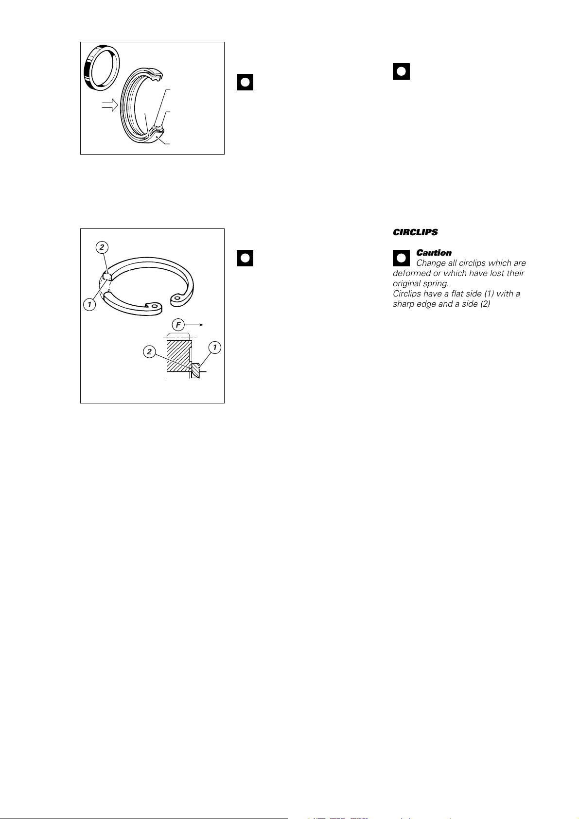
Olio
Oil
Molla
Spring
Labbro primario
Main lip
Labbro secondario
Secondary lip
Supporto
Support
SOSTITUZIONE ANELLI DI
TENUTA OLIO (PARAOLI)
Importante
Sostituire sempre i paraolio ad
ogni revisione del motore. Installare i
paraolio nuovi, inserendoli in quadro
nei loro alloggiamenti, utilizzando
tamponi adatti.
Montare sempre il paraolio con il lato
provvisto di molla, rivolto verso la
direzione di uscita dell’olio (vedi
figura).
Dopo il montaggio, lubrificare con
olio motore i labbri di tenuta del
paraolio.
CHANGING OIL SEALS
Caution
Change oil seals at each
engine overhaul. Fit new oil seals
using suitable drifts. Ensure that the
seals fit squarely in their seats.
Always fit oil seals with the spring
side facing the oil outfeed direction
(see drawing).
After fitting a new oil seal, lubricate
the seal lip with a small amount of
engine oil.
ANELLI DI ARRESTO (SEEGER)
2
Importante
Sostituire sempre gli anelli di
arresto che risultano deformati o che
hanno perduto l’elasticità originale.
Tutti gli anelli di arresto presentano
1
un lato (1) completamente piano con
spigolo vivo e un lato (2) a spigolo
F
leggermente arrotondato. Quando si
montano nelle gole degli alberi o
nelle sedi dei coperchi, il lato a
2
1
spigolo vivo (1) deve sempre essere
CIRCLIPS
Caution
Change all circlips which are
deformed or which have lost their
original spring.
Circlips have a flat side (1) with a
sharp edge and a side (2) with a
slightly rounded edge. Circlips must
be fitted to grooves in shafts and
covers with the sharp-edged side (1)
always facing the force␣ (F) applied
by the part being held in position.
opposto alla direzione della forza (F)
esercitata dall’elemento da fermare.
Revisione motore / Engine overhaul 53
Page 54
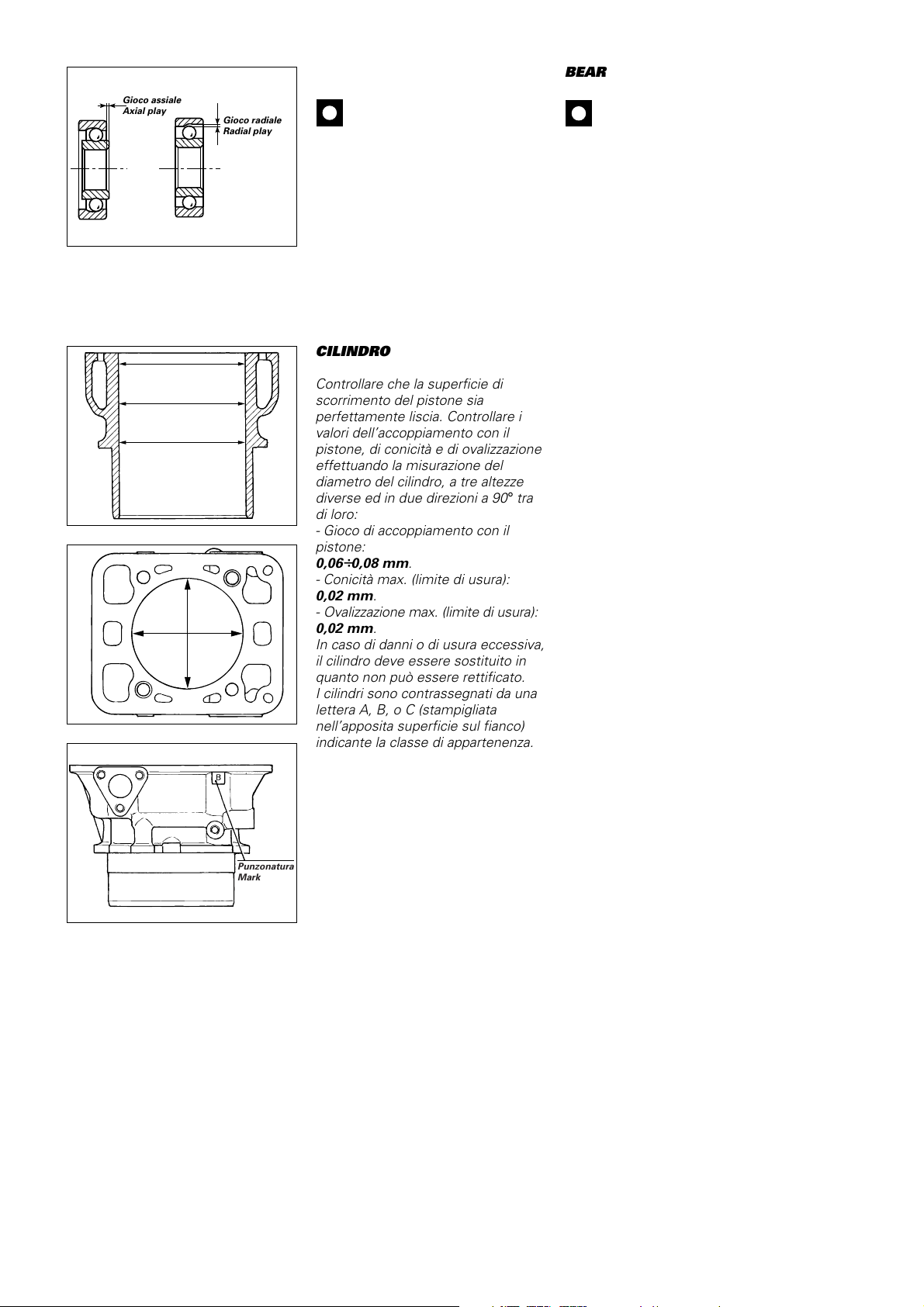
,,@@ÀÀ
,,@@ÀÀ
,,yy
,,@@ÀÀ
,,@@ÀÀ
,,yy
Gioco assiale
Axial play
Gioco radiale
Radial play
CUSCINETTI
Importante
Lavarli accuratamente con
benzina ed asciugarli con aria
compressa, senza farli ruotare.
Lubrificare leggermente e ruotare
lentamente a mano l’anello interno:
non si devono riscontrare irregolarità
di rotazione, attriti anomali o giochi
eccessivi. È buona norma
sostituire i cuscinetti ad ogni
revisione del motore.
BEARINGS
Caution
Wash bearings thoroughly with
fuel. Do not rotate bearings during
washing. Dry with compressed air.
Lightly oil the bearings. Slowly rotate
the inner ring by hand and check for
irregular rotation, jamming and
excessive play. As a general rule it
is a good idea to change bearings
at each engine overhaul.
CILINDRO
Controllare che la superficie di
scorrimento del pistone sia
perfettamente liscia. Controllare i
valori dell’accoppiamento con il
pistone, di conicità e di ovalizzazione
effettuando la misurazione del
diametro del cilindro, a tre altezze
diverse ed in due direzioni a 90
°
tra
di loro:
- Gioco di accoppiamento con il
pistone:
0,06
÷
0,08 mm.
- Conicità max. (limite di usura):
0,02 mm.
- Ovalizzazione max. (limite di usura):
0,02 mm.
In caso di danni o di usura eccessiva,
il cilindro deve essere sostituito in
quanto non può essere rettificato.
I cilindri sono contrassegnati da una
lettera A, B, o C (stampigliata
nell’apposita superficie sul fianco)
indicante la classe di appartenenza.
CYLINDERS
Check that the cylinder liners are
perfectly smooth. Measure the
cylinder diameter at three different
heights and in two positions at 90
°
to each other. Use these
measurements to check piston
clearance in bore, taper and oval.
- Piston clearance in bore:
0.06-0.08 mm.
- Max. taper (wear limit):
0.02 mm.
- Max. oval (wear limit):
0.02 mm.
Damaged or worn cylinders cannot
be rebored and must be changed.
Cylinders are punched (in a location
on the sides) with the letter A, B, or
C to indicate their class.
Punzonatura
Mark
54 Revisione motore / Engine overhaul
Page 55
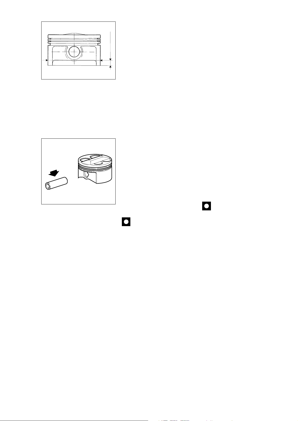
PISTONE
PISTONS
Dopo aver rimosso i segmenti, pulire
accuratamente il cielo del pistone e
le cave dei segmenti dalle
incrostazioni carboniose. Procedere
7,5 mm
ad un accurato controllo visivo e
dimensionale del pistone: non
devono apparire tracce di forzamenti,
rigature, crepe o altri danni.
Misurare il diametro del pistone a
7,5 mm dalla base del mantello, in
direzione perpendicolare all’asse
dello spinotto.
- Gioco di accoppiamento con il
cilindro:
0,06
÷
0,08 mm.
I pistoni di ricambio vengono forniti
completi di segmenti e spinotto.
SPINOTTO
Deve risultare perfettamente
lappato, senza rigature, scalini o
colorazioni bluastre dovute a
eccessivo riscaldamento. Lo spinotto
ben lubrificato deve poter scorrere
all’interno della sede del pistone
senza forzature.
- Gioco di accoppiamento con
pistone:
0,01
÷
0,02 mm.
- Limite di usura:
0,035 mm.
Importante
Se le condizioni di usura non
permettono il riutilizzo dello spinotto,
sostituirlo assieme al relativo
pistone.
Remove the piston rings. Clean all
carbon deposits from the ring
grooves and the piston crowns.
Thoroughly check pistons for wear or
damage. There must be no scoring,
scuffing, cracks or visible damage.
Measure the piston diameter at
7.5␣ mm from the skirt base at right
angles to the axis of the gudgeon
pin.
- Piston clearance in bore:
0.06-0.08 mm.
Spare pistons are supplied complete
with a set of rings and gudgeon pins.
GUDGEON PINS
Gudgeon pins must be smooth,
without scoring, stepping or blue
overheating marks. A well lubricated
gudgeon pin must rotate smoothly
and easily in its seat.
- Piston seat clearance:
0.01-0.02 mm.
- Wear limit:
0.035 mm.
Caution
Change worn gudgeon pins.
Gudgeon pins are matched with
pistons. If you change the gudgeon
pin, you must also change the
piston.
Revisione motore / Engine overhaul 55
Page 56
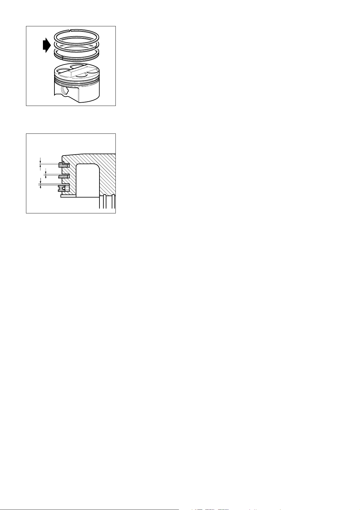
SEGMENTI
PISTON RINGS
Non devono presentare tracce di
forzamenti o rigature. Sostituire
sempre i segmenti ad ogni
revisione, consultando la tabella
degli intervalli di manutenzione
riportata all’inizio del manuale.
ACCOPPIAMENTO
SEGMENTO-CAVA SUL
PISTONE
La figura riporta il corretto gioco
assiale che deve presentare il
segmento nella relativa cava del
pistone.
- Gioco assiale max. per segmenti e
raschiaolio:
0,10 mm.
In caso di sostituzione dei segmenti,
controllare sempre prima del
montaggio il gioco assiale dei
segmenti nuovi nel pistone.
Piston rings must be free of scoring,
scuffing and signs of forcing.
Change piston rings at each
engine overhaul, respecting the
intervals indicated in the
maintenance schedule at the front of
this manual.
PISTON RING-RING GROOVE
GAP
The figure shows the correct gap
between the piston ring and the
groove.
- Piston rings and scraper ring, max.
gap:
0.10 mm.
When fitting new rings always check
the ring-groove gap first.
56 Revisione motore / Engine overhaul
Page 57
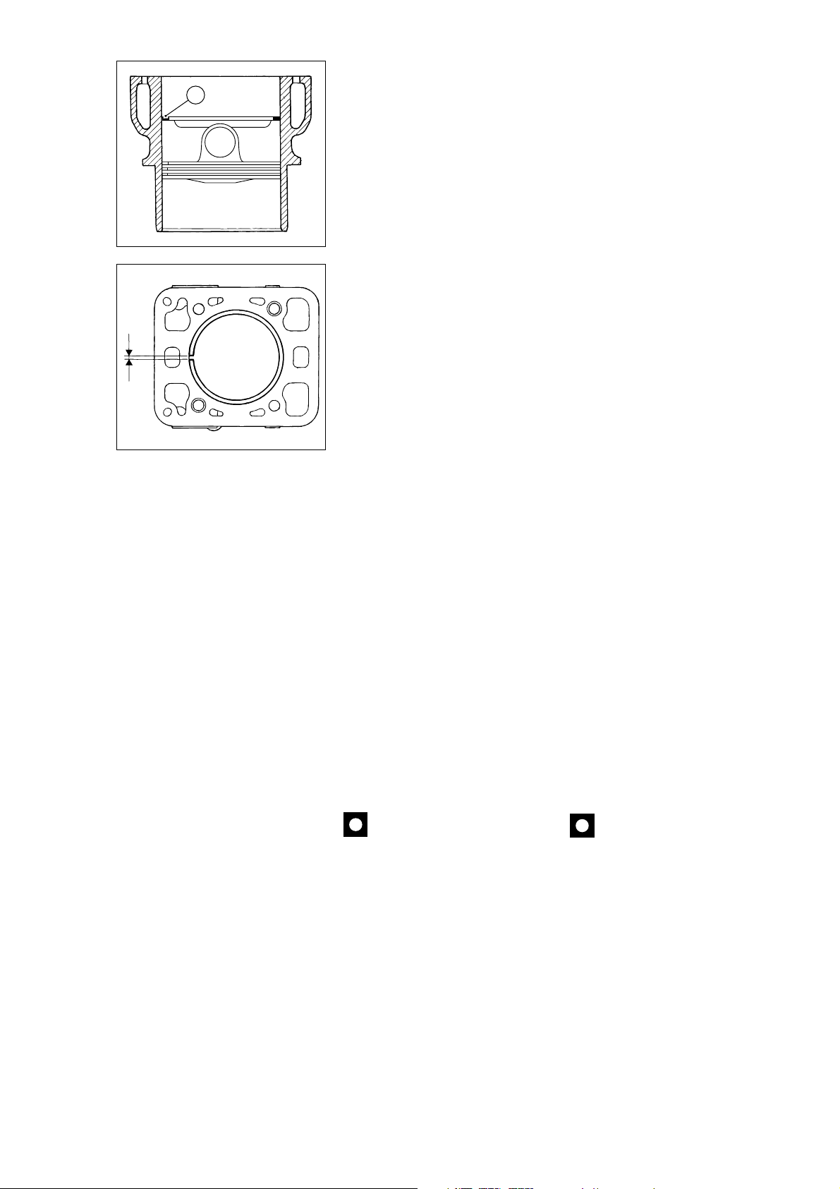
ACCOPPIAMENTO SEGMENTI-
1
CILINDRO
È importante che il rilevamento
venga fatto con segmento (1)
posizionato perfettamente
perpendicolare all’asse del cilindro. A
tal proposito inserire nel cilindro il
pistone nudo in posizione rovesciata
su cui appoggiare il segmento da
controllare (vedi figura).
Misurare la distanza tra le estremità
del segmento.
Visto la presenza di tre selezioni (A,
B, C) del gruppo cilindro/pistone
seguono i seguenti giochi:
Selezione - A
– Segmento superiore (nominale):
0,25
÷
0,53 mm.
– Segmento intermedio (nominale):
0,3
÷
0,53 mm.
– Segmento raschiaolio (nominale):
0,25
÷
0,53 mm.
Selezione - B
– Segmento superiore (nominale):
0,28
÷
0,56 mm.
– Segmento intermedio (nominale):
0,33
÷
0,56 mm.
– Segmento raschiaolio (nominale):
0,28
÷
0,56 mm.
Selezione - C
– Segmento superiore (nominale):
0,31
÷
0,59 mm.
– Segmento intermedio (nominale):
0,36
÷
0,59 mm.
– Segmento raschiaolio (nominale):
0,31
÷
0,59 mm.
PISTON RING END GAP
Measurements must be taken with
the ring (1) sitting squarely in the
bore. As an aid, insert a piston
without rings into the bore under the
ring as a support during
measurements (see drawing).
Measure the piston ring end gap.
Refer to the following values
according to the different type (A, B,
C):
Type- A
- Upper ring end gap (nominal):
0.25-0.53 mm
- Middle ring end gap (nominal):
0.3-0.53 mm
- Scraper ring end gap (nominal):
0.25-0.53 mm
Type- B
- Upper ring end gap (nominal):
0.28-0.56 mm
- Middle ring end gap (nominal):
0.33-0.56 mm
- Scraper ring end gap (nominal):
0.28-0.56 mm
Type- C
- Upper ring end gap (nominal):
0.31-0.59 mm
- Middle ring end gap (nominal):
0.36-0.59 mm
- Scraper ring end gap (nominal):
0.31-0.59 mm
IMBIELLAGGIO
Scomporre l’imbiellaggio separando
le bielle dall’albero motore.
Importante
Fare attenzione a non
scambiare le bielle tra loro e a
mantenere l’orientamento originale,
con la scritta “PANKL” rivolta verso
l’esterno (estremità albero motore,
cioé visibile ad imbiellaggio chiuso
con bielle affiancate).
Per agevolare i tecnici addetti alla
revisione dei componenti
l’imbiellaggio riportiamo un fac-simile
di “Scheda rilevamento dati”, da
utilizzare come documento per la
trascrizione e per l’archivio dei dati
rilevati sul motore.
Revisione motore / Engine overhaul 57
CONNECTING RODS
Remove the connecting rods from
the crankshaft.
Caution
Do not mix up the connecting
rods and reassemble them in their
original positions. Be sure the
“PANKL” wording is facing
outwards (crankshaft end - this
means it should be visible with the
connecting rods reassembled and
lined up side by side).
To facilitate the work of the
mechanic overhauling the con-rods
we have provided the following copy
of a “Data record sheet”. Use this
sheet to record and file engine data
measured during work.
Page 58
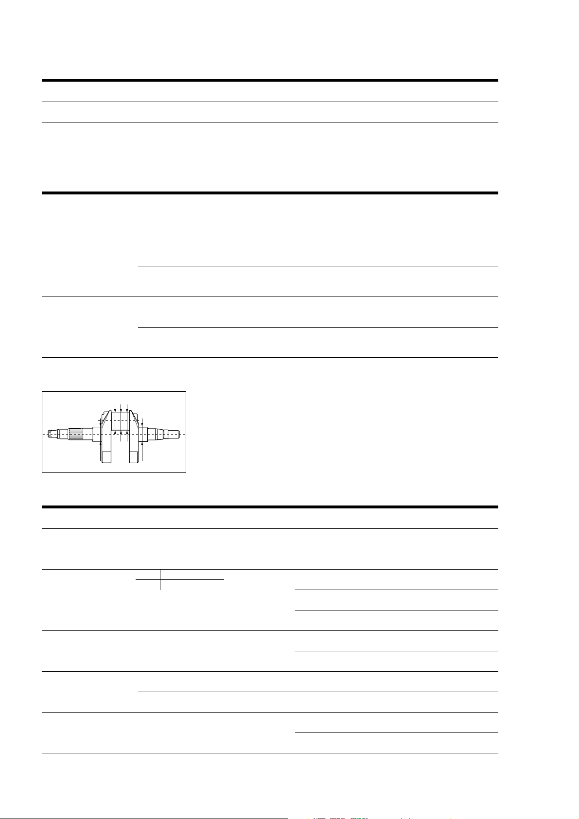
Fac-simile
SCHEDA RILEVAMENTO DATI
motore numero montaggio numero data
albero motore n° = km = Bielle km
Procedura di serraggio (vedi pagina 64)
numero numero posizione numero spessore o lunghezza lunghezza allung. coppia coppia
biella e serraggi viti serraggio selezione iniziale finale viti finale di disselezione biella viti bronzine viti viti serraggio serraggio
lato lato
frizione numero
N
°
lato
selezione
lato lato
alternatore numero
N
°
lato
selezione
Lato
alternatore
2
15
34
Lato
frizione
campo tolleranza posizione valore misurato
perno di banco 34,979÷34,995 mm lato frizione (5)
lato alternatore (1)
perno di biella sel A 42,006÷42,014 lato frizione (4)
sel B 41,998
÷
42,006
centro (3)
lato alternatore (2)
diametro testa 45,017÷45,025 mm lato frizione
di biella
lato alternatore
diametro testa di lato frizione d25° =d0
°
= d25° = dm =
biella con bronzine
lato alternatore d25° =d0
°
= d25° = dm =
gioco biella freddo 0,055÷0,065 mm lato frizione
lato alternatore
58 Revisione motore / Engine overhaul
Page 59
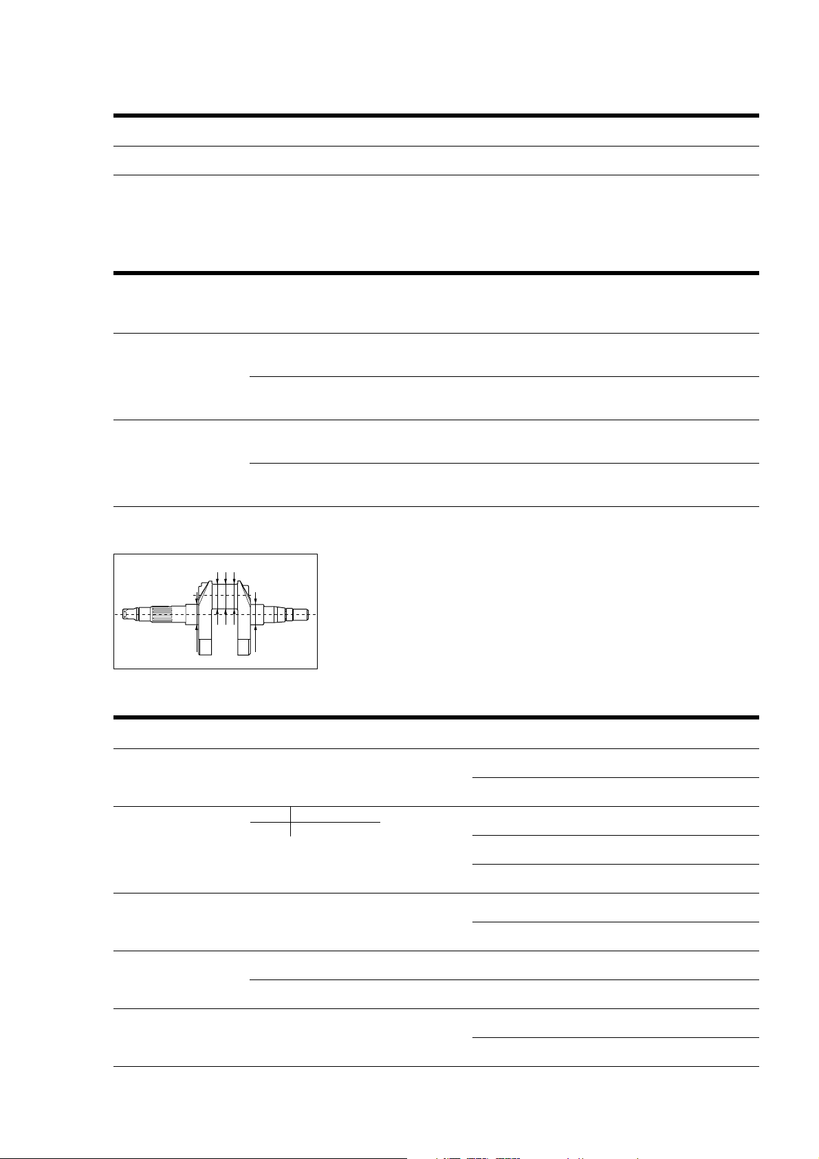
Facsimile
DATA RECORD SHEET
Engine number Assembly number Date
Crankshaft no. = km = Con-rods km
Tightening procedure (see page 64)
con-rod con-rod screw screw bear. shell screw screw screw final final
and type tightenings position tightenings thick. or initial final elong. tight. loos.
number number number type length length torque torque
clutch number
side side
no.
type
side
generator number
side side
no.
type
side
Clutch
side
2
15
34
Generator
side
tolerance range position value measured
Main bearing 34.979÷34.995 mm clutch side (5)
generator side (1)
Crankpin Type A 42,006÷42,014 clutch side (4)
Type B 41,998
÷
42,006
centre (3)
generator side (2)
Big-end 45,017÷45,025 mm clutch side
diameter
generator side
Big-end diameter clutch side d25° =d0
°
=d25
with bearing shell
generator side d25° =d0
°
=d25
°
= dm =
°
= dm =
Con-rod clearance 0.055 - 0.075 mm clutch side
(cold)
generator side
Revisione motore / Engine overhaul 59
Page 60
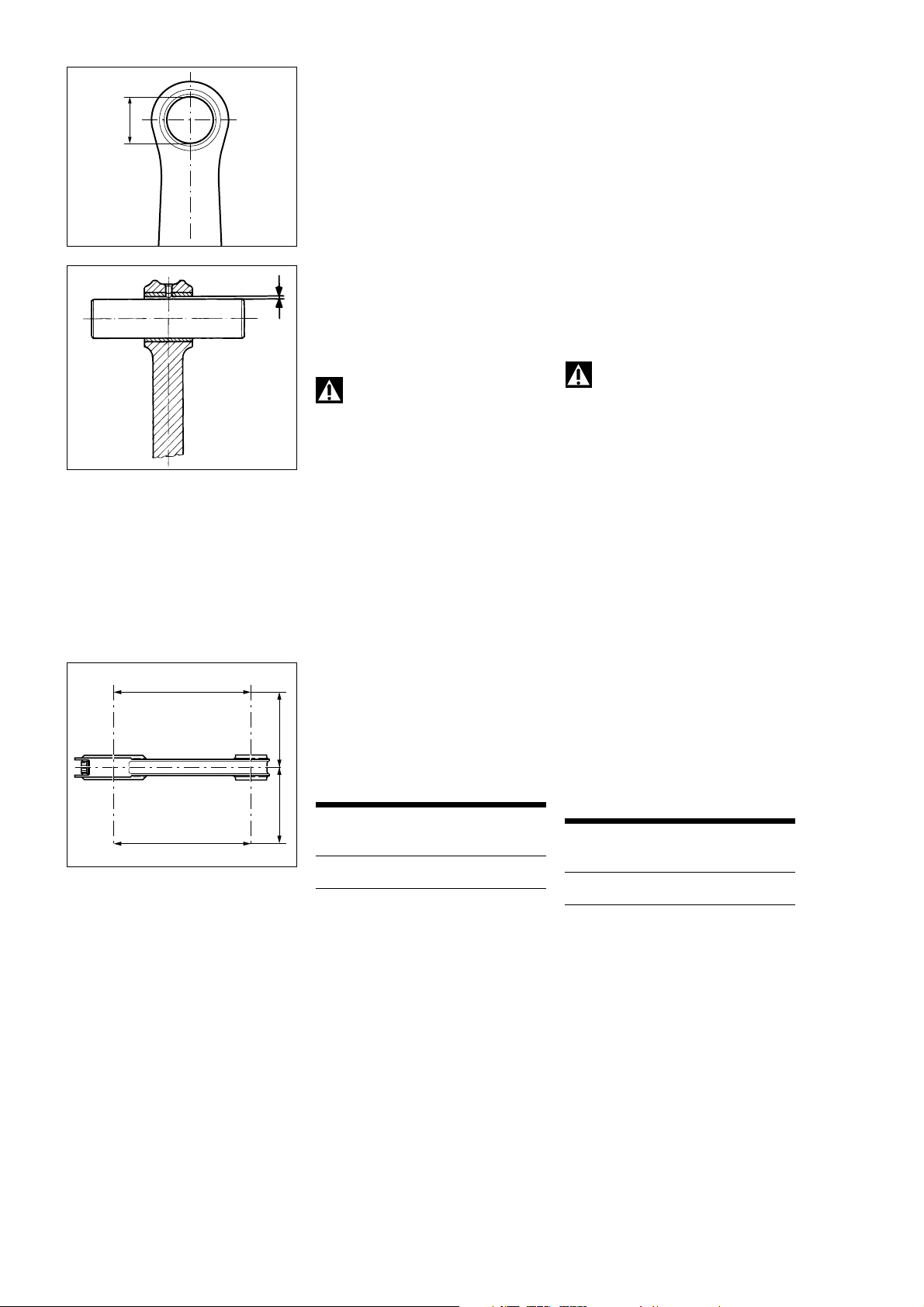
Procedere alla revisione dei
componenti l’imbiellaggio:
Inspect the components of the
connecting rods as follows:
Biella
La boccola sul piede di biella deve
risultare in buone condizioni e
saldamente piantata nel proprio
alloggiamento.
- Diametro nominale boccola piede di
biella:
20,040
÷
20,045 mm
- Gioco di accoppiamento nominale
boccola piede di biella-spinotto:
0,040
÷
0,050 mm
- Limite di usura:
0,065 mm.
In caso di usura eccessiva sostituire
la biella.
Attenzione
I pezzi in titanio devono essere
maneggiati con la massima cura.
Anche piccoli urti possono causare
cricche invisibili ad occhio nudo che
producono rotture per fatica in
funzionamento.
Connecting rods
The small-end bush must be in good
condition and securely located in its
seat.
- Nominal diameter of small-end
bush:
20.040 -20.045 mm
- Small-end bush-gudgeon pin
nominal play:
0.040 -0.050 mm
- Wear limit:
0.065 mm.
If the bush is excessively worn,
change the con-rod.
Warning
Handle titanium parts with
great care. Even minor damage can
cause cracks invisible to the naked
eye that will lead to fatigue failure in
operation.
Controllare l’errore di parallelismo
H
rilevato a 100 mm dall’asse
longitudinale della biella. Deve
risultare:
- H - h inferiore a 0,02 mm.
100 mm
In caso contrario sostituire la biella.
Measure the straightness error at
100 mm from the con-rod
longitudinal axis. The straightness
error must be:
- H - h less than 0.02 mm.
In the event of a greater error,
change the con-rod.
Esiste una sola selezione (A).
One single type of con-rod available
(A)
Selezione Diametro nominale
h
100 mm
testa di biella
Type Nominal diameter
Big-end
A 45,017÷45,025 mm
A 45,017-45,025 mm
Eliminare dal cappello e dallo stelo,
operando con tela abrasiva N. 400
bagnata nel solvente usato per
sgrassare il particolare, le eventuali
segnature prodotte dal retro della
Using emery cloth N. 400 soaked in
a degreaser, rub away any marks left
by the back of the bearing shell on
the cap and the stem.
bronzina.
60 Revisione motore / Engine overhaul
Page 61
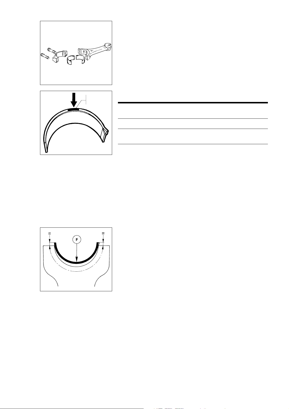
ROSSO e BLU
E
RED and BLU
Semicuscinetti
È buona norma sostituire i
semicuscinetti ad ogni revisione o
comunque secondo gli intervalli
prescritti nella tabelle delle
manutenzioni periodiche riportata
all’inizio del manuale.
I semicuscinetti nuovi vengono
forniti già pronti per il montaggio e
non devono essere ritoccati con
raschietti o tela smeriglio.
Appartengono a classi dimensionali
Connecting rod bearings
Change the bearings every time the
engine is overhauled or at regular
intervals as specified in the
maintenance schedule table at the
beginning of this manual.
Spare bearings are supplied ready for
fitting. They must not be reworked
with scrapers or emery cloth.
These bearings can belong to
different classes identified by
different colors (RED, BLUE).
identificabile ciascuna da un colore
(ROSSO, BLU).
Colore/ Codice/ Dimensione nominale/
colors code nominal dimension
+ 0,005
0
ROSSO/ 112.1.012.1AA 1,478 mm
RED
BLU/ 112.1.012.1AB 1,482 mm
BLUE
Installazione cuscinetti
- Appoggiare il semicuscinetto sulla
testa o sul cappello di biella in modo
che la sporgenza delle estremità
rispetto alla superficie di unione
risulti equidistante.
- Verificare anche che risulti centrato
assialmente nella testa o nel cappello
di biella.
- Con le dita spingere il
semicuscinetto in sede facendo
pressione (F) sulla mezzeria del
cuscinetto facendo attenzione che il
dentino corrisponda al vano ricavato
nella biella.
- Rovesciare la testa o il cappello di
biella e ripetere le stesse operazioni.
- Verificare che il semicuscinetto
risulti centrato assialmente rispetto
alla testa o al cappello di biella ed
eliminare eventuali bavature che
possono formarsi nello sfregamento
dell’estremità del cuscinetto con lo
spigolo della sede sulla biella.
Assembling the bearings
- Put the bearing onto the connecting
rod big end or cap so that an equal
portion of bearing protrudes over the
big end on either end.
- Make sure it is properly centered
with the big end or cap axis.
- Press onto the bearing axis (F) with
your fingers and make sure the tooth
is properly positioned in its seat on
the connecting rod.
- Lay the connecting rod big end or
cap on the tool and center it with
respect to the bearing surface
projection.
- Turn the connecting rod big end or
cap until it stops against the tool
retainer.
- Turn the connecting rod big end or
cap over and repeat the above
procedure.
- Make sure the bearing is centered
with the connecting rod big end or
cap axis. Remove possible fins,
which may be caused by rubbing the
bearing against its seat in the
connecting rod.
Revisione motore / Engine overhaul 61
Page 62
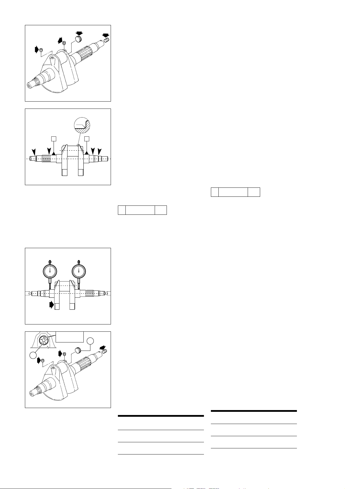
Albero motore
❍
Rimuovere tutti i tappi dall’albero
motore. Passare con lo scovolino
tutti canali e lavare con sgrassante.
Ripassare lo scovolino pulito, lavare
nuovamente e soffiare con aria
compressa.
Procedere al controllo visivo
dell’albero motore: i perni di banco e
di biella non devono presentare
solchi o rigature. Eventualmente
levigare la superficie con tela
finissima e olio. Verificare che nella
zona di raccordo tra perno e
spallamento non vi siano segni di
2 mm
lavoro o bave.
- Raggio di raccordo:
2 mm.
A
B
Le filettature, le sedi delle linguette e
le scanalature devono essere in
buone condizioni.
Rilevare con l’ausilio di un
micrometro, l’ovalizzazione del perno
di biella ed il parallellismo dell’asse
dello stesso; eseguendo i rilevamenti
Crankshaft
❍
Remove all the plugs from the
crankshaft. Clean out the oilways
with a spiral brush and wash with
degreaser. Clean out the oilways
with a clean brush and wash with
degreaser for a second time. Blow
out with compressed air.
Visually check the crankshaft. The
main bearings and the crankpins
must not be scored or grooved. If
necessary, polish the surface with
fine emery cloth soaked in oil. Check
that there is no excessive wear or
burrs in the area between the
bearing and the shoulder.
- Radius:
2 mm.
Check that the threads, keyways and
splines are in good condition.
Use a micrometer to measure the
oval of the crankpin and parallelism
of its axis in several directions:
- Crankpin axis parallelism compared
to AB:
in diverse direzioni:
- Parallellismo asse perno di biella
// Ø 0,01/100 AB
rispetto AB:
- Nominal out-of-round:
// Ø 0,01/100 AB
0.005 mm.
Selezione
Type
C
Cianfrinare
Caulk
- Cilindricità nominale:
0,005 mm.
Rilevare con comparatore
l’allineamento dei perni di banco,
posizionando l’albero motore tra due
contropunte:
- Errore di concentricità nominale:
0,01 mm
Verificare ed eventualmente
ripassare la filettatura della sede del
tappo (C); in questo caso è
necessario lavare l’albero motore.
Rimontare i tappi utilizzando THREE
BOND.
Serrare i tre grani filettati alla coppia
prescritta.
C
Avvitare il tappo in alluminio (C) fino
ad avere la massima sporgenza del
tappo dal piano mannaia, senza
toccare il rasamento (tra mannaia e
cuscinetto di banco) posto nella sua
Fix the crankshaft between two
centres and then use a dial gauge to
check the alignment of the main
bearings.
- Nominal out-of-round error:
0.01 mm
Check and if necessary re-tap the
threads of the plug hole (C). If you
re-tap the thread, you must wash the
crankshaft again.
Refit the plugs using THREE BOND
and tighten the three threaded
dowels to the specified torque.
Tighten the aluminium plug (C) so that
a max. portion of plug protrudes over
the blade. Do not remove the shim
placed between blade and main
bearing - max. value 0.2 - 0.3 mm
approx.
posizione di funzionamento (max
sporgenza ~ 0,2
÷
0,3 mm).
Crankshafts are classified into two
types: A and B. The type is punched
Ogni albero motore è classificato da
due selezioni A e B, punzonate sul
fianco mannaia, lato pignone, riferite
on the side of the blade on the
sprocket side near to the main
bearing.
al perno di biella.
Type Nominal diameter
Selezione Diametro nominale
A 42.006 - 42.014 mm
A 42,006÷42,014 mm
B 41.998 - 42.006 mm
B 41,998÷42,006 mm
62 Revisione motore / Engine overhaul
Page 63
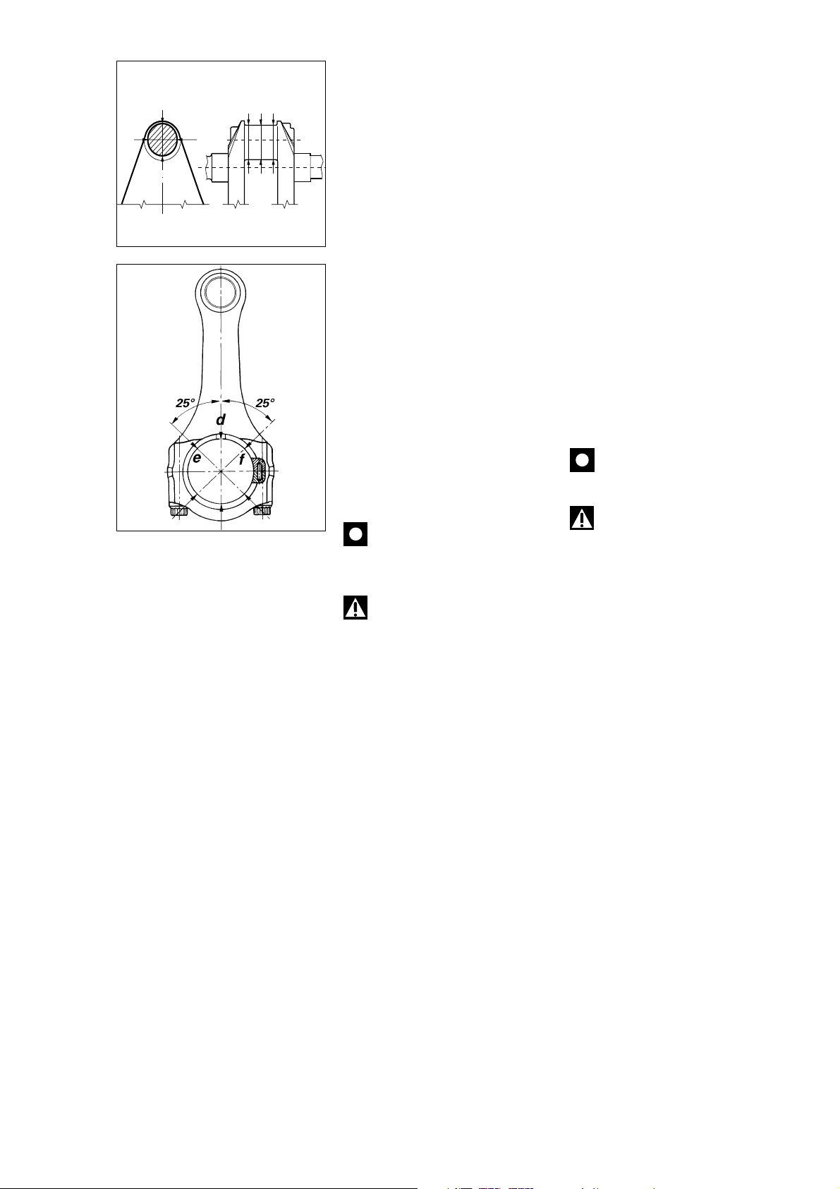
ACCOPPIAMENTO
SEMICUSCINETTI-PERNO
1
a
c
BIELLA
Per verificare il gioco di
2
accoppiamento tra semicuscinetti e
albero motore procedere come
segue:
- Rilevare il diametro del perno di
biella nelle posizioni indicate (a - c).
In riferimento agli assi ortogonali (1 -
2), determinare il valore medio.
- Serrare le viti della biella, alla coppia
prescritta, con i cuscinetti.
- Rilevare il diametro interno in
riferimento agli assi (d - e - f) e
BIG-END BEARING CRANKPIN CLEARANCE
To check the clearance between the
big-end bearings and the crankpin
proceed as follows:
- measure the crankpin diameter in
the specified positions (a - c).
Calculate the average value at right
angles (1 - 2).
-
Tighten the con-rod bolts to the
specified torque (with bearings).
- Measure the internal diameter of
the con-rod with reference to (d - e f) axes. Calculate the average value.
Use the formula:
determinare il valore medio.
- Applicare la formula:
Clearance = Con-rod diameter (with
bearings) - Crankpin diameter
Gioco di accoppiamento = Diametro
biella (con cuscinetti) - Diametro
perno.
Nominal clearance:
0.055-0.065 mm
Gioco di accoppiamento nominale:
0,055
÷
0,065 mm
Scegliere lo spessore dei
semicuscinetti nella classe di
appartenenza, che permetta la
migliore centratura.
Importante
Evitare di utilizzare imbiellaggi
che presentano un gioco inferiore a
0,055 mm.
Attenzione
I pezzi in titanio devono essere
maneggiati con la massima cura.
Anche piccoli urti possono causare
cricche invisibili ad occhio nudo che
producono rotture per fatica in
funzionamento.
Select a bearing for proper centering
(refer to bearing classes).
Caution
Do not use bearings with
clearances of less than 0.055 mm.
Warning
Handle the titanium parts with
great care. Even minor damage can
cause cracks invisible to the naked
eye that will lead to fatigue failure in
operation.
Revisione motore / Engine overhaul 63
Page 64
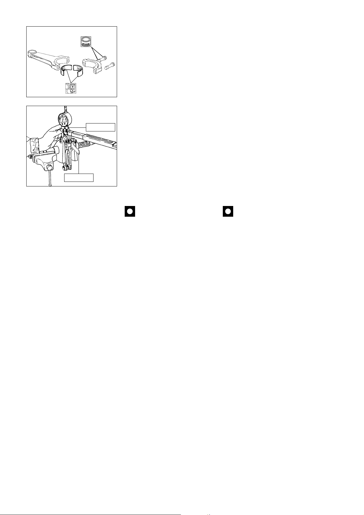
PANKL PLB 05
E
88713.1309
88713.1781
RICOMPOSIZIONE
DELL’IMBIELLAGGIO
Lubrificare abbondantemente con
olio motore e disporre sull’albero
motore le bielle e relativi cappelli,
mantenendo, in caso di riutilizzo dei
componenti originali, la posizione e
l’orientamento che avevano prima
dello smontaggio.
Interporre tra le bielle lo spessimetro
a forchetta cod.88713.1309 di
spessore 2,35 mm per anullare il
gioco assiale bielle-perno.
Lubrificare filetto e sottotesta delle
viti di fissaggio con grasso PANKL.
Procedura di serraggio viti:
1) effettuare l’avvicinamento
manuale.
2) preserrare le viti, controllando un
allungamento di 0,05
tramite l’attrezzo cod. 88713.1781
(micrometro).
3) effettuare il serraggio finale,
controllando allungamento (0,155
0,005 mm).
±
0,005 mm,
±
REASSEMBLING THE
CONNECTING RODS
Oil the con-rods and caps with
generous amounts of engine oil and
then fit them to the crankshaft. If
you are using parts dismantled
previously, make sure that you fit
these parts back into their original
positions and facing in the original
direction.
Insert the fork feeler gauge part no.
88713.1309, thickness 2.35 mm
between the con-rods to eliminate
the connecting rods - crankpins axial
play.
Grease threads and underside of the
bolt heads with PANKL grease.
Tightening procedure:
1) Snug bolts manually.
2) Preliminary tightening: use tool
no. 88713.1781 (micrometer), and
check bolt stretch, it should be 0.05
±
0.005 mm.
3) Final tightening. Check stretch
(0.160
±
0.005 mm).
Importante
Le viti di biella possono essere
utilizzate solo per tre serraggi
(compreso il serraggio iniziale del
fornitore).
Si consiglia di utilizzare viti di servizio
per effettuare le misure delle bielle.
Caution
The con-rod bolts may be used
for a total of 3 tightenings only
(including the supplier’s original
tightening).
Use service bolts to carry out conrod measurements.
64 Revisione motore / Engine overhaul
Page 65
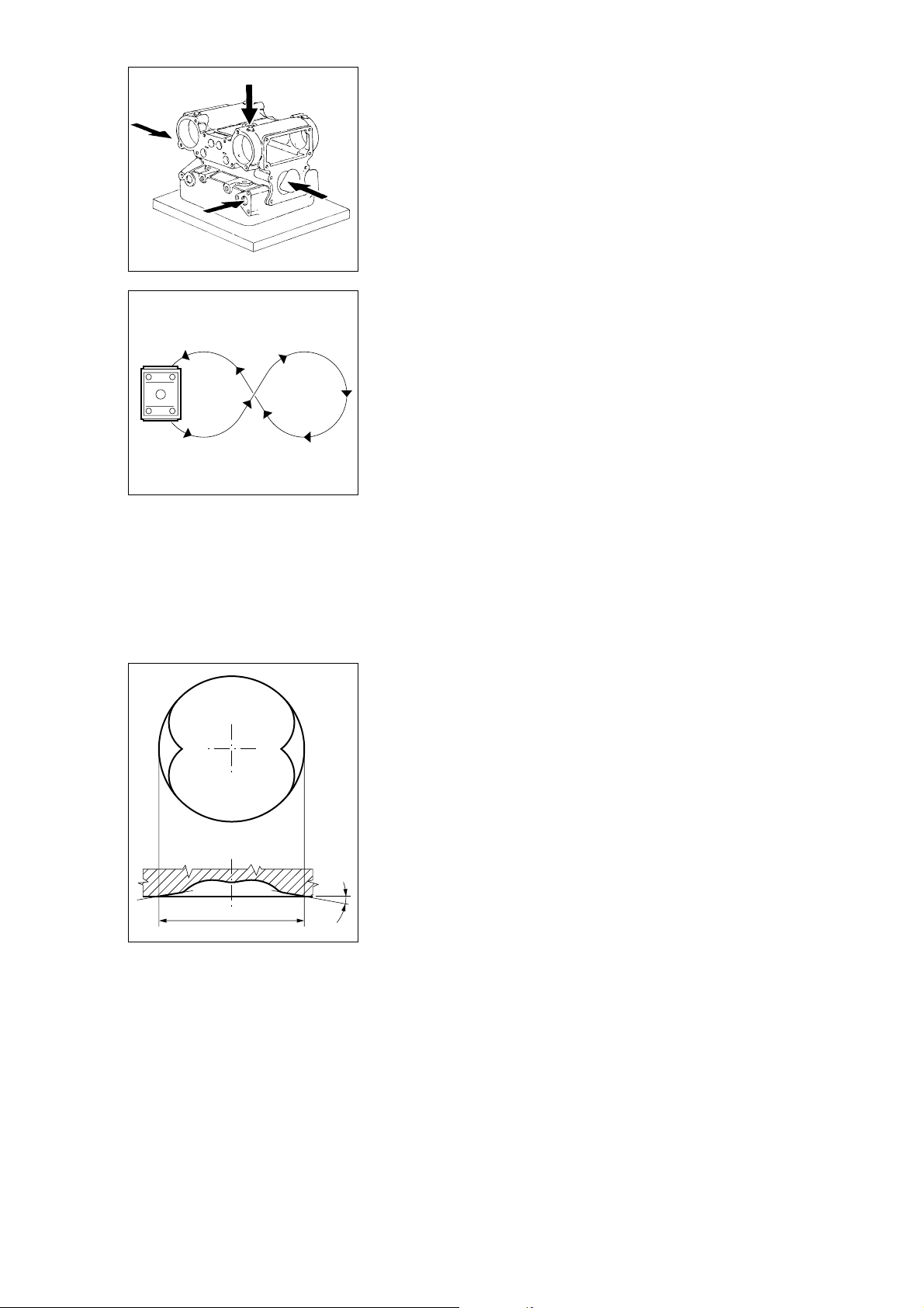
Testa
Rimuovere i depositi carboniosi dalla
camera di combustione e dai relativi
condotti. Pulire da eventuali
incrostazioni le canalizzazioni del
liquido di raffreddamento. Controllare
che non vi siano crepe e che le
superfici di tenuta risultino prive di
solchi, scalini o altri danni.
La planarità della superficie di
accoppiamento con il cilindro deve
essere perfetta. In caso contrario,
applicare su di un piano di riscontro
sospensione diamantata (spessore
6
÷
12 micron) e ripassare la
superficie muovendo la testa come
evidenziato in figura, fino ad ottenere
un piano uniforme.
Cylinder heads
Remove carbon deposits from the
combustion chamber, ports and
ducts. Clean off scaling and deposits
from coolant ducts. Check the head
for cracks. Check that the contact
surfaces are smooth and without any
scoring, steps or damage.
The contact surfaces with the
cylinder must be perfectly flat. If this
is not the case, apply a grinding
solution (6-12 micron thickness) to a
reference surface and grind the
surfaces by passing the head across
the table as shown in the drawing.
Continue until you obtain a perfectly
flat surface.
ø 87,8 ÷ 88 mm
28˚
In caso di consistenti spianature del
piano testa è necessario ripristinare
la superficie di “squish” per evitare
che il cielo del pistone al PMS possa
originare impatti. Attenersi alle quote
di figura per ripristinare la superficie
di “squish”.
If the head surfaces have been
considerably flattened, it will be
necessary to rework the squish
surfaces to prevent collisions with
the piston crown at TDC. Use the
measurement given in the drawing
for the squish surfaces.
Revisione motore / Engine overhaul 65
Page 66
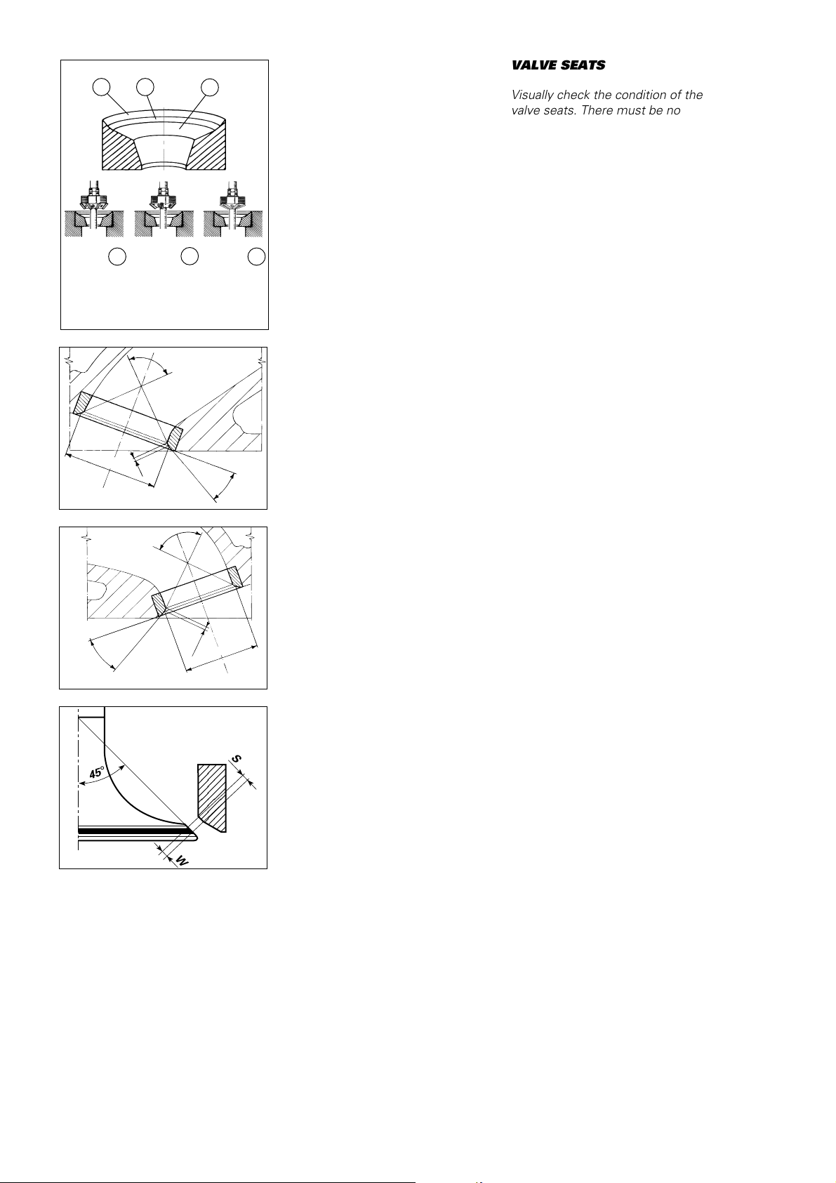
SEDE VALVOLA
23
1
Controllare visivamente le sedi: non
devono presentare tracce di
vaiolature o incrinature.
Riscontrando lievi danni è possibile
eseguire una fresatura utilizzando
apposite frese monotaglienti:
da 75
°
(fascia 1 SCARICO), 60
°
(fascia 1 ASPIRAZIONE), 45° (fascia
2 ASPIRAZIONE e SCARICO), 30
(fascia 3 ASPIRAZIONE e SCARICO).
VALVE SEATS
Visually check the condition of the
valve seats. There must be no sign
of pitting or cracking. Slight damage
can be removed using a single blade
reamer of adequate size: 75
EXHAUST radius 1, 60
radius 1, 45 ° for radius 2 on both
INTAKE and EXHAUST and 30
°
radius 3 on both INTAKE and
EXHAUST.
°
for
°
for INTAKE
°
for
FASCIA
RADIUS
75°
Scarico
Exhaust
60°
Aspirazione
Intake
Ø 35,6
Aspirazione
Intake
30
°
Scarico
Exhaust
45
°
1
±
0,025
FASCIA
RADIUS
45
°
90
°
(1,2)
90
°
2
(1,2)
Ø 29,6
FASCIA
RADIUS
30
°
30
°
0,025
±
S
3
(mm)
(mm)
In caso di danni eccessivi alle sedi
valvola è possibile eseguirne la
sostituzione utilizzando sedi
maggiorate di 0,03 e 0,06 mm, sul
diametro esterno, disponibili a
ricambio. Operare come segue:
- rimuovere le sedi usurate
fresandole con cautela per non
danneggiare l’alloggiamento sulla
testa;
- controllare il diametro degli
alloggiamenti sulla testa e scegliere
la sede valvola maggiorata più
idonea, considerando una
interferenza di montaggio di
0,04
÷
0,1 mm;
- scaldare lentamente ed
uniformemente la testa fino ad una
temperatura di 150
°
C e raffreddare
le nuove sedi con ghiaccio secco;
- piantare le sedi perfettamente in
quadro nel proprio alloggiamento
utilizzando gli appositi punzoni
cod.␣ 88713.1935 (ASPIRAZIONE) e
cod. 88713.1934 (SCARICO);
- lasciare raffreddare la testa e quindi
procedere alla lavorazione delle sedi
facendo riferimento alle quote di
figura.
Dopo la lavorazione delle sedi è
importante verificare la tenuta tra
valvola e sede: se la superficie di
contatto sulla sede (S) dovesse
risultare maggiore del tratto a 45
°
sulla valvola (W) si potrebbero
verificare problemi di tenuta.
Badly damaged valve seat inserts
must be removed and replaced with
oversize inserts. Fit new inserts with
outer diameters oversized by 0.03
and 0.06 mm. Oversize seat inserts
are available as spare parts. To fit,
proceed as follows:
- Mill out the old inserts taking care
not to damage the valve seat
locations.
- Check the diameter of the locations
in the head and choose the most
suitable oversize insert taking into
account a negative allowance
of 0.04-0.1 mm;.
- Slowly and uniformly heat the head
to a temperature of 150
°
C. Cool the
new seat inserts with dry ice.
- Drive the new seats squarely into
their locations using the drifts part
no. 88713.1935 (INTAKE) and part
no. 88713.1934 (EXHAUST).
- Allow the head to cool down and
then machine the new seats as per
the measurements given in the
drawing.
When machining of the seats has
been completed, check the seal
between the valve and the seat. If
the contact surface on the seat (S) is
greater than the 45
°
seating surface
on the valve (W), this may cause
poor sealing.
W
66 Revisione motore / Engine overhaul
Page 67
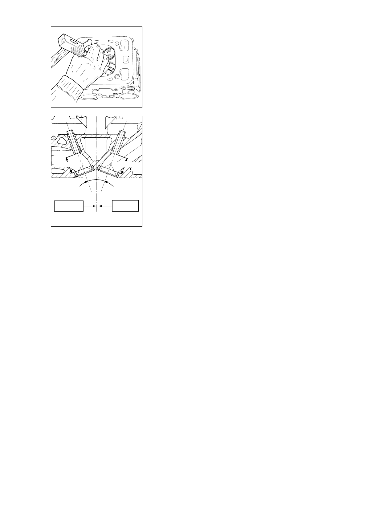
GUIDAVALVOLA
VALVE GUIDES
25,5 ± 0,15
Scarico
Exhaust
Asse candela
Spark plug axis
Procedere al controllo delle
condizioni della superficie interna dei
guidavalvola: non devono apparire
Check the condition of the inner
surfaces of the valve guides. There
must be no cracking or deformation.
incrinature o deformazioni.
Valve guides are available with outer
Sono disponibili a ricambio
guidavalvola con maggiorazione sul
diametro esterno di 0,03, 0,06 e
0,09 mm.
Per eseguire la sostituzione operare
come segue:
- riscaldare lentamente ed
uniformemente la testa fino alla
temperatura di 150
°
C;
- rimuovere i guidavalvola originali
utilizzando il punzone
cod.␣ 88713.0879;
- lasciare raffreddare la testa e
verificare le condizioni degli
25,5 ± 0,15
alloggiamenti dei guidavalvola;
- scegliere i guidavalvola più idonei
°
20
20
°
Aspirazione
Intake
per ottenere una interferenza di
montaggio con la testa di
0,022
÷
0,051 mm;
- riscaldare nuovamente la testa e
Asse cilindro
Cylinder axis
raffreddare con ghiaccio secco i
guidavalvole nuovi;
- lubrificare i fori ed installare i
(mm)
guidavalvola utilizzando gli appositi
attrezzi:
aspirazione cod. 88713.1933
diameters oversized by 0.03, 0.06
and 0.09 mm.
To change valve guides, proceed as
follows:
- Slowly and uniformly heat the head
to a temperature of 150
°
C.
- Remove the original valve guides
using the drift part no. 88713.0879.
- Allow the head to cool and check
the condition of the guide locations.
- Select a suitable guide valve
diameter allowing for an assembly
allowance of 0.022 - 0.051 mm.
- Heat the head again and cool the
new valve guides with dry ice.
- Lubricate the valve guide bores in
the head and fit the new valve
guides using the follow service tools:
intake valve guide drift
part␣ no.␣ 88713.1933
exhaust valve guide drift
part␣ no.␣ 88713.0874.
Use the measurements shown in
the drawing.
- Ream the contact surfaces to make
them uniform.
scarico cod. 88713.0874
Fare riferimento alla quota riportata
in figura;
- ripassare un alesatore per rendere
più uniforme la superficie di
accoppiamento.
Revisione motore / Engine overhaul 67
Page 68
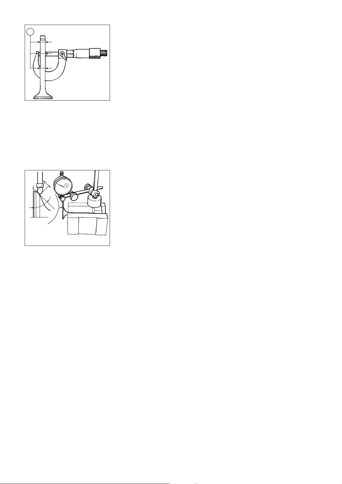
B
Controllare che lo stelo e la
superficie di contatto con la sede
valvola siano in buone condizioni.
Non devono apparire vaiolature,
incrinature, deformazioni o tracce di
usura.
Misurare il diametro (B) della zona di
lavoro dello stelo, a diverse altezze;
deve risultare un gioco di montaggio
tra valvola e guidavalvola di:
- ASPIRAZIONE e SCARICO:
0,025
÷
0,045 mm (nominale).
VALVOLA
VALVES
The valve stems and valve seating
faces must be free of pitting, cracks,
deformation or signs of wear.
Measure the diameter (B) at various
heights in the stem working area.
The assembly allowances between
the valve stem and the valve guide
are:
- INTAKE and EXHAUST:
0.025 -0.045 mm (nominal).
Wear limit:
0.08 mm
Limite di usura:
0,08 mm.
W
45
Verificare la concentricità, rispetto
allo stelo, della superficie a 45
°
della
testa, sistemando un comparatore
°
ad angolo retto con la testa e
ruotando la valvola in appoggio su di
un riscontro a “V”:
- Concentricità nominale:
0,03 mm.
Limite di servizio:
0,08 mm.
Verificare mediante “blu di Prussia”
o miscela di minio e olio, che la
superficie di contatto (W) tra valvola
e sede risulti completa, uniforme e
centrata sul tratto a 45
°
della valvola.
Check the out-of-round (with the
stem as a reference) of the 45
°
seating face. Rest the valve in a “V”
reference block and use a dial gauge
at right angles to the head while
turning the valve in the block.
- Nominal out-of-round:
0.03 mm
Service limit:
0.08 mm
Use “Prussian blue” or a minium oil
mixture and check that the contact
surface (W) between the valve and
the valve seat is complete, uniform
andcentered on the 45
°
valve
seating face.
68 Revisione motore / Engine overhaul
Page 69
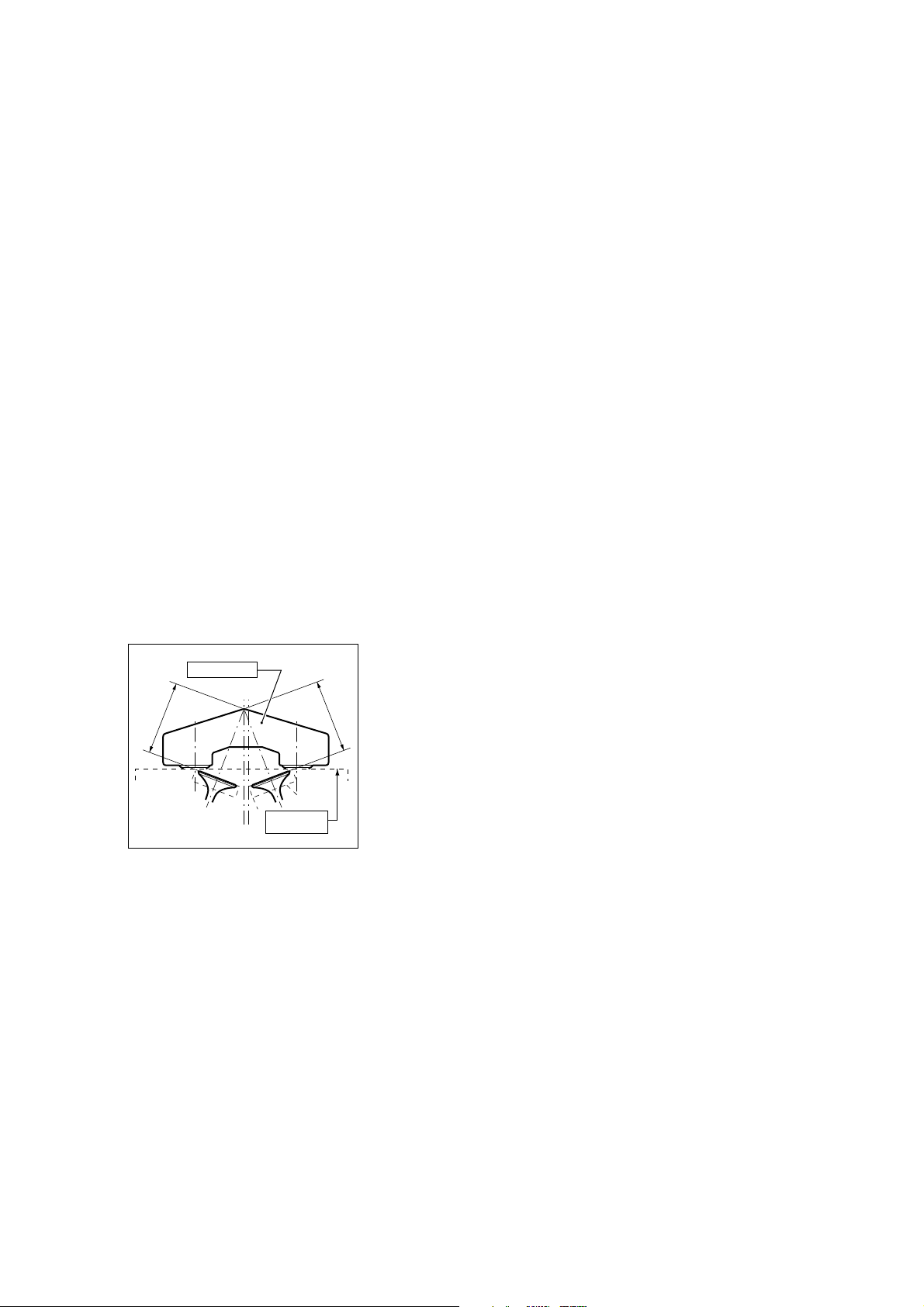
CONTROLLO TENUTA
VALVOLE
La seguente procedura può avvenire
sia in sala prova che a motore
montato sul veicolo.
– Portare a regime termico il motore
(olio ed acqua a 80
°
circa), quindi
spegnerlo.
– Partire con il controllo del cilindro
orizzontale.
– Togliere la candela.
– Inserire connettore MOTOMETER
nel filetto candela (cod. 88765.1140).
– Aprire le farfalle al 100%.
– Trascinare il motore a 1500 min
-1
(nel caso di procedura sul veicolo,
utilizzare avviatore ruota posteriore).
– Leggere sullo strumento il valore di
compressione: se inferiore a 12,5
ripristinare la tenuta valvole.
– Ripetere la procedura sul cilindro
verticale.
VALVE LEAK TEST
This test can be done either in a test
room or with the engine in the
frame.
- Let the engine warm up to
operating temperature (oil and water
at 80
°
approximately), then stop it.
- Check the horizontal cylinder first.
- Remove the spark plug.
- Screw the MOTOMETER
connector into the spark plug thread
(part no. 88765.1140).
- Open the throttles fully.
- Crank the engine to 1,500 rpm (if
you are doing the test with the
engine in the frame, use the rear
wheel starter).
- Check the compression reading on
the meter. If it is less than 12.5, you
will need to overhaul the concerned
area to ensure proper sealing.
- Repeat the procedure with the
vertical cylinder.
PS
S
88765.1033
Piano testa
Head surface
CONTROLLO PROFONDITÀ
SACCHE VALVOLE
PA
Per evitare il contatto tra valvola e
pistone è necessario verificare la
profondità delle valvole sulla testa e
A
delle sacche valvola sul pistone
utilizzando l’apposito attrezzo cod.
88765.1033.
Introdurre le valvole calibro,
aspirazione cod. 88765.1187 e
scarico cod. 88765.1186 nelle
rispettive sedi e fissare l’attrezzo
sulla testa, utilizzando le 2 boccole di
centraggio. Con un calibro di
profondità, in appoggio sulla
superficie esterna ed inserito nelle
apposite asole dell’attrezzo,
contattare la valvola e verificarne la
profondità (P):
- Valore nominale (PA):
52,24
±
0,025 mm.
- Valore nominale (PS):
52,24
±
0,025 mm.
CHECKING THE VALVE
POCKET DEPTH
In order to prevent any contact
between the valves and the pistons
it will be necessary to check the
depth of valves on the heads and the
piston pockets. Use the service tool
part no. 88765.1033.
Insert the master valves, i.e. master
intake valve part no. 88765.1187 and
exhaust master valve part no.
88765.1186 in the seats. Fit the
service tool to the head using the 2
stud bolt holes. Rest a depth gauge
on the outer surface and insert it
through the slots in the service tool
until it touches the valve. Measure
the depth (P):
- Nominal value (PA):
52.24
±
0.025 mm.
- Nominal value (PS):
52.24
±
0.025 mm.
Revisione motore / Engine overhaul 69
Page 70
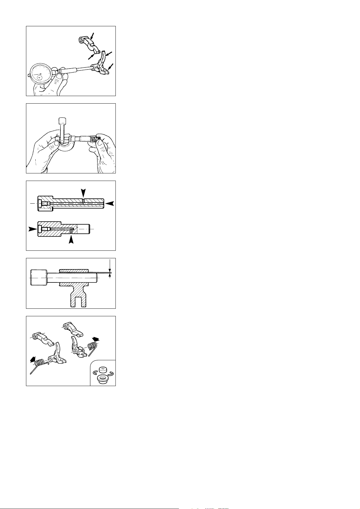
BILANCIERI
ROCKER ARMS
Controllare che le superfici di lavoro
siano in perfette condizioni, senza
tracce di usura, solchi o distacchi del
riporto di cromo. Controllare le
condizioni del foro del bilanciere e
quelle del relativo perno.
●
Gioco di accoppiamento al
montaggio:
0,030
÷
0,061 mm.
Limite di usura:
0,08 mm.
Pulire i canali di passaggio olio nei
perni bilanciere con scovolino e aria
compressa.
Check that the work surfaces of the
rocker arms are in good condition,
without any signs of wear, scoring or
peeling of the chrome coating.
Check the condition of the hole in
the rocker arm and the pin.
●
Assembly clearance:
0.030 -0.061 mm.
Wear limit:
0.08 mm.
Clean the oilways in the rocker arm
pins using a pipe cleaner brush and
compressed air.
REGISTRI DI APERTURA E
CHIUSURA - MOLLE
Verificare le condizioni delle superfici
di lavoro dei registri di chiusura e
apertura delle valvole: non devono
presentare tracce di usura.
Verificare le condizioni delle molle di
richiamo dei bilancieri di chiusura:
non devono presentare incrinature,
deformazioni o cedimenti.
70 Revisione motore / Engine overhaul
OPENING AND CLOSING
ADJUSTERS - SPRINGS
Check the work surfaces of the valve
opening and closing adjusters. There
must be no signs of wear.
Check the closing rocker arm return
springs. The springs must not be
cracked, bent or show signs of
failure.
Page 71
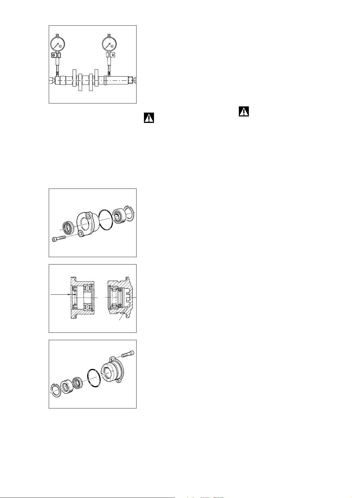
ALBERO A CAMME
CAMSHAFT
Controllare che le superfici di lavoro
delle camme siano prive di striature,
solchi, scalini o ondulazioni. Le
camme troppo usurate sono spesso
causa di una irregolare fasatura che
riduce la potenza del motore.
Inserire l’albero a camme tra due
contropunte e con comparatore
verificare la deviazione:
- Limite di usura:
0,05 mm.
Attenzione
Manipolare con estrema cura,
l’albero a cammes. Eventuali graffi o
anche impalpabili ammaccature
dovute ad urti, cadute dal banco,
ecc... possono infatti, pregiudicare il
rendimento del motore.
SUPPORTI ALBERO A CAMME
I supporti sono costituiti da una
fusione in lega leggera con all’interno
un anello seeger, un cuscinetto e un
paraolio. Verificare lo stato di usura
del cuscinetto e del paraolio (vedi
paragrafo “Sostituzione paraoli” e
“Cuscinetti” di questo capitolo).
Fare attenzione al posizionamento e
al verso di montaggio del paraolio
all’interno del supporto (vedi figura).
Lubrificare tutti i componenti prima
del rimontaggio.
Check that the work surfaces of the
cams are free of scratches, grooves,
steps and waving. Worn cams are
often the cause of irregular timing
and cause power losses.
Mount the cam shaft between two
centres and check the deviation
using two dial gauges:
- Wear limit:
0.05 mm.
Warning
Handle the camshafts with
great care. Possible dents,
scratching caused by shocks, falls
from the bench and so on may affect
operation and lead to severe engine
damage.
CAMSHAFT SUPPORTS
The camshaft supports consist of a
light-alloy casting housing a circlip, a
bearing and an oil seal. Check
bearing and oil seal for wear (see
“Changing oil seals” and “Bearings”
in this section).
When fitting the oil seal, ensure that
it is positioned correctly and facing
the correct way (as shown in the
drawing).
Lubricate all parts before refitting.
2 mm
Revisione motore / Engine overhaul 71
Page 72
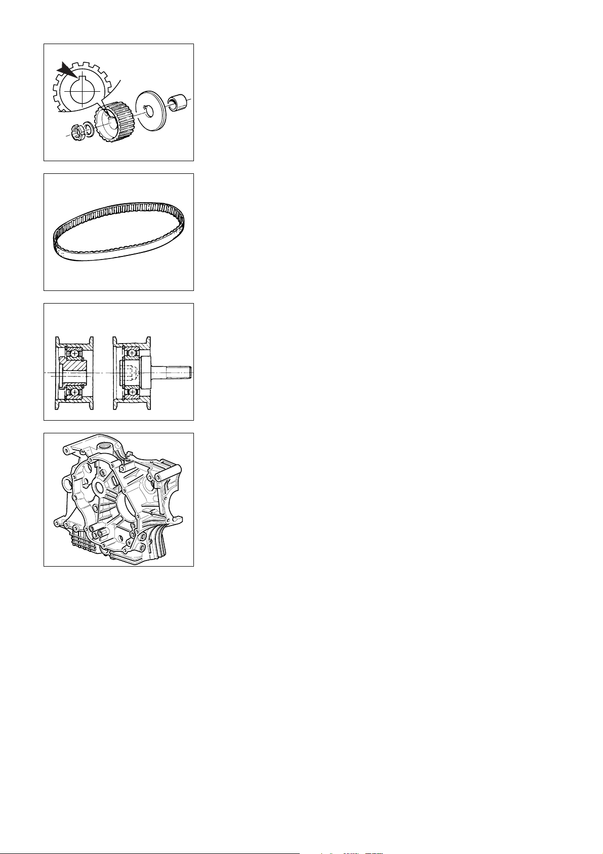
PULEGGE - CINGHIE TENDITORI
ROLLERS - BELTS TENSIONERS
Mobile
Mobile
Fisso
Fixed
Le pulegge della distribuzione non
devono presentare tracce di usura o
altri danni.
Verificare la sede della linguetta: non
deve risultare rovinata o impostata
dal contatto con la linguetta stessa.
Ad ogni rimontaggio sostituire
sempre la ghiera esterna e la rosetta
di bloccaggio puleggia.
Le cinghie devono essere in perfette
condizioni, senza screpolature, tagli o
deformazioni. È buona norma
sostituire le cinghie ad ogni
revisione del motore.
Ruotando la bussola esterna dei
tenditori, verificare lo stato di usura
del cuscinetto interno. Sostituire il
tenditore che presenti difficoltà di
rotazione o gioco eccessivo.
The timing rollers must not show
any signs of wear or damage of any
kind.
Check the keyway. It must not be
damaged or worn by contact with
the key.
At reassembly, change the outer
locking ring nut and washer on the
roller.
Belts must be in perfect condition
without cracks, cuts or kinks.
It is good working practice to
change the belts at each engine
overhaul.
Turn the outer bush of the
tensioners and check the wear of
the inner bearing. If the bearing
rotates with difficulty or shows
excessive play, change the
tensioner.
SEMICARTER MOTORE
Eliminare ogni traccia di sigillante.
Lavare accuratamente tutte le
canalizzazioni interne, eliminando
eventuali strozzature od ostruzioni;
asciugare con aria compressa quindi
procedere ad un accurato controllo
visivo dei semicarter.
Controllare, su di un piano di
riscontro, che le superfici di
accoppiamento siano perfettamente
piane. In caso contrario, applicare
sospensione diamantata (spessore
6
÷
12 micron) e ripassare la
superficie nel modo descritto la
paragrafo “Testa”.
Controllare che i cuscinetti siano in
ottimo stato. In caso di sostituzione,
seguire la procedura descritta al
paragrafo “Cuscinetti di banco”.
CRANKCASE HALVES
Clean off all signs of sealant.
Thoroughly flush out and clean the
oil ways removing any blockages or
obstructions and then dry with
compressed air.
Visually check the crankcase half.
Place the crankcase half on a
reference table and check that the
fastening surfaces are perfectly flat.
If the surfaces are uneven, grind
them with a grinding solution (6 - 12
micron) as described in the “Cylinder
Head” section.
Check that the bearings are in good
condition. To change the bearings,
follow the instructions given in the
section “Main bearings”.
72 Revisione motore / Engine overhaul
Page 73
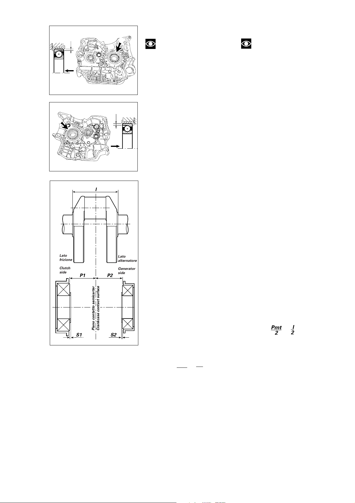
CUSCINETTI DI BANCO
,,,,@@@@ÀÀÀÀ,,,,@@@@ÀÀÀÀ,,,,yy
yy
,,,,@@@@ÀÀÀÀ,,,,@@@@ÀÀÀÀ,,,,yy
yy
MAIN BEARINGS
1
Lato
frizione
Clutch
side
K
1
Note
I cuscinetti di banco devono
sempre essere sostituiti in coppia e
devono essere installati nel giusto
1
verso nelle rispettive bussole dei
semicarter. Osservando il cuscinetto
riconoscere il lato (1) in cui lo
spessore (K) dell’anello esterno
risulta minore. Il cuscinetto dovrà
essere montato nella relativa bussola
mantenendo il lato (1) all’esterno.
Infatti, quest’ultimo, sarà il lato che
K
andrà poi in appoggio sull’albero
motore.
Note
Main bearings must always be
changed in pairs and must be fitted
in the right direction in the
respective crankcase half bushes.
Inspect the bearing to establish the
side (1) where the thickness (K) of
the outer ring is lower. The bearing
must be fitted in the corresponding
bush, keeping the side (1) on the
outside. This is the side which will
contact the crankshaft.
To change the bearings, proceed as
follows:
Per sostituire i cuscinetti è
1
necessario:
●
riscaldare il semicarter in forno
alla temperatura di 100°C;
❍
rimuovere il cuscinetto originale
mediante tampone e martello;
- installare il nuovo cuscinetto
(mentre il semicarter è ancora ad alta
I
temperatura) perfettamente in
quadro con l’asse dell’alloggiamento,
utilizzando un tampone tubolare che
eserciti la pressione solo sull’anello
●
Heat the crankcase half in an oven
to 100°C.
❍
Remove the old bearing using a
drift and a hammer.
- While the crankcase is still hot, fit
the new bearing squarely in its seat.
Use a tubular drift and ensure that
you only exert pressure on the outer
bearing ring.
- Allow the crankcase half to cool
down and then check that the
bearing is securely fixed in its bush.
esterno del cuscinetto;
- lasciare raffreddare il semicarter ed
accertarsi che il cuscinetto risulti
saldamente fissato nella relativa
bussola.
After fitting the new main bearings,
calculate the total shimming “S”
required using the following formula:
• S = P1+P2–l+Pmt
Where:
P1 = clutch-side crankcase depth
(inner ring)
P2 = chain-side crankcase depth
(inner ring)
l = distance between the contact
surfaces of the inner ring of the
crankshaft bearings.
Pmt = average theoretical preload
(0.20 mm).
To align the crankcase it will be
necessary to know the size of the
shims “S1” and “S2”. Calculate
these as follows:
• S1 = P1+ -
Pmt
• S2 = S–S1
I
2
2
Where:
S1 = clutch-side shimming
S2 = chain-side shimming
Spare sets of shims are available
with shims from 1.9 to 2.55 mm in
steps of 0.05 mm.
S1
P1
Piano contatto semicarter
Crankcase contact surface
P2
S2
Lato
alternatore
Generator
side
Dopo aver installato i cuscinetti di
banco nuovi applicare la seguente
formula per determinare la quota
“S” totale delle spessorazioni:
• S = P1+P2–l+Pmt
Dove:
P1 = profondità carter lato frizione
(anello interno)
P2 = profondità carter lato catena
(anello interno)
l = larghezza tra le superfici di
appoggio dell’anello interno dei
cuscinetti sull’albero motore
Pmt = precarico medio teorico
(0,20␣ mm).
Considerando l’allineamento
dell’albero, è necessario conoscere
l’entità delle singole spessorazioni
“S1” e “S2”.
• S1 = P1 + -
Pmt
• S2 = S–S1
_I_
Pmt/2
2
2
Dove:
S1 = spessorazione lato frizione
S2 = spessorazione lato catena
Sono disponibili a ricambio rasamenti
di spessore da 1,9 a 2,55 ad intervalli
di 0,05 mm.
Revisione motore / Engine overhaul 73
Page 74
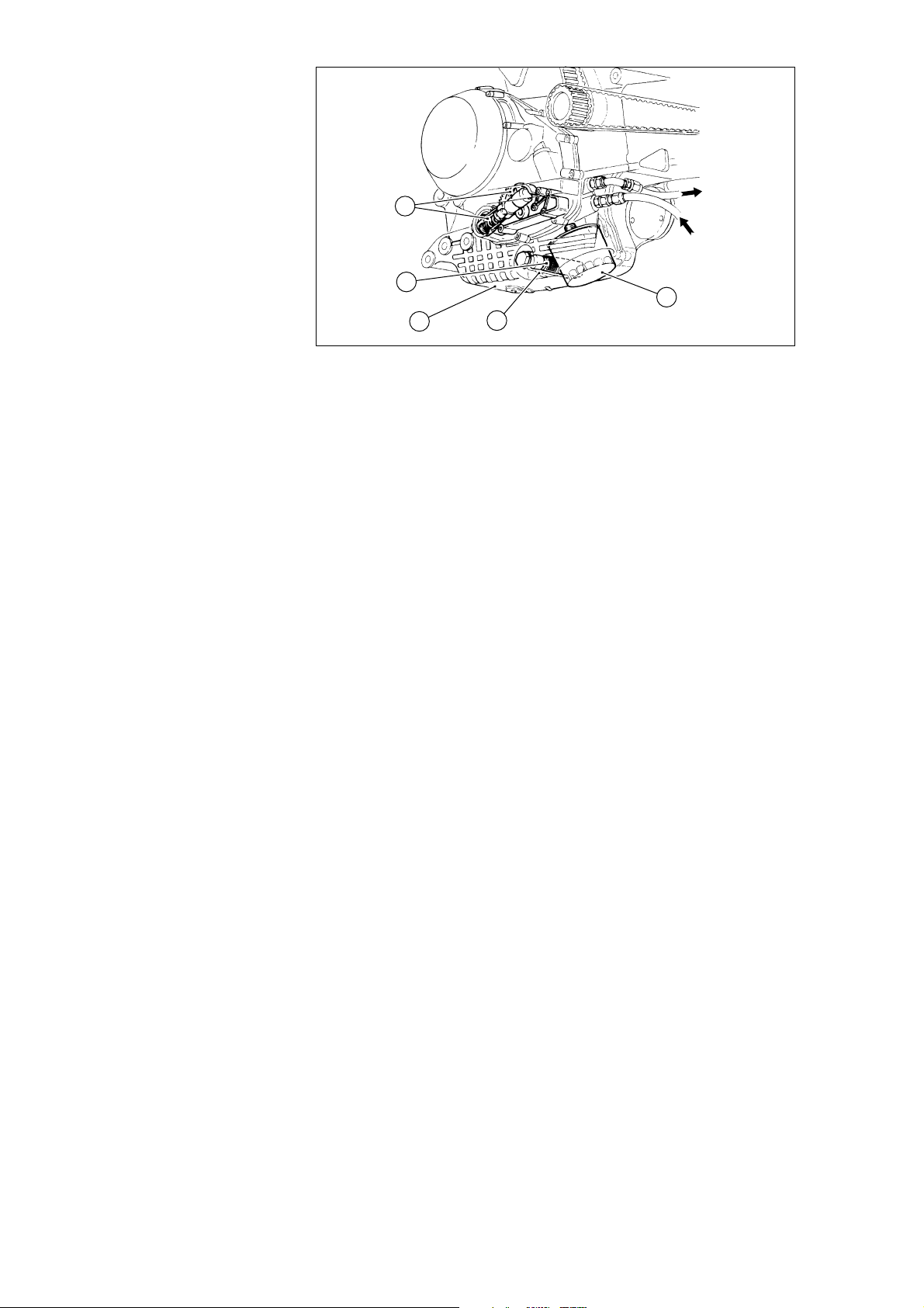
Al radiatore
4
To oil cooler
Dal radiatore
From oil cooler
2
1
3
CIRCUITO DI LUBRIFICAZIONE
l circuito di lubrificazione del motore
comprende:
1) Coppa olio
2) Filtro a rete
3) Tubo aspirazione
4) Pompa olio con valvola limitatrice
di pressione (by pass)
5) Filtro a cartuccia.
La pompa olio (4) è del tipo ad
ingranaggi con valvola by pass
incorporata e prende il moto, tramite
una coppia dentata, dall’albero
motore. La sua portata è quindi
funzione del regime di rotazione del
motore.
L’olio viene prelevato, tramite il filtro
a rete (2), solidale al fondo della
coppa olio (1).
Attraverso il filtro a rete (2), in grado
di trattenere eventuali impurità
grossolane, l’olio raggiunge la
pompa␣ (4). Al suo interno agisce una
valvola limitatrice che rimanda
l’eccedenza di olio in aspirazione in
caso di pressione eccessiva.
Dalla pompa, l’olio va verso il
radiatore attraverso un tubo flessibile
e all’ingresso radiatore stesso
prende due direzioni. Una parte va a
lubrificare le teste (olio non
raffreddato) per poi ricadere,
attraverso il cilindro, nel basamento.
L’altra parte attraversa il radiatore
raffreddandosi e successivamente
raggiunge il filtro a cartuccia␣ (5)
all’uscita del quale segue due circuiti:
- il primo, attraverso un particolare
getto, raffredda il cielo dei pistoni;
- il secondo, passando attraverso un
condotto del coperchio frizione, porta
l’olio all’albero motore.
L’olio, passando in canali interni
all’albero motore, lubrifica i
semicuscinetti della testa di biella e il
cuscinetto a rullini posto tra l’anello
doppio diametro e la ruota dentata
condotta dell’avviamento elettrico.
Una volta uscito dal circuito in
pressione e lubrificati gli organi
descritti, nel ricadere nel basamento,
lubrifica la trasmissione primaria,
5
LUBRICATION CIRCUIT
Engine lubrication circuit
1) Oil sump
2) Mesh filter
3) Intake pipe
4) Oil pump with pressure reducing
(by-pass) valve
5) Cartridge filter.
The oil pump (4) is a gear type pump
incorporating a by-pass valve. The
pump is driven over a toothed gear
pair by the crankshaft. Pump flow
rate therefore depends on engine
speed.
The oil is picked up through a mesh
filter␣ (2) fixed to the bottom of the oil
sump (1).
The oil passes through a mesh
filter␣ (2) which holds back large
impurities and is fed to the pump (4).
Inside the pump a by-pass valve
returns any excess oil caused by
excessive pressure to the intake
end.
The oil flows, into a hose, from the
pump to the radiator. At the radiator
infeed the circuit divides into two
sections. One part of the circuit
takes the oil to the cylinder heads
where the oil then drops down
through the cylinder to the sump.
Note that the oil fed to the heads is
not cooled. The other part of the
circuit passes through the radiator,
where it is cooled down, and at this
point reaches the cartridge filter (5).
At the cartridge filter outlet the
circuit divides into two:
- the first circuit feeds oil to a jet
which cools the piston crown;
- the second circuit passes through a
duct in the clutch cover and feeds
the oil to the crankshaft.
The oil passes through the oilways in
the crankshaft and lubricates con-rod
big-end bearings and the needle
roller bearing placed between the
double-diameter ring and the driven
gear wheel.
After lubricating the parts described,
the oil leaves the pressurised circuit
and drops down into the crankcase
74 Revisione motore / Engine overhaul
Page 75
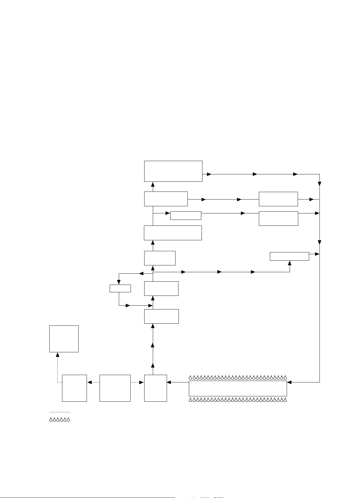
il cambio ed i cuscinetti di supporto
degli alberi cambio.
Il circuito di sfiato dei vapori che
vengono a crearsi all’interno del
basamento comprende una valvola
lamellare posta alla fine di un
condotto, prima dell’air box. In
questo modo, il lungo percorso,
permette ai vapori di olio di
ricondensare e ritornare nel
basamento.
where it lubricates the primary drive
gears, the gearbox and the gearbox
shaft bearings.
The oil breather pipe for the oil
fumes created inside the crankcase
has a reed valve positioned just
before the air box. Given the length
of the breather circuit, the oil fumes
condense in the breather pipe and
return to the crankcase.
by-pass
SCHEMA DI LUBRIFICAZIONE
Cuscinetto rullini ruota
libera / Starter clutch
needle roller bearing
Albero motore /
Crankshaft
Getto / Jet
Filtro olio a cartuccia /
Oil filter cartridge
Radiatore /
Oil cooler
Pompa olio /
Oil pump
LUBRICATION CIRCUIT
DIAGRAM
Testa biella /
Con-rod head
Cielo pistoni /
pistons crown
Ritorno in coppa / Return to sump
Teste / Heads
Scatola
filtro aria /
Air filter
box
Valvola
sfiato /
Breather
valve
Filtro a rete /
Mesh filter
Serbatoio
recupero /
Recovery
tank
Coppa
olio /
Oil
sump
Cambio / Primaria / Cuscinetti
Gearbox / Primary drive / Bearings
Circuito sfiato e ricircolo / Breather and recirculation circuit
Lubrificazione a caduta e sbattimento / Splash and gravity lubrication
Revisione motore / Engine overhaul 75
Page 76
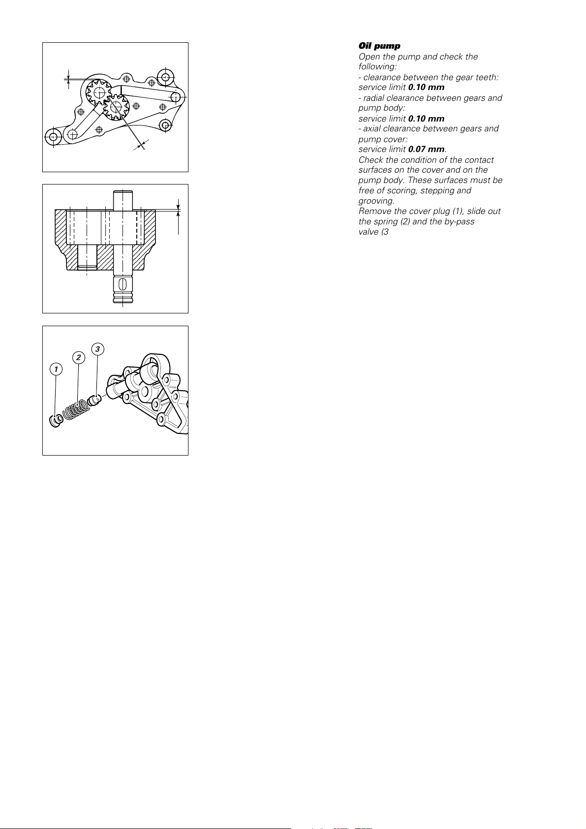
Pompa olio
Una volta aperta, procedere ai
seguenti controlli:
- gioco tra i denti degli ingranaggi:
limite di servizio 0,10 mm
- gioco radiale tra ingranaggi e corpo
pompa:
limite di servizio 0,10 mm
- gioco assiale tra ingranaggi e
coperchio:
limite di servizio 0,07 mm.
Verificare inoltre le condizioni delle
superfici di accoppiamento sul
coperchio e sul corpo pompa: non
devono presentare solchi, scalini o
rigature.
Rimuovere dal coperchio il tappo (1) e
sfilare molla (2) e valvola by␣ pass␣ (3).
Verificare le loro condizioni.
Lavare e soffiare con aria compressa
i canali interni.
Una volta riassemblata, riempire la
pompa con olio motore prima del
rimontaggio.
Oil pump
Open the pump and check the
following:
- clearance between the gear teeth:
service limit 0.10 mm
- radial clearance between gears and
pump body:
service limit 0.10 mm
- axial clearance between gears and
pump cover:
service limit 0.07 mm.
Check the condition of the contact
surfaces on the cover and on the
pump body. These surfaces must be
free of scoring, stepping and
grooving.
Remove the cover plug (1), slide out
the spring (2) and the by-pass
valve␣ (3).
Check the condition of these parts.
Wash out the oil ways and blow
through with compressed air.
Reassemble the pump. Fill the pump
with engine oil before refitting it to
the engine.
3
2
1
76 Revisione motore / Engine overhaul
Page 77
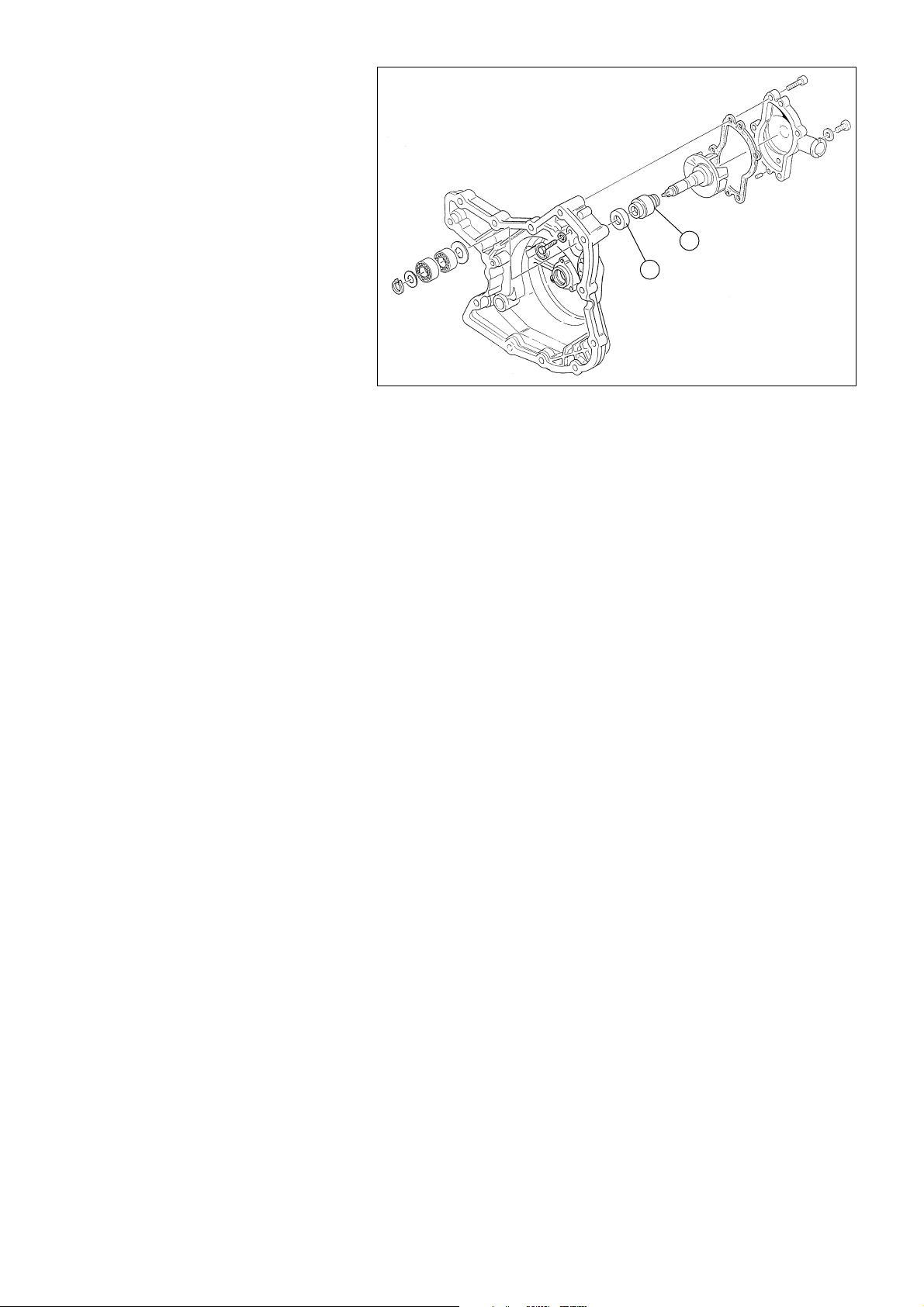
2
1
Pompa acqua
Pulire le canalizzazioni del coperchio
lato catena da eventuali incrostazioni
del liquido refrigerante. Verificare lo
stato di usura dei cuscinetti ruotando
lentamente la girante; in caso di
gioco eccessivo è necessario
rimuoverli operando come indicato
nella scomposizione motore.
Verificare le condizioni dei
componenti (1 e 2) della tenuta
meccanica: non devono apparire
deformazioni, incrinature o usura
eccessiva. In caso di danni, è
necessario sostituire entrambi i
componenti.
Water pump
Clean any coolant deposits from the
ducts in the chain-side cover. Turn
the pump rotor slowly to check for
play in the pump bearings. If the
bearings are excessively worn,
remove and change them as
described in “Engine Disassembly”.
Check the condition of the
mechanical seals (1 and 2); check for
cracks, excessive wear and
deformation. Change damaged
seals. Seals must be changed in
pairs.
Revisione motore / Engine overhaul 77
Page 78
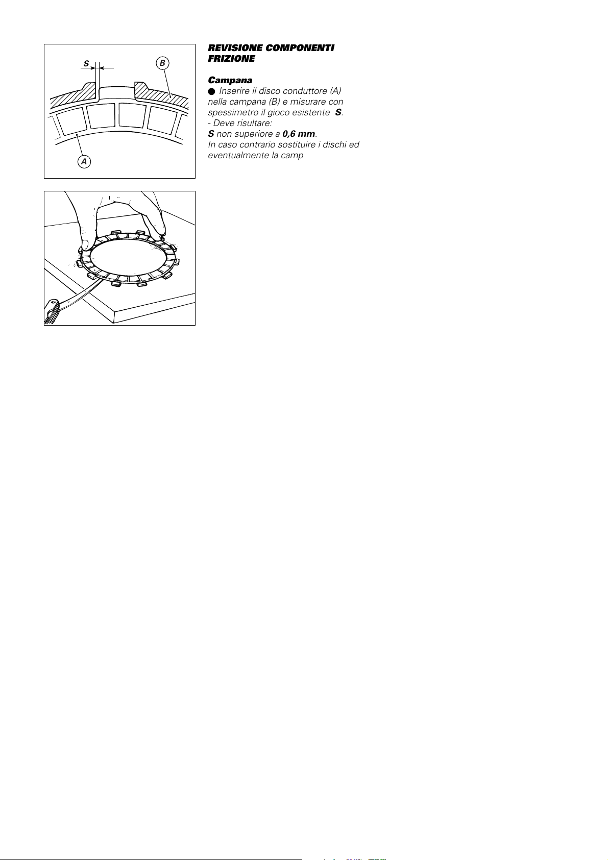
REVISIONE COMPONENTI
S
B
FRIZIONE
Campana
●
Inserire il disco conduttore (A)
nella campana (B) e misurare con
spessimetro il gioco esistente S.
- Deve risultare:
S non superiore a 0,6 mm.
In caso contrario sostituire i dischi ed
A
eventualmente la campana.
Verificare se la campana presenta
cricche o evidenti segni di
impostazione nel punto di appoggio
dei dischi conduttori.
CLUTCH OVERHAUL
Clutch housing
●
Insert the driving plate (A) in the
clutch housing (B) and use a feeler
gauge to measure the clearance S.
- Clearance :
S not greater than 0.6 mm.
If the clearance is greater than this,
change the plates and the clutch
housing.
Check the clutch housing for cracks
and heavy marking where the driving
plates rest against the clutch
housing.
Dischi
I dischi non devono presentare
tracce di bruciature, solchi o
deformazioni. Appoggiare il disco su
di un piano di riscontro e controllare
con uno spessimetro l’entità della
deformazione:
- Errore max. di planarità:
0,2 mm.
Per verificare l’usura dei dischi
conduttori è necessario misurare il
pacco composto da n
°
9 dischi.
- Spessore nominale:
22,5 mm (9x2,5 mm)
- Se risulta inferiore a 22 mm:
installare un disco da 2 mm (in
dotazione) in luogo di uno da 1,5 mm
- Se risulta inferiore a 21,5 mm:
installare n
°
2 dischi da 2 mm (in
dotazione) in luogo di due da 1,5 mm
- Se risulta inferiore a 21 mm:
sostituire il pacco dischi.
Clutch plates
Check the plates for scorching,
scoring and deformation. Place the
plate on a reference surface and
check the amount of deformation
with a feeler gauge:
- Max. flatness error:
0.2 mm.
To check the wear of the driving
plates, measure the thickness of a
pack of 9 plates.
- Nominal thickness:
22.5 mm (9x2.5 mm)
- If the pack is less than 22 mm
thick: fit a 2 mm-thick plate
(supplied) in place of the 1.5 mm
plate.
- If the pack is less than 21.5 mm
thick: fit two 2 mm-thick plates
(supplied) in place of the two
1.5 mm plates
- If the pack is less than 21 mm
thick: change the plate pack.
78 Revisione motore / Engine overhaul
Page 79
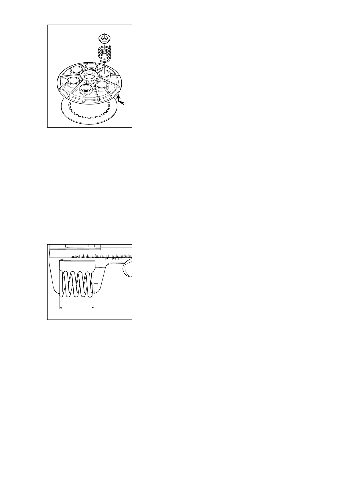
Piatto spingidisco
Verificare le condizioni del
cuscinetto: in caso presenti gioco
eccessivo, sostituirlo. Verificare la
superficie a contatto con l’ultimo
disco condotto; se risulta molto
segnata, procedere a levigatura
seguendo la procedura descritta per
il piano testa.
Sostituire sempre, ad ogni revisione,
gli scodellini di tenuta molla.
Pressure plate
Check the condition of the bearing;
change worn bearings. Check the
surface in contact with the last
driven plate. If the surface is very
scored, grind it smooth following the
same procedure as for the cylinder
head contact surfaces.
Change the spring caps at each
engine overhaul.
Molle
Misurare la lunghezza libera “L” di
ogni molla:
- Lunghezza minima:
39,75 mm.
Sostituire sempre ogni molla che
risulti inferiore a tale limite.
L
Springs
Measure the free length “L” of each
spring:
- Minimum length:
39.75 mm.
Change springs which are below this
measurement.
Revisione motore / Engine overhaul 79
Page 80
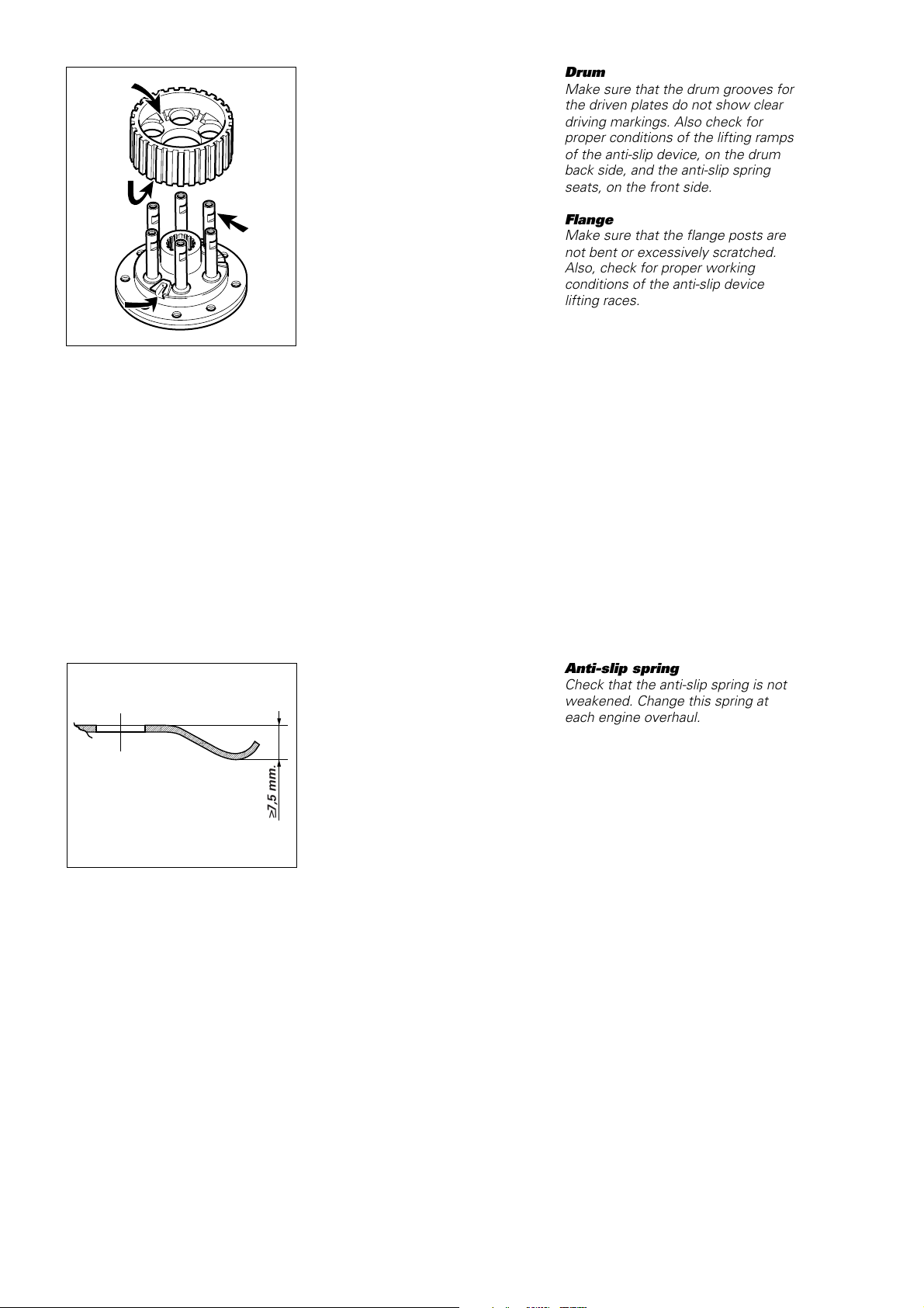
Tamburo
Controllare le scanalature dove
appoggiano i dischi condotti: non
devono presentare evidenti segni di
impostazione. Verificare inoltre le
condizioni delle rampe di salita del
dispositivo antisaltellamento, sulla
parete posteriore del tamburo, e
quelle delle sedi di lavoro delle
estremità della molla
antisaltellamento, sulla parete
frontale.
Flangia
Controllare le colonnette della
flangia: non devono risultare distorte
o eccessivamente segnate.
Verificare inoltre le condizioni delle
piste di salita del dispositivo
antisaltellamento.
Drum
Make sure that the drum grooves for
the driven plates do not show clear
driving markings. Also check for
proper conditions of the lifting ramps
of the anti-slip device, on the drum
back side, and the anti-slip spring
seats, on the front side.
Flange
Make sure that the flange posts are
not bent or excessively scratched.
Also, check for proper working
conditions of the anti-slip device
lifting races.
Molla antisaltellamento
Verificare che la molla
antisaltellamento non risulti snervata.
È consigliabile sostituirla ad ogni
revisione del motore.
7,5 mm.
≥
Anti-slip spring
Check that the anti-slip spring is not
weakened. Change this spring at
each engine overhaul.
80 Revisione motore / Engine overhaul
Page 81

Anomalie
Riportiamo di seguito un elenco di
cause che possono determinare un
malfunzionamento della frizione o del
dispositivo di disinnesto.
Una frizione che non stacca può
dipendere da:
- eccessivo gioco della leva di
comando;
- dischi frizione distorti;
- irregolare carico delle molle;
- difetto nel dispositivo di disinnesto;
- eccessiva usura del mozzo o della
campana.
Una frizione che slitta può dipendere
da:
- mancanza di gioco sulla leva di
comando;
- dischi frizione usurati;
- molle snervate;
- difetto nel dispositivo di disinnesto;
- eccessiva usura del mozzo o della
campana.
Una frizione rumorosa può
dipendere da:
- eccessivo gioco tra gli ingranaggi
della trasmissione primaria;
- denti degli ingranaggi della
trasmissione primaria danneggiati;
- eccessivo gioco tra estremità dischi
conduttori e campana frizione;
- cuscinetti di supporto ingranaggio/
campana frizione usurati;
- presenza di particelle metalliche
(limatura) sui denti degli ingranaggi.
Clutch troubleshooting
This section describes clutch and
disengagement mechanism
malfunctions and some of their
possible causes.
The clutch will not disengage.
Causes:
- excessive play of the clutch lever;
- distorted clutch plates;
- uneven spring loading;
- faulty disengagement mechanism;
- excessive wear of the drum or
clutch housing.
The clutch slips. Causes:
- insufficient play of the clutch lever;
- worn clutch plates;
- weakened springs;
- faulty disengagement mechanism;
- excessive wear of the drum or
clutch housing.
The clutch is noisy. Causes:
- excessive play between the
primary drive gears;
- damaged primary drive gear teeth;
- excessive clearance between
driving plate tangs and clutch
housing slots;
- worn clutch cover/gear bearing;
- filings and metal particles on gear
teeth.
Revisione motore / Engine overhaul 81
Page 82
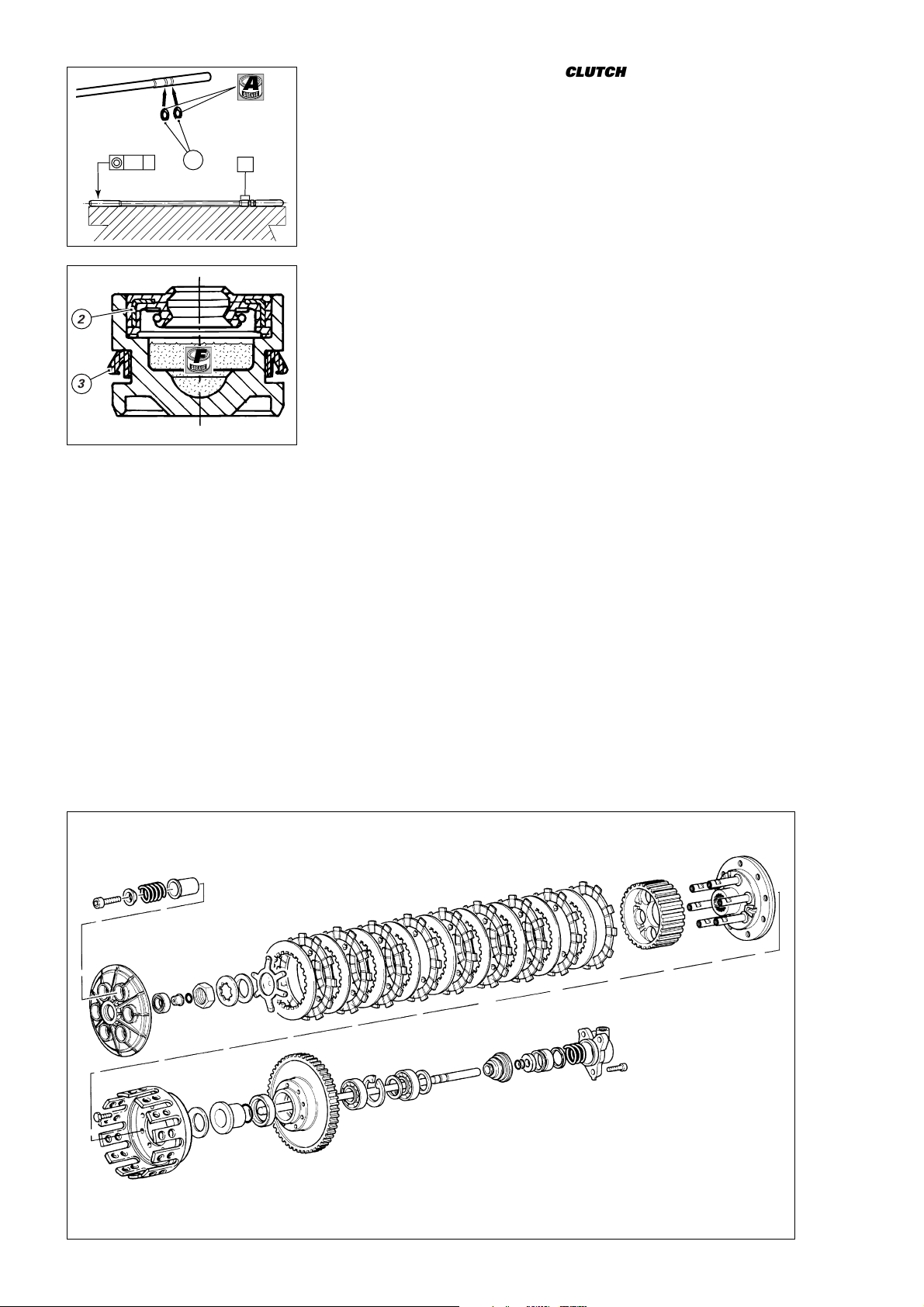
GRUPPO DI RINVIO FRIZIONE
CLUTCH TRANSMISSION UNIT
A
Verificare la concentricità dei due
diametri (indicati in figura) sull’asta di
comando frizione. Sostituire sempre
0.5 A
2
1
A
F
3
gli anelli OR (1) ad ogni rimontaggio
e lubrificarli con grasso.
Dopo aver rimosso il pistoncino dal
coperchio, verificare lo stato di usura
del paraolio interno (2) e del
raschiaolio esterno (3). Sostituire
sempre queste guarnizioni ad ogni
revisione del motore.
Nel rimontaggio, fare attenzione
all’orientamento delle guarnizioni di
tenuta posizionandole, dopo averle
lubrificate con olio motore, come
indicato in sezione. Riempire poi con
grasso la cava interna del pistoncino.
Check for proper concentricity of the
two diameters (shown in the
drawing) on the clutch pushrod.
Always change the O-rings (1) when
reassembling and grease. Remove
the cover piston and check the inner
oil seal (2) and outer oil scraper (3)
for wear. Always change these seals
when overhauling the engine.
At reassembly, lubricate the seals
with engine oil and position them as
shown in the cross section. Grease
the piston groove.
82 Revisione motore / Engine overhaul
Page 83
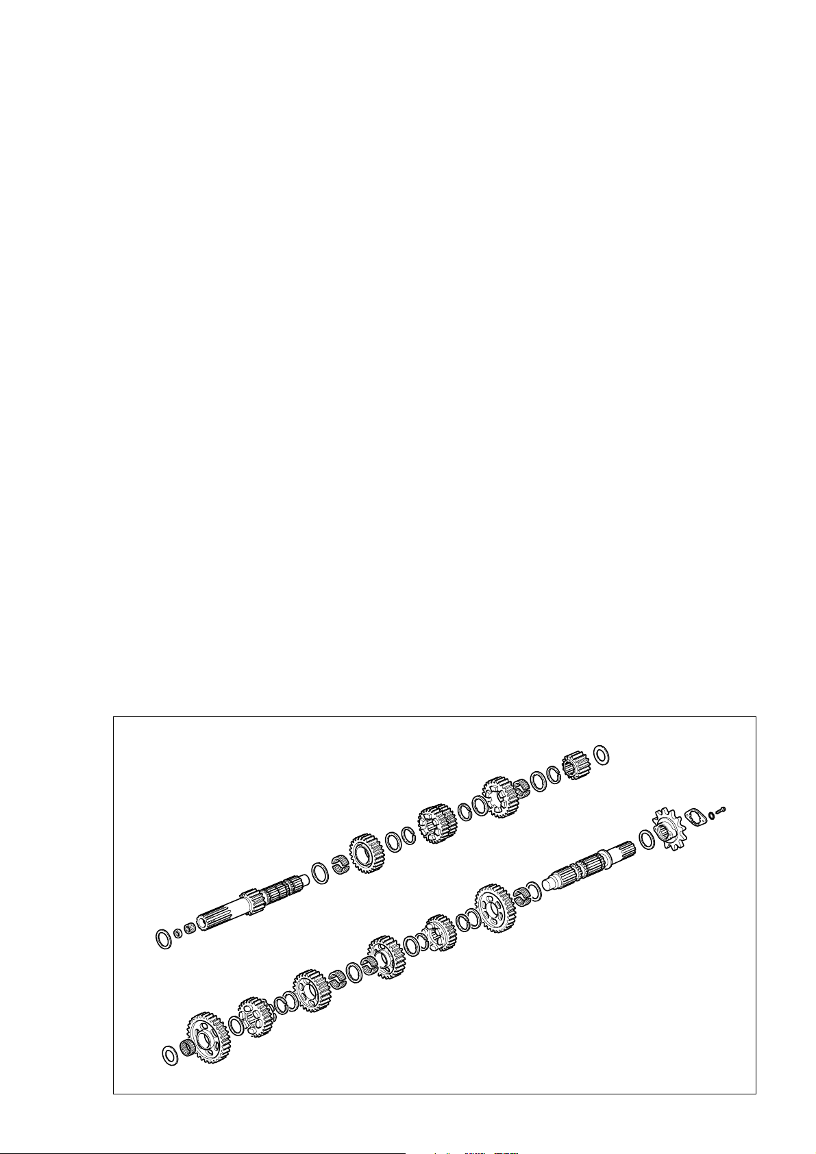
GRUPPO CAMBIO
GEARBOX
Controllare lo stato di usura degli
innesti frontali degli ingranaggi
conduttori.
Controllare le condizioni dei denti di
tutti gli ingranaggi cambio: non
devono presentare cricche o evidenti
segni di impostazione.
Verificare la scorrevolezza degli
ingranaggi folli sugli alberi.
In caso di smontaggio, verificare le
condizioni delle scanalature degli
alberi cambio.
Check the wear on the front of the
driving gear teeth.
Check the condition of the selector
gear teeth. There must be no signs
of cracks or forcing marks.
Check that the idling gears run
smoothly on the shafts.
If the gearbox has been
disassembled, check the condition of
the splines on the gearbox shafts.
Lato frizione
Clutch side
Lato catena
2ª
6ª
3ª
4ª
5ª
1ª
4ª
5ª
1ª
3ª
6ª
2ª
Chain side
Revisione motore / Engine overhaul 83
Page 84
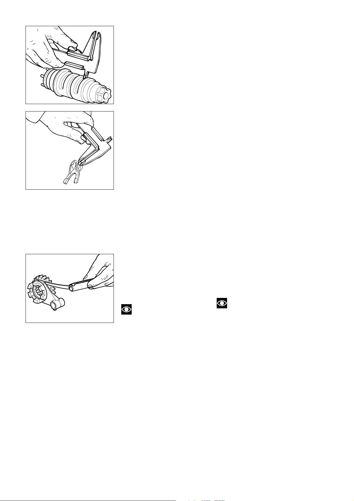
TAMBURO COMANDO
FORCELLE
- Controllare che la larghezza delle
cave del tamburo comando forcelle e
il diametro del perno sulla forcella
rientrino nelle tolleranze prescritte
dal costruttore.
●
Larghezza cava tamburo
nominale:
8,00
÷
8,09 mm
Limite di usura: 8,19 mm.
●
Diametro esterno nominale perno
forcella:
7,665
÷
7,735 mm
Limite di usura: 7,5 mm.
- Gioco nominale tra tamburo e
perno forcella:
0,265
÷
0,425 mm
Limite di usura: 0,6 mm.
Verificare lo stato dei perni di
supporto del tamburo: non devono
presentare solchi, bave o
deformazioni. Inserire e ruotare il
tamburo nelle sedi del semicarter e
valutare il gioco radiale presente: in
caso di gioco eccessivo sostituire il
componente più usurato.
SELECTOR DRUM
- Check that the width of the
grooves in the selector drum and the
fork pin diameter are within the
tolerances specified by the
manufacturer.
●
Drum groove nominal width:
8.00 -8.09 mm
Wear limit: 8.19 mm.
●
Fork pin nominal outer diameter:
7.665 -7.735 mm
Wear limit: 7.5 mm.
- Nominal clearance between drum
and fork pin:
0.265 - 0.425 mm
Wear limit: 0.6 mm.
Check the wear of the drum support
pins. They must be free of scoring,
burrs and bends. Insert the drum in
its seat in the crankcase half; rotate
the drum and check the radial play. If
the play is excessive, change the
part which is most worn.
FORCELLE SELEZIONE MARCE
- Ispezionare visivamente le forcelle
di selezione marce: il riporto di
cromo nella zona di lavoro
sull’ingranaggio deve risultare
integro.
Note
Ogni forcella che risulti piegata
deve essere sostituita in quanto può
causare difficoltà di innesto.
Controllare con uno spessimetro il
gioco di ogni forcella nella
scanalatura del proprio ingranaggio.
●
Gioco nominale tra pattino forcella
e scanalatura ingranaggio:
0,070
÷
0,285 mm
Limite di servizio 0,4 mm.
Verificare anche la rettilineità dei
perni di scorrimento delle forcelle
facendoli ruotare su di un piano di
riscontro.
- Controllare che la superficie sia
esente da solchi o scalinature.
GEAR SELECTOR FORKS
- Visually inspect the selector forks.
The chrome coating in the contact
area with the gear must be
undamaged.
Note
Bent forks will make gear
changing difficult and must therefore
be changed.
Using a feeler gauge, check the
clearance between the fork and the
spline of the gear it engages:
●
Nominal clearance between fork
slide and gear splining:
0.070 - 0.285 mm
Service limit 0.4 mm.
Roll the fork pins on a reference
surface and check their straightness.
- Check that there is no scoring or
stepping on the pin surface.
84 Revisione motore / Engine overhaul
Page 85
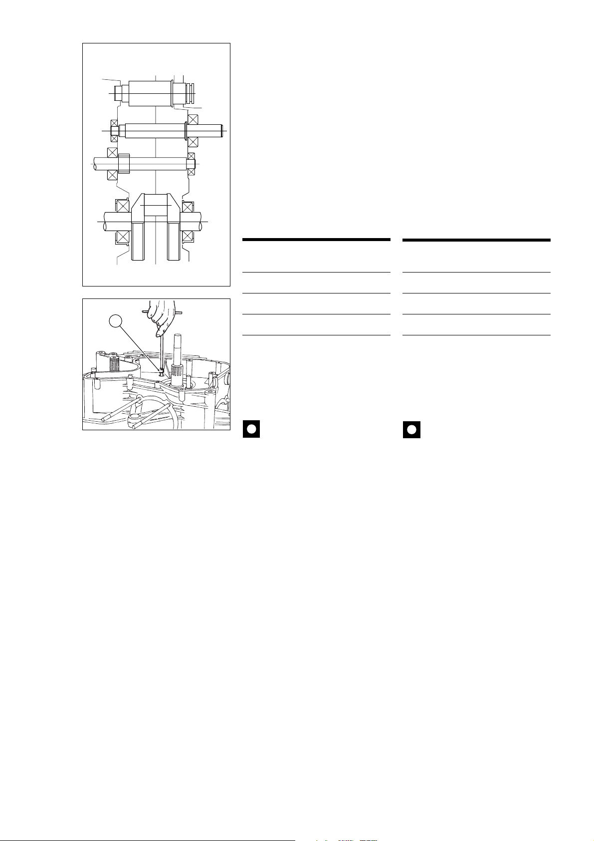
Lato frizione
Clutch side
1,0 mm
3,2 mm
1,1 mm
Tamburo com.
cambio
Gear selector
drum
Albero secondario
Layshaft
Albero primario
Mainshaft
Lato catena
Chain side
0,9 mm
0,9 mm
1,6 mm
SPESSORAZIONE ALBERI
CAMBIO E TAMBURO
COMANDO FORCELLE
●
Gioco assiale alberi cambio nel
basamento:
0,05
÷
0,15 mm.
●
Gioco assiale tamburo comando
forcelle nel basamento:
0,20
÷
0,30 mm.
In caso di montaggio di alberi cambio
e tamburo comando forcelle nuovi è
necessario determinare la corretta
spessorazione per ottenere il gioco
assiale prescritto. Per agevolare
l’operazione suggeriamo gli spessori
da montare come primo tentativo
(vedi figura).
SHIMMING THE GEARBOX
SHAFTS AND THE SELECTOR
DRUM
●
Axial clearance of the gearbox
shafts in the crankcase:
0.05 - 0.15 mm.
●
Axial clearance of the selector
drum in the crankcase:
0.20 - 0.30 mm.
When you fit new gearbox and
selector drum shafts it will be
necessary to recalculate the
shimming required to meet the
specified clearance.
As a first step, we recommend that
you fit the following shims (see the
drawing):
Alberi Lato Lato
frizione catena
Primario 1,1 mm 1,6 mm
Secondario 3,2 mm 0,9 mm
A
Tamburo 1 mm 0,9 mm
Procedere poi al montaggio degli
alberi cambio completi, del tamburo,
degli alberi guida e delle forcelle
seguendo le indicazioni riportate al
paragrafo “Chiusura semicarter” del
capitolo “RICOMPOSIZIONE”.
Importante
Quando si montano le viti di
fissaggio dei semicarter per
verificare la spessorazione, utilizzare
una vite di servizio al posto della vite
forata (A) in quanto quest’ultima è in
grado di resistere a 2 serraggi.
Shafts Clutch Chain
side side
Prim.shaft 1.1 mm 1.6 mm
Trans.shaft 3.2 mm 0.9 mm
Drum 1 mm 0.9 mm
Fit the complete gearbox shafts, the
selector drum and the guide shafts
and the forks following the
instructions given in “Closing the
crankcase halves” in the “ENGINE
REASSEMBLY” section.
Caution
When you fit the crankcase
halves to check the shimming, do
not use the drilled crankcase
retaining screw (A) as this type of
screw will only resist 2 tightening
operations. Use a service screw in
place of the screw␣ (A).
Se i giochi non sono in tolleranza
rimuovere gli alberi ed installare
rasamenti di spessore diverso.
Con gioco assiale degli alberi
corretto controllare , con cambio in
folle, che gli ingranaggi scorrevoli
risultino ben centrati rispetto a quelli
fissi. Verificare inoltre, innestando le
varie marce, che ci sia gioco tra
forcella e cava sull’ingranaggio. Se
così non risulta, mantenendo
inalterato lo spessore totale,
suddividere adeguatamente tale
quota tra lato frizione e lato catena.
If the clearances are not within
tolerance, remove the shafts and fit
shims of different sizes.
Continue until the correct axial play
is obtained. Next, with the gearbox
in neutral, check that the mobile
gears are perfectly centred on the
fixed gears. Engage gears and check
that there is sufficient play between
the selector fork and the slot on the
gear. If this is not the case, maintain
the same total shimming and divide
the shimming necessary between
the clutch side and the chain side.
Revisione motore / Engine overhaul 85
Page 86

86 Revisione motore / Engine overhaul
Page 87

Ricomposizione motore
Engine reassembly
Ricomposizione motore / Engine reassembly 87
Page 88

NORME GENERALI
GENERAL INSTRUCTIONS
Per il rimontaggio dei componenti
eseguire in senso inverso quanto
descritto per lo smontaggio,
prestando particolare attenzione alle
singole operazioni che verranno
descritte specificatamente in questo
capitolo.
Importante
Sostituire sempre
guarnizioni, paraolio, anelli di
arresto, rondelle in materiale
deformabile (rame, alluminio,
ecc...), dadi e ghiere autobloccanti.
I cuscinetti sono stati dimensionati e
calcolati per un determinato numero
di ore di lavoro. Consigliamo pertanto
la sostituzione in particolar modo dei
cuscinetti soggetti a più gravose
sollecitazioni, anche in
considerazione della difficoltà di
controllo della relativa usura.
Quanto sopra viene suggerito in
aggiunta ai controlli dimensionali dei
singoli componenti, descritti al
capitolo “REVISIONE MOTORE”, e
seguendo la tabella di manutenzione
riportata all’inizio del manuale.
È importantissimo pulire
accuratamente tutti i componenti; i
cuscinetti e tutti gli altri particolari
soggetti ad usura, dove non
diversamente specificato, dovranno
essere lubrificati con olio motore,
prima del montaggio.
Viti, dadi e ghiere dovranno essere
bloccati alle coppie di serraggio
prescritte, riportate in fondo al
manuale.
To reassemble the engine follow the
disassembly procedure in reverse
order by paying special attention to
the single operations described in
this section.
Caution
At reassembly change all
washers, oil seals, circlips,
washers in materials that may
deform - such as copper,
aluminium, etc. - nuts and selflocking ring nuts.
Bearings have been designed for a
specified number of working hours.
It is difficult to accurately check the
wear of bearings subject to
particularly heavy loading and these
bearings must therefore be changed
at reassembly.
When reassembling the engine,
follow the part checks specified in
“ENGINE OVERHAUL” and the
indications given in the maintenance
schedule at the front of this manual.
All components must be cleaned
thoroughly before refitting. TheIf not
otherwise specified, bearings and all
other parts subject to wear must be
lubricated with engine oil before they
are assembled.
Screws, nuts and ring nuts must be
tightened to the specified torque
values (refer to the table at the end
of this manual).
88 Ricomposizione motore / Engine reassembly
Page 89
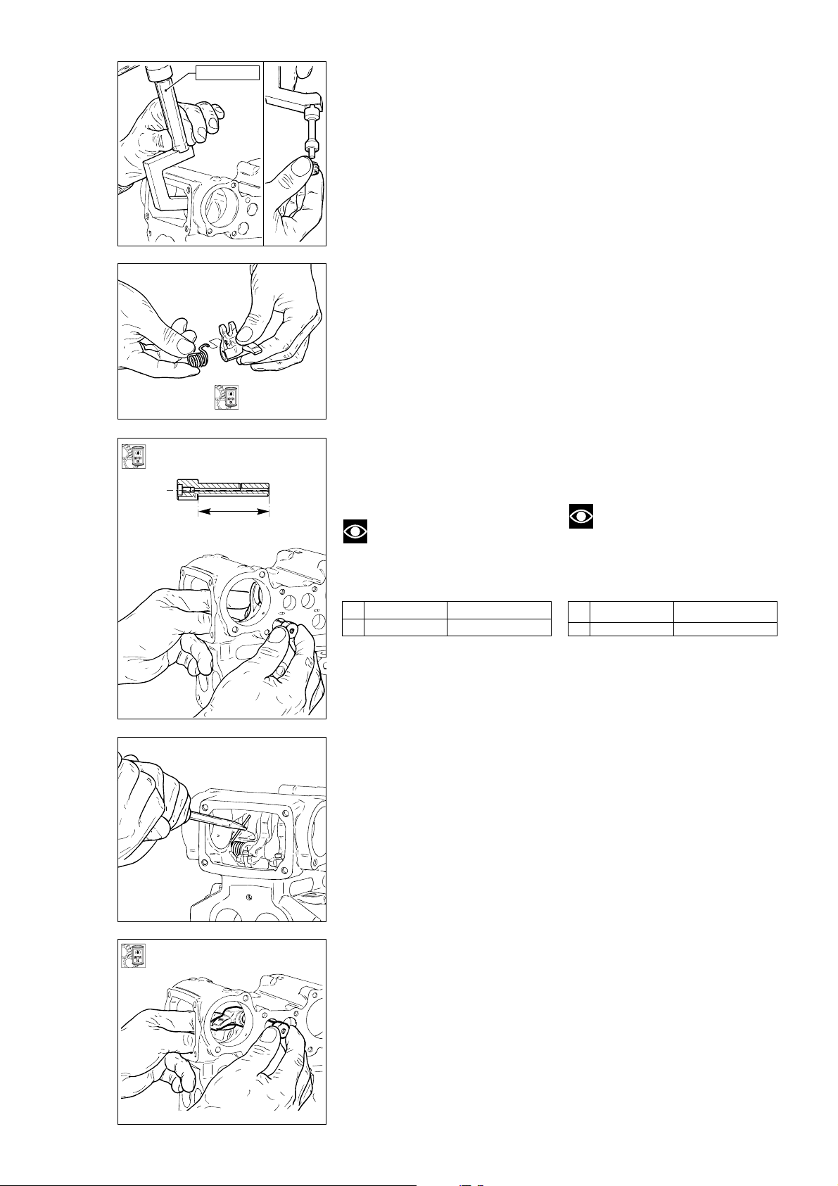
88713.1429
RICOMPOSIZIONE ORGANI
DELLA TESTA
REASSEMBLING CYLINDER
HEAD PARTS
- Sgrassare l’estremità del
guidavalvola quindi, dopo averlo
bagnato con alcool, posizionare
sull’attrezzo cod. 88713.1429 il
gommino di tenuta olio.
- Posizionare l’attrezzo in asse con il
guidavalvola ed inserirvi l’estremità
con anello di tenuta.
- Con un martello, battere
sull’estremità esterna dell’attrezzo e
portare a battuta l’anello di tenuta.
- Inserire l’estremità ripiegata della
molla nella sede del bilanciere
inferiore (di chiusura).
- Posizionare il gruppo mollabilanciere all’interno della testa, in
asse con il foro inferiore sede del
perno bilanciere.
- Dopo averlo lubrificato con olio
motore, inserire dall’esterno il perno
bilanciere e portarlo in battuta sulla
testa.
- Eseguire lo stesso procedimento
per montare l’altro bilanciere di
A
chiusura.
Nota
Fare attenzione a non
scambiare i perni di apertura (sono
- Degrease the end of the valve
guide. Soak the end of the valve
guide in alcohol.Fit the oil seal ring
on the service tool part no.
88713.1429.
- Align the service tool with the valve
guide and insert the end with the
seal ring into the guide.
- Using a hammer, knock the outer
end of the tool and drive the seal
ring fully home.
- Insert the curved end of the spring
into the seat on the closing (lower)
rocker arm.
- Position the rocker arm-spring
assembly inside the head so that it is
aligned with the lower hole which
acts as the rocker arm shaft seat.
- Lubricate the rocker arm shaft with
engine oil and then, working from
the outside, insert the shaft and
drive it fully home in the head.
- Follow the same procedure to fit
the other closing rocker arm.
Note
Be sure not to confuse the
shafts of the opening rocker arms they bear outer reference marks:
presenti marcature esterne):
Aspir. Scarico
A 30,35 mm 28,6 mm
- Con un cacciavite premere
sull’estremità rettilinea della molla,
sotto la sporgenza della testa.
Verificare, sollevando e rilasciando il
bilanciere, il corretto movimento di
ritorno.
- Inserire all'interno della testata, i
bilancieri di apertura.
Inserire il perno ben lubrificato con
olio motore dall'esterno.
Per evitare errori di montaggio questi
perni sono contrassegnati dalle
lettere A (aspirazione) e S (scarico).
Intake Exhaust
A 30,35 mm 28,6 mm
- Using a screwdriver, push the
straight end of the spring under the
jutting inside the head. Check the
spring return action by raising and
releasing the rocker arm.
- Fit the opening rocker arms into the
head. Insert the shaft duly lubricated
with engine oil from the outside.
Pins are punched with A (intake) and
S (exhaust) to avoid assembly errors.
Ricomposizione motore / Engine reassembly 89
Page 90
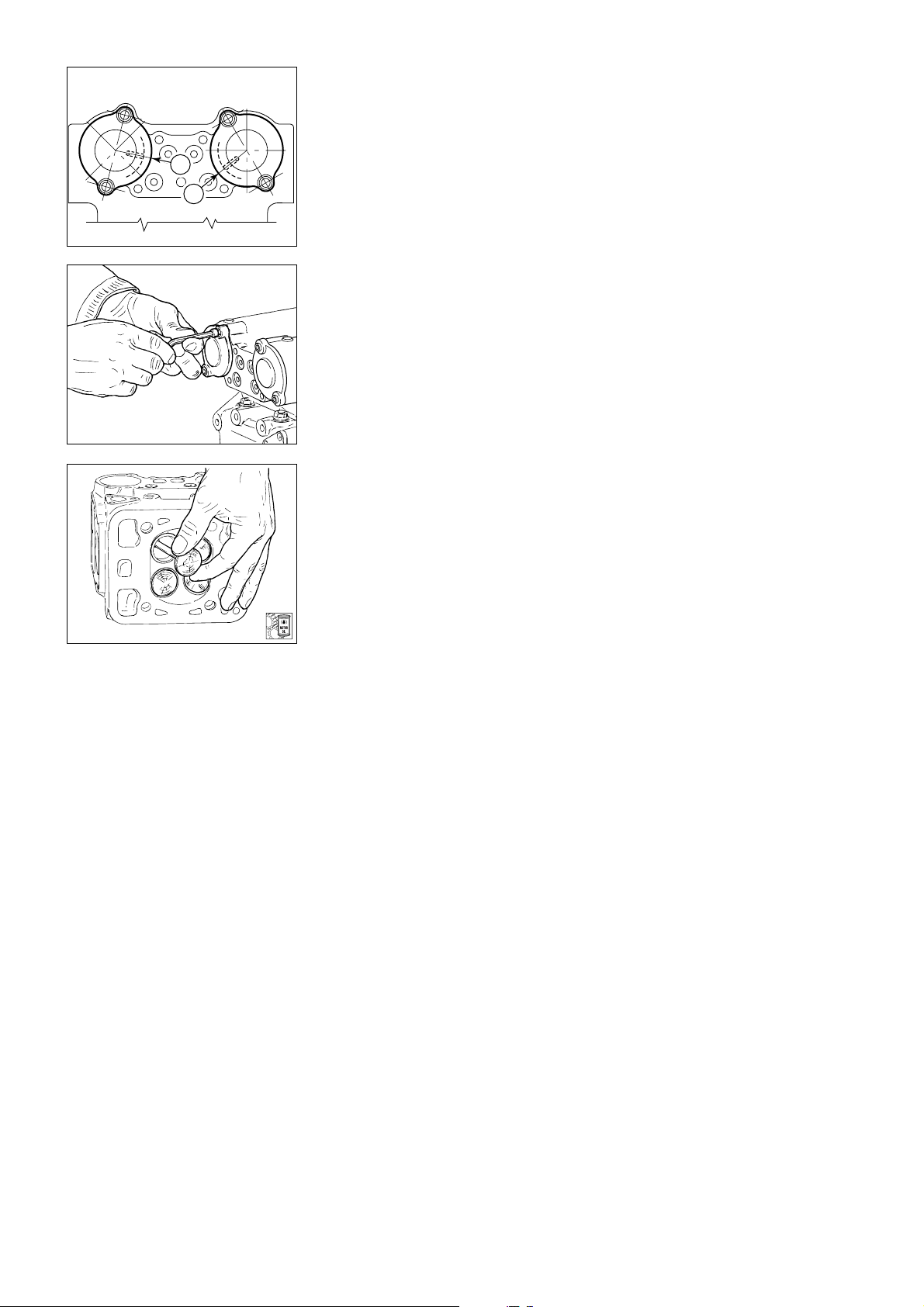
-
Verificare che all’interno del
cappellotto chiuso siano installati
l’anello di tenuta, il cuscinetto e
l’anello di arresto (vedi al paragrafo
“Supporti albero a camme” del
A
A
capitolo “Revisione motore”).
Lubrificare con olio motore i
componenti interni e con grasso la
sede della guarnizione OR.
▲
Montare la guarnizione OR
disponendola perfettamente nella
relativa sede quindi installare il
cappellotto sulla superficie della
testa, opposta al lato cinghie.
-
Orientare il cappellotto disponendo
il foro di passaggio olio (A) rivolto
verso l’interno.
-
Fissarlo alla testa con n° 2 viti
bloccate alla coppia prescritta.
▲
Montare allo stesso modo l’altro
- Check that the seal ring, the
bearing and the stop ring are fitted to
the camshaft closed support (see
“Camshaft supports” in “Engine
Overhaul”).
Lubricate the components inside the
support with engine oil and grease
the O-ring groove.
▲
Fit the O-ring squarely in its
groove. Fit the closed support to the
cylinder head side opposite the belt
side.
- Fit the closed support so that the
oilway (A) is facing inwards.
- Fix the closed support to the head
with the 2 screws and tighten to the
specified torque.
▲
Fit the other closed support in the
same way.
cappellotto.
Capovolgere la testa ed inserire le
valvole nei relativi guidavalvole
lubrificando abbondantemente con
olio motore l'accoppiamento.
Verificare il centraggio dello stelo
valvola rispetto alla forchetta del
bilanciere di chiusura, ed in caso di
decentraggio, usare, se possibile,
degli spessori, o provvedere alla
sostituzione del bilanciere.
REGISTRAZIONE DEI GIOCHI
●
Prima della spessorazione è
opportuno montare i coperchietti
laterali della testa, e le pulegge sugli
alberi a camme, al fine di non
compromettere i risultati.
●
Per questo motivo si consiglia di
seguire le istruzioni descritte a pag.
92 “Montaggio coperchietti laterali“
e 93.
Turn the head over and fit the valves
into their valve guides. Lubricate
with abundant engine oil.
Check valve stem centering with
respect to closing rocker arm fork. In
case of wrong centering, fit shims if
possible otherwise replace the
rocker arm.
ADJUSTING CLEARANCE
●
Fit head side covers and pulleys
onto camshafts before shimming for
optimal results.
●
Comply with instructions on page
92 “Assembling side covers” and
page 93.
90 Ricomposizione motore / Engine reassembly
Page 91
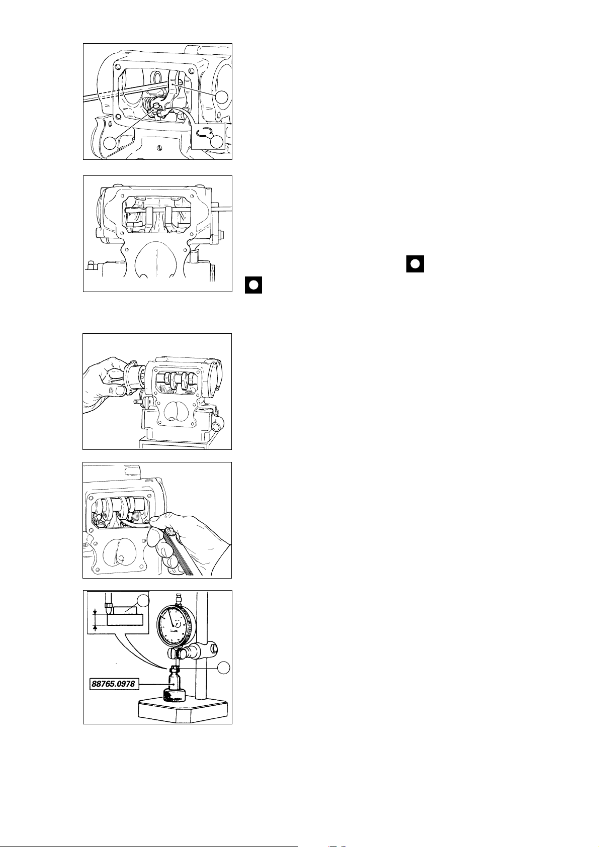
REGISTRI DI CHIUSURA
CLOSING SHIMS
- Alzare i bilancieri di apertura ed
abbassare quelli di chiusura
inserendo, con la dovuta cautela, un
1
giravite dall'apertura del supporto
albero a camme e facendolo passare
dietro ai pattini (1).
- Pulire accuratamente i registri di
2
3
chiusura (2), i semianelli (3).
Inserire gli scodellini di chiusura (2) e
i semianelli (3) sullo stelo delle
valvole. Eventualmente utilizzare un
leggero strato di grasso per
mantenere in posizione i semianelli
sulla valvola.
- Estrarre il giravite ed assicurarsi la
corretta posizione del registro e dei
semianelli, dopo aver battuto con un
- Lift the opening rocker arms and
lower the closing rocker arms. Insert
a screwdriver into the camshaft
support hole, behind the sliding
shoes (1) with the maximum care.
- Clean the closing shims (2) and the
split rings (3).
Insert the closing shims (2) and the
split rings (3) on the valve stem.
Apply a thin layer of grease to keep
the split rings in position on the
valve, if necessary.
- Remove the screwdriver and check
for proper installation of the shim
and split rings. Use an aluminium
tool to slightly beat the closing
sliding shoe.
leggero colpo sul pattino di chiusura,
con un battente in alluminio.
Caution
Always use new split rings.
Importante
Usare sempre semianelli
nuovi.
▲
Installare l'albero a camme
originale serrando il relativo
supporto.
Per facilitare la rotazione dell’albero
distribuzione è utile, durante la
procedura di spessorazione valvole,
installare con linguetta la puleggia
dentata, come già anticipato
precedentemente.
Con valvola in posizione di riposo
verificare con spessimetro, inserito
tra pattino bilanciere di chiusura e
camma, che il gioco di chiusura
risulti quello prescritto.
Se così non risulta, misurare
comunque il gioco presente. Ciò
consentirà di determinare la
differenza di spessore che sarà
necessario considerare per sostituire
lo scodellino di chiusura.
- Rimuovere il registro di chiusura e
controllarne lo spessore con
l’apposito calibro cod. 88765.0978 e
un comparatore inserito su di un
supporto a colonna.
1
- Azzerare il comparatore utilizzando
il blocchetto in dotazione all’attrezzo.
- Inserire il registro di chiusura (1)
sulla sommità del calibro (vedi
figura).
Misurare l’altezza della spalla del
registro di chiusura e scegliere quello
1
appropriato in base al valore rilevato
▲
Fit the original camshaft and
tighten its support.
For a smoother camshaft rotation,
install the toothed roller with the key
during valve shimming - as we told
before.
With the valve in its rest position,
make sure that the closing clearance
is as specified by inserting a feeler
gauge between closing rocker arm
sliding shoe and cam.
If the clearance is not as specified,
measure it for determining the shim
difference required when changing
the closing shim.
- Remove the closing shim and
measure it with gauge part no.
88765.0978; also fit a dial gauge
onto a stand support.
- Reset the dial gauge with the
supplied block.
Fit the closing shim (1) onto the
gauge top (see drawing).
Measure the height starting from the
shim shoulder and select the
required shim according to the
measured value.
▲
Fit the shim as previously
described and check for proper
closing clearance between cam and
rocker arm sliding shoe.
per ottenere il gioco prescritto.
▲
Rimontarlo come
precedentemente descritto e
verificare nuovamente il gioco di
chiusura tra camma e pattino
bilanciere.
Ricomposizione motore / Engine reassembly 91
Page 92
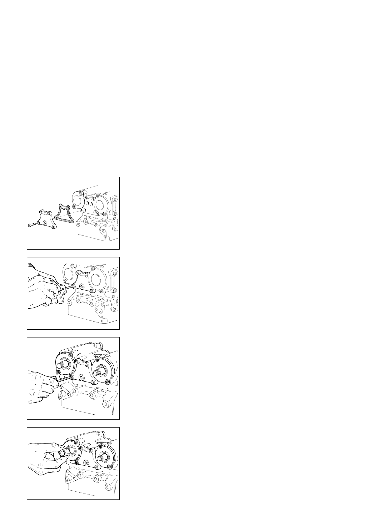
REGISTRI DI APERTURA
OPENING SHIMS
- Dopo la spessorazione del registro
di chiusura estrarre l'albero a
camme.
- Sollevare il bilanciere di apertura ed
inserire il registro di apertura
sull'estremità dello stelo valvola.
Inserire l'albero a camme con
attenzione e serrare i relativi
supporti.
- Portare l'albero a camme in
posizione di "riposo".
Inserire lo spessimetro tra il registro
ed il pattino del bilanciere di
apertura, facendo in modo che la
valvola non si muova.
- Ripetere l'operazione di
spessorazione come per il registro di
chiusura al fine di realizzare il gioco
desiderato.
MONTAGGIO COPERCHIETTI
LATERALI
- Installare la guarnizione metallica.
▲
Montare i coperchi su entrambi i
lati della testa, fissandoli con le
apposite viti bloccate alla coppia
prescritta.
❍
Rimuovere la puleggia e la
linguetta montati provvisoriamente
ed inserire il distanziale ben
lubrificato con olio motore
sull’estremità degli alberi a camme;
portarlo in battuta sull’anello interno
del cuscinetto di supporto.
- When finished with closing rocker
arm shimming, remove the
camshaft.
- Lift opening rocker arm and fit shim
at the valve stem end. Fit the
camshaft and tighten supports.
- Move the camshaft to its rest
position. Insert the feeler gauge
between shim and opening rocker
arm sliding shoe. Ensure that valve
does not move.
- Repeat shimming as described for
closing rocker arm.
ASSEMBLING SIDE COVERS
- Fit the metal gasket.
▲
Fit the cover on both head sides
by tightening the corresponfing
screws to the specified torque.
❍
Remove the roller, the key and fit
the shim duly lubricated with engine
oil onto the camshaft end. Drive it
fully home on the bearing inner ring.
92 Ricomposizione motore / Engine reassembly
Page 93
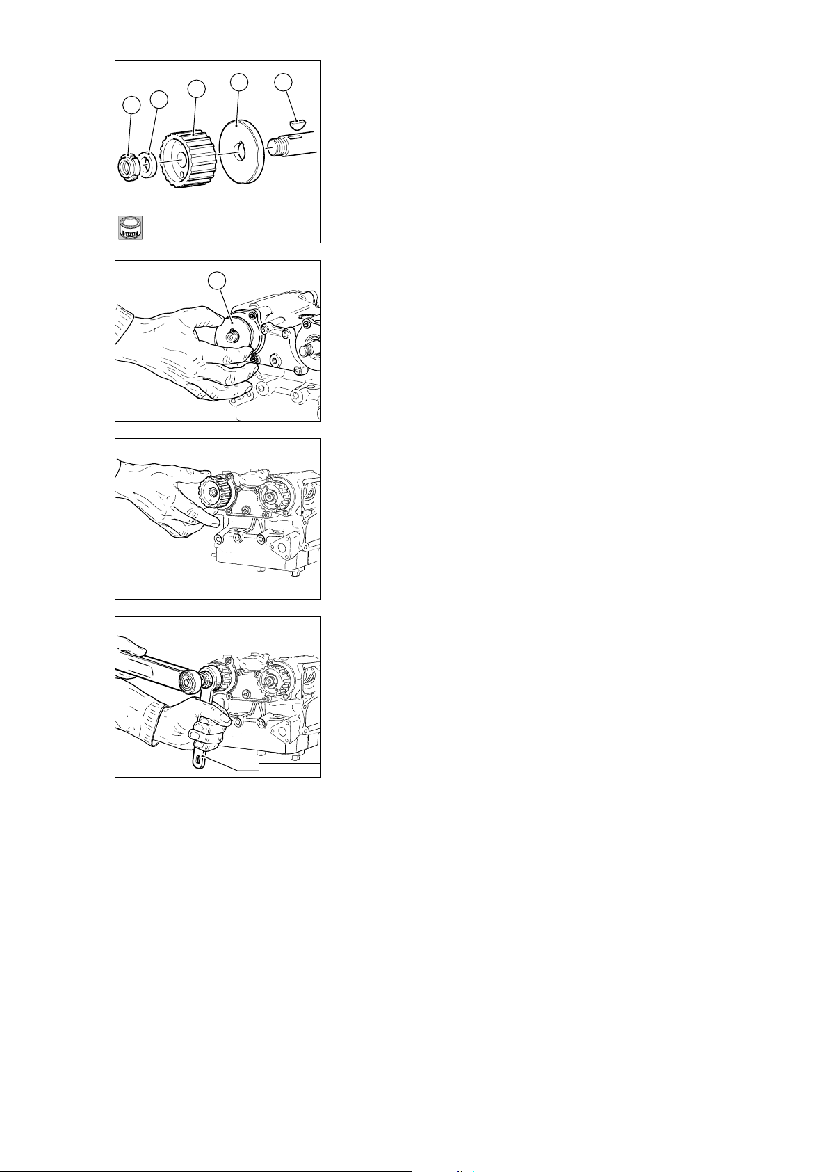
B
▲
Installare una linguetta (1) nuova
3
4
5
2 1
nella sede di ogni albero a camme e
inserire la rondella di appoggio (2)
per la puleggia distribuzione.
▲
Inserire la puleggia distribuzione
(3) con il punto bulinato per la
fasatura verso l'esterno, la rondella
di fermo nuova (4) e una ghiera
▲
Fit a new key (1) in the key way of
each camshaft. Fit the timing roller
support washer (2).
▲
Fit the timing roller (3) with timing
mark facing outwards, the new stop
washer (4) and a new locking ring
nut␣ (5). First grease both stop
surface and thread.
nuova di bloccaggio (5) dopo aver
ingrassato sia la battuta che il filetto.
- Clamp the roller in position using
the service tool part no. 88713.1932.
- Bloccare la puleggia utilizzando
l’attrezzo cod. 88713.1932 e serrare
2
la ghiera con una chiave
dinamometrica alla coppia prescritta.
Tighten the ring nut with a torque
wrench to the specified torque.
88713.1932
Ricomposizione motore / Engine reassembly 93
Page 94
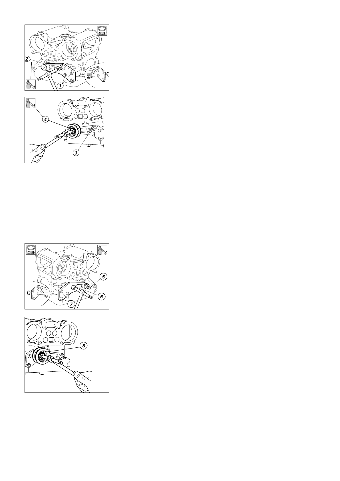
MONTAGGIO SUPPORTO
B
TENDITORI
ASSEMBLING TENSIONER
SUPPORT
2
LOCK
2
LOCK
Testa verticale
▲
Disporre nella sede
opportunamente ingrassata la
guarnizione OR e montare il
supporto tenditori sulla testa
impuntando le apposite viti (1).
▲
Dopo aver applicato il frenafiletti
impuntare la vite (2).
▲
Serrare le viti alla coppia
prescritta.
▲
Se precedentemente smontato
dal supporto, avvitare il perno
tenditore mobile (3) serrandolo alla
coppia prescritta, avvitando
successivamente anche il relativo
grano.
▲
Installare la bussola (4) tenditore
fisso nel supporto e sulla testa,
serrandola alla coppia prescritta,
dopo aver applicato il frenafiletti.
Vertical head
▲
Grease the seat and fit the O-ring.
Fit the tensioner support to the head
and start the corresponding screws
(1) in their holes.
▲
Apply threadlocker and start the
screw (2) in its hole.
▲
Tighten the screws to the
specified torque.
▲
If it was previously dismantled
from the support, screw the mobile
tensioner pin (3) and tighten to the
specified torque. Tighten the
corresponding nut.
▲
Insert the fixed tensioner bush (4)
in the support and the head. Tighten
to the specified torque.
B
2
LOCK
Testa orizzontale
▲
Preparare il distanziale tenditori,
fermando la guarnizione OR
opportunamente ingrassata nella
rispettiva sede.
▲
Montare il distanziale tenditori,
impuntando il perno tenditore mobile
(5) e la vite (6) dopo aver applicato il
frenafiletti.
▲
Impuntare le 3 viti (7).
▲
Serrare alla coppia prescritta il
perno tenditore mobile (5) e le viti (6
e 7).
▲
Montare il perno tenditore fisso
(8) con la corrispondente bussola.
▲
Serrare il granino di sicurezza.
Horizontal head
▲
Properly seat OR and then take
tensioner spacer.
▲
Install tensioner spacer and fit
mobile tensioner pin (5) and screw
(6) after applying proper thread
locker.
▲
Fit the three screws (7)
▲
Tighten mobile tensioner pin (5)
and screws (6 and 7) to specified
torques.
▲
Fit fixed tensioner pin (8) and its
bushing.
▲
Tighten safety grub screw.
94 Ricomposizione motore / Engine reassembly
Page 95
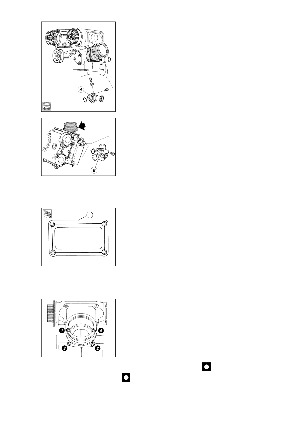
MONTAGGIO RACCORDO
USCITA ACQUA
ASSEMBLING WATER OUTLET
CONNECTOR
B
Testa verticale
▲
Disporre sul lato opposto al
supporto tenditori la guarnizione OR
nella sede opportunamente
ingrassata e posizionare il raccordo
(A) di uscita acqua, orientato come in
figura, impuntando le tre viti di
fissaggio.
- Serrare le viti alla coppia prescritta.
Testa orrizzontale
▲
Disporre sul lato opposto al
supporto tenditori la guarnizione OR
nella sede opportunamente
ingrassata e posizionare il raccordo
(B) di uscita acqua, orientato come in
figura, impuntando le tre viti di
fissaggio.
- Serrare le viti alla coppia prescritta.
Vertical head
▲
On the opposite side of the
tensioner support, grease the
connector seat and fit the O-ring.
Fit the water outlet connector (A) in
the position indicated in the
drawing.Start the three retaining
screws in their holes.
- Tighten the three retaining screws
to the specified torque.
Horizontal head
▲
Move round to the other side,
grease the connector seat and fit the
O-ring. Fit the water outlet connector
(B) in the position indicated in the
drawing. Start the three retaining
screws in their holes.
- Tighten the three retaining screws
to the specified torque.
COPERCHIO ASPIRAZIONE
C
▲
Sgrassare accuratamente le
superfici che andranno a contatto.
▲
Applicare sigillante sul
coperchietto (C) seguendo il
percorso indicato in figura.
▲
Applicare sigillante sul filetto delle
viti e fermare il coperchietto.
▲
Serrare le viti alla coppia
INTAKE COVER
▲
Carefully degrease mating
surfaces.
▲
Apply sealant onto cover (C) as
shown in the figure.
▲
Apply sealant to screw threadings
and secure the cover.
▲
Tighten the screws to specified
torque.
prescritta.
COLLETTORE DI ASPIRAZIONE
▲
Posizionare il collettore di
aspirazione ed impuntare le viti (1 e
2).
▲
Inserire le restanti viti (3 e 4)
avvitandole parzialmente.
▲
Portare a serraggio le viti nel
seguente ordine:
– 1 e 2, assicurandosi della
centratura delle superfici che
INTAKE MANIFOLD
▲
Position intake manifold and fit
the screws (1 and 2).
▲
Fit the remaining screws (3 and 4)
and tighten them partially.
▲
Tighten screws in the following
order:
– 1 and 2: ensure surfaces limiting
intake lines are properly centered;
– 3 and 4
definiscono i condotti di aspirazione;
– 3 e 4.
Caution
Fit intake manifold only after
Importante
Visto gli ingombri del collettore
fitting intake cover, as it is would be
in the way.
di aspirazione, questo può essere
montato solo dopo aver montato il
coperchietto di aspirazione.
Ricomposizione motore / Engine reassembly 95
Page 96

2
LOCK
4 5 6 7
CHIUSURA SEMICARTER
Se è stato rimosso durante lo
smontaggio, installare sul lato
esterno del semicarter lato frizione il
gruppo della levetta fermo marce.
Infilare sulla vite (4) la levetta (5) nel
verso raffigurato, la rosetta (6), e la
molla (7).
▲
Montare la molla (7) sul
semicarter, posizionandone
correttamente le estremità.
▲
Applicare frenafiletti sulla vite (4)
ed impuntarla.
▲
Bloccare la vite (4) alla coppia di
serraggio prescritta.
CLOSING THE CRANKCASE
HALVES
If the gear stop lever assembly was
removed previously, fit it to the
outside face of the clutch-side
crankcase half.
Slide the following parts onto the
screw (4): the lever (5) pointing in
the direction shown, the washer (6),
the spring (7).
▲
Fit the end of the spring (7) in the
correct position on the crankcase
▲
Apply threadlocker on the screw
(4) and start it in its hole.
▲
Tighten the screw (4) to the
specified torque.
96 Ricomposizione motore / Engine reassembly
Page 97
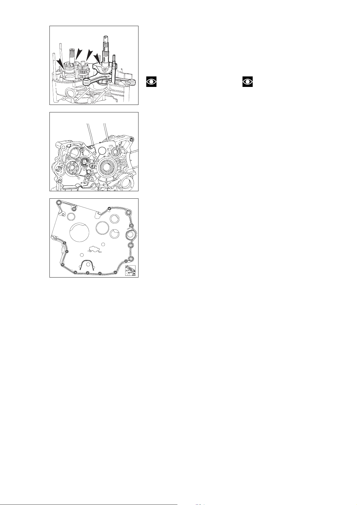
▲
Installare sull’albero motore, sugli
alberi cambio e sul tamburo selettore
i rasamenti stabiliti con la procedura
di spessorazione descritta al capitolo
“REVISIONE MOTORE” quindi
procedere al montaggio sul
semicarter lato frizione.
▲
Fit the shims calculated during the
shimming procedure described in
“ENGINE OVERHAUL” to the
crankshaft, the gearbox shafts and
the gear selector drum. Fit these
parts to the clutch-side crankcase
half.
Note
Quando si inserisce l’albero
motore nel semicarter accertarsi che
le bielle siano correttamente
posizionate nelle rispettive sedi dei
Note
When you insert the
crankshaft in the crankcase, ensure
that the con-rods are positioned in
the correct cylinder seats.
cilindri.
Installare l’albero rinvio distribuzione,
ben lubrificato, nel cuscinetto di
supporto del semicarter.
- Prima di inserire il gruppo cambio
nel semicarter, assicurarsi che la
B
pista interna (B) del cuscinetto albero
primario sia installata nel cuscinetto
e non sia rimasta montata
all’estremità dell’albero stesso.
- Analogamente anche per la pista
interna del cuscinetto albero
secondario sul semicarter lato
frizione.
▲
Installare i perni di guida e le
forcelle rifacendo invertite le
operazioni descritte nello
Lubricate and insert the timing
layshaft in the corresponding support
bearing in the crankcase half.
- Before you fit the gearbox
assembly to the crankcase half,
check that the internal race (B) of the
primary shaft bearing is attached to
the bearing and has not been left on
the end of the shaft.
- Make the same check on the
internal race of the ltransmission
shaft bearing in the clutch-side case
half.
▲
Fit the guide rods and selector
forks following the disassembly
procedure in reverse order.
smontaggio.
- Clean and degrease the crankcase
- Pulire e sgrassare le superfici di
accoppiamento dei semicarter quindi
applicare una guarnizione liquida sul
semicarter lato frizione, contornando
tutti i fori delle viti e delle boccole,
senza lasciare tratti scoperti che
half contact surfaces. Apply liquid
gasket on the clutch-side half. Apply
the sealant around the bolt holes and
bush seats. Do not leave any section
of the contact surface uncovered as
this will cause leaks later.
potrebbero provocare perdite di olio.
Ricomposizione motore / Engine reassembly 97
Page 98
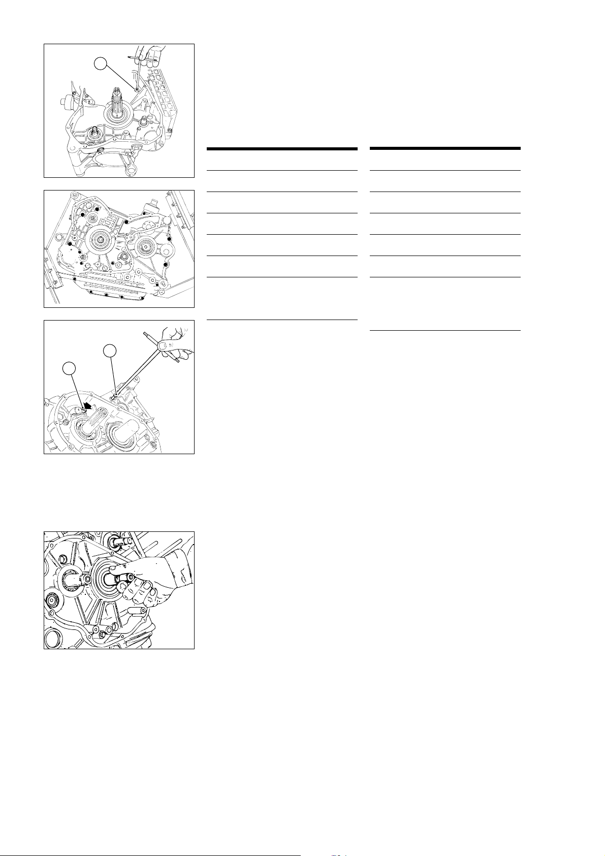
– Procedere all’inserimento delle viti
E
nelle rispettive sedi del semicarter
lato catena (vedi tabella).
– Serrare, partendo da quelle interne,
in modo progressivo tutte le viti alla
coppia prescritta.
Rovesciare il basamento ed installare
le 2 viti (F) dal lato frizione; bloccarle
alla coppia prescritta.
- Insert the screws into the seats on
the chain-side crankcase half (see
the table below).
- Start tightening from the inner
screws. Gradually tighten all the
screws to the specified torque.
Turn the crankcase cover and insert
the two screws (F) from the clutch
side; tighten to the specified torque.
rif. q.tà descrizione (mm)
A 2 viti TCEI M8x75
B 2 viti TCEI M8x90
F
B
B
C
C
D
D
D
D
C 2 viti TCEI M6x75
F
E
D
A
A
D
D
D 7 viti TCEI M6x35
E 1 vite TCEI M8x75
F 2 viti TCEI M6x80
(montate sul lato
frizione con rosetta)
Ref. Q.ty Description (mm)
A 2 M8x75 Allen screws
B 2 M8x90 Allen screws
C 2 M6x75 Allen screws
D 7 M6x35 Allen screws
E 1 M8x75 Allen screw
F 2 M6x80 Allen screws
(fitted on clutch
side with spring
washer)
F
F
- Controllare che l’albero motore
ruoti con una certa interferenza nei
cuscinetti di banco e assicurarsi che
tutti gli alberi e gli organi montati
ruotino o si spostino correttamente.
98 Ricomposizione motore / Engine reassembly
- Check that the crankshaft rotates
with a certain degree of interference
at the main bearings. Check that all
the shafts rotate and move correctly.
Page 99
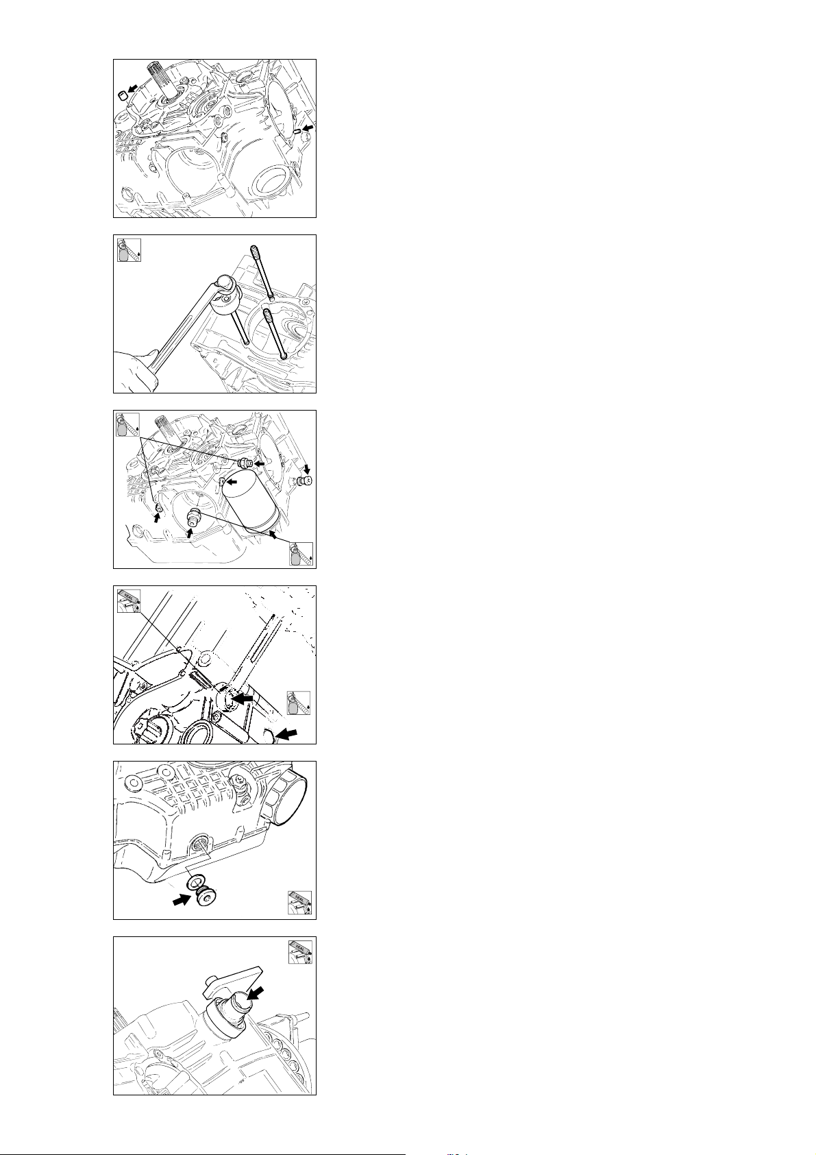
2
LOCK
2
LOCK
- Bloccare il filtro a rete quindi
procedere al rimontaggio dei
seguenti elementi, eseguendo
inversamente quanto descritto nello
smontaggio:
- grani centraggio cilindri
- boccole centraggio coperchi
- prigionieri
motorino avviamento: prima del
rimontaggio applicare sul filetto,
frenafiletti;
- nipplo supporto filtro olio: prima
del rimontaggio applicare sul filetto,
frenafiletti;
- nippli entrata e uscita olio per
radiatore: prima del rimontaggio
applicare sul filetto, frenafiletti;
- tappo per sede puntalino
posizionatore folle: prima del
rimontaggio applicare guarnizione
liquida;
- tappo per sede ex spia folle prima
del rimontaggio applicare frenafiletti
sul filetto del tappo;
- tappo scarico olio con relativa
guarnizione: prima del rimontaggio
applicare guarnizione liquida;
- raccordo di sfiato: prima del
rimontaggio applicare guarnizione
liquida sul filetto e sulla superficie di
contatto con il semicarter.
- Lock the mesh filter. Fit the
following parts as per the
disassembly procedure working in
reverse order.
- Cylinder centring locators.
- Cover centring bushes.
- Stud bolts.
Starter motor. Before assembly,
apply threadlocker to the thread.
- Oil filter support nipple. Before
assembly, apply threadlocker to the
thread.
- Oil cooler infeed and outfeed
nipples. Before assembly, apply
threadlocker to the thread.
- Plug for neutral gear stopper
seat. Before assembly, apply liquid
gasket.
- Plug for former neutral light hole.
Before assembly, apply thread locker
on the plug thread.
- Oil drain plug and seal. Before
assembly, apply liquid gasket.
- Oil breather connector: Before
assembly, apply liquid gasket on the
thread and on the contact surface
with the crankcase half.
2
LOCK
2
LOCK
Ricomposizione motore / Engine reassembly 99
Page 100
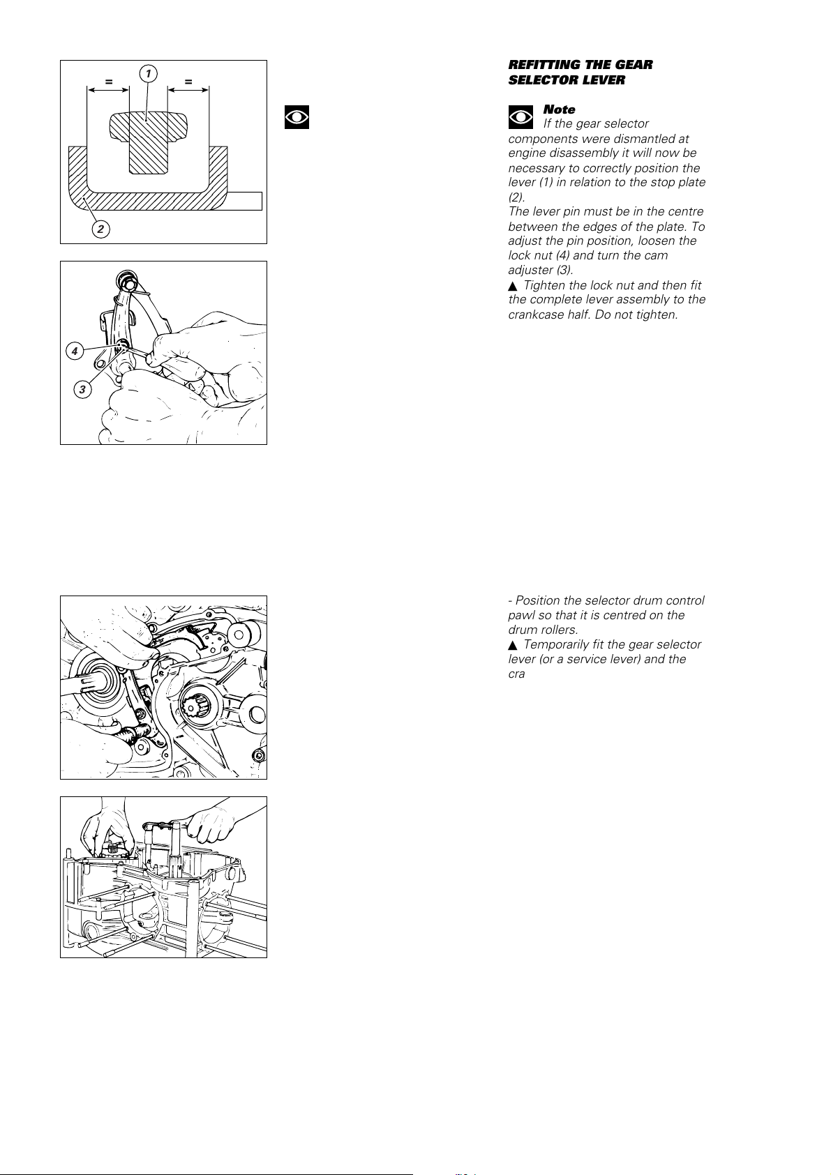
,,,,,,
,,,,,,
,,,,,,
@@@@@@
@@@@@@
@@@@@@
АААААА
АААААА
АААААА
,,,,,,
,,,,,,
,,,,,,
@@@@@@
@@@@@@
@@@@@@
АААААА
АААААА
АААААА
,,,,,,
,,,,,,
,,,,,,
yyyyyy
yyyyyy
yyyyyy
1
==
RIMONTAGGIO LEVERAGGIO
SELEZIONE MARCE
REFITTING THE GEAR
SELECTOR LEVER
Note
Se durante lo smontaggio si è
proceduto alla separazione dei
componenti del leveraggio di
selezione è necessario posizionare
correttamente la leva (1) rispetto alla
piastrina (2) di fine corsa.
Il perno della leva deve risultare
2
equidistante rispetto ai bordi della
piastrina; per modificare detta
posizione, agire sull’apposito perno
eccentrico (3) dopo aver allentato il
controdado (4).
▲
Serrare il controdado e montare il
leveraggio completo sul semicarter
Note
If the gear selector
components were dismantled at
engine disassembly it will now be
necessary to correctly position the
lever (1) in relation to the stop plate
(2).
The lever pin must be in the centre
between the edges of the plate. To
adjust the pin position, loosen the
lock nut (4) and turn the cam
adjuster (3).
▲
Tighten the lock nut and then fit
the complete lever assembly to the
crankcase half. Do not tighten.
con le apposite viti di fissaggio,
4
3
senza bloccarle.
- Posizionare l’arpione che sposta il
tamburo comando forcelle, centrato
rispetto ai rullini del tamburo.
▲
Montare provvisoriamente la leva
del cambio (o una leva di servizio) e il
pignone motore e mettere il cambio
in terza marcia.
- Position the selector drum control
pawl so that it is centred on the
drum rollers.
▲
Temporarily fit the gear selector
lever (or a service lever) and the
crankshaft sprocket. Select the third
speed.
100 Ricomposizione motore / Engine reassembly
 Loading...