

Ducati 250 GT 1965, 250 Monza 1965, 250 Mach 1 1965, 250 Mark 3 1965, 250 Scrambler 1965 Instructions For Use And Maintenance Manual
~n~_~'l~.~l~.f.~~.~,,~__
- ~¡~~~~~~l.~
~-~-
.~
j-,
;~ . '~I
.¡'¡.tj. J~
!,.r"
:~t~\:~
!rj~
,l,~
"';,1
'''.~
. :;~t)':
"~'.~
.. ',"'t;
',-"IJ.!;)"
. ':,,:';,'
,c;lr' \~
::: ,~L'i;~
.~.' '-~~~
':~l~
~:L.
j
'.
:,1:
'-,,",
:~(I\
" .,' ~
"-,~.
'. y'
~\
:tl'
..
'"
,
;'J~
.~:'
\
~
\
, . 9 .' ;,~:t~'t~~itŽ~~
~/påad!l-' -";:T:t~;ç:.t:~V~~~:i!t~.
.,... ";'. . 1 t d ',....., ..', / :',. '-',t:...;;~~...f..t;¿.~~.. ~;~
~lleqS':u.,e3p,alf~ahO; .~~?DsZ¿~d~
.' . :.;.....~. ....,...".,..:. ..1; ..,(:;f; 'r';:, '.~," ~,.;-ti'; ....:.,':ö
...... . ,,..... . . . '. d '. . . . .' '. ......'. '''''''ò "r '~"', ,,~"''' ~ii
s'sài'åÁ5äòlol .
~~.":'''~:''\~'~;~' ~ ':l";'"~~';;,~~,'r'~-I,,,.,,,'~~, :.... - '~r"'...l' .
~~ .. '.. I'''f~,,~j--!~ ",." ~. \;f l 1!,~;, ~~~\'.:: '. ~:). ,1:::: ~"~'
,.':;: 7¡'Ô~'iiâ:!l;JoisiQt"'L~ ;¡~~'~:l"~;~\'.~,'~:,:'~~'''';. ....
~~èlOlOV\.,.ll .lH38 :y..../;:~¡
....~:i
. ..
,,;..
~ ..,
't.
.. . i ..
i "::.:
.....
~./¡;(~.,~ ..:
'" .r. ,
" . , ~¡,.', c.
, .
~,,~~.
,
. ~'d;;~1~(r~~~r~rf¡~~iIJ~11
. ',-rl
~
.~~
-~
':1
-;
'.
.:.
. "....
'. .
~
. ,~~.;, ~~;
~ ,., '. ~..:'-i
..
i .
t~
......-...,
v
.
. ~..".;'~ ..
-j,i: .'..~~~:tt~~.~~;~
,
r":4"
'0' ."'..,.'1....
,..
,~ t.i~.UN.,I~;riN.iHd
.j
, ~_,-,__ _~41
ç' ':_.9 d s- -9/V 1/1 h,L 1J)l Wi
~ j
d.. b t "': " 9 0 G. : ~'. ~ ..""-A~'CJ? ;?A / b /11
.'~
~
~
:'il
,:~
.. -~'.'
...t
, '~
. ".:~
· ~ n , t '1). ',::,;,'
.;~.: l7-f tl.iJ
-; .,,, l7/1 t II .~
, ,
? "7b7~ ø ~-' -CI 1-t
? ~' l ." ~ ~ l"l? , 8 I
" $' ", · '1 ox"' I. -t , G .i~
J-,, _-r I .)
.... C1!." )
(~'- -he-f.-) "'t;.6--t1tP. t7M!~l
. 1M .tI:l t: nnf, (j J g. 7-. r ç; J lJ- n I: í
d_d_--l~':_.)¡,_f2P · J,. ~(.. /' ...,U(J(
o
"_,.1-"
'.'..,
:ileys-we:J peey .Ieiio pøøds _ 9
~ JL wd) ll CQ
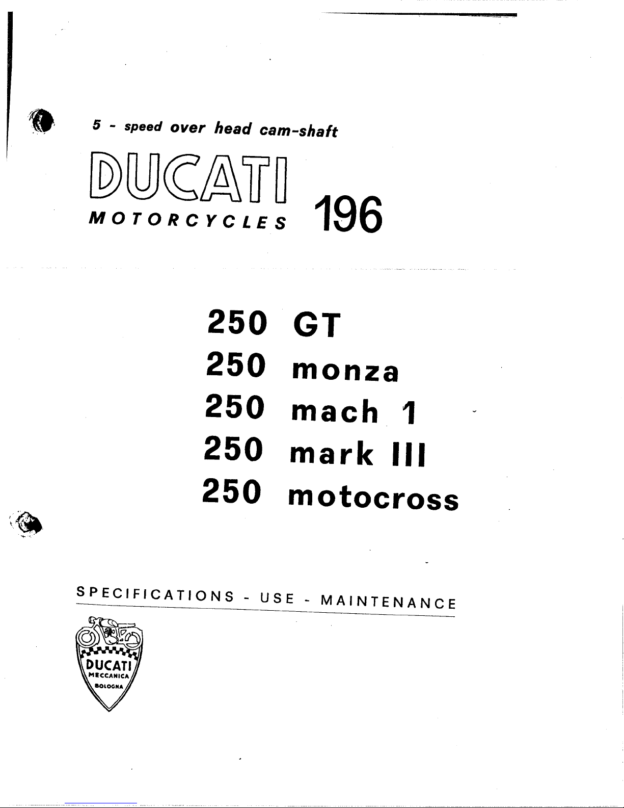
96L S37::A::lJO.LOW
l~ OSZ
ezuow OSZ
L Lf:iew OSZ
~/
'-l,\
;.-..
III lIJew OSZ
SSOJ:l°lOW OSZ
3~N\fN31NI\fl' - 3Sn - SNOI1\f~I:lI~3dS
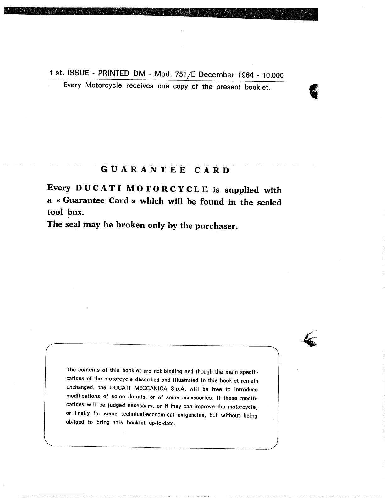
1 st. ISSUE - PRINTED DM - Mod. 751/E December 1964 - 10.000
Every Motorcycle receives one copy of the present booklet.
GUARANTEE CARD
Every D U CAT I MOT 0 R C Y C LEis supplied with
a (( Guarantee Card )) which will be found in the sealed
tool box.
The seal may be broken only by the purchaser.
4
(
The contents of this booklet are not binding and though the maIn specIfi-
cations of the motorcycle described and Illustrated in this booklet remain
unchanged. the DUCATI MECCANICA S,p,A, will be free to Introduce
modifications of some details. or of some accessories, If these modifi-
cations will be judged necessary, or if they can Improve the motorcycle,
or finally for some technical-economical exigencies. but without being
obliged to bring this booklet up-to-date.
~
~
\
~
I
~...-~~...-.. -:..:. 7...._ _~~..:.::"'~,':':_"',~.~ _'':_":_,,~ ,,:'~~ -:... ": .-"__"'~"":-:",-_,..._..........:~..__", :.
\(l
Dear Sir;
We are very glad to welcome you among our clients, and feel sure
that you will not fail to appreciate the magnificent performance
of the DUCATI Motorcycles.
I~,';,'
\~
The magnificent performance and reliability of our machines reo
fleet the experience gained throughout many years of successful
racing both on track and road.
In order to obtain the fine service that the Ducati machine is
capable of giving, it is essential that the instructions contained
in ' this book be religiously adhered to.
If ,these instructions are followed closely, particularly during the
running-in period of the machine then you will be assured 0f-
many years trouble-free enjoyable riding.
We thank your for your patronage and congratulate you on your
wise choice of such a fine machine with its unequalled perfor-
mance.
DUCATI MECCANICA S.p.A.
#'
~
-
LÐ osi IL v~na 3:'1~Å~1I0LOW
_ì
lf\
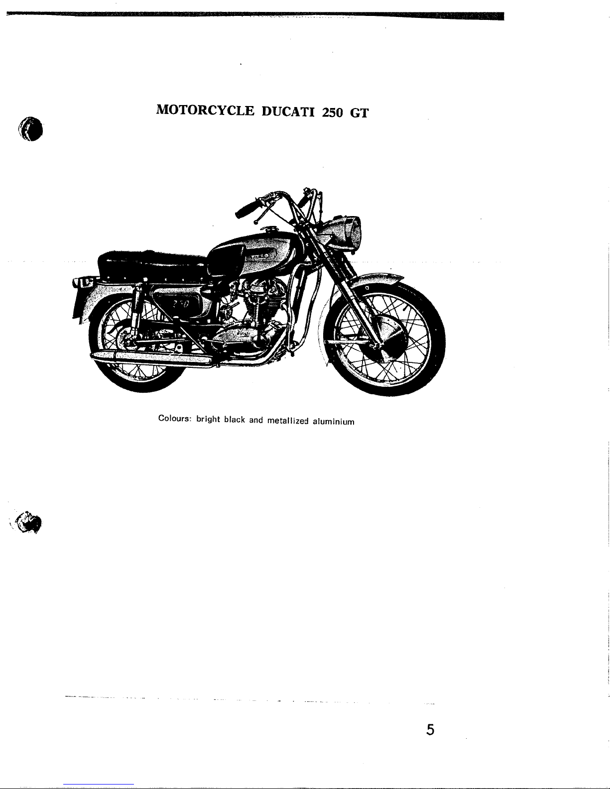
wn!u!wnie paz!iielaw pue )j3e1Q l4BpQ :s~noio::
ç
VZNOW osi iiV~na 3'1~Å~1I0iOW
l
9
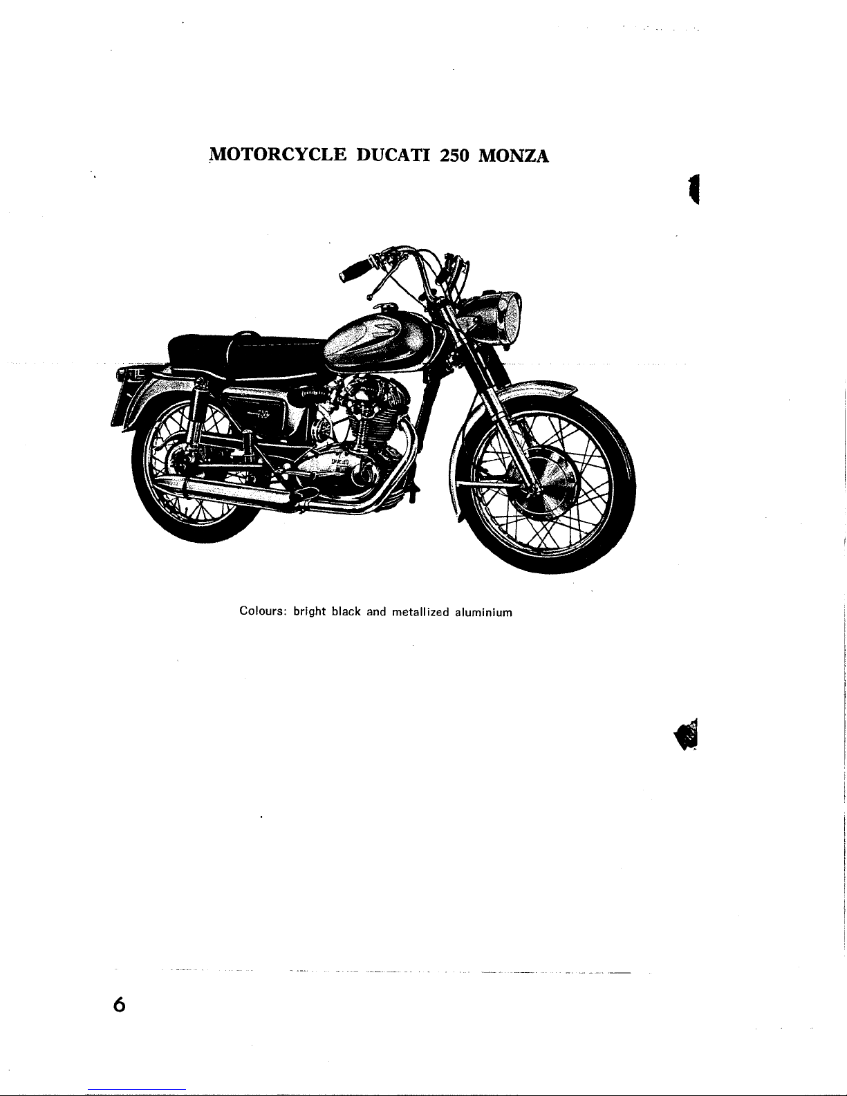
WnlU!wnle paz!liel3W pue )f:miq l4filJq :sJn0I0:J
.
....-.~-----,_.:.._....~:".;....:~:, ~_
r;
.,'11
I H3\iW OSZ ii \i3na 31:3Á3HOiOW
~lr:i
ii"
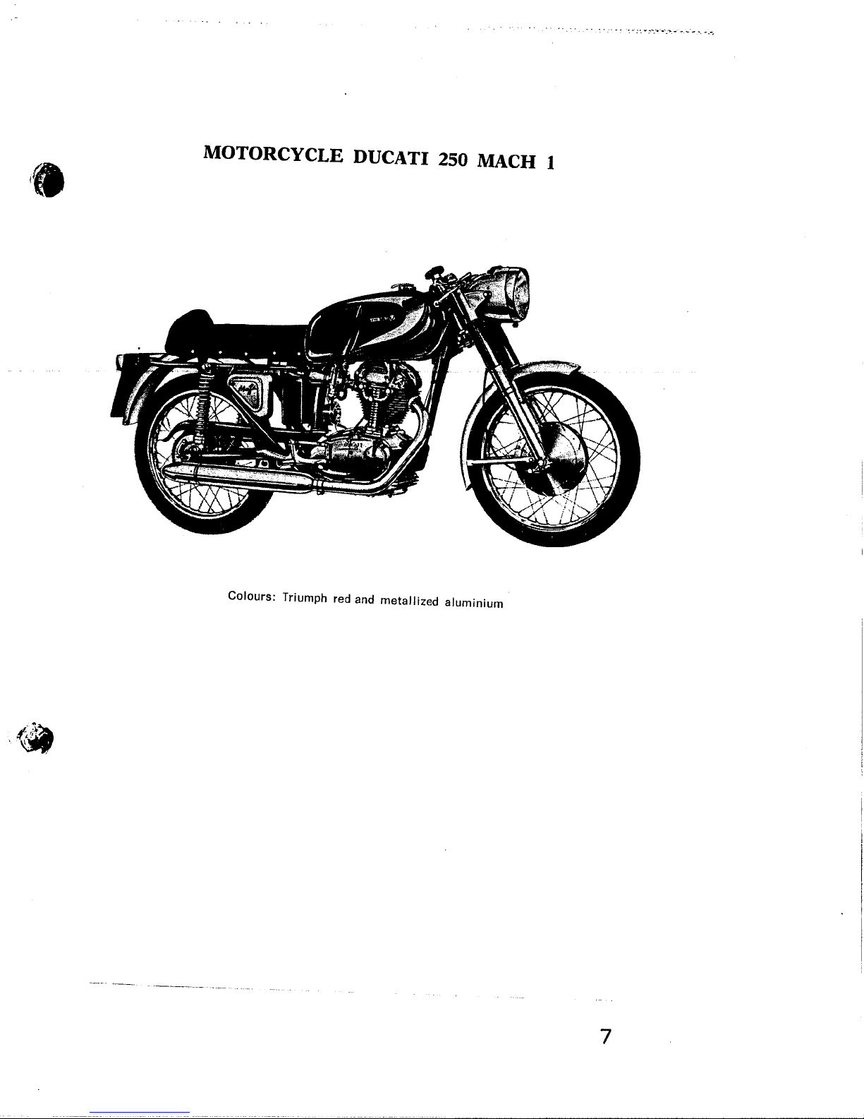
wn!u!wnie paz!iielaw pue paJ 4dwn!Jl :sJnofO~
---_..._---.._-_. '_. -----
L
III )UIVW osi iiV~na 3'13A3HOiOW
I.
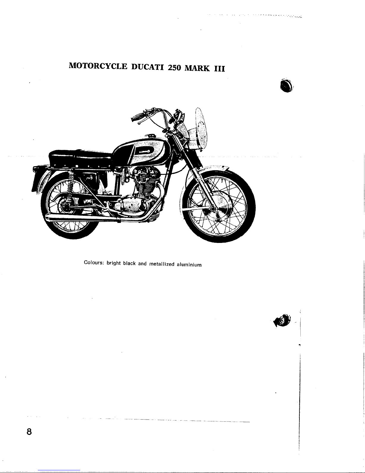
WnlU!wnle paz!lielaw pue )j::eiq l451Jq :sJnolo:)
'*
~
----------_..._--.._-----_._--- ---------- '-.- -- --_. .._-...._---- -- --~--_.~._- --.
e
.
_' _. ~_'~.'. -~ .~_-_ ~~~:"'-;-':~"":'~~""~;;'';'ø..~;:....~;:..;.-';::':-~.'
"7.-'''~-~-.''~-';~:''_-'~'.'7.~--~'--:;~.---.-: ~---:-':r::-:-:~:- ;~7 ... ~ ":.-: ~.- ~':':".:.:- .....:._..~:-..._.. _.... "', "_.'"
ll3:'1gWVll~S osi IL V3ILO 3:'13X3l10LOW
i;il1T
" ,., J;' -
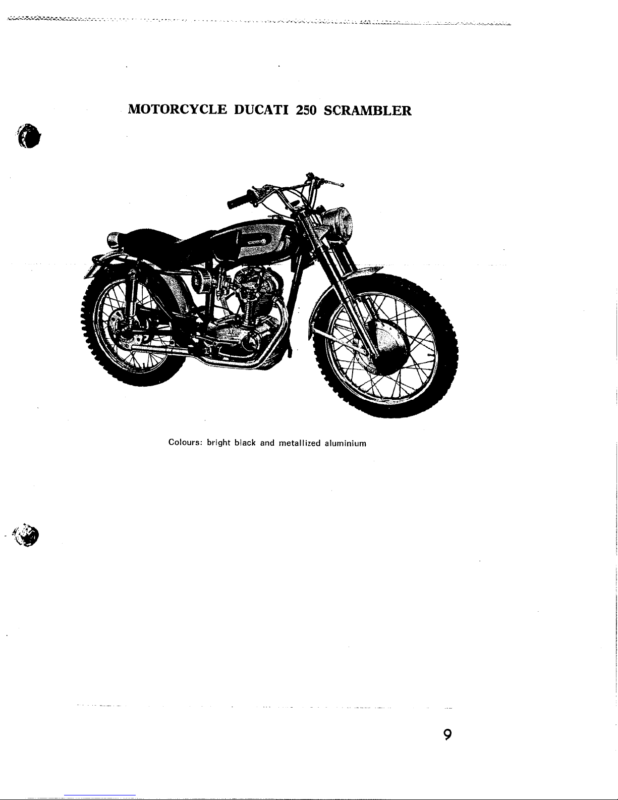
wniu!wnie paz!lielaw pue lI:ielq l46l.q :smol0:J
e~'
6

..'~ . ..'~.-:- :'':_~:'.'':=-~-'~. - .-- ...-...
A FOREWORD
The main goal of the present instruction booklet is to enable the
owner of an over head earn-shaft DUCATI Motorcycle to use his
vehicle in the best possible way.
The lollöwìng notices are tñerêtore only simple recommendations,
suggestions, advices, and terms of reference, sufficient to enable
anyone, having no experience or ignoring any special technical
knowledge, to use his vechicle and to maintain it for a long time
in perfect working condition.
i
(I
-l
10
.
.:.......:~:-..~~.¿...::Y.-~~-;.:;...-.. -... .', . ,'.. .. , ..'...~ ..-., ..:............. .......;.. _'L...~-_.. -~~_: _...~~.:....~.._..~..,;.~ -"--A',:.O ~'~"";'."._~'_'-"_ _:....~. ~. .. _ _:. _" ,_ .~.:.7"):.,:.. ~ ..' .. ..'''''' ,... ..~.. _:. :...~...:.~:: :':'''''~''::''.'..____''.....-_'..
'.
DUCATI SERVICING GARAGE
It is advisable when taking the machine to a garage for
repairs to ensure that the garage is a Ducati agent as the
staff will have been specially trained and the garage will
have been equipped with the necessary tools to carry out
any repair required. They will also carry a full stock of
genuine Ducati spares.
SPARE PARTS
It is absolutely necessary that each order for spare parts
clearly states the following data:
1) The catalogue code of the spare part (obtained from
the Spare Parts Catalogue of the model wanted).
2) Serial number of the engine (when ordering spare
parts of the engine).
3) Serial number of the frame (when ordering spare
parts of the frame).
~-t;"" .
l,
~"-
11
- ~ ~ ~ ~ 4 '_'~ :.'~ ~ "_'_~:_'#;.'~."
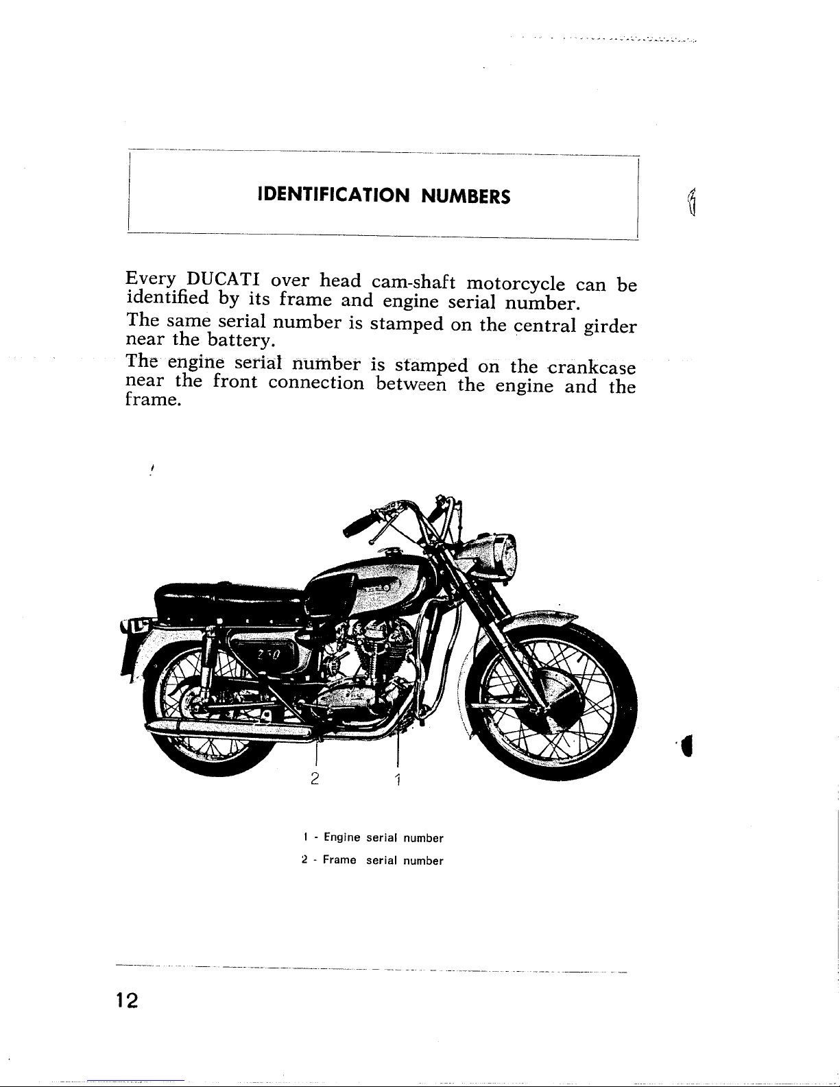
IDENTIFICATION NUMBERS
Every DUCATI over head earn-shaft motorcycle can be
identified by its frame and engine serial number.
The same serial number is stamped on the central girder
near the battery.
The engine serial I1ürtbet is stamped on the crankcase
near the front connection between the engine and the
frame.
/!
(0
-- -. ---_.-------_._----- -'--- - ._-- --
12
.t
I - Engine serial number
2 - Frame serial number
._- ------_._-. - - _... -- . -- -----_.-
~.~.~ -"'.":.'::'_.. .., ,=..-=~::.,:_';~::;.. ;.'_; ':.' ':' :....:,__.
.'".. .,'-". ..... '...~..'''' .... '.' ~.~ ,,~-.._., '-~ .~- '~'~-' -., ..... '~-,'~'.'4"':;"-~-":"""':';-'..": ..... ..-_.........." ..,. _"'_'~":':''~ _' ~ .'.
.
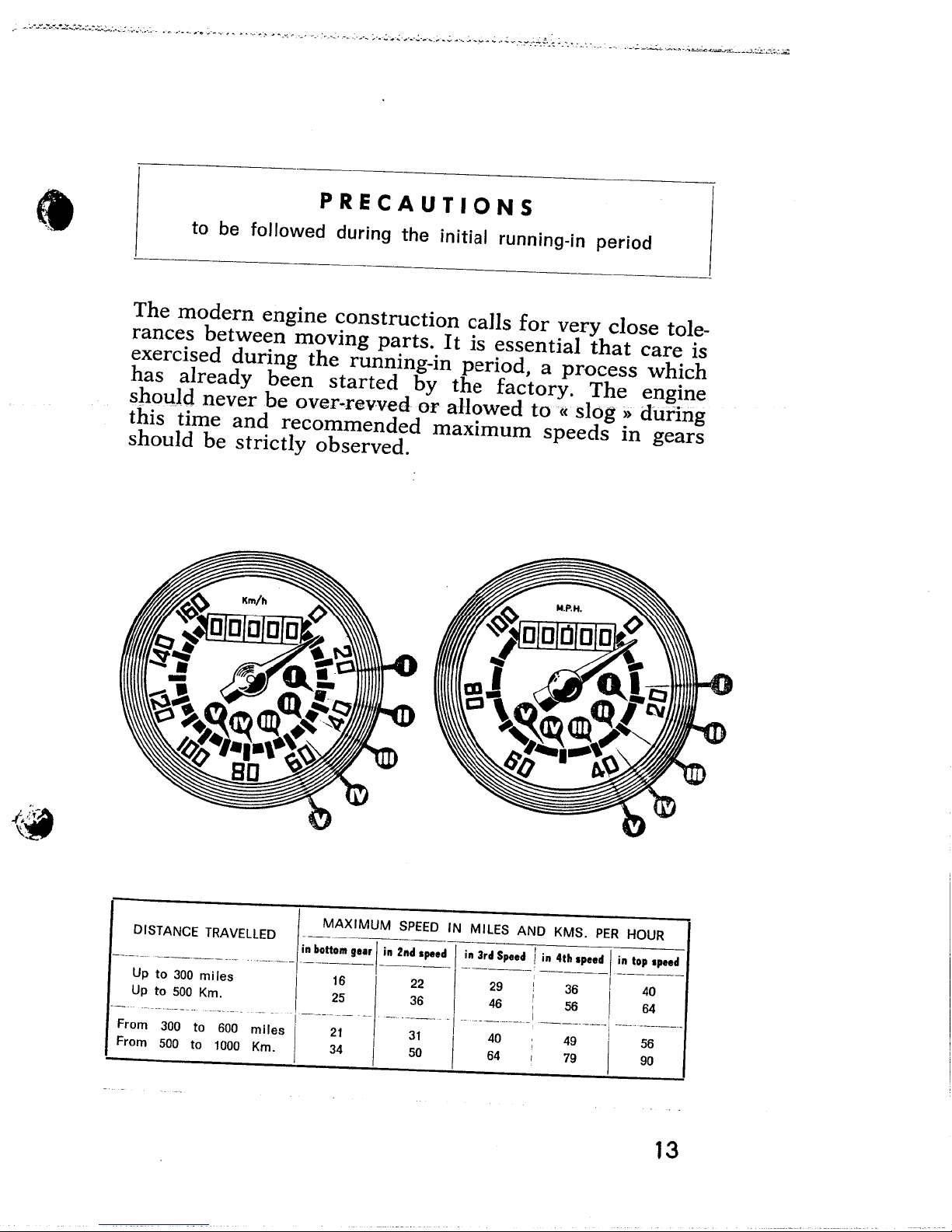
The modern engine construction calls for very close tole-
rances between moving parts. It is essential that care is
exercised during the running-in period, a process which
has already been started by the factory. The engine
sliolJJd never he over-revved or allowed to(( slög )) dtifing
this time and recommended maximum speeds in gears
should be strictly observed.
. " . .. _. .. ~ -. '.'
"-,:,,-~....~~, .~~~--~-""...:;:..:i,,:',.:
PRECAUTIONS
to be followed during the initial running-in period
t.
DISTANCE TRAVELLED
--~------ '_.__.~- ~,-- . .. -------
Up to 300 mi les
Up to 500 Km,
"-", '-""'-""-" '" -'-", ,..,..
From
300
to
600
From
500 to 1000
miles
Km.
¡, ..;.. ,.w I ;. -z;¡ .... ;. .'dO... i ;, .., .,"'! ;, h, _
. ---- _.._---'--- -----
----..,,-, ---" '-'--,-.. - ,..-,--,----! '--'-'---i --, -----,-
MAXIMUM SPEED IN MILES AND KMS, PER HOUR
16 22 29 j 36 I 40
~ æ ~! æ M
21
34
31
50
40
64
I
i
49
79
i
56
90
I
13
-'-". -- -_. -_...
-. - .'~.. ......;......-.. ....ø.....wo;"'..:'. ..~..'
. . - -., -'.
It is advisable to change the oil first at 300 miles and
then at 600 miles (with the engine warm). Re-adjust
the tappets, regulating the adjusting screw in the 250 _
GT and MONZA, fitting the rocker appropriate shim
in the other 3 models; tighten cylinder head and holding
nuts, crankcase nuts and screws. Do not overtighten
as damage may result in thread stripping or bolts brea-
king. Readjust contact breaker.
In order to ensure careful running-in the carburetor has
been fitted with a distance piece which restricts the full
use of the accelerator. After
moved by your Ducati dealer.
Failure to comply with the above recommendations
absolves the manufacturer from all
and any damage that may result.
600 miles this should be re;.
liability of guarantee
14
._~..- --_. --~_._- ---
l
--... ...- -~ ....__.._~_._--
~~"'X""'''':''::~~''''''.;;'..:__-__ _ _.. ~ _
,. C'_" ,. . '~::'. . .-,~. _,',. ..... .,..... '.' ..... ......_.. .,_'-_.~_-:..,,'~ _ _:. .~._
-. ..' .'. .. ~__ ~ _ ..a._ .'~
.
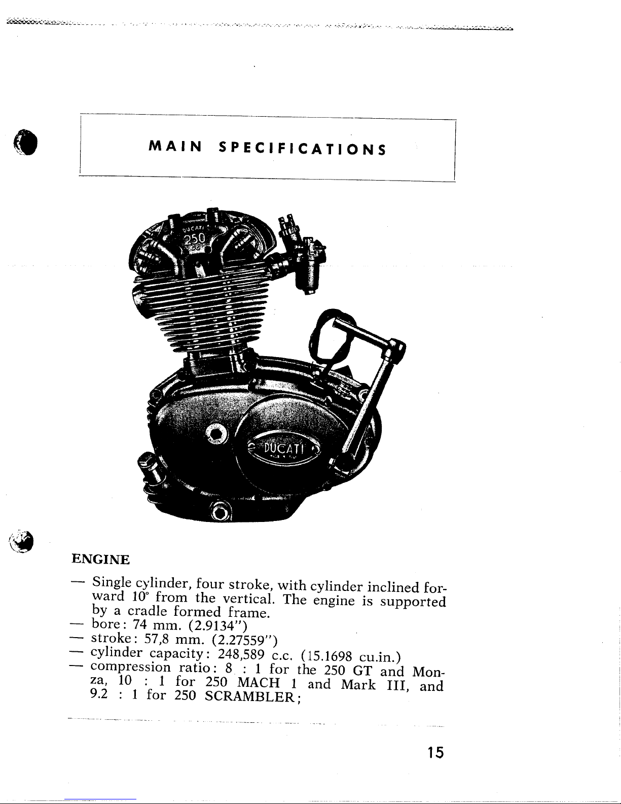
MAIN SPECIFICATIONS
',/~!(ir
ENGINE
- Single cylinderl four strokel with cylinder inclined for-
ward 10° from the verticaL. The engine is supported
by a cradle formed frame.
- bore: 74 mm. (2.9134l')
- stroke: 57,8 mm. (2.27559")
- cylinder capacity: 248l589 C.c. (15.1698 cu.in.)
- compression ratio: 8 : 1 for the 250 GT and Mon-
zal 10 : 1 for 250 MACH 1 and Mark III, and
9.2 : 1 for 250 SCRAMBLER;
15
- . , ~ , ~. -.' ~. ''; -','-:' .J..,. ~ '.........;._:'..":.~~..~~~:.;.....~......:./..:.;~-i"!.i..":
- combustion chamber with hemispherical ceiling;
- cylinder barrel of light alloy, deeply finned and with
inserted special cast-iron liner;
- connecting rod of special steel with big-end assembled
on a cage roller' bearing and little-end bushed to take
the gudgeon pin;
- pistons of light alloy, convex topped and in one piece,
with four piston rings, two of which are slotted oils
scrapers;
- cylinder head cast in light alloy and closely finned
with inserted valve seats.
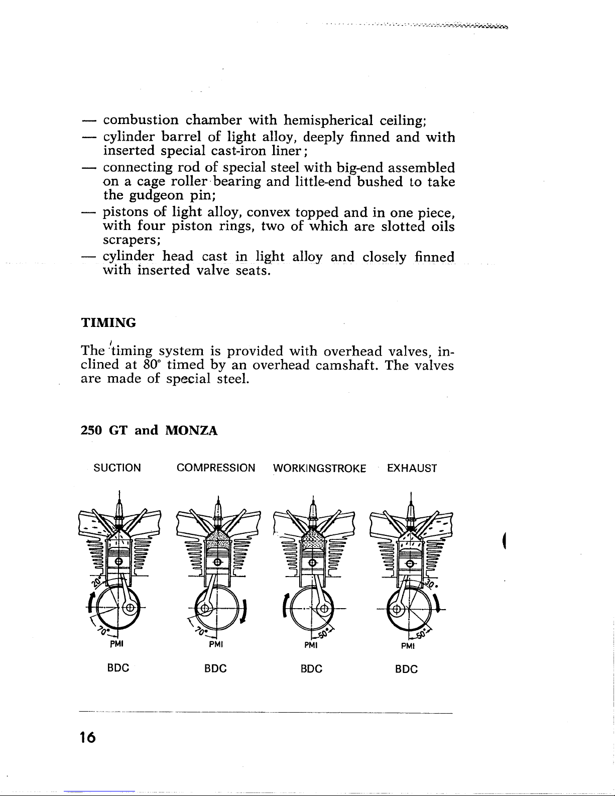
TIMING
The .¡timing system is provided with overhead valves, in-
clined at 80° timed by an overhead camshaft. The valves
are made of special steel.
250 GT and MONZA
SUCTION
COMPRESSION WORKINGSTROKE EXHAUST
~
PMI
BOC
BOC
16
PMI
PMI
BOC
PMI
BOC
~:Y:'~'-'';"'' , . -
.
~ r R.. ..". _.,_~ .. '...,;..~..........~_:.4'u.:~.....:"'~...:..:...~~.~~..~.....~~~.;..~~..,;.,:;.~~..:..-.j..,~..--.."._:-...._~~~_;.......,. "'_"-'-,:- "".."',~:"::-":~...~'-.-;.._#'
.. R. "'r .-'~''''",.:z"":~,,:-=..:;'._::~_._.,_..,
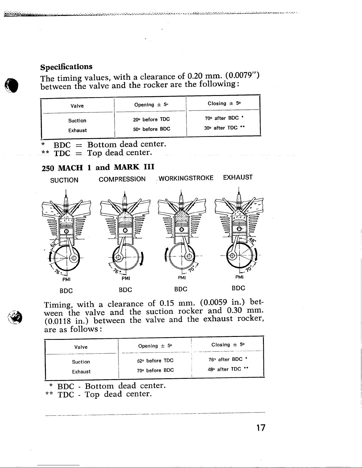
Specifications
The timing values, with a clearance of 0.20 mm. (0.0079")
between the valve and the rocker are the following:
Opening :t 5"
200 before TOC
500 before BOC
*
BDC
** TDC
Valve
Suction
Exhaust
i
Bottom dead center.
Top dead center.
250 MACH i and MARK III
SUCTION
COMPRESSION ,WORKINGSTROKE EXHAUST
I
I
Closing :t 50
700 after BOC .
300 after TOC ..
/:!~
\~~
PMI
BOC
BOC
BOC
BOC
Timing, with a clearance of 0.15 mm. (0.0059 in.) bet-
ween the valve and the suction rocker and 0.30 mm.
(0.0118 in.) between the valve and the exhaust rocker,
are as follows:
--_.._..~- ~--------' ---_.._-'---
Valve i Opening :! 5°
Suction 62° before TOC
Exhaust 700 before BOC
Closing :t 5°
76° after BOC .
48° after TOC ..
* BDC - Bottom dead center.
** TDC - Top dead center.
---,._~----- - -----.~_._----- _.,--------~
17
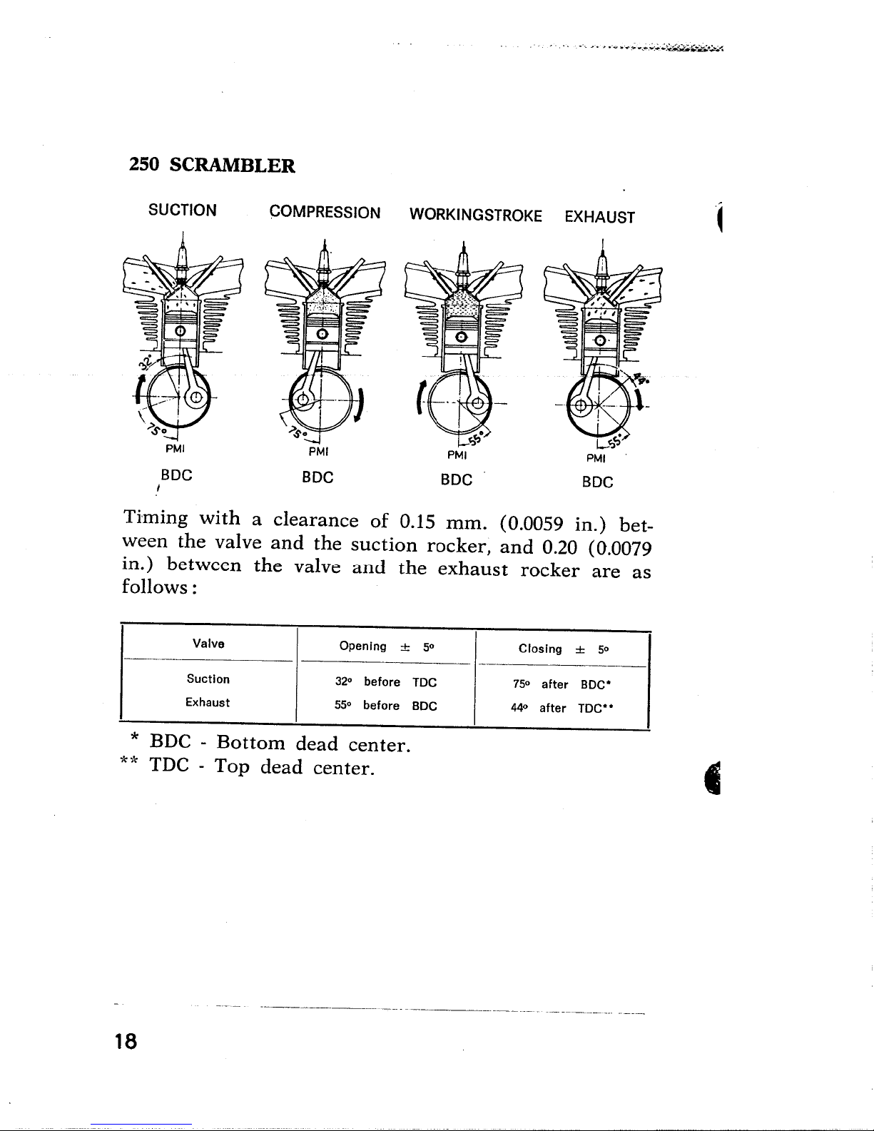
250 SCRABLER
'''/0. ..-.."...."'...;..;....:.:..:.;~~;;~..~.-
SUCTION
BOC
i
COMPRESSION WORKINGSTROKE EXHAUST
PMI
BOC
BOC
BOC
Timing with a clearance of 0.15 mm. (0.0059 in.) bet-
ween the valve and the suction rocker, and 0.20 (0.0079
in.) between the valve and the exhaust rocker are as
follows:
'~
-,
Valve
Suction
Exhaust
Opening
32°
before
55°
before
* BDC - Bottom dead center.
* ,.. TDC - Top dead center.
~'--'-'- -~------- ----
18
:f
5°
TOC
BOC
Closing
75°
44°
after
after
:f
BOC'
TOC"
50
~
'':..~~~~.i''~~~.:.:~.:~- ...... ~.. . . ~. ... 'w' A';' '... ',_-~,'~~~.'~_.::,~.:...~~..'",,,'':~'';~;'J':';:'T:''::'-:''.;-:-'::''''''::....~ ..-. ".:':-i, ...... -.:~~~e.~,:..:.-......:.:_
" - ."". -... .",-' ~"...-:.-..,-;,--,~.;...-~~.;...::~~::~
.
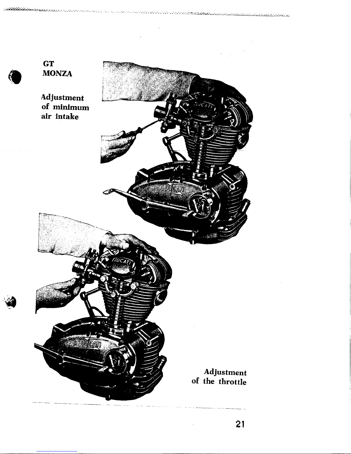
GT
MONZA
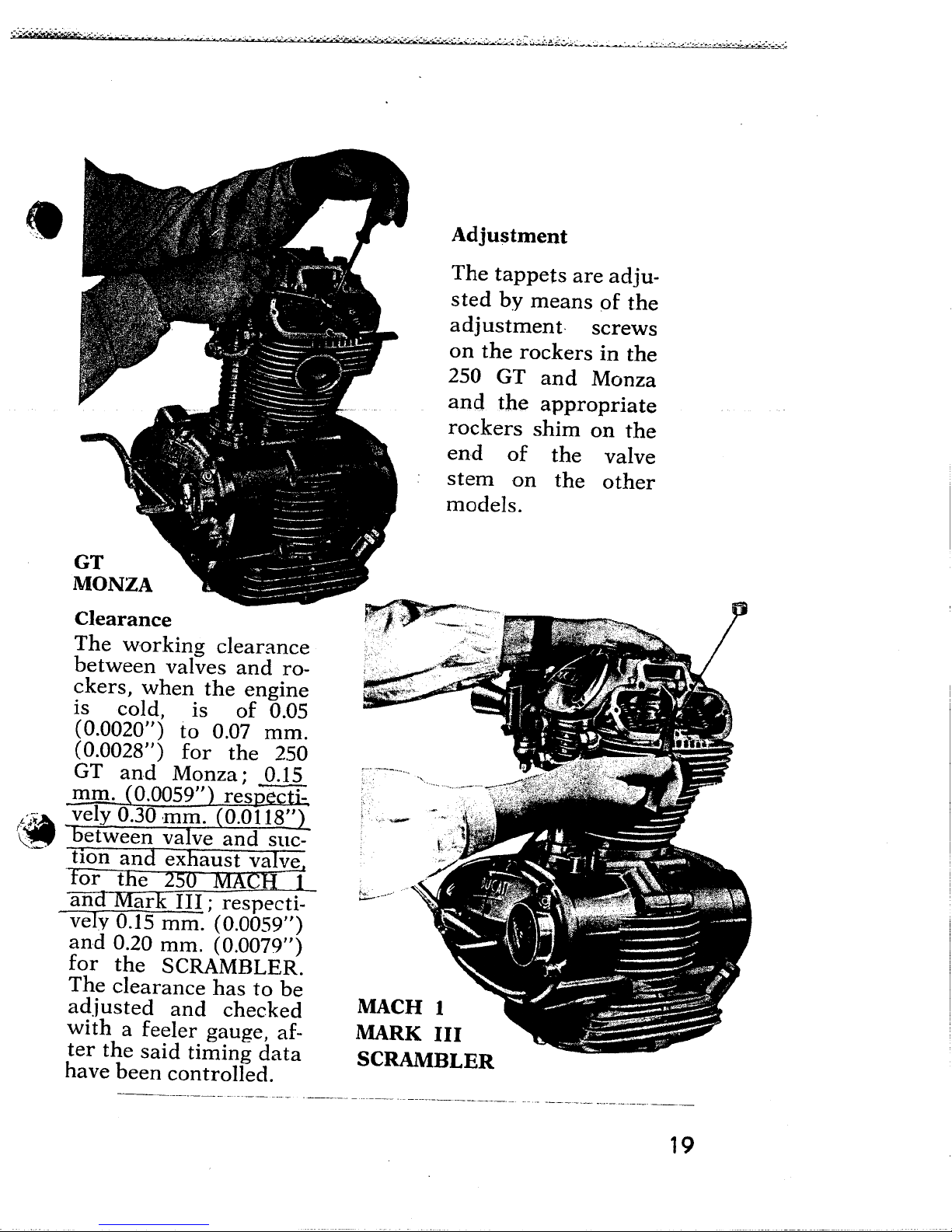
Clearance
The working clearance
between valves and ro-
ckers, when the engine
is cold, is of 0.05
(0.0020") to 0.07 mm.
(0.0028") for the 250
GT and Monza; 0.15
mm. (0.0059") respe
Li~ . vely 0.30 ,mm. (0.0118"2
t"' -Detween valve and suc-
-- tion and exhaust valve.
'for ~e 250 MACH -i
and ark III; respecti-
vely 0.15 mm. (0.0059")
and 0.20 mm. (0.0079")
for the SCRAMBLER.
The clearance has to be
adjusted and checked
with a feeler gauge, af-
ter the said timing data
have been controlled.
--~._---~_._------_._- .-__.- - ---._.- _.. ---_..- ._- ---------~._._--- ..- ..- ---_.._---- .".--'-- ---'----
Adjustment
The tappets are adju-
sted by means of the
adjustment screws
on the rockers in the
250 GT and Monza
and the appropriate
rockers shim on the
end of the valve
stem on the other
models.
MACH 1
MARK III
SCRAMBLER
19
.... ~ ---.. '_ .'_' _-;. "~':,'.':~_.o-.'~': w.=".O:....:"..O:...4-_...........~:-..
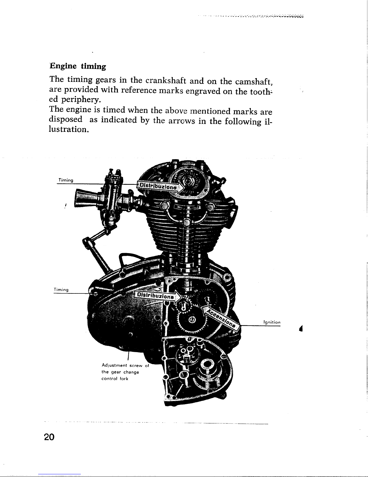
Engine timing
The timing gears in the crankshaft and on the camshaft,
are provided with reference marks engraved on the tooth:.
ed periphery.
The engine is timed when the above mentioned
marks are
disposed as indicated by the arrows in the following il-
lustration.
Timing
. - ,'-, +,~ ~ . ~ - ~
20
Timing
Ignition
.
AdJustment screw 01
the gear change
control fork
.
.,.,":...,."O"~.~'O-,.-:.n~-;-,--c~,-"~~."""o',~'~;"~,-mo,----;-;:: '" ,.,.:~ -:- ,.., ',':' ,'" ,",',,", .. ,.. C', ", , , .., ',-,' " " . _ _ , ',' ',' ". c ._.' ,'. _ '.. .'" ._. -.-..-.c _", _-i _""~""~.:~.~.~.~ ~ '
i~
VZNOW
lu3U1lsnfpv
uinUlJUlUI )0
3:aelul .lie
~1!;~1
~,'
- _. ...._..- .__. -~----~.- -----.__._----~- ----------._-
lu3U1lsnfpv
3lno.lQl 3Ql JO
_. _.._-~- '-'-- --~------
iZ
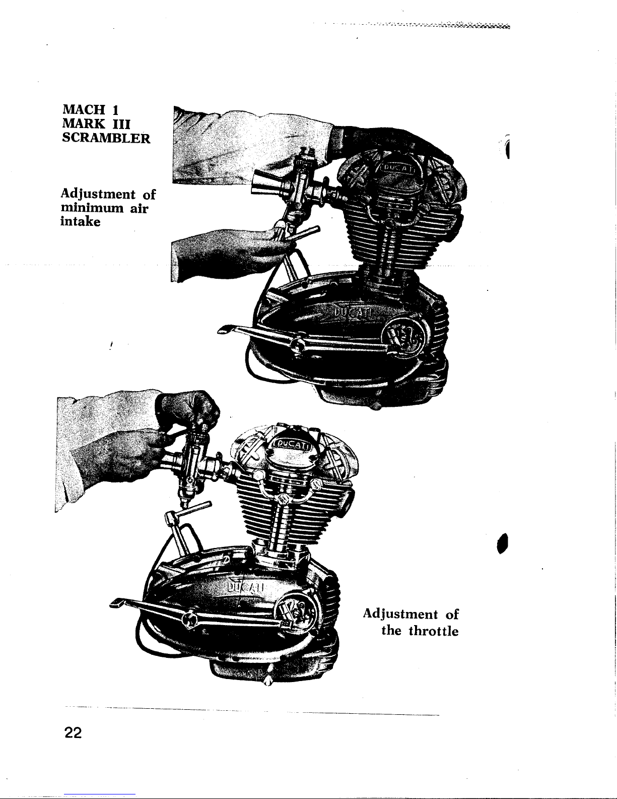
I H~VW
ai¡elu!
III )llIVW
lI3:'1HW\~S
)0 lU3wisnfpv
.lie wnwiuiw
~~-;~~-:.J~",-::,.,~f"'~~".,~-:.~~.~:."'''''''''''';:'._~-~.__R..-_-,-,- '.' - -.. ~ -
L
GG
,
)0 luawlsnfpv
a(Ho.lql aql
_..~---_._-- --------.__...._-~-_..
,
"".
.
.,,
"
,
.:
I.:
I::
t;
"
r,
¡\'~
f
I
t:
.
"
t:
~:
~:
",
;
"
r
r
i
.'
(
,
II
"
(
t
c'
\
~. :
(
I.
~'
I-
~,
(c
¥.'
~ '
I'
L
~
f
t
~
.
t
:~
t'
ia'
330
272 071 /
016
'¿ 132
"""-136
I\
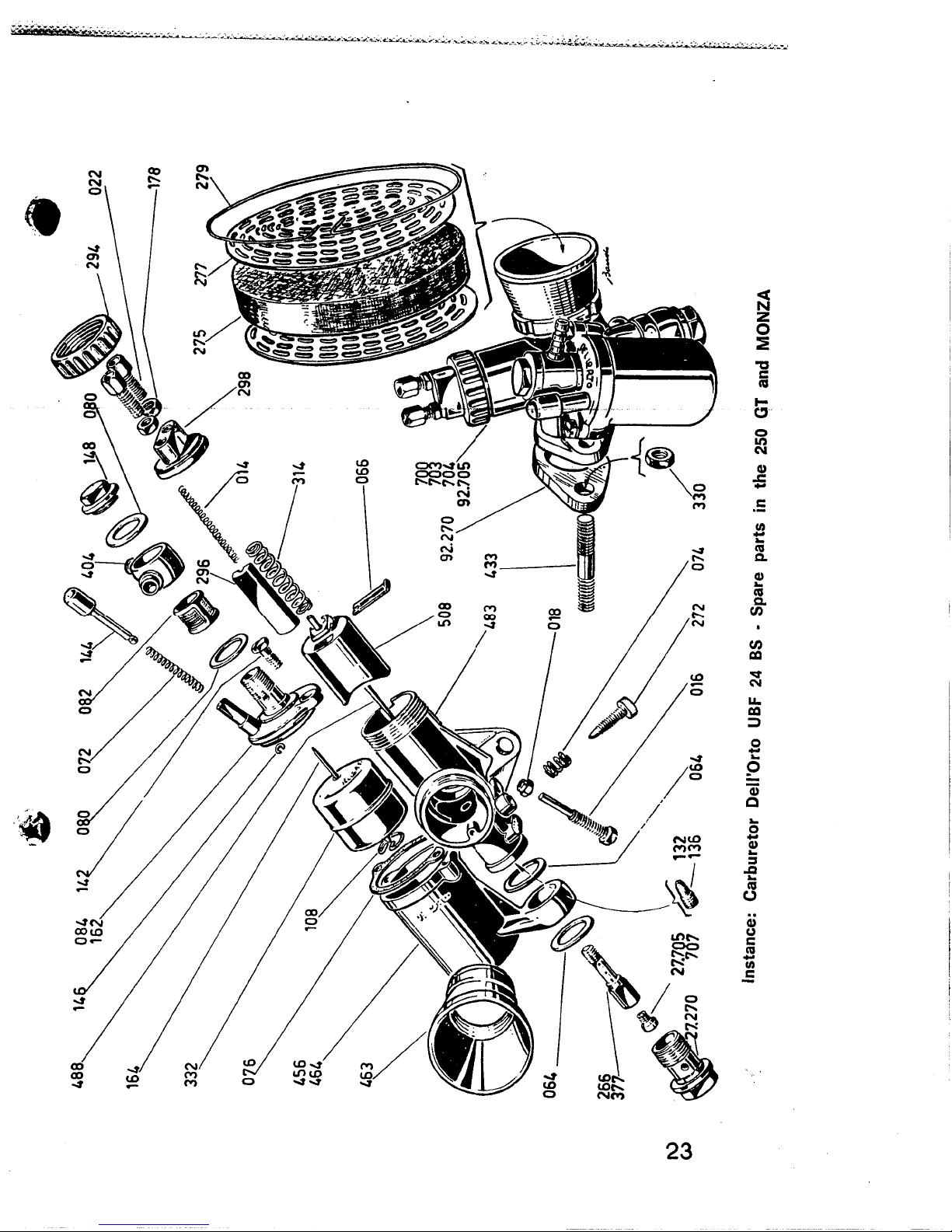
Instance: Carburetor DellOrto UBF 24 BS . Spare parts in the 250 GT and MONZA
úJ
. .." ~."'.. -' _ r _~.."..;:".."":::;~.':--",:"'_..~:.".:,,~'~~:"!- . - ~ ~ ; -~ - - . ~. ~ ~. .
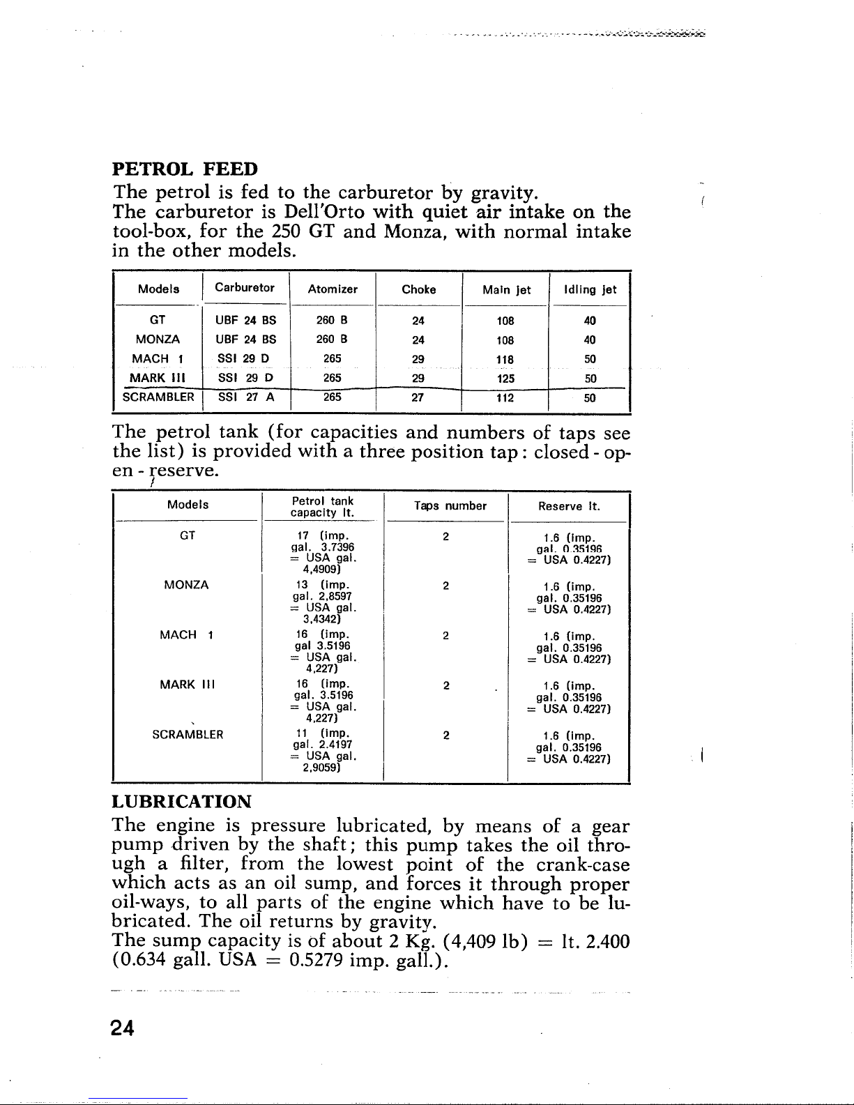
PETROL FEED
The petrol is fed to the carburetor by gravity.
The carburetor is DellOrto with quiet air intake on the
tool-box, for the 250 GT and Monza, with normal intake
in the other models.
.- -. ' ~ ,- , - "
Models
GT UBF 24 BS 260 B
MONZA UBF 24 BS
MACH 1
MARK III
SCRAMBLER I
I Carburetor
SSI 29 0 265
SSI 29 0 265
SSI 27 A
Atomizer
260 B
265
Choke
24 108
24
29
29
27
','
Main Jet
108
118
125
112
Idling jet
40
40
50
50
50
The petrol tank (for capacities and numbers of taps see
the list) is provided with a three position tap: closed - op-
en - reserve.
l
Models
GT
MONZA
MACH 1
MARK III
,
SCRAMBLER
Petrol tank
capacity It,
17
(imp.
gal. 3.7396
= USA gal.
4,4909 )
13
(Imp,
gal. 2.8597
= USA gal.
3.4342)
16
(imp, 2
gal 3,5196
= USA gal.
4.227)
16
(Imp,
gal. 3,5196
= USA gal.
4.227)
11
(imp.
gal. 2,4197
= USA gaL.
2.9059)
Taps number
2
2
2
2
Reserve It,
1,6 (Imp,
gal. 0,35196
= USA 0,4227)
1,6 (imp.
gal. 0.35196
= USA 0.4227)
1,6 (imp,
gaL. 0,35196
= USA 0,4227)
1,6 (Imp.
gal. 0,35196
= USA 0,4227)
I
1,6 (imp.
gaL. 0.35196
= USA 0.4227)
I
LUBRICATION
The engine is pressure lubricated, by means of a gear
pump driven by the shaft; this pump takes the oil thro-
ugh a filter, from the lowest point of the crank-case
which acts as an oil sump, and forces it through proper
oil-ways, to all parts of the engine which have to be lu-
bricated. The oil returns by gravity.
The sump capacity is of about 2 Kg. (4,409 Ib) = it. 2.400
(0.634 galL. USA = 0.5279 imp. gall.).
24

.'
.. --- ......."'~":.,~~~~.;...:...a~~.:~~..1
~_~-,-~..-7'.... p' ..-
~;.-~--.-,_.-..._--
..
. : - -- ~
~~
e'í
P
~
E ;
~ f¡
e
SG

An Oil-filler with stick consisting of:
1) Stick-provided filler plug;
2 ) Sealing gasket;
3) Filler;
4) Sealing gasket;
". .'_"__ ¡'. .._.:,.:~:;-:..~...;...::.:.~.::;~~~~;..:~gi;"'.;~;t
i d
allows the oil
level
measurement.
The filler plug stick is marked by two notches in the spots
where the oil level is respectively at its lowest and at its
highest point.
The oil level is measured by just resting the plug on the
filler.
_ The lubricating system of the DUCATI motorcycles
with single over head earn-shaft engine is of the sim-
plest and requires no special maintenance except the
renewal of the oil level ( 8 ESSO EXTRA MOTOR
OIL 20 W - 30-40 or RACER 40) each 500 Km. (about
310 miles) and the total change of the oil, including
the cleaning of the filter every about 2000 Km. (about
1240 miles).
26

;:it~:;':';~"'':''-''.:...... .~~ -'-_;"':-'_'__:_.:::_--=.~. ~_~ o. __~~;_~ ~ ~ _ ok _ __ ~
CENTRIFUGAL OIL FILTER INSERTED IN THE MAIN-
SHAFT
.
,:Æ.&.
~
D
~
How it works
The oil which is to be filtered, is brought to the filter
through the pipe A; from here, the centrifugal force eli-
minates all the impurities (which are heavier than the
oil), which accumulate all around the threaded plug B of
the main shaft.
The filtered oil, goes through the tube C to lubricate the
big end, and through the duct D, to lubricate the engine-
clutch housing gear.
COOLING
Cooling of the engine is achieved by close finning of both
the cylinder and cylinder head.
27

. - ,.' - _ _ __C'_ _'~'_'_'~-_',C-_~"',"".'''~';';;:ç..;g-,~
IGNITION
The ignition is battery-coiL.
The partial automatic advance ignition is:
Model
GT
MONZA 5° to 8°
MACH 1
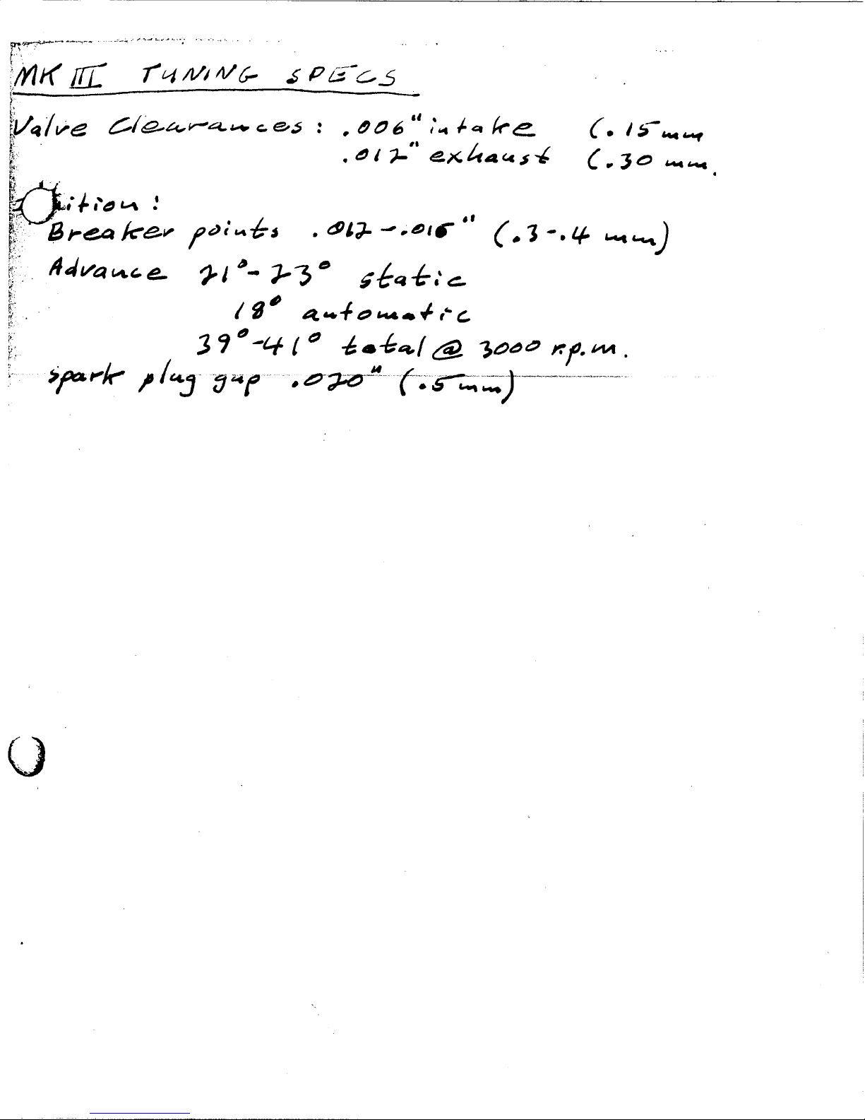
MARK III 21° to 230
SCRAMBLER
Advance with
stopped
I
i
I
5° to 8°
5° to 8°
21° to 23°
engine
Amplitude of
outomatic advance
28° 330 to 36°
28° 33° to 36°
200
18° 3)0 to 41°
180 390 to 41°
Total advance with
engine running at
3,000 r.p.m.
330 to 36°
For setting up the ignition, see figure on page 20.
The clearance between the platinum plated contacts is of
0.3 to 0.4 mm. (0.0118" to 0.0157") and has to be checked
bY means ot the feeler gauge (see figure hereupon).
The ignition plug is a Marelli CW 260 N, or a similar
model and is located on the leftside of the top of the
cylinder head.
When replacing the sparking plug make sure the angle of
the plug, relative to the plughole, is correct otherwise the-
re is a risk of stripping the thread in the cylinder head.
Screw the plug lightly at first, then tighten it.
28

ej
- ~:~~_":-~-=:-;:...:;....,.....;:.~;c-__.~.:..::-~.#. ....'---'~-.. .~~..' ....,. ..... ,-.... ...".... -','. .......... .~.... ..~..:--..~~..-~.-'_...-,..O-:----.-,.:'-..:'-7..:'~-.-~'-~'~o:-c..:-.::-~":...;::-.. ....':""~~~~~
'a:J1Jzd lo ¡no JOU f\')
. Cr .grd) JdAOJ din
-. -----_.. -. "-- _.__....._------------
3:;)NVACIV )llIVdS NOI.LIN~I )I;)3H;) O.L MOH
dqi Jdlju) d;)UUAPU )(Juds uorlrugr dq1 ÁnU;)rpOpdd )(;)dqJ
dql iuqi dJnS dq ~ (sdHll OOLI ÁJdAd 'JdijU 'puu 009 lSJg
-U;)pqni IIdM Sr H iuql 'ÁpddOJd S)(JOM d;)rAdP ;)nUll01nu
ad1Jis lo Jno JdqHdU dJU sgupds dqi 1uqi pUU Pdl " ,;tf'
dq isnrn d;)UUAPU JnUllolnu dql jO dpnindllU ÁJUlOJ dq1
-uoW 'in SPPOll dql ur ijuqs gUrAPP dql uo 08L Ol iunbd otr
gUrAPP dq1 uo 081 01 iunbd 06 dq lsnll puu 'i q;)UW 'uz
nOÁ jI 'lI3:'lHWVlIJS puu III )(JUW SIdPOll dql ur ljuqs
'dOqS)(JOM pdZnUpdds U Áq Pd)(;)~q;) H idg 'iqnop ÁUu dAUq
: SJ\\OIIOj SU Pdd;)OJd 'd;)UUAPU )(Juds dql )(;)dq;) 0i
gUrAPP dq1 iu Sr q;)rqM gnid pdpUdJq1 dqi dAOlldlI - 'lsT.
'(r ,grd) lJuq;: gUrlln diquHns B 19 pUU 'IdAdI ijuqs
dJnJdS iuqi MdJJS dqi jO dUO uo JOiU;)rpur UU a~ - 'PUL
ci

", .... ~'~'-_-_-~"_~:~~~:-__"-~--.~""~"'''''_'"-~''''~Â':~;':~~~~
3.rd. - Bring engine to TDC of compression stage and set
the indicator at (( 0 )) of the timing chart.
4th. _ Rotate the driving shaft clockwise for about a quar-
ter of a turri.
clockwise
5th. - To the spring' of the mobile part of the contact
breaker connect a 6V. - 3W. lamp in series with the
+ of the battery (Fig. 2). The lamp should light up.
30
anticlockwisp.
(Fig. 1)
- .- - -- . --~-- _.- -_.---_. ----------.---
------------_.
--_.----- - ~--

f~..~f"".'''"-I0~-:-.._":,... . ".~ .";-:.:.. -'...""./~ ..--:":.__.:. ~ -. .
6th. - Rotate the driving shaft slowly, anticlockwise, till
A
~
the light goes out or its intensity is lowered.
At that very 'moment, the indicator should give on
the goniometer the advance degrees you will find
on page 28.
a
To + of battery
(Q
(Fig. 2)
31

'.:' '-'..,',...'-.,.,-"----'.',"'i_..;;~""*~~.;
\
I
(Fig. 3)
7th. - To be on the safe side, it is advisable to repeat the
test.
8th. - If the reading should not tally with the requested
numbers, then loosen the two screws (A and B)
which secure the plate, and rotate it, advancing or
delaying ignition until the right number found at
page 28 is obtained.
9th. - Bear in mind that if you let go dry the felt which
lubricates the earn, the fibrous slipping block (that
operates the opening of the moving part of the con-
tact breaker arm), will tend to wear out, lowering
thus, the value of the gap.
------.- --_. ---~ --~-- ~------------ -----------
32

~~~~;'~~~;".i~"!;,"~~":i:':..~..J.~:":;~~':;'''''~'.'''::'.''~~'.~'''''''''"'_.._/-.', '_,'", _'
STARTING
._.__-.._.:_:"-':.;",_,,~'. : '" ~-,;'. ;
.
The kick-starter is located on
the left hand side of the en-
gine. In the case the starter
unit is refit, it is indispensable
to carry it out as shown in the
figure aside.
TRASMISSION
The transmission components comprise a clutch and a
gear box. The clutch is òf the multiple plate type with
\~
-----~---._--_....-
_.._--_.. .....- -~---------_._-~-- --_._-- _.._.. -'---------
33

,'. - . - . ..-.. ..-~-~ "'-A"~'_~'~''''':'':'''''~:;;;''_~:~~';*~''JI''~''''Y:'lî
steel and phenol resin disks. It turns in an oil bath and
is mounted on the primary shaft on the gear box.
The clutch housing, made of special wear resisting cast
iron turns on two inner bearings which are set at an ade-
quate distance. It is lubricated together with the engine
sprocket as already explained in the paragraph of the
centrifugal filter. ,
This system ensures smooth movement, solidity and long
wearing; it has been fitted and tested on the 200 cc.
motorcycles, since 1960.
The clutch is operated by a handlever placed on the left
hand side of the handlebar.
the transmission between the engine and the primary
shaft of the gearbox is obtained by means of gears and
the reduction ratio is:
2.500 to 1.
The gearbox is mounted in the crankcase; the gears for
thq 5 speed gearbox are constantly meshed and are ope-
ra fed by a foot pedaL.
The transmission ratios of the gears are the following:
- in bottom gear 1 to 2.53
- in second gear 1 to 1.73
- in third gear 1 to 1.35
- in fourth gear 1 to 1.10
- in top gear 1 to 0.97
The transmission between the gearbox and the rear wheel
is made by means of a chain and the speed ratio is:
/..647 to 1 for the 250 GT and Monza.
2.222 to 1 for the 250 MACH 1 and Mark III,
3.929 to 1 for the 250 SCRAMBLER
FRAME
The frame of the DUCATI motorcycles is of a very smart
and modern design, is manufactured with high tensile
steel and is of the central girder type.
SUSPENSION
The front suspension is composed by the DUCA TI te-
lescopic - hydraulic long-stroke fork, with steering rod.
Each fork leg contains 1 -; 110 cu. cm. (cu. inch 6.1025
to 6.7127) of HYDRAULIC FLUID 542 oiL.
-" --."-- .._--------------------_.-
34
----~---_._-

~"'k'¡I.~"ef:~.';....-,~;;""..-:.;......:;.:..~::.:.~.._;.:'.._~.:.~~.~~_~...__...._..
The rear suspension consists of a robust hinged fork with
double action hydraulic dampers, (shock-absorbers) ,
...
which can be adjusted for three differentt loads: Mini-
mum - Medium - Maximum.
On these machines the fork fulcrum-spindle is fixed to
the frame while the fork with bronze bush rotates on it.
This gives the machines greater solidity and stability.
~:."=.IIÌ.'k.:H,~'~
\
\
~
WHEELS
The wheels are of the spoke type with rims as follows:
Model
250
Material
Wheel Rim
-~--- ._-----~.._-------
Profile
Wheel rim size
Front
Rear
GT
MONZA
MACH 1
MARK III
SCRAMBLER
Steel
Steel
Steel
Steel
Steel
Normal
Normal
Normal
Normal
Normal
18 x 2112
18 x 2112
18 x 21j4
18 x 21/4
19 x 21j2
...__.---- --- ._--------_.- ---.- --_._-------
18 x 2112
10 x 2112
18 x 2'/4
13 x 21/4
19 x 21j2
35

_ . _ ,. ~ ~.~ _._. _ ~.~ ....~.:.,...:..:..:..-Y':..:~;;~~..~~-;,;~~;.;.~;,:.R.:.,~::tt~v..;"..~
The front wheel has a detachable spindle.
The rear wheel has a special cushion drive.
Tyres and pressures are as follows:
Model
250
GT and MONZA
MARK ILL and
MACH 1
SCRAMBLER
"
2.75-18 ribbed
2.50-18 ribbed
"
3,00-19 grooved
for Motocross
Front wheel
Tyre
Pressure
2,25 Kg/cm2
(32.01
Ib/sq. inc.)
2,25 Kg/cm2
(32,01
Ib/sq. rìiê.)
2,25 Kg/cm2
(32,01 for Motocross
Ib/sq, inc.)
3,00-18 grooved
2,75-18 grooved
3.50-19 grooved
Rear wheel
Tyre
Pressure
2,25 Kg/cm2
(32,01
Ib/sq. inc.)
2,25 Kg/cm2
(32,01
Ib/sq. inc.)
2,25 Kg/cm2
(32,01
Ib/sq. inc.)
BRAKES
'Dhe brakes are of the expanding type with two brake-
shoes, - hand operated the front and pedal operated the
rear - with finned brake drums of large diameter width,
and with non fade brake linings.
The diameter of the front brake drum is 180 mm
(7.0866") , the diameter of the rear drum is 160 mm
(6.2992") .
NEW ELECTRICAL SYSTEM
(250 GT - MONZA - MACH i)
The lighting is provided by a storage battery which is re-
charged by the DUCATI flywheel alternator and rectifier.
The head-lamp APRILIA of large diameter carries 3
A mile speedometer VEGLIA with dial of 100 for the
250 GT and Monza, and of 150 for the 250 MACH 1,
lights.
is incorporated in the same headlamp.
The 3-way switch for the light control is situated on the
head lamp. A removable key, placed on the headlamp pro-
vides the contact for the ignition. By removing the key
the engine is stopped.
Alongside the lefthand grip of the handlebar is the switch
for the diplight, the antidazzle light, and the button for
the horn.
- -'--'---._-~ ---._._---- ~-"--~- -------_._~---.~-~
36

'~"'~';~.N;'''.~~"''.,...-.,-:''''''~''':''.;';''..''.!~:.':",'_.:..;_..,:.;'::"_~',.. _~ -.._..._,_...
In the normal position on the rear mudguard are placed
the number-plate carrier, the rear light, the reflector, the
¡,
numberplate lighting and the Stop-light. ,
When the engine is stopped, the electrical current for the
position lights (town light and rear light) is provided by
an acid cell storage battery SAFA, mod. 3L3, of 6 V - 13.5
Ah; the charge is maintained by means of the flywheel al-
ternator and rectifier.
To avoid ruining the effciency of the rectifier, never run
the engine without battery. -Í In cas~ the battery is dischar-
ged, see remedy on page 50.
. - .. -".." . ~. ",-' .," . - _..' ._~ : "~.._,;.;"",-;;:-~. -
-."-_"__~ 'A".~~_~~~ ~_..._._ _"_"___.
ADVANTAGES OF THE NEW ELECTRICAL
EQUIPMENT (250 GT - MONZA - MACH 1)
The electrical system with static regulator of current of-
fers real advantages in comparison with the system em-
ployed till now.
The advantages can be summarised as follows:
1) Regulation of the automatic charge.
2) There are no electrical contacts with the regulator and
therefore there is a grea,ter surety in the working.
3) Simplified commutator system which is limited to the
sole lights section.
~, 4) Possibility of controlling the charge through the red
pilot light.
S) Protection of the electrical system on 3 fuses and then,
possibility to briefly locate the eventual breakdown
and allow the remainding part of the equipment to be
operative: the fuse (7) protects the equipment of the
fr0nt and rear parking lights; the fuse (13) protects
the equipment of the head light (dazzling and anti.
dazzling); the fuse (14), the horn and the stop indica-
tor (see the electrical scheme).
6) Greater simplicity of operation and wiring.
-- - ----- ---- -~---- ~- -,- ~-'--"~--'-
37.

WIRING SYSTEM OPERATION
(250 GT - MONZA - MACH i)
'. ~ .......' ~..". Y," ...:-.::."'..~;,~.,:'.,.:.;~.:....~~~~
1) Key inserted:
the red ignition light lights up when the engine is star-
ted and revs at tick over. The light should go out and
stay out all the time the engine is running faster than
tickover.
commutator:
position 0 - light switched out
position i - switched on the rear and
front parking lights as well
as the green warning light.
position 2 - switched on projector light
l commutable in dazzling and
anti-dazzling lights.
the horn is operating
the battery
charge is well-
balanced in all
conditions.'
the stop indicator is operating
2) Key not-inserted:
4
the machine cannot be run
the red warning light does not lit
commutator:
position 0 - lights switched out
position i - switched on the rear and
front parking lights as well
as the green warning light.
the battery
cannot be
charged.
position 2 - projector light does not lit.
The connection between the static .regulator of current
and rectifier-battery is cut-out.
The horn does not operate.
The stop light indicator does no operate.
38
,~

7 - Fuse protecting the system of the front and
4 . Generator 6V.60W
5 . Plate carrier and Stop Light 6V-3/15W
6 - Stop light switch
2 - Ignition coli In cc, 6 V
3 . Sparking plug
1 . Contact breaker.condenser
the rear parking lights
KEY TO PARTS OF THE ELECTRICAL SCHEME
13 - Fuse protecting the projector light equipment
11 . Three pos iti on commutator
12 . Extractable 4 contact-key
10 - Bulb for the charge warning red light 6V-1.5W
9 - Bulb of the headlamp 6V-25/25W
8 . Bulb for front parking light 6V-3W - warning
(dazzling and anti-dazzling)
green light
!
~
I
ELECTRICAL SCHEME (~~50 GT - MONZA - MACH 1)
19 . Battery SAFA 313 . 13,5 Ah - 6V
lOA
--'---'~-,-.-.-:-,"" .,.... ....-..'
15 . Horn push buton
16 - Terminal block for headlamp
14 . Fuse protecting the horn and the Stop'
indicator
17 . Horn 6V cc,
18 . Static regulator of current and rectifier 6V _
14 13
10) (11
12
..
~
c:


ELECTRICAL SYSTEM (250 MARK III - Scrambler)
The engine of the DUCA TI 250, MARK III and Scrambler
is 'supplied with an alternator-flywheel magnet of the
outer H.T. coil type.
The coil supplies the lighting plant with 40 \V.
The components of this generator are:
1) the rotating flywheel, comprising "the magnets with
their polar expansion, the drum~ustaining the ma-
gnets and the hub. )
2) the stator' plate comprising the 3 . ductors with their
corresponding magnet cores.
NOTE!..- '
When the flywheel is to be fitted on the driving shaft,
in these models and the previous ones, be careful it is
in perfect phase. To carry it out, proceed as follows':
Having the piston at the Top Deal Center (T.D.C.) and
the driving shaft key and flywheel mark in the po-
sition shown in the figure, let the flywheel rotate anti-
clockwise, for the angle ex, till it attains th~ new position.
The headlampcarries 2 lights: the dip light (6 V. - 25 W.)
and the anti-,dazzle (6 V. - 25 W.).
On the handlebar, near the left handgrip, is fitted the
2-way light switch (in-out) with the deviator for the dip
and anti-dazzle lights.
On the rear mudguard, is fitted the taillight with the 6 V.
- 5/20 W. bulb, the catarefractor and the switch. The
latter helps to fastly restore the massbalance of H.T.
coil when the stop bulb turns burnt.
Therefore when the bulb turns burnt,- it is suffcient
to displace the switch lever, to restore the H.T. coil
massabalance.
T,D.C.
I
I
i
250 GT - MONZA -
MACH/i : ex = 0°
250 MARK III -
SCRAMBLER
(J0 = 32° -+ 36°
~
39
I
i
!
¡
¡
i
I
i
¡
I
!
l
I
i
¡
i
i
l
i

ELECTRICAL SCHEME
(250 MARK III and SCRABLER)
Black
'\ Black
Blue
l
i
l
KEY TO PARTS ON 2EELECTRICAL SCHEME
1 - Headlamp Aprlla mod. 13J/ ASN.
2 - ~-Filament bulb 6 V-25/2SW.
3 - Switch and deviator Aprilia 59/N.
4 - Tall light 6V-5/20W.
5 ',Flywheel alternator 6V-40W.
6 - Ignition sparking plug.
7 - Contact breaker-condenser.
8 - Alternated current Ignition coli 6V.
9 . 3-way terminal block.
40

CONTROLS
As mentioned in the foregoing 'paragraph, alongside the
left hand fixed handlebar grip will be found the two swit-
ches for the dip light and the anti
for the horn (this only in the 250 Monza) the hand
dazzle light, the button
operated clutch lever; and above grip is located the
little air-regulating lever. '
The righthand handlebar grip rotates for accelerating and
decelerating the engine. In front of the grip is placed the
operating lever for the front brake and the air control
lever.
Near the left hand footrest is placed the rear wheel brake
lever which also operates the stoplight and the kickstart.
Alongside the right hand footrest is the double lever for
t~e gear change.
1~
\
1 - Front brake control lever
2 . Air regulating' control lever
3 - Rotating throttle control grip
4 - Change double lever
5 - Kickstarter
SADDLE
The motorcycle are provided with a dual-seat, a hand
grip and footrests for pillion rider i,n the 250 and Monza,
and of the racing type in the 250 Mach 1; wide and
comfortable saddles in the 250 Mark III and Scrambler.
/
6 5
LEGEND
6 - Rear brake control lever
7 - 2 way switches for dip light and
antidazzle light, and button for
horn.
8 . Clutch control lever
41

ADJUSTING OF THE CHAIN TENSION
For the correct chain adjustment up and down movement
should be no more than Yí" to ~ ".
I
~--_.
:l..I."
Freccia 15+20 mm.
MOVEMENT: ..to1:
2 4
"
42

,
OVERAL DIMENSIONS AND WEIGHT
o
E
, ~
B
&
---._-
1300101.
5,1181"
1300101.
5,1181"
5.1181"
130 mOl.
5,1181"
C
!J
D E
,_._-
1320 mm.
51.968 "
1350 0101.
53.1495"
1320 mm.
51.968"
1350 mOl.
53.1495"
1350 mOl.
53.1495"
2000 0101.
78.740"
2000 mm.
78.740"
2000 mOl.
78,740"
2000 mm,
78.740"
2020 mOl.
79,5276"
F
,-
800 mOl.
31.4961 "
590 mm.
23,2283"
800 mOl.
31.4961"
800 mOl,
31.4961 "
WeIght
125 Kg.
lb. 275.580
116 Kg.
Ib, 255,735
125 Kg.
lb. 275,580
112 Kg.
lb. 246,918
820 mOl, 1120 Kg.
32,2835" Ib, 264.555
F
Model
250
GT
MACH 1
MONZA
Mark III
SCRAMBLER
A
1070 mOl.
42.1260"
920 mOl.
36,2205"
1070 mm.
42.1260"
1070 mOl.
42,1260"
1050 mOl.
41.3386"
800 0101,
31 ,4961"
760 0101, 130 mm.
29.9213" 5.1181"
800 mm.
31.4961"
800 mm. 130 mm,
31.4961"
750 mOl.
29.5275 "
43

TOOL BOX
A large taal bax af ample capacity is placed under the
saddle at the left side af the rider and cantains the span-
ners and the taals supplied with the matarcycle far the
normal inspectians af the engine, which can be executed
by the rider himself (see fig. page 35), anly far the 250 GT
and Manza madels. In the 250 MACH 1 and Mark III
the toalbax has 2 campartments and is placed under
the saddle.
Far the Scrambler madel the clath taalbag is supplied
separately.
6
~11
1 - Tool bag
2 - Dauble bax spanner 19-22 (0.7480 - 0.8661")
3 - Dauble bax spanner 21' far hexagan 14 (0.8268 _
0.5512")
4 - Tyre lever
5 - Hexagon spanner 14 with tyre puller (=0.5512")
6 - Dauble hexagan spanner 10-11 (=0.3937" _ 0.4331")
7 - Screw driver
8 - Tommy-bar far box spanner 21-22 (=0.8268"
0.8661 ")
9 - Spanner far hallaw hexagan 6 (= 0.2362")
10 - Spanner far hallaw hexagan 5 (= 0.1968")
11 - Tyre inflatar except far the SCRABLER.
44

,Ii:
"
ll~, ,
On the right side of the 250 GT and Monza, is the air
cleaner for the carburetor for the quiet air inlet.
In the inlet duct of the carburetor, is the engine brea-
ther which sends oil vapours to the valves for their
lubrication.
l
¡-
\.
The battery is located between the two boxes in the
said models.
LI.:,,,,)
-...~..j
PERFORMNCE
The maximum speeds allowed for each of the gears,
correspond to the figures recorded in the red circles of
the speedometer reproduced on the next page.
These speeds are obtainable only strictly following the
recommendations for the tuning up, mentioned at pages
13 and 1 and periodically c'arrying out the maintenances
described at pages 52 to 58.
~~~~"':'""~-:~4~~~,!~-"~..~~....:",,,~ """.~'W'~ ,#'."'. ....
45

Approx.
over
~._ _ _.~ _.'. _ " _ ~ ~ _ _ ~. .:' _'.'~. ..~_........:.r.;.:...,,~:._...:_~.:...~w~~- ......~...z:.~~t...~,;k~
250 GT and MONZA
250 MACH i
(In 19wered position race type and"
exhaust).
with megaphone
over
- --"- -;;'-.' .--,--..~ ...-...--- ----~~~
46

r'i"w;-''" ..~.. ""...:. ~ ._~,:;:~~,;:,,:::::,~""-;."-- :._....~..'...~-=.~_,.."';.r,..._'::'_'._-...-
~.
Approx.
over
250 MARK III
Maximum gradient which can be overcome with rider
only, in the various (gears) speeds (except the 250
Scrambler for which the maximum gradient is practi-,
cally without any limitation). A
ÚÙ
~/
Bottom gear
2nd gear
3rd gear
11th gtldr
Tup gear
\I' lTarcili
IV marcia
V marcla
à
.;
..
..
~
~
A
~
~
~
" ~
.1.,, ~
~~
~ à
- ~
~)) ~
47

CONSUMPTION AND DISTANCE
250 GT and MONZA
The consumption at an economical speed of 85 + 90
Km/h (53 to 56 m.p.h.) about 1 liter = (imp. gal 0,220
+ galL. USA 0.2642) petrol e ESSO EXTRA per 31 Km.
(ml. 19.2624).
Maximum distanc~ of cruising with one tankfuL, 527
Km. (m. 327,267) for 250 GT and 403 Km. (ml. 250,263)
for Monza.
250 MACH i and MARK III.
I
The consumption at an economical speed of 85 + 90
Km/h (53 to 56 m.p.h.) about 1 liter (= galL. USA 0.2642
+ imp. galL. 0.220) petrol 8 ESSO EXTRA for 31
Km. (m!. 19.2624).
Maximum distance of cruising with one tankfuL, 400
Km. (ml. 249).
250 SCRAMBLER
The consumption at an economical speed of 65+ 70
Km/h (40 + 44 m.p.h.) about 1 liter = (imp. gal 0.220
= galL. USA 0.2642) petrol 8 ESSO EXTRA for
28 Km. (17,388 miles).
Maximum distance of cruising with one tankful, 308
Km. (ml. 191.268).
--_.._---_...__._--~--------~-_.-.-.__._---- --------_.__._,-~----~-_..._~ ---_.- ---- ~
,
,
48

.'
HOW TO USE THE SINGLE OVER HE~D CAM-SHAFT
MOTORCYCLES
FILLING UP AND STARTING THE ENGINE
Before starting the engine make sure that there is suff-
cient petrol in the tank, for the distance you wish to
travel. See that the petrol tap is on and that the engine
lubricating oil is at the right leveL.
For the lubrication it is
EXTRA MOTOR OIL 20W - 30-40 or RACER 40.
Having refueled and checked the oil, see that gear lever
is in neutral position and press, down the carburetor
tickler to ensure the correct level of petrol in the float
chamber. Now, after having inserted the contact-key
into its place on the headlamp, turn the righthand hand-
lebar grip (accelerator) for about one-eighth of its travel
advisable to use e ESSO
'~"
",
-_..._._-------~--- -_._--- ----- --- ---. -~---_..-
49

.', .'. _'., ._. ",_,_': ~,:.,;:'_,:.._._:;~_,:..,#:...,:~:,.~~¿.:.~.:,:~~"')o~':4'~..:....:-,.;.~~..
and thrust the kicks
tarter energically downward (in
the models GT, Monza and Mach/1).
If the engine does not start repeat this operation, va-
rying at the same time more or less the opening of the
throttle by means of the handlebar grip. Once the engine
is started, do not race it immediately, especially when
the engine is cold, but before accelerating the engine let
the lubricating oil warm up to facilitate its circulation
throughout the engine, so as to reach all moving parts.
RIDING AWAy AND RUNNING
OF THE MOTORCYCLE
With the engine running, disengage the clutch and using
yopr heeL, push down the rear arm of the gearchange
leveL. When this lever is left to itself it returns to its
original position. With this move the bottom gear is now
engaged. Now turn the righthand grip little by little and
release gradually your hold on the clutch lever; the mo-
torcycle begins slowly to go under way. With the clutch
lever completely released let the motorcycle increase its
speed until about 15/20 Km/h (9-12 m.p.h.). To pass
now from bottom gear in second gear, turn back right-
hand grip fully and quickly; and after having disenga-
ged the clutch follow up at once by pressing down the
front arm of the gearchange lever, with the toe of your
shoe. Now turn forward the righthand grip again, re-
leasing at the same time the clutch lever. Similar opera-
tions are carried out in order to change from second
gear into third gear, from third gear into fourth gear
and from the fourth to the top gear.
To change down from a high gear to a lower one, ope-
rate as follows: close the throttle, disengage the clutch,
accelerate the engine momentarily, thus synchronizing
the gear about to be engaged, engage the lower gear and
then let go off the clutch control.
A good motorcyclist will make use of the controls intelli-
gently and at the right time. When riding uphill and the
engine tends to slow down, change to a lower gear at
50

~.:..~.:-.C'_...~__......___~. Ro .p'___~ .#...... .
once; do not "hang on" to a higher gear when the effort
required from the engine advises to use a lower gear.
.
When the engine turns at a low number of revolutions,
do not accelerate its turning at once: thus you avoid
any oversupply of fuel and too harsh drive to the trans-
mission.
The clutch should not be held long disengaged with a
gear engaged, because the clutch plates will become
overheated, causing rapid wear by friction.
Exèept in case of emergency I- never use the
tally when you are already near behind the obstacle, but
throttle down the engine in right time and then make
brakes bru:-
use of the brakes. ,
Bear in mind that insuffcIently inflated tyres are detri-
mental to the roadholding qualities of the motorcycle,
cause a greater tyre wear and lower effciency.
STOPPING THE MOTORCYCLE
To stop the engine, close the throttle completely (the en-
gine will then act as a gentle brake) disengage the clutch
and put the gear pedal in neutral. A slight use of the
brakes will then stop the motorcycle.
To stop the engine pull out the contact key of the switch
placed on the headlamp (in the models GT, Monza, and
Mach/!).
.
51

'." .. ~ . . - .. ~ _._... ... ..: ...:L."...... -_. - '." 1'"- -_..~_~~~.._,..~.. ..;~~..-.'-~:..,;:~...;.:_....';.~~~..:~,;~
MAINTENANCE
On good maintenance depends the good condition of the
motorcycle.
By following these fundamental rules you can avoid se-
rious trouble and obtain an excellent performance from
your motorcycle.
The operations to be carried but are subdivided ih ac-
cordance with the order on which depends the mileage
run by the motorcycle. The recommendations which fol-
low are, of course, merely indicative, because lubricating,
checking and adjustments depend also on the nature of
the road, the seasonal temperature, the length of the
intérvening period.
EVERY 500 Km (about 310 miles)
- Restore the oil-level in the crankcase;
- Check the tyre pressure with a pressure-gauge;
- Tighten the cylinder head holding down bolts;
- Read just the brakes;
- Check the clearange between valves and rockers. ad-
justing it to 0.002;' to 0.0028" (0.05 to 0.07 mm.) by
means of the screws and nuts placed on the rockers,
(in the models 250 GT and Monza) and for the appro-
priate rocker shim on the valve stem end, Jetting
the clearance be 0.15 mm (0.0059 in.) fo sucti
valve and 0.30 rr-10.011~ in. or t e exhaust valve
in t e 0 H 1 an MARK III); respective y
at 0.15 mm (0.0059 in.) to 0.20 (0.0079") for the
SCRAMBLER.
EVERY 1000 Km (about 620 miles)
- Check and adjust the distance between the sparking
plug electrodes to about O.5mm (0.02") and clean
them with a small wire brush and some petrol;
52

~~,..._,-._..:.~- -
_ Clean the contact breaker platinum plates with a rag
.
damped in petrol and check the distance between the
platinum plates, which opening shoul be 0.3 to 0.4
mm (0.0118" to 0.0157") ;
_ Check the clearance between valves and rockers as
mentioned in the above paragraph.
EVERY 1500 Km (about 930 miles)
_ Lubricate the speedometer drive with S BSSO
MlJL1TPURPOSE GREASE H.
.
EVERY 2000 Km( about 1240 miles)
_ Change the oil in the crankcase draining it while the
engine is hot, make sure that the oil drains off com-
pletely.
_ Remove the carburetor oil filter and wash it in pe-
trol or paraffin oil, in order to remove all impurities
from the gauze.
_ Clean out the carburetor float chamber, the main jet
and the idle jet.
_ Readjust the clutch because the wear on its linings
might otherwise cause slip.
- Lubricate the hinge of the rear fork.
_ Dampen with 2 drops (not more) of thin mineral oil
the lubricating wick of the contact breaker cam.
_ Tighten uniformly the nipples of the spokes and
check whether the screws and the nuts of the wheels
have been firmly tightened.
EVERY 20.000 Km( about 12400 miles)
_ Dismantle the exhaust pipe and the cylinder, in order
to remove the carbon deposits on the cylinder head
and on the piston (this should be done by a Ducati
Servicing Garage).
53

, .'.. ,'. /... ,'.' .'.'". .',; .'. . ~,~,~,~.,;,,;..~,~.~.~.~..:.;.~.~.:~..:~.~..,,-".~-;~-,;
HEADLAMP ALIGNMENT
It is advisable to check periodically the alignment of the
headlight as follows:
- place the motorcycle at a distance of 5 meters (ft.
16.404) from a bright wall;
- make sure that the ground be even and that the optic
axis of the headlamp be perpendicular to the wall;
- the motorcycle with its rider must rest on the wheels,
not on the central stand;
250 GT . MONZA . MACH/1 . MARK III
-
0-
C'
,.
-0
Ñ
..
..
'-
'..
'.., ca
250 SCRABLER
----- -~
, ,
'.. a
'.... E
, ,
ú'1';
.. ~N
.. 0 r-
~ ,.
", E ~
,
,
,
-----
--------
---------
m,5
---------
m.5
'6,10010 ft.
(ft. \ 6.404)
ú'1":
~ ..
CD ,.
~~
E r-
N
54

"'_~""'-~L''' 1'~";_~_,:,'~'" ',_.__ __. __ _~ . ..
-trace a cross in the intersections between the optic
axis and the wall, that is at a height of 0.815 meter
.
(f1. 2.6739) from the ground for 250 GT, Monza,
Machll, Mark III and 0.845 meter (.ft. 2.7723) for
the 250 Scrambler.
_ when the depthlight is ligthed up, the cross must be
in the center of the circular light-beam hitting the
wall.
- to rectify eventually the alignment of the headlamp,
operate by means of the two fixing screws of the
tab nuts of the headlamp on the front fork.
OVERALL CLEANING
The ,motorcycle should be washed and cleaned periodi-
cally, according to the length of time it has been used
and the state of the road. ~
_ Clean the engine with parafin and wipe it dry with a
clean rag;
- wash down the painted parts of the frame with water,
using a sponge for washing and a shammy leather for
drying;
- never use solvents, petrol, spirit or parafin, otherwise
the paint will
- grease the chromium plated parts with vaseline and
polish with shammy leather.
look flat;
~
PROLONGED REST OF THE MOTORCYCLE
If the motorcycle has to be put at rest for several months,
it is advisable to proceed as follows:
- clean the motorcycle thoroughly;
- empty the petrol tank;
- take out the battery and keep it effcient, as per in-
structions hereunder in the models GT, Monza
Machll ;
- squirt through the hole of the sparking plug, several
drops of oil into the cylinder and turn the engine by
hand for several revolutions, distributing a thin oil-
film on the walls;
- put the motorcycle upon two pieces of wood, lifting
the machine from the ground and empty the air out
of the inner tube;
- cover the machine with a canvas, or water-proof
cover.
55

.c....,.. ~_.____~ _ _ _ ........._........ ......-:~_~~:'_~_.......;..;l.........:~-".:..:~~;.h~;~~..~ ..~~......~~d"j'.:_'t.
INSTRUCTIONS FOR THE FIRST CHARGE AND FOR
THE
MAINTENANCE OF THE BATTERY áT,
(250 G.T. - MONZA - MACH/i) '-~)."
Battery SAFA 3L3, with free acid, dry charge.
Type
- tension . . . . . . .
- Capacity at 20 hours.
- Capacity at 10 hours. . .
- Normal charging current .
- Max, recharging current .
- External dimensions .
. 6 V
. 13.5 Ah
. 12 Ah
1.2 Amp
. 2 Amp
. 120 x 90 x 165 mm. =
4.7244 x3 .5433x6 .3960"
Warning
The baitery, must always be preserved in a fresh but
dry place. It is important to check frequently the level
and the density of the electrolyte.
Never let the accumulators completely without charge..
Keep always the plugs well closed and screwed down.
Clean always well the oxyde from the terminals and con-
nections, and protect them with a thin layer of pure va-
seline. Never use grease. The battery must always be pre-
served well cleaned and dry, especially the top part.
Electrolyte
The electrolyte consists of sulphuric acid of regular pu-
rity, diluted with distUled water, so that the density,
referred to a temperature of 15° C (59° F.), corresponds
to the following values: .." Ì'
" '
CONDITIONS PLACE
-'-~.-~---'. -----
Temperate climate
DENSITY OF THE ELECTROLYTE
dry battery
-
1,28+ 1,29
charged battery
- ,-
1 ,27 + 1 ,28
Max. temperat.
of the electrolyte
during charge
500C (122°F)
Tropical climate
1.21 + 1,22
The level of the electrolyte within the elements must be
at the same level of the antisplash gauze.
When all elements have been filled with the electrolyte,
56
1,20+ 1,21
600C (140oF)

t:;~A~~~"~~.r.~...".,,;_-__
let the battery at rest for about 2 hours to allow the
cooling of the plates. '
.
A certain part of the electrolyte will be absorbed by the
separators and by the plates, so that it will be necessary
to add more electrolyte to establish the right leveL.
To check the electrolyte level use only glass sticks or
ebonite.
First charge
Take down the breathers and connect the battery with
a source
1/10 of the normal 10 hours capacity, for a maximum
period of at least 10 consecutive hours.
Take care that during the charge the temperature of the
electrolyte does not overpass 500 C (1220 F).
The charge has to be interrupte,d:
a) when the above mentioned effective number of hours
b) in case of an intense ebullition in all the elements;
c) in case if for at least 3 consecutive readings at inter-
At the end of the charge, the electrolyte should have re-
covered the initial density, and the voltage of each
element should arrive at a minimum of 2.7 Volts under
charge, that is 8.1 Volts for a battery of 3 elements and
of 16.2 Volts for a battery of 6 elements.
At this point the battery is ready to be put in service.
.
of direct current, having an intensity equal to
is elapsed, reckoning of course also the eventual in-
terruptions ;
vals of one hours each, the density of the electrolyte,
and the voltage of each element remain the same.
SUCCESSIVE CHARGES
The successive charges have to be made preferably with a
current having an intensity in Amp. equal but not greater
than 1/10 of the normal
If during the charge the temperature, checked with a sui-
table thermometer immerged into the electrolyte should
reach 500 C, (1220 F), it will be necessary to reduce or to
interrupt the charge until the temperature falls at least
below 400 C (1040 F).
10 hours capacity.
57

,', ':.'. - .-"'. '.:' ...~, .... ......_-...-~ ~.....'" . ~."" .:...-:~..":~_,,~.w'..''''.''_''''~_'',,''___~;;'-.~~~~~~':~''~J':''':''':..J~
The charge must continue until the density of the elec-
trolyte results to be constant during 3 consecutive read-
ings ,made at intervals of one hour each, and until the
voltage reaches the value of 2. 7 Volts for each element.
Never and for no reason refill the battery with sulphuric
acid of whatever density. The refilling has to be made
only with distilled water, chemically pure, taking care
that the vessel used on this behalf be absolutely clean,
to avoid the spoiling of the electrolyte by noxious sub-
stances and compromise so the effciency of the battery.
In case the accumulators remain temporarily inactive, it
is necëssary to recharge the battery- at
least once each
month, anp each time the batterywtll.bepiit in service.
INSTRUCTIONS FOR THE MAINTEN'ANCE
OF THE ELECTRICAL SYSTEM
(lGT - MONZA. - MACHI i )
In case of inspections or repairs, it is extremely impor-
tant to know the working of the electrical system and
to follow with care the scheme on page 38.
To avoid demagnetizing of the rectifier, be careful never
to send electrical current (direct or alternate current)
in the opposite direction.
Every inspection should be made with a convenient
Ohmmeter.
To avoid ruining the effciency of the rectifier, never
run the engine wi thou t battery.
For no reason, the rectifier and static re~ulator of current
should be opened: if it does not work, send it to the
CONCESSIONAIRES of DUCAT
cement.
I MECCANICA for repla-
58

.
. . '- .'~' ...#"....'-_"r.~."'.#.._~._.~~...~_'-.-..--~..;.-¡.-;;-.--.......~n
~,
Noiivis 3JIAlI3S

z
0
-
-l
:a
-l
Vl
m
n
c:
:i
m
Vl
:i
0
"'
Vl
r-
0
0
-l
r .:.....~:.:__:_.d: .",,',
i' ,"
l, "
¡ "'. ',,"
, I
,
".: ,""
"".."'.,. '
- -
w~_
.¡
w
',', i
--1"".
. '.
~/~
¡ ,., ,
¡
"
I ..
I ..
¡
¡
¡
i
I
i
I
l
to -. ,i
-. ~ 1
0-
..
..
'~~
..~_i~,;.../ci..,." .
1 ~_A-,""""
U)~--
.. /
.. .. ..
(J-
..

.;
"
,.
v
..
"
!:
..
e
LEGEND
TOOL EQUIPMENT
8) Valve seats grinding tool
7) Spanner for nuts with hollow hexagon (ch, 5 (0,1968") or ch. 6 . (0.2362")
6) Gear-holdinç¡ key for tightening the pinion nut
5) Drum-holding key for tightening the drum nut
2) Piston cleaning tool
1) Flywheel puller
4) Housing-holding key for tightening the engine shaft gear
3) Puller for journal bearing bushing
a) with assembled cylinder head b) with dismantled cylinder head
9) Puller for clutch side cover
11) Rocker pin puller
10) Piston position indicator
15) Timing camshaft holding key for tightening of the bevel gear Z == 28
14) Line.up pin for rocker bushing or washer assembly
16-17) Pin for assembling and dismantling of gudgeon pin
19) Spanner for bevel gear Z==28 (see 15)
18) Engine shaft holding tool for tightening of the bevel gear Z == 21
26) Bush for the assembly of the advance ignition cover
25) Plate for removing half-crankcase (on request)
24) Ball bearing puller (3 types)
23) Key for threaded ring of exhaust pipe
22) Grinder for valve seats (one for the inlet and one for the exhaust)
21) Valve assembling and dismantling tool
20) Plug assembly spanner for plugs with hollow hexagon (ch. 12 (0,4724") or ch, 14 (0.5512'i

,: ',)
~~~~,:.. x~ó.~'?.?'. v~:¿..¿,..-.'-~;.~:~~~~~~~~~~~::~~..'ý~7l;,;.~..~~.;....~~.~;-~..'.;::;;~.;..~;~c...'...;:;:.. ~~'-~ :;-'.-. ._" # ... ..',":, .:-;.:~"......:;;--.; --
ElJIAllElS
NOIJ.VJ.S
I
--_._--
LNHWdIIlÙH 'IOOL
HSll HOd SNOIL~HHia
¡
19
ieiind 1884MÁI:I - L
_._--_.._----------------- ----_.. - --~--------- .- -_. ---_._..

,~
~ ~ .' ~. ,', --~ '-,'#.~.:';,"'.~./~' .,"", ...~...:' .".- ;.-=':-~
IOOl 5u!Ue;;l:i UOlS!d - ~
(~
5U!4snq 5u¡Jeaq ieumof JOj Jaiind £
£9

~..~.~~...~ ....~"V..:'~-:..~~.. ~~~J?"'.~~.~~.:i.",:~',",:,'."',""~ :.....~.., '.
I
-,- r-
',;Jii1ml toa 0P.!NOllNllV '
~"'."..'L' . ~t;.1kÌ4i,.!;p
Jea6 Ueqs aui6ua aql 6U!U8l46!l JOJ Áalf fiu!PI04-6ulsnoH . V
v9
fiU!U8l4fi!l JOI Á8lf fiUIPI04-LUnJO . ç
lnu

.
~ ~.~ ~ ~_.~ ~.-~ R _. ..-.-......r':-....;....;-.;;...-:-~
~
lnu uo!u!d 841 BU!U8l4ß!l ~O! Á8)j BU!Plo4.Jl8Ð - 9
100l Bu!pu!~B Sll8S 8/1111¡\ - 8
Ç9

~~~~~:::~~::-~:-_ -.":..:"..~;.~....::--~~":~-:..~-:"7~?''"..:'?..:'..~'f...~..~..?....~..;...~.o- "''',-''.. r.:: ~...' .-. - ~"". ":' _~. -- .. - .. _ . ~ - - -
Jaflo:i apis 4:ilnl' JOl Jaiind . 6
h;'
ì!~c¡ wnJU!WnIV
..
(
;
Î
Jole:ilpU! UOlilsod UOlSld . oi
;,
99

I
~v:-~_.,:,~'.o~
(1
J811nd u!d J911::Olj - LL
Aiqw8sse J94SeM JO 5u!4snq J811:JOJ JOl u!d dn-8U!1 . tL
L9

l)......~~':__.;~~..~~~':~~~~~~~...~~~~....~~..:"~~-:-~..~. --~'~ ~'~ ~ _ ~ ~ ___
UO aq ¡snw ¡OIS a¡ii!! aqi
ôlu¡6aa aliI 10 apts ¡U011 &lj
Jea5 laAaq a4l lO 5u!ua~45!l JOl "alj 5u!P¡04 He4sLUe:i 5u!LU!1 . çl
,
99
u!d uoa5pn5 io 5u!l~ueUJs!p pue 5U!iQLUasse JOl sUlci - 1.-gl

-- _.._---...'-~~~
.'~
..
(.
L(:=z JB8B 18A8q 84l lO BU!U8l40!l JOl IOOl BUlPI04 llB4S 8U!BU3 - BL
IOOl BU!llUBUlS!P pUB BU!lqUl8SSB qAIB¡\ - Ii:
69

~,~~~~~jl,~~~,,"'.~~-A..~";~~~.r-.;"~':';':~:v~r;:::~;i?,-~___..._~_. "'.'4'" _ ~_
sluas aAluA JOl JapuPÐ - 00
OL
Jaiind 6upuaq IIll8 - \70

.' ..,:..:...~__~-w..
.
(.
JaA03 uo!l!uB! a3UeApe a4l lO Áiqwasse G4l JOl iisn8 . 91:
lL

~~~~~'_~~-~~~':O:~~":~~~4-0.'7~.;:-~~"~--"'-"~~:-~~~':':::~?-~X.,:,=-,::'"..:;;~...:~::~:#::~.:-::':... .,"~~.r__&...:... ~-_-.-: ...~... .._~-:_-;._. "' ..,-: _ _~ ,"_-:;.~,_~~.:,,~_;_:_ .,.....
I

,~,,'
,*.
LOCATING AND REMEDYING FAULTS
The following list contains several of the most frequent
faults which may arise and advice on remedying them.
ENGINE DOES NOT START EASILY
First of all"", asçertain, that "there is engugh petrol ,anCl
that the cock is turned on. (A = open; R = reserve). If
these are in order, the fault may be one or more of the
following:
t',
..
CAUSE
Petrol pipe is clogged.
Petrol filter dirty.
Petrol cock filter is dirty.
Carburetor float stuck.
Carburetor float leaking.
Jet is clogged.
The cable of the ignition
coil is broken or spar-
king externally.
Defective sparking plug.
REMEDY
Blow through it until the ob-
stacle is removed.
Dismantle the filter and clean
the gauze by air blast.
Disman tIe the fiter and clean
it by a blast of air through
the gauze.
Remove the float and clean
out the float chamber (this
should be done by a DUCA-
TI Servicing Garage).
Change the float (at a DUCA-
TI Servicing Garage).
Remove the obstacle by a
strong blast of air.
Inspect the cable insulation
for faults and if necessary
change the cable at a DUCA-
TI Servicing Garage.
Change or clean the plug, ma-
king sure that the insula tion
core is not damaged, that
there are no carbon deposits
on the electrodes and that
the spark gap does not ex-
ceed 0.5 mm. (0.0197").
73

. ..,.. ,...... . ~-. ~ . . -. ,-_.. ~. .:.-
. - ~.. 4 ~:.. ~ --. - -.. ._~ ',. ~.-,/~ "':g._~:~~,.. .~:.. -.:.::,t...~;.~~t:Â":."'~~~:;.:Lo~~~..':~.....~~...~.._:~.........~~4.~-:.~~~~..~.;~~~~~
CAUSE
The contact breaker points
do not open.
The contact breaker arm
seized on its pivot.
The contact brëaker poiiits
are dirty.
The capacitor has broken
down or is short cIr4
cuited.
I Compression lacking.
REMEDY
Check the position of the fixed
contact point (at a Ducati
Servicing Garage).
Check movement between ro-
cker arm and pivot and if
necessary lubricate the pi-
vot.
Clean the contact breacker
points with a rag damped in
petrol.
Change the capacitor (at a Du-
cati Servicing Garage).
Check if the sparking plug has
been tightly screwed in,
check the valves for gas-
tightness and the tightness
of the piston rings (at a Du-
ca ti Servicing Garage).
A valve spring is broken.
Valve sticking.
The adjustment screw for
the tappet clearance is
loose (250 GT-Monza).
The rocker adjuster is
worn out (250 MACH 1 -
MARK III - SCRA-
BLER).
The battery is discharged
(250 GT - MONZA -
MACH/1 ).
Change the broken spring (at
a Ducati Servicing Garage).
Dismantle the valve, clean the
valve stem and the bore of
the valve guide, and make
sure that the clearance bet-
ween stem and bore does
not e x c e e d 0.08 mm.
(0.0032") (at a Ducati Servi-
cing Garage).
Readjust the clearance and
tighten the set-nut properly.
Check again the clearance by
fitting the adequate rocker
shim on the valve stem end.
Recharge the battery accor-
ding wi th the instructions
of page 52 (at a Ducati Ser-
vicing Station).
74

-"---' -"- ....~~.__.. ~ ..
()
CAUSE
The battery quickly dischar-
ges for a fault or an in-
terruption in the rechar-
gig circuit. (250 GT -
MONZA MACH i).
REMEDY
Disjoin the wire from the+ter.
miIial block of the battery.
- Insert an amperemeter in
continuous current bet-
ween the terminal block
and the wire.
- Insert the ignition key and
let the engine turn.
The headlamp warning red
light should be cut out
when the engine runs at
1,000 r.p.m.
Checking the Electrical
System.
Make sure that all the bulbs
are effcient.
1) With the lights switched
out (during the day), the
amperemeter should read
o at 1,200 r.p.m. approx.
~
2) With town lights switched
on (during the night) the
amperemeter should read
o at 1,400 r.p.m. approx.
3) With the anti dazzle lights
switched on (during the
night) the amperemeter
should read 0 at 2,200 r.p.m.
approx.
75

.-' - ~:""':- "'"":',~.~ _c~'''~-~~::'::::'?:'~::(~~~~~~f~,,''~~~~..''''~';':''~~;'~i~~~~
INEFFICIENT ENGINE
CAUSE
Irregular feed of petrol
to the carburetor. '
Main jet partly clogged.
Carburetor butterfly valve
does not open comple-
tely.
I The float needle does not
close properly.
Petrol of bad quality.
The spark is not of the
right type.
REMEDY
Clean the carburetor filter,
the petrol cock filter and
the petrol pipe.
Clean the main jet by means
of an air blast.
Readjust the valve travel by
means of the adjustment
screw of the carburetor
Bowden cable (at a Ducati
Service Garage).
Clean out the carburetor
and especially the needle
5eat (at a Ducati Servicing
Garage) .
Empty the petrol tank and re-
fill at a reliable garage.
If the sparking plug over-
heats, you wil have preigni-
tion, knocking, and misses,
especially at high revs. If
the sparking plug remams
too cold, you wil have no
ignition. because the electro-
des wil short-circuit. Use
the right type of sparking
plug; we advise the use of
a plug having a thermal fi-
gure of 260 of the Bosch in-
ternational scale.
The sparking plug cable
sparks externally.
---
-----------
76
Tighten the plug down welL. A
copper washer should al.
ways be placed between the
sparking plug and its sea-
ting in the cylinder head.
Change the cable or repair
the insulation (at a Ducati
Servicing Garage).
------- '-

G'"
"":,,' ":',
~¡ ~ ,
CAUSE
REMEDY
The spark gap between the
electrodes of the spar-
king plug is too wide.
The sparking plug electro-
des are dirty.
The contact breaker ope-
ning is excessive.
The secondary winding of
the coil is short-circuited
or broken.
The silencer is almost
completely clogged-up.
Adjust the gap to the
width of about 0,5 mm.
proper
(0.0197").
Clean the electrodes with a
wire brush.
Readjust the exact opening of
the contact which is 0.3+0.4
mm. = 0.0118" to 0.0157" (at
a Duca ti Servicing Garage).
Change the coil (at a Ducati
Servicing Garage).
Clean the silencer, to ensure
the free discharge of the
spent gases.
~,
77

~-:~:-::--i-:oi~--,;~~..~~":.;,~;:~~~~~.~..?, ~-t.,;""'''';:.''~~''~j'-r~-;~''-"''';"~",,,:-",'''':'' ,,'-r'_ ',,' - -.- ~:. .,' ~:. ---'~..; ~ ..-': - -. ~-""'-:-~-:-_~'- --'"-.:--_""..:-..._,:_._.-:_..._..~.. .'... '-." ..' .
I

ø
X3GNI
.fF~J
~,"


¡
~
t:
t¡
~.'
~..
~,;
~
i;
~,
F
I¥ ' ,
~"','O".",
~'. ,:"',
"
,
~"""',
t.
f
.
;-~.'
~
INDEX
GUARANTEE CARD
FOREWORD . .
Spare Parts . . . .
Ducati Servicing Garage
IDENTIFICATION NUMBERS. . . . . . .
PRECAUTIONS TO BE FOLLOWED DURING THE
INITIAL RUNNING - IN PERIOD
MAIN SP,ECIFICATIONS
Engine
Timing .
Petrol Feed
LubricatioR . . ;
Centrifugal oil filter .
Cooling
Ignition . . . .
How to check advance
Starting .
Transmission
Frame .
Suspension
Wheels
Brakes . . . .
New Electrical System . . . . . . .
Advantages of the new electrical equipment.
Electrical system (250 MARK III - Scrambler)
Con troIs
Saddle . _ . . .
Adjusting of the Chain Tension
Overall dimensions and Weight
Tool box
Performance. . . . . . . . .
HOW TO USE THE O.H.C.-SHAFT MOTORCYCLES:
Filing up and starting of the engine. . .
RidinK away and running of the Motorcycle .
Stoppmg the Motorcycle . . . . . .
MAINTENANCE:
Every 500 Km. ( 310 miles)
Every 1000 Km. ( 620 miles)
Every 1500 Km. ,( 930 miles)
Every 2000 Km. ( 1240 miles)
Every 20000 Km. (12400 miles)
Headlamp alignment . .
Overall cleaning .
Prolonged rest of the Motorcycle. .
Instructions for the first charge and for the mainte-
nance of the Battery . . . . . . . . .
lnstructions for the maintenance of the electrical
system . . . . . . . .
DUCATI SERVICE STATIONS . .
LOCATING AND REMEDYING FAULTS:
Engine does not start easily
Ineffcient Engine
Pag. 2
)) 10
)) 11
)) 11
)) 12
)) 13
)) 15
)) 16
)) 24
)) 24
)) 27
)) 27
)) 28
)) 29
)) 33
)) 33
)) 34
)) 34
)) 35
)) 36
)) 36
)) 37
)) 39
)) 41
)) 41
)) 42
)) 43
)) 44
)) 45
)) 49
)) 50
)) 51
)) 52
)) 52
)) 53
)) 53
)) 53
)) 54
)) 55
)) 55
)) 56
)) 58
)) 59
)) 73
)) 76

VNÐOi08 - \t.d.S VOINV003W u80 au U~
£LE 31ViSOd V113SVO (31VÐINVd 0Ð~OS) n n \t~((líi1
,1NÐOl0B - u03WI1,10nci" IWW'IHÐ3131 (eeu!l o.lnenb) l09l6tr 'N ONO.:3131
 Loading...