

Page 1
INSTALLATION/OWNERS MANUAL
AM/FM/CD Receiver
XD5110
Page 2

XD5110 INSTALLATION
Preparation
Please read entire manual before installation.
Before You Start
• Disconnect negative battery terminal.
(consult a qualified technician for instructions)
•Avoid installing the unit where it would be subject to high temperatures,
such as from direct sunlight, or where it would be subject to dust, dirt or
excessive vibration.
Getting Started
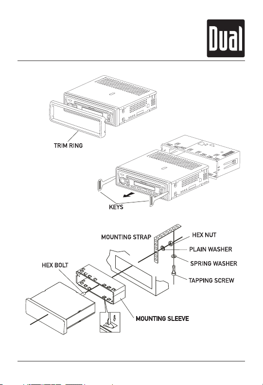
• Remove 2 transit screws located on top of the unit.
• Remove trim ring by pulling up gently in the center.
• Insert the supplied keys into the slots as shown, and slide the unit out of the
mounting sleeve.
• Install mounting sleeve into opening, bending tabs to secure.
• Connect wiring harness and antenna.
(consult a qualified technician if you are unsure)
• Certain vehicles may require an installation kit and/or wiring harness
adapter (sold separately).
•Test for correct operation and slide into mounting sleeve to secure.
• Snap trim ring into place.
2
Page 3
XD5110 INSTALLATION
Installation
3
TYPICAL MOUNTING METHOD
Page 4
XD5110 INSTALLATION
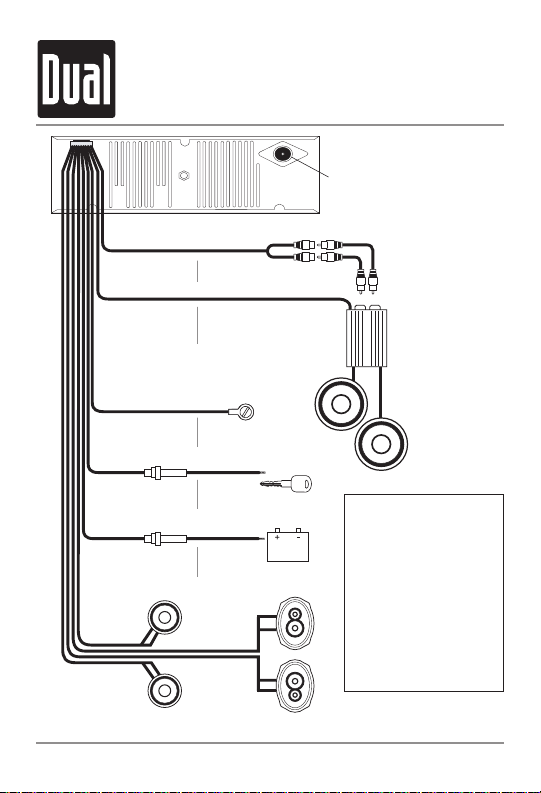
Wiring
Diagram
4
FUSES
When replacing fuses,
make sure new fuse is the
correct type and amperage.
Using an incorrect fuse
could damage the radio.
The XD5110 uses one 1
amp AGC fuse (Ignition)
and one 5 amp AGC fuse
(Battery) located in-line.
* CAUTION - Do not attach any speaker leads to ground as severe damage will occur.
Rear Preamp Output
GRAY
Connect to amplifier RCA Input
Remote Turn-On
BLUE
Connect to amplifier or power
antenna. Insulate wire if not used.
Ground
BLACK
Connect to vehicle
chassis ground.
1 AMP
AGC Fuse
Accessory
RED
Connect to existing ignition
circuit or switched 12 volt source.
5 AMP
AGC Fuse
Memory
YELLOW
Connect to battery
circuit or constant 12 volt source.
Right Front
Gray/Black (-)
Gray (+)
Left Front
White/Black (-)
White (+)
Right Rear
Violet/Black (-)
Violet (+)
Left Rear
Green/Black (-)
Green (+)
Antenna
Connector
RCA Cable
(sold separately)
AMP
Page 5

XD5110 OPERATION
Control Locations
5
Power
Volume
Track Up/Down
Eject
Band
Display
Local/Distance/CD Repeat
Play/Pause
Bass Boost/CD Random
Mono/Stereo/CD Intro
Reset
Audio
Tuning
678910
13
5
1
1
2
3
4
5
6
8
9
10
11
12
13
7
2 3 4
11
12
Page 6

XD5110 OPERATION
6
General Operation
Press PWR to turn the unit on. Inserting a CD will turn
the unit on automatically. Press PWR to turn the unit off.
Insert a CD or press
l
/ IIto begin or resume
playback.
Press PWR or BAND to begin or resume tuner
operation.
Press BASS to activate and deactivate bass boost
curve. Activating this feature will enhance the bass
frequencies when listening to music at low volumes.
Adjust volume using VOL ▲ or VOL▼ (0-63).
Press DISP to display the clock. The radio frequency
(tuner mode) or CD track/elapsed time (CD player
mode) show by default.
Press and hold DISP until the clock begins to flash,
then release. Press TRACK << to adjust the hours and
TRACK >> to adjust the minutes. Press DISP
momentarily to save the selected time.
Power On/Off
CD Mode
Tuner Mode
Bass Boost
Volume
Display
Set the Clock
Page 7

XD5110 OPERATION
General Operation
7
Press and hold for more than 2 seconds to RESET the
unit upon initial installation or if abnormal opeartion
occurs.
Press AUD to select between Volume (default), Bass,
Treble, Balance & Fader.
Press AUD until BAS appears
Press VOLUME ▼ or ▲ to adjust
(7 maximum / -7 minimum)
Press AUD until TRE appears
Press VOLUME ▼ or ▲ to adjust
(7 maximum / -7 minimum)
Press AUD until BAL appears
Press VOLUME ▼ (LEFT) or ▲ (RIGHT) to adjust
(BA.L 10/BA.R 10) BAL 0 represents equal balance.
Press AUD until FAD appears
Press VOLUME ▲ (FRONT) or ▼ (REAR) to adjust
(FA.F 10/FA.R 10) FAD 0 represents equal fader.
Reset
Audio
Bass
Treble
Balance
Fader
Page 8

XD5110 OPERATION
Tuner Operation
8
Tur n TUNE knob to select desired station.
Press MONO during FM tuner operation to select mono
or stereo (default) reception of the broadcast signal.
Press LOC to activate local tuning for strong station
reception only. Press LOC again to cancel and resume
Distance tuning (default).
Press BAND to select between FM and AM bands.
Tuning
FM Mono/Stereo
Local/Distance
Band
Page 9

XD5110 OPERATION
CD Player Operation
9
With the label facing up, insert a standard CD into the
CD slot. The CD will automatically begin playback.
Press the EJECT button to stop and eject the CD. The
unit will change to tuner mode. If the disc is not
removed within 10 seconds, the unit will reload the
disc.
Press TRACK
>> to skip to the beginning of the next
track. Press TRACK
<< to return to the beginning of
the current track. Pressing TRACK
<< again skips to
the beginning of the previous track.
Press and hold TRACK
<< or TRACK >> to fast
forward or reverse a track.
Press
l
/ IIto temporarily stop CD playback.
Press
l
/ IIagain to resume playback.
Press INT to play the first 10 seconds of each track.
Press INT to cancel.
Press RPT to continuously repeat selected track.
Press RPT to cancel.
Press RDM for more than 2 seconds to play all tracks
in random order. Press RDM again for more than 2
seconds to cancel.
Some CD-Rs and CD-RWs may be incompatible with
this unit, depending on media type and recording
method.
Insert CD
Eject CD
Track Select
Fast Forward
and Reverse
Pause
Intro
Repeat
Random
CD-R/CD-RW
Compatibility
Page 10

XD5110 WARRANTY
Limited One-Year Warranty
10
This warranty gives you specific legal rights. You
may also have other rights which vary from
state to state.
Namsung America Inc. warrants this product to
the original purchaser to be free from defects in
material and workmanship, under normal
conditions, for a period of one year from the
date of the original purchase.
Namsung America agrees, at our option, during
the warranty period, to repair any defect in
material or workmanship or to furnish an equal
new or renewed product in exchange without
charges, subject to verification of the defect or
malfunction and proof of the date of purchase.
During the One-Year Warranty Period: For One
Year from the date of purchase, your product
will be replaced with a new, renewed or
comparable product (whichever is deemed
necessary) if it becomes defective or
inoperative. This is done without charge to you.
Replacement products are warranted for the
balance of the original warranty period.
Who is covered? This warranty is extended to
the original retail purchaser for products
purchased and used in the U.S.A., in the 48
contiguous states ONLY.
What is covered? This warranty covers all
defects in material and workmanship in this
product. The following are not covered:
installation/removal costs, damage resulting
from accident, misuse, abuse, neglect, product
modification, improper installation, incorrect
line voltage, unauthorized repair or failure to
follow instructions supplied with the product, or
damage occurring during return shipment of the
product.
What to do? If the product requires warranty
service, you must prepay the initial shipping
charges. DUAL will pay the return shipping
charges if the product is returned to an address
within the USA.
Namsung America Inc.
Attn: Returns Center
21318 64th Ave. South
Kent, WA 98032 U.S.A.
Toll Free: 1-866-626-7863
Exclusion of Certain Damages: This warranty is
exclusive and in lieu of any and all other
warranties, expressed or implied, including
without limitation the implied warranties of
merchantability and fitness for a particular
purpose and any obligation, liability, right, claim
or remedy in contract or tort, whether or not
arising from the company’s negligence, actual
or imputed. No person or representative is
authorized to assume for the company any
other liability in connection with the sale of this
product. In no event shall the company be liable
for indirect, incidental or consequential
damages.
Page 11

XD5110 OPERATION
Specifications
11
Signal-to-noise: >86dB
Frequency response: 20Hz-20kHz
Channel separation @ 1kHz: >65dB
D/A converter: 1 Bit
Tuning range: 87.5MHz-107.9MHz
Usable sensitivity: 12dBf
50dB quieting sensitivity: 16dBf
Stereo separation @ 1kHz: 40dB
Frequency response: 30Hz-13kHz
Tuning range: 530kHz-1720kHz
AM sensitivity: 30uV
Frequency response: 80Hz-2kHz
Total power output: 100 Watts Peak
Power output: 25Wx4 @ 4 ohms, 14.4 VDC
Operating voltage: 11-16 VDC, negative ground
Speaker output impedance: 4~8 ohms
Fuses: 1 amp fast blow AGC, 5 amp fast blow AGC
Dimensions: 7" x 7" x 2" (178 x 178 x 51 mm)
Design and specifications subject to change without notice
CD Player
FM Tuner
AM Tuner
General
Page 12

Namsung America Inc.
21318 64th Ave. South
Kent, WA 98032
Toll Free: 1-866-626-7863
www.dualav.com
©2004 Namsung America, Inc.
EVOK0104-V02
XD5110 OPERATION
Troubleshooting
Problem Cause Action
Unit will not
turn on
(no power)
Yellow or red wire not connected or
incorrect voltage
Check connections for proper
voltage (11~16VDC)
Black wire not connected Check connection to ground
Fuse blown Replace fuse
Unit has power
(but no sound)
Speaker wires not connected Check connections at speakers
One or more speaker wires touching
each other or touching chassis
ground
Insulate all bare speaker wires
from each other and chassis
ground
Unit blows
fuses
Yellow or red wire touching chassis
ground
Check for pinched wire
Speaker wires touching chassis
ground
Check for pinched wire
Incorrect fuse rating Use fuse with correct rating
Excessive
skipping
Unit is not mounted correctly or
backstrap is not secure
Check mounting sleeve and
backstrap support
Physical defect in media
(CD, CD-R or CD-RW)
Check media for scratches
Err appears on
display
Load/Eject operation error Press eject or RESET
 Loading...