

Page 1

PC-LC2 CONSOLE
SOFTWARE PACKAGE
Instruction Manual
Version 1.0
Page 2

Industry Canada NOTICE
Notice:Notice:
Notice: The Industry Canada label identifies certified equipment. This
Notice:Notice:
certification means that the equipment meets certain telecommunications
network protective, operational and safety requirements. Industry Canada
does not guarantee the equipment will operate to the user's satisfaction.
Before installing this equipment, users should ensure that it is permissible
to be connected to the facilities of the local telecommunications company.
The equipment must also be installed using an acceptable method of
connection. The customer should be aware that compliance with the
above conditions may not prevent degradation of service in some situations.
Repairs to certified equipment should be made by an authorised Canadian
maintenance facility designated by the supplier. Any repairs or alterations
made by the user to this equipment, or equipment malfunctions, may
give the telecommunications company cause to request the user to
disconnect the equipment.
User should ensure for their own protection that the electrical ground
connections of the power utility, telephone lines and internal metallic
water pipe system, if present, are connected together. This precaution
may be particularly important in rural areas.
Caution:Caution:
Caution: Users should not attempt to make such connections themselves,
Caution:Caution:
but should contact the appropriate electric inspection authority, or
electrician, as appropriate.
NOTICE:NOTICE:
NOTICE: The Load Number assigned to each terminal device denotes
NOTICE:NOTICE:
the percentage of the total load to be connected to a telephone loop
which is used by the device, to prevent overloading. The termination
on an interface may consist of any combination of devices subject only
to the requirement that the total of the Load Numbers of all the devices
does not exceed 100.
Ringer Equivalence Number: 01Ringer Equivalence Number: 01
Ringer Equivalence Number: 01
Ringer Equivalence Number: 01Ringer Equivalence Number: 01
AVIS: AVIS:
AVIS: L'étiquette de l'Industrie Canada identifie le matériel homologué.
AVIS: AVIS:
Cette étiquette certifie que le matériel est conforme à certaines normes
de protection, d'exploitation et de sécurité des réseaux de
télécommunications. Industrie Canada n'assure toutefois pas que le matériel
fonctionnera à la satisfaction de l'utilisateur.
Avant d'installer ce matériel, l'utilisateur doit s'assurer qu'il est permis de
le raccorder aux installations de l'entreprise locale de télécommunication.
Le matériel doit également être installé en suivant une méthode acceptée
de raccordement. L'abonné ne doit pas oublier qu'il est possible que la
conformité aux conditions énoncées ci-dessus n'empêchent pas la
dégradation du service dans certaines situations.
Les réparations de matériel homologué doivent être effectuées par un
centre d'entretien canadien autorisé désigné par le fournisseur. La
compagnie de télécommunications peut demander à l'utilisateur de
débrancher un appareil à la suite de réparations ou de modifications
effectuées par l'utilisateur ou à cause de mauvais fonctionnement.
Pour sa propre protection, l'utilisateur doit s'assurer que tous les fils de
mise à la terre de la source d'énergie électrique, les lignes téléphoniques
et les canalisations d'eau métalliques, s'il y en a, sont raccordés ensemble.
Cette précaution est particulièrement importante dans les régions rurales.
AVERTISSEMENT: AVERTISSEMENT:
AVERTISSEMENT: L'utilisateur ne doit pas tenter de faire ces raccordements
AVERTISSEMENT: AVERTISSEMENT:
lui-même; il doit avoir recours à un service d'inspection des installations
électriques, ou à un électricien, selon le cas.
L'indice de charge (IC) assigné à chaque dispositif terminal indique,
pour éviter toute surcharge, le pourcentage de la charge totale qui
peut être reccordée à un circuit té;éphonique bouclé utilisé par ce
dispositif. La terminaison deu circuit bouclé peut être constituée de
n'importe quelle combinaison de dispositifs, pourvu que la somme des
indices de charge de l'ensemble des dispositifs ne dépasse pas 100.
Indices d'equivalence de la sonnerie: 01Indices d'equivalence de la sonnerie: 01
Indices d'equivalence de la sonnerie: 01
Indices d'equivalence de la sonnerie: 01Indices d'equivalence de la sonnerie: 01
FCC Compliance Statement
This equipment has been tested and found to comply with the limits for
a Class A digital device, pursuant to Part 15 of the FCC Rules. These
limits are designed to provide reasonable protection against harmful
interference in a commercial environment. This equipment generates,
uses, and can radiate radio frequency energy and, if not installed and
used in accordance with the instruction manual, may cause harmful
interference to radio communication. Operation of this equipment in a
residential area is likely to cause harmful interference in which case the
user will be required to correct the interference at his own expense.
CAUTION: Changes or modification not expressly approved by Sur-
Gard Security Systems Ltd. could void the user's authority to operate the
equipment.
Important Information
This equipment complies with Part 68 of the FCC Rules. On the back of
this equipment is a label that contains among other information, the FCC
registration number of this equipment.
Notification to Telephone Company
Upon request, the customer shall notify the telephone company of the particular
line to which the connection will be made, and provide the FCC registration
number and the ringer equivalence of the protective circuit.
FCC Registration Number: 1VDCAN-35163-AL-N
Ringer Equivalence Number: 01A
Telephone Connection Requirements
Except for the telephone company provided ringers, all connections to
the telephone network shall be made through standard plugs and telephone
company provided jacks, or equivalent, in such a manner as to allow for
easy, immediate disconnection of the terminal equipment. Standard jacks
shall be so arranged that, if the plug connected thereto is withdrawn, no
interference to the operation of the equipment at the customer's premises
which remains connected to the telephone network shall occur by reason
of such withdrawal.
Incidence of Harm
Should terminal equipment or protective circuitry cause harm to the
telephone network, the telephone company shall, where practicable, notify
the customer that temporary disconnection of service may be required;
however, where prior notice is not practicable, the telephone company
may temporarily discontinue service if such action is deemed reasonable
in the circumstances. In the case of such temporary discontinuance, the
telephone company shall promptly notify the customer and will be given
the opportunity to correct the situation.
Changes in Telephone Company Equipment or Facilities
The telephone company may make changes in its communications facilities,
equipment, operations or procedures, where such actions are reasonably
required and proper in its business. Should any such changes render the
customer's terminal equipment incompatible with the telephone company
facilities, the customer shall be given adequate notice to effect the
modifications to maintain uninterrupted service.
General
This equipment should not be used on coin telephone lines. Connection
to party line service is subject to state tariffs.
Ringer Equivalence Number (REN)
The REN is useful to determine the quantity of devices that you may
connect to your telephone line and still have all of those devices ring
when your telephone number is called. In most, but not all areas, the
sum of the REN's of all devices connected to one line should not exceed
five (5). To be certain of the number of devices that you may connect to
your line, you may want to contact your local telephone company.
Equipment Maintenance Facility
If you experience trouble with this telephone equipment, please contact
the facility indicated below for information on obtaining service or repairs.
The telephone company may ask you disconnect this equipment from
the network until the problem has been corrected or until you are sure
that the equipment is not malfunctioning.
U.S. Point of Contact
Digital Security Controls Ltd.
160 Washburn St.
Lockport, NY 14094
Page 3

TABLE OF CONTENTS
INTRODUCTION 1
CONSOLE FEATURES 1
Uploading Support............................................................... 1
SYSTEM REQUIREMENTS 1
INSTALLATION 1
Refer to the PC-LC2/The Reporter Quick Install Guide
THE GRAPHICAL USER INTERFACE 1
The Screens and Windows of the Console Software ......... 1
Login Screen ....................................................................... 1
Main Interface Screen ......................................................... 2
Connect Button ................................................................... 2
Configure Button ................................................................. 2
Refresh Button .................................................................... 3
LED Color Table ..................................................................3
Automatic Refresh............................................................... 3
Debug Option ...................................................................... 3
About Button ....................................................................... 4
Exit Button ...........................................................................4
Change Password ............................................................... 4
MISCELLANEOUS 5
Changing Options................................................................ 5
APPENDIX A: CONFIGURATION OPTIONS 5
GLOSSARY OF TERMS 6
LIMITED WARRANTY
LAST PAGE
Page 4
INTRODUCTION
This document will describe the operation, features and use
of the PC-LC2 Console v1.0 software. This document also
includes examples and pictures taken directly from the
Console program itself.
The following sections will describe how to:
· Program PC-LC2 card options
· How to upload updated code to the cards
CONSOLE FEATURES
LIST OF INCLUDED FEATURES
· Full Windows 95/98/NT 4.0 (or higher) integration.
· Provides the capability to read the options, as well
as change the options.
· Support for the storage and programming of the
PC-LC2 options.
UPLOADING SUPPORT
The Console software provides the main support
route for the System code uploading.
THE GRAPHICAL USER INTERFACE
THE SCREENS AND WINDOWS OF THE
CONSOLE SOFTWARE
The following sections will describe each of the different screens and commands that are contained in the
Console.
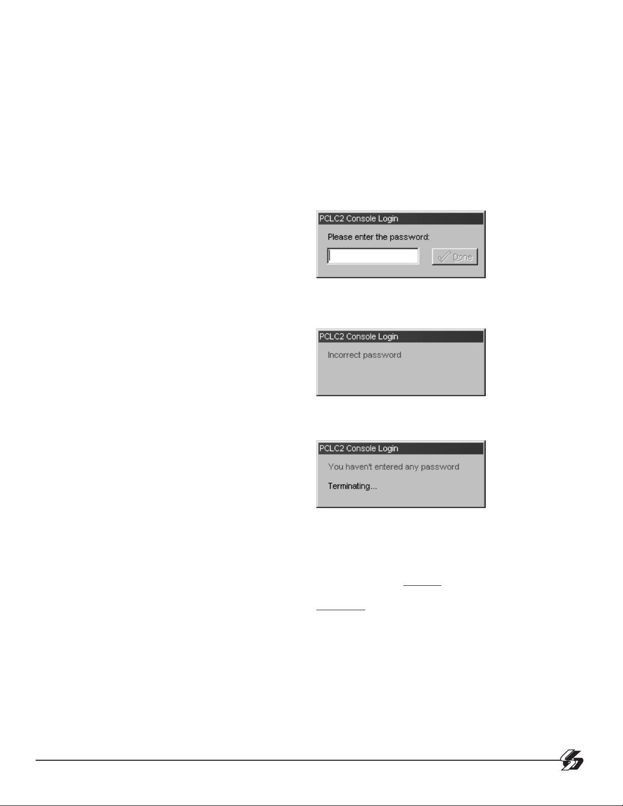
The Login Screen:
This user-input box is the first element of the Console
that is displayed at start-up. The Console will give the
user three chances to enter a valid password.
SYSTEM REQUIREMENTS
The following are the minimum requirements to run the
console, please ensure that these requirements are met:
• Pentium Class Processor at 166MHz with 32MB of
Ram and a 1.0GB hard-drive
• Serial Communications Port, set to 9.6 kbps, 8
data bits, 1 stop bit, no parity, and no hardware
flow control
• Microsoft Windows 95/98/NT 4.0 (or higher) operating system
• A video card and monitor configured to use a
minimum screen resolution of 800x600 pixels, 256
colors
For suggested requirements, the following should
be met:
• PentiumII Class 233MHz CPU, 64MB of Ram with
a 4.0GB hard-drive.
• A larger monitor and video card capable of
1024X768 and 16 Bit (High) Color. This will enable
more viewing space for the message windows and
better color representation of the Console’s
Graphics.
After this is displayed, it will return to the first screen
for the next attempt.
If a valid password is not entered after the third attempt, the Console will terminate itself and shutdown.
The Console has two passwords built into it for distribution. The main password that is distributed with the
Console install files is encrypted in the “console.ini” file.
This password is “cafelatte”. A hard-coded user password that is distributed with the Console software,
“cafeteria”, can be used as a back door in the event
the main password is forgotten. This has the same
access rights as the soft-coded “cafelatte” password.
NOTE: All passwords are case sensitive and must
be entered exactly as described.
INSTALLATION
Please refer to the PC-LC2/The Reporter Quick
Installation Guide.
1
Page 5

THE MAIN INTERFACE SCREEN
NOTE: All portions of the Main Interface Screen are
explained in the following sections.
CONNECT BUTTON
Pressing the connect button establishes the serial connection to the MASTER PC-LC2 card. The same button
turns into the "Disconnect" button once the connection is
established.
CONFIGURE BUTTON
Pressing the configure button opens another window which
allows you to change the serial port settings, (Eg. Com
Port, Parity, Data Bits etc), along with which card is the
MASTER PC-LC2 card.
The second section is the Flow Control:
Here the user can select:
- Hardware Flow Control (handshaking between the Data
Terminal and the Computer Terminal using signal lines)
- Software Flow Control (handshaking between the Data
Terminal and the Computer Terminal using ASCII characters)
- DTR Control (the PC and the data terminal ‘shake hands’
first to assure they are both present)
The Com Port Settings are broken down into three tabbed
sections. The first section is the Base Settings.
Here the user can select:
- Com Port (serial port being used by the PC for communication
to the PC-LC2)
- Speed of communication (Baud Rate)
- Number of Data Bits being sent by the receiver
- Parity (used for error checking of data bits sent)
- Stop Bits (used to determine where one round of data
stops and the next one starts)
The third section is the Device Control:
Here the user can select:
- Device Check (checks signal lines for recipient on other
end before sending/receiving data)
NOTE: the Serial configuration options are defaulted
to the proper settings the 1st time the program is loaded.
The only setting that should be changed in this section is the PC-LC2 Master card, if not on COM3 (default).
2
Page 6

REFRESH BUTTON
The refresh button is used to manually “POLL” all PCLC2 cards in order to display to the user which cards are
currently present in the PC system.
Above is the PC-LC2 Cards display. Each group of 2
LED’s represents 1 PC-LC2 card. The 1st LED of each
pair is Channel A of the card, and the 2nd LED is Channel B. When the Refresh button is pressed, the console
attempts to talk to each Channel of each Card. If the PCLC2 Channel talks to the Console program successfully,
the Console will then wait for the heartbeat from the
Master PC-LC2 card to be received. Once received, the
console will use the Serial status and PBUS status of
each PC-LC2 channel to determine the status and will
change the LED color to reflect this.
LED COLOR TABLE
GREY Channel Not Installed
GREEN PBUS/Serial Comm. To
Channel Working
COM Select: The COM Select item allows you to select
which COMPORT the PC-LC2 Channel is setup to communicate through. Valid selections for this are COM1 to
COM16.
NOTE: The 1st LED should be set to the COM Port
assigned to the master PC-LC2.
Change Options: The change options item allows you to
change the current option settings on the PC-LC2 Channel. See Appendix A.
NOTE: Options can only be set (programmed) when
channel Status Indicators (LEDs) are green.
If the Channel status is GREEN or YELLOW and you
right click over the LED, a popup menu will appear with
options you can select from. (See below)
YELLOW No PBUS Communication
RED No Serial Communication
ORANGE All Comm. To Channel
Lost
BLUE Downloading To Channel
If the Channel status is GREY, RED or ORANGE and you
right click over the LED, a popup menu will appear with
options you can select from (see below).
Refresh: The refresh option works similar to the Manual
Refresh option, except it will only request the Status of
the selected PC-LC2 Channel.
Upload: This option allows you to update your PC-LC2
Channel to another version of the PC-LC2 Code.
Test Number: Selecting this option will cause the Console to ask the PC-LC2 Channel to send it’s current test
number. This is useful for determining if you are running
the most recent code for the PC-LC2.
Set Time&Date: This option allows the user to set the
Time and Date on the PC-LC2 Channel to that currently
set on the PC.
DEBUG OPTION
Pressing this button opens a debug window, which will display messages as to what the program is doing. E.g. report
when refreshing PC-LC2 cards, heartbeat received, etc.
AUTOMATIC REFRESH
The Automatic Refresh works similar to the Manual Refresh button, except that it will automatically refresh the
PC-LC2 channels status every 30 seconds.
3
Page 7

Within the Debug window, if you right click on the mouse,
a popup menu will appear as shown below. On this menu
there are 2 choices. Clear Window and Suppress Hear tbeats. The Clear Window command will clear eve rything
currently displayed in the debug window if it becomes
cluttered.
The Suppress Heartbeats option when turned on will disable the “Heartbeat Received” message from being displayed.
If the console is connected for long periods of time, the
debug window will fill up with several of these messages.
Therefore, enabling this option decrease the Debug traffic.
EXIT BUTTON
Pressing the Exit button will force the Console to
disconnect any active serial connection to the PC-LC2
and then shutdown the Console program itself.
CHANGE PASSWORD
Pressing the Change Password button will open another
window, which will allow you to change the soft-coded
password.
The password must be at least 8 characters, and must
be different from the current password, or the password
change will not work.
ABOUT BUTTON
Pressing this button brings up the Help About screen.
The E-mail and Web addresses displayed on this form
are live hyper-links and will open the user’s default respective application. In the case of the e-mail link, the
default mail program will open a new message with the
address pre-entered and ready for the user to compose
their message. The Console will open the user’s default
Internet browser and connect with the Sur-Gard web-site
when the web hyper-link is clicked.
4
Page 8

MISCELLANEOUS
CHANGING OPTIONS
Changing the PC-LC2 Cards options through the Con-
sole is very easy. Once you select this option, a new
window will open and display all the options available
to change on the PC-LC2 (see below).
Each PC-LC2 Channel can have it’s own saved options
file or even many different saved options files. Through
the file options section, selecting different options files
for the PC-LC2 Channel is easy. Here is displayed the
last options file edited by the user. This file may be
changed by pressing the folder icon to the right hand
side of the filename box.
Next is the Load Defaults button, which allows you to
easily revert back to the factory default settings for the
PC-LC2 Channel. Once editing of a file is finished, you
can click the SaveAs button to save the file to the hard
drive of your PC for later editing.
In the Options listing window, there are 5 columns. The
1st column displays the Option Number, if you double
click on this while the debug window is open, the console will request that the PC-LC2 Channel send what
that Option is currently set to on the selected channel.
The second column displays to the user what the Default Value for the option is. If you double click on this,
you will set the Option to the default value.
NOTE: any changes to options will be displayed in
LIGHT BLUE until the file is saved.
The next column is what the option is currently set to in
the file you opened, these values may be changed by
clicking in the box and typing a HEXADECIMAL value.
Next is the Option Name; this is a quick description
name as to what the option is. And lastly is a Comment,
which describes the Option further.
Once you have decided on what your options should be
set to, you should save your file (so you don’t lose your
changes) then press the SET button. Pressing the SET
button will cause the console to program all the options
on the PC-LC2 Channel that you selected for Options
Editing.
If your Debug window is open, you will see the Console
talking to the Selected PC-LC2 Channel. If you clicked
on the Change Options item while the PC-LC2 Status
LED was RED, GREY, or ORANGE, you will not be able
to press the SET button. This is because the Serial
Communications to the PC-LC2 Channel has been lost
or is not working properly, therefore you cannot communicate to the Channel.
If you clicked on the Change Options item while the PCLC2 Status LED was GREEN or YELLOW, the SET button
will be available.
APPENDIX A: CONFIGURATION OPTIONS
00-07 Handshake #1-8
08 Caller ID Select
09 Printer
0D COM Format
0E COM ACK Wait
0F COM Heartbeat
10 Line Check
11 Buzzer
13 Library
14 Y/S Printer
15 Reciever
16 3/2 Format
17 4-1 Express
18 Online Delay
19-28 3-1, 4-1 Event #0-F
29-38 3-2, 4-2 Event #0-F
39-48 4-3 Event #0-F
49 HS Duration
4A SIA Level II
4B Slave Poll
4C Channel Status
4D Equivalent Line
5
Page 9

GLOSSARY OF TERMS
Console:
A Windows95/98/NT software package that uses serial connected ports between the host
PC / workstation and the PC-LC2 to allow for monitoring and configuration interfaces.
ComPort:
An external or internal 9 pin port used for communication between the Console software
package and PC-LC2.
Master PC-LC2 Card:
This is the main channel that controls the communication of the printer, computer, and PBUS
operation.
Channel:
Every PC-LC2 card has two telephone line inputs/outputs that are designated as Channel
A and channel B.
IRQ:
Interrupt request
COM:
Serial Communication Port
6
Page 10

Limited Warranty
SG Security Communications warrants that for a period of one year from the date of purchase, the product shall be free of defects
in materials and workmanship under normal use and that in fulfillment of any breach of such warranty, SG Security
Communications shall, at its option, repair or replace the defective equipment upon return of the equipment to its repair depot.
This warranty applies only to defects in parts and workmanship and not to damage incurred in shipping or handling, or damage
due to causes beyond the control of SG Security Communications, such as lightning, excessive voltage, mechanical shock, water
damage, or damage arising out of abuse, alteration or improper application of the equipment.
The foregoing warranty shall apply only to the original buyer, and is and shall be in lieu of any and all other warranties, whether
expressed or implied and of all other obligations or liabilities on the part of SG Security Communications. This warranty contains
the entire warranty. SG Security Communications neither assumes, nor authorizes any other person purporting to act on its behalf
to modify or to change this warranty, nor to assume for it any other warranty or liability concerning this product.
In no event shall SG Security Communications be liable for any direct, indirect or consequential damages, loss of anticipated
profits, loss of time or any other losses incurred by the buyer in connection with the purchase, installation or operation or failure
of this product.
Warning
SG Security Communications recommends that the entire system be completely tested on a regular basis. However,
despite frequent testing, and due to, but not limited to, criminal tampering or electrical disruption, it is possible for
this product to fail to perform as expected.
How to Contact Us:
Sales
For information about additional products, please call our sales number: 1-800-418-7618, or e-mail us at
sales@sur-gard.com.
Technical Support
If you have questions or problems when using Sur-Gard products, you can call technical support. If you are
within the United States, Puerto Rico, the U.S. Virgin Islands or Canada, you can get support by dialing
1-800-503-5869 ext.1. If you are outside these areas, please call (416) 665-4494 ext.1, or e-mail us at
support@sur-gard.com.
Internet
Visit our new Sur-Gard WWW site. You will be able to search the Sur-Gard technical information database and
read information about new products. You will also be able to send us your questions. Our World Wide Web
address is http://www.sur-gard.com.
Page 11

© 2000 SG Security Communications
A Division of Sur-Gard Security Systems Ltd.
401 Magnetic Drive, Units 24-28
Downsview, Ontario Canada M3J 3H9
Tel: (416) 665-4494
Fax: (416) 665-4222
The Reporter Specific Toll Free: 1-877-704-7078
www.sur-gard.com
29003593 R001
Printed in Canada
 Loading...