

FCC COMPLIANCE STATEMENT
CAUTION: Changes or modifications not expressly approv ed by Digital Security Controls Ltd. could void your authority
to use this equipment.
This equipment generates and uses radio frequency energy and if not installed and used properly, in strict accordance with
the manufacturer ’s instructions, may cause interference to radio and television reception. It has been type tested and found
to comply with the limits for Class B device in accordance with the specifications in Subpart “B” of Part 15 of FCC Rules,
which are designed to provide reasonable protection against such interference in any residential installation. However,
there is no guarantee that interference will not occur in a particular installation. If this equipment does cause interference to
television or radio reception, which can be determ ined by turning the equipment off and on, the user is encouraged to try to
correct the interference by one or more of the following measures:
•Re-orient the receiving antenna
•Relocate the alarm control with respect to the receiver
•Move the alarm control away from the receiver
•Connect the alarm control into a different outlet so that alarm control and receiver are on different circuits.
If necessary, the user should consult the dealer or an experienced radio/television technician for additional suggestions.
The user may find the following booklet prepared by the FCC helpful: “How to Identify and Resolve Radio/Television
Interference Problems”. This booklet is available from the U.S. Government Printing Office, Washington, D.C. 20402,
Stock # 004-000-00345-4.
Limited Warranty
DSC warrants that for a period of one year from the date of purchase, the product shall be free
of defects in material and workmanship under normal use and that in fulfillment of any breach
of such warranty, DSC shall, at its option, repair or replace the defective equipment upon return
of the equipment to its repair depot. This warranty applies only to defects in materials and
workmanship and not to damage incurred in shipping or handling, or damage due to causes
beyond the control of DSC, such as lightning, excessive voltage, mechanical shock, water damage or damage arising out of abuse, alteration or improper application of the product
.
The foregoing warranty shall apply only to the original buyer, and shall be in lieu of any and all
other warranties, whether expressed or implied and of all other obligations or liabilities on the
part of DSC. This warranty contains the entire warranty. DSC neither assumes responsibility
for, nor authorizes any other person purporting to act on its behalf, to modify or to change this
warranty, nor to assume for it any other warranty or liability concerning this product.
In no event shall DSC be liable for any direct, indirect or consequential damages, loss of anticipated profits, loss of time or any other losses incurred by the buyer in connection with the purchase, installation or operation or failure of this product.
Important!
DSC recommends that the entire system be completely tested on a regular basis. However,
despite frequent testing, and due to but not limited to criminal tampering or electrical disruption, it is possible for this product to fail to perform as expected.
INSTALLATION INSTRUCTIONS
PC5320 Multiple Wireless Receiver Module
The PC5320 connects to the primary Keybus of a control panel* and provides four secondary 4-wire
connections for up to four PC5132 wireless receiver modules. The PC5320 does not provide addi-
tional zones but enables the 32 zones to be distributed over a greater area. The four PC5132
are programmed identically, each programmed zone redundant on the remaining PC5132 modules.
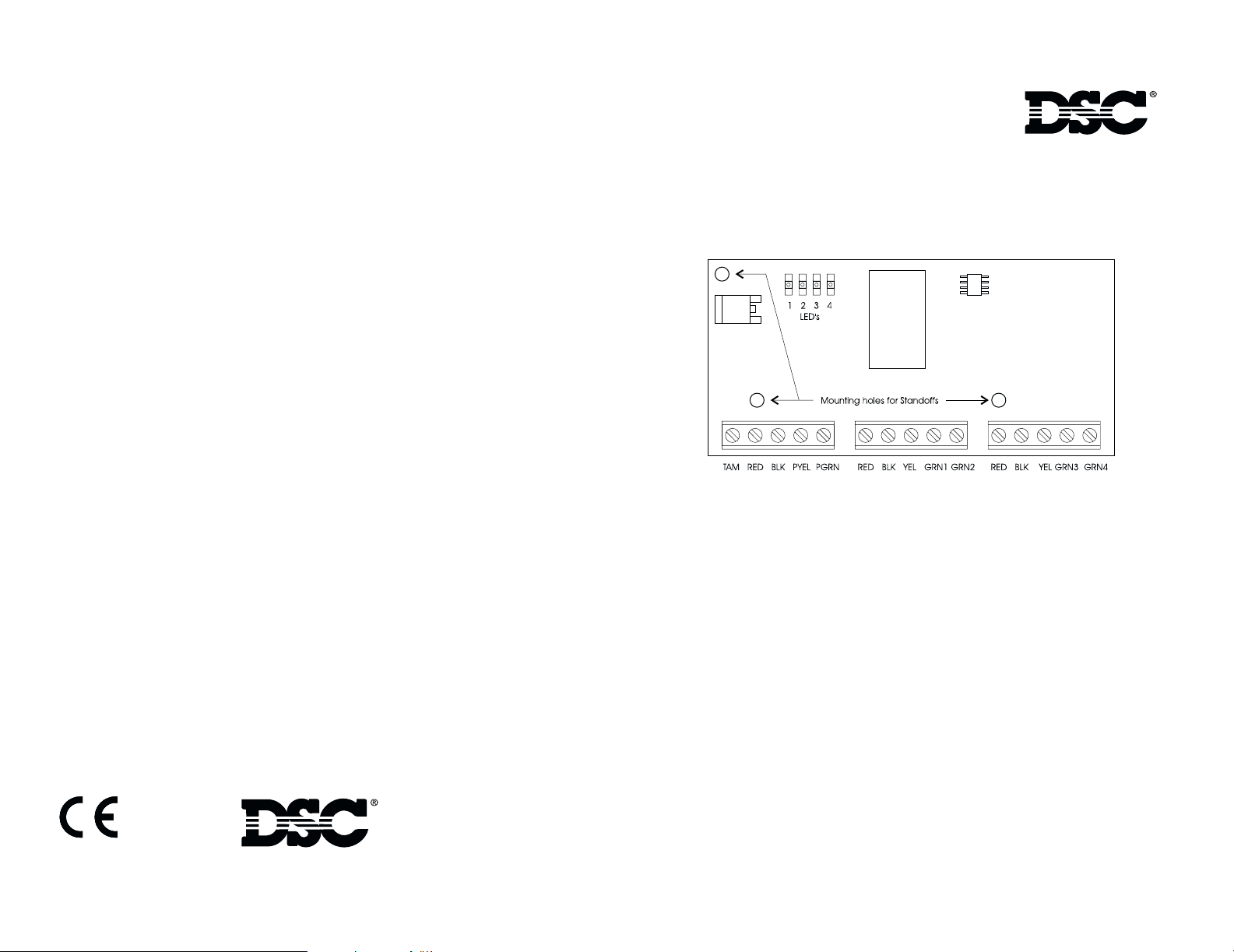
Figure 1 PC5320 Module
SPECIFICATIONS
• Voltage...12 VDC ( NOM)
• Current...55mA, plus current drain of each PC5132
connected.
Compatible Modules
• PC5132-433 v3.00 and up
• LCD5501Z32
Zone Supervision
Each zone is supervised by all PC5132s connected to the PC5320. A zone must be missing from all the
PC5132s before it will send a zone supervision trouble to the control panel. Only one PC5132 is required to
detect a zone and restore the trouble.
Zone Tampers, Violations and Restorals
Zone tampers, violations and restorals are processed by the PC5320. When a PC5132 connected to the
PC5320 detects a tamper, violation or restoral, the PC5320 will send the information to the panel.
*Compatible Control Panels
• PC5008
• PC501x
• PC1555
• PC580
• PC5020
.
©2001 Digital Security Controls Ltd.
Toronto • Canada • 1-800-387-3630 • www.dsc.com
Printed in Canada 29005808 R001
Module Tampers & Troubles
The PC5320 tamper uses the PC5132 tamper slot. When a PC5132 is tampered or has a supervisory trouble
condition the PC5320 sends the tamper/trouble to the control panel and flashes the corresponding Keybus
LED. The panel will log the first PC5132 tamper, and will not log the PC5132 tamper restoral until all
PC5132s are restored. The PC5320 tamper is identical to a PC5132 tamper and must also be restored.
LED Field
The LED field indicates when a PC5132 has been enrolled on a PC5320 bus and indicates when there is a
trouble condition on a PC5320 bus. When a PC5132 is enrolled, the corresponding LED will turn on. For a
trouble condition the corresponding LED will flash. For a PC5320 tamper, the LEDs will remain unchanged.
A fault on a PC5320 bus will cause all LEDs to flash.
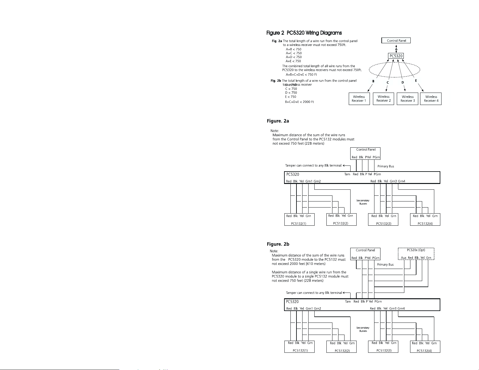
INSTALLATION - Refer to Figures. 1,2 and Control Panel Installation Manual for wiring
details.
1. Select a location - Select a location that ensures that the maximum wire run distances do
not exceed the guidelines indicated in Figure 2. The PC5320 can be mounted in the existing control
panel or a separate plastic housing (Refer to the PC5010 Installation Manual). Locate module so
that service personnel will have easy access to the LED’s for troubleshooting and diagnostics.
2. Remove System Power -
3. Install PC5320 module -
firmly until standoffs ‘click’ into place. Align the module mounting holes over the standoffs and
press module firmly into place. Route the secondary bus wire in accordance with local regulations.
Connect the four secondary busses to the PC5320 module terminals as indicated in Figure 2. Ensure
that the connections to the terminals are secure before applying power. For proper operation there
must be one PC5132 on PC5320 bus #1.
4. Enroll Zones - Refer to the PC5132 Installation Manual to enroll wireless devices. Enroll
each wireless device and then program the zones and partitions as required.
NOTE: The control panel sees the the PC5320 as a single PC5132. Zone programming is passed
through the PC5320 to all PC5132s, to program them identically.
5. Perform Module Placement Test
The module placement test is used to find a location where a PC5132 will reliably receive transmissions from a zone. Perform multiple module placement tests before mounting the unit to
ensure correct placement. While in test mode, the installer can violate the zone more than once
and receive confirmation of the activity. The installer must press [#] on the keypad to end the test.
The PC5320 sends the best result of the module placement test from all PC5132s to the control
panel. For example, if two PC5132s display a ‘Bad Placement’, and one displays a ‘Good Place
ment’, then the PC5320 will send a ‘Good’ indication to the control panel. Only one PC5132 is
required to have a ‘Good’ placement for the device to register as ‘Good’. However, if one PC5132
displays ‘Invalid’, indicating that the zone has not been programmed for that PC5132, the PC5320
will send an ‘Invalid’ result to the panel.
6. PC5132 Programming
If any of the PC5132s enrolled on the PC5320 go into supervisory trouble PC5132 programming
will not be allowed. The supervisory trouble must be restored or the PC5132 removed and the
PC5320’s enrolled field reset as indicated below. Turning on option 1 in section [804] subsection
[97] will cause the PC5320 to reset its module enrolled field. The PC5320 will then turn this bit off.
NOTE If a wireless zone(s) is violated when in Installer Programming, the zone(s) will show as violated when programming is exited. After exiting programming, ensure that the status of all wireless
zones is correct. If a wireless zone indicates it is violated when it is actually secure, the zone must
be violated, then restored to confirm proper zone status..
Insert the three standoffs (provided) into the cabinet. Press
Press [*8] [Install Code] [804] [97] [1] [#] NOTE If a wireless zone(s) is
Default Option ON
OFF
OFF
OFF
OFF
OFF
OFF
OFF
OFF
l___l
l___l
l___l
l___l
l___l
l___l
l___l
l___l
1
Rest 5320 Enrolled Field
2
Not Used
3
Not Used
4
Not Used
5
Not Used
6
Not Used
7
Not Used
8
Not Used
violated when in Installer Programming, the zone(s) will
show as violated when programming is exited. After exiting programming, ensure that
the status of all wireless zones is
correct. If a wireless zone indicates it is violated when it is
actually secure, the zone must
be violated, then restored to
confirm proper zone status.
 Loading...