

DSC PC51O2-433NA Installation Manual

• W A R N I N G •
This manual contains information on limitations regarding
product use and function and information on the limitations as
to liability of the manufacturer.
Installation
Manual
PC51O2-433NA version 1.O
If you are intending to use DLS-3 software with this product, a new DLS-3 driver must
be downloaded from the DSC web site at http://www.dscsec.com/dls3drivers.htm.
Install this driver on your computer in the same directory as your DLS-3 software.

WARNING Please Read Carefully
Note to Installers
This warning contains vital information. As the only individual in contact
with system users, it is your responsibility to bring each item in this warning to the attention of the users of this system.
System Failures
This system has been carefully designed to be as effective as possible.
There are circumstances, however, involving fire, burglary, or other
types of emergencies where it may not provide protection. Any alarm
system of any type may be compromised deliberately or may fail to
operate as expected for a variety of reasons. Some but not all of these
reasons may be:
■■
■ Inadequate Installation
■■
A security system must be installed properly in order to provide adequate protection. Every installation should be evaluated by a security
professional to ensure that all access points and areas are covered.
Locks and latches on windows and doors must be secure and operate
as intended. Windows, doors, walls, ceilings and other building materials must be of sufficient strength and construction to provide the
level of protection expected. A reevaluation must be done during and
after any construction activity. An evaluation by the fire and/or police
department is highly recommended if this service is available.
■■
■ Criminal Knowledge
■■
This system contains security features which were known to be effective at the time of manufacture. It is possible for persons with criminal
intent to develop techniques which reduce the effectiveness of these
features. It is important that a security system be reviewed periodically
to ensure that its features remain effective and that it be updated or
replaced if it is found that it does not provide the protection expected.
■■
■ Access by Intruders
■■
Intruders may enter through an unprotected access point, circumvent
a sensing device, evade detection by moving through an area of insufficient coverage, disconnect a warning device, or interfere with or
prevent the proper operation of the system.
■■
■ Power Failure
■■
Control units, intrusion detectors, smoke detectors and many other
security devices require an adequate power supply for proper operation. If a device operates from batteries, it is possible for the batteries
to fail. Even if the batteries have not failed, they must be charged, in
good condition and installed correctly. If a device operates only by AC
power, any interruption, however brief, will render that device inoperative while it does not have power. Power interruptions of any length
are often accompanied by voltage fluctuations which may damage
electronic equipment such as a security system. After a power interruption has occurred, immediately conduct a complete system test to
ensure that the system operates as intended.
■■
■ Failure of Replaceable Batteries
■■
This system’s wireless transmitters have been designed to provide several years of battery life under normal conditions. The expected battery life is a function of the device environment, usage and type. Ambient conditions such as high humidity, high or low temperatures, or
large temperature fluctuations may reduce the expected battery life.
While each transmitting device has a low battery monitor which identifies when the batteries need to be replaced, this monitor may fail to
operate as expected. Regular testing and maintenance will keep the
system in good operating condition.
■■
■ Compromise of Radio Frequency
■■
(Wireless) Devices
Signals may not reach the receiver under all circumstances which could
include metal objects placed on or near the radio path or deliberate jamming or other inadvertent radio signal interference.
■■
■ System Users
■■
A user may not be able to operate a panic or emergency switch possibly due to permanent or temporary physical disability, inability to reach
the device in time, or unfamiliarity with the correct operation. It is
important that all system users be trained in the correct operation of
the alarm system and that they know how to respond when the system
indicates an alarm.
■■
■ Smoke Detectors
■■
Smoke detectors that are a part of this system may not properly alert
occupants of a fire for a number of reasons, some of which follow. The
smoke detectors may have been improperly installed or positioned.
Smoke may not be able to reach the smoke detectors, such as when the
fire is in a chimney, walls or roofs, or on the other side of closed doors.
Smoke detectors may not detect smoke from fires on another level
of the residence or building.
Every fire is different in the amount of smoke produced and the
rate of burning. Smoke detectors cannot sense all types of fires
equally well. Smoke detectors may not provide timely warning
of fires caused by carelessness or safety hazards such as smoking
in bed, violent explosions, escaping gas, improper storage of flammable materials, overloaded electrical circuits, children playing
with matches or arson.
Even if the smoke detector operates as intended, there may be circumstances when there is insufficient warning to allow all occupants to escape in time to avoid injury or death.
■■
■ Motion Detectors
■■
Motion detectors can only detect motion within the designated areas as shown in their respective installation instructions. They cannot discriminate between intruders and intended occupants. Motion detectors do not provide volumetric area protection. They have
multiple beams of detection and motion can only be detected in
unobstructed areas covered by these beams. They cannot detect
motion which occurs behind walls, ceilings, floor, closed doors,
glass partitions, glass doors or windows. Any type of tampering
whether intentional or unintentional such as masking, painting, or
spraying of any material on the lenses, mirrors, windows or any
other part of the detection system will impair its proper operation.
Passive infrared motion detectors operate by sensing changes in
temperature. However their effectiveness can be reduced when the
ambient temperature rises near or above body temperature or if
there are intentional or unintentional sources of heat in or near the
detection area. Some of these heat sources could be heaters, radiators, stoves, barbeques, fireplaces, sunlight, steam vents, lighting
and so on.
■■
■ Warning Devices
■■
Warning devices such as sirens, bells, horns, or strobes may not
warn people or waken someone sleeping if there is an intervening wall or door. If warning devices are located on a different
level of the residence or premise, then it is less likely that the
occupants will be alerted or awakened. Audible warning devices
may be interfered with by other noise sources such as stereos,
radios, televisions, air conditioners or other appliances, or passing traffic. Audible warning devices, however loud, may not be
heard by a hearing-impaired person.
■■
■ Telephone Lines
■■
If telephone lines are used to transmit alarms, they may be out of
service or busy for certain periods of time. Also an intruder may cut
the telephone line or defeat its operation by more sophisticated means
which may be difficult to detect.
■■
■ Insufficient Time
■■
There may be circumstances when the system will operate as intended, yet the occupants will not be protected from the emergency due to their inability to respond to the warnings in a timely
manner. If the system is monitored, the response may not occur in
time to protect the occupants or their belongings.
■■
■ Component Failure
■■
Although every effort has been made to make this system as reliable as possible, the system may fail to function as intended due
to the failure of a component.
■■
■ Inadequate Testing
■■
Most problems that would prevent an alarm system from operating
as intended can be found by regular testing and maintenance. The
complete system should be tested weekly and immediately after a
break-in, an attempted break-in, a fire, a storm, an earthquake, an
accident, or any kind of construction activity inside or outside the
premises. The testing should include all sensing devices, keypads,
consoles, alarm indicating devices and any other operational devices that are part of the system.
■■
■ Security and Insurance
■■
Regardless of its capabilities, an alarm system is not a substitute
for property or life insurance. An alarm system also is not a substitute for property owners, renters, or other occupants to act prudently to prevent or minimize the harmful effects of an emergency situation.

Thank you for purchasing the PC5102-433 Wireless Receiver. This product will allow
you to connect up to 8 wireless keys to the PC580, P-48, PC1555(MX), P-6B(MX), P-48,
P832/DL, P-8+ and the PowerSeries control panels.
The PC5102-433 operates on the 433 MHz frequency. It provides on-board PGMs
and features a 6-digit serial number for all wireless devices. These new serial numbers
include hexadecimal digits.
Numbers (ESN)” for more information on enrolling 6-digit devices.
We are confident you will find the PC5102-433 wireless receiver a unique and useful
control panel enhancement.
Please read Section 3.1 “A note on Electronic Serial
i

Table of Contents
C O N T E N T S
Introduction 1
1.1 How to Use this Manual ........................................................................1
1.2 Specifications and Features ................................................................. 1
1.3 Compatible Wireless Keys ....................................................................2
1.4 Batteries ................................................................................................ 2
PC5102-433 Set Up & Wiring 3
2.1 Choose a Mounting Location for the PC5102-433 ................................ 3
2.2 Terminal Descriptions ........................................................................... 3
2.3 Connecting the PC5102-433 Receiver ................................................. 4
2.4 Connecting the LED to the PC5102-433 ............................................... 4
2.5 Connecting a Garage Door to the PC5102-433 ................................... 4
2.6 Connecting an X-10 Powerflash Module to the PC5102-433 ............... 5
Enrolling Wireless Keys 6
3.1 A Note about Electronic Serial Numbers ..............................................6
3.2 Enroll & Program Wireless Keys ........................................................... 6
3.3 Identified Wireless Keys ....................................................................... 7
Other Programming 9
4.1 PC5102 PGM Outputs ..........................................................................9
4.2 Enable PC5102-433 Supervision ..........................................................9
4.3 PC5102-433 Software Default ............................................................. 10
4.4 Deleting Wireless Keys .......................................................................10
Testing & Mounting 11
5.1 Test the Reception of Wireless Keys ................................................... 11
5.2 Mount the PC5102-433 .......................................................................11
Additional Notes 12
6.1 Trouble Conditions ..............................................................................12
6.2 Wireless Zone Low Battery Transmission ........................................... 12
Troubleshooting 13
Programming Worksheets 14
Wireless Key Options ................................................................................... 14
Wireless Key Options ................................................................................... 15
Index 17
ii

Introduction
S E C T I O N 1
This manual describes how to install, program and maintain the PC5102-433.
Before you install the PC5102-433 module, you should complete the following steps
in your system installation:
1. Plan the installation and wiring of the security system (see your system
Installation Manual
2. Install the control panel, and install and enroll at least one keypad to use for
programming.
Program the PC5102-433 from a system keypad or using DLS-3 v1.3 with the PC5102433 v1.0 Driver Pack. Read your system
1.1 How to Use this Manual
Read this manual before you begin installing the PC5102-433. To install and set up the
PC5102-433 and wireless keys, follow these steps. Refer to the sections listed below.
1. Temporarily mount and wire the PC5102-433 module (see
2. Enroll and program wireless keys (see
3. Complete PGM and other programming on the system (see
4. Test the placement of all the wireless keys
5. Permanently mount the PC5102-433 receiver
For additional information on trouble conditions and battery replacement, see
Section 6.
For help with troubleshooting, see
1.2 Specifications and Features
• Current Draw: 50mA (standby) 200mA maximum (both outputs active)
• Frequency: 433 MHz
• Receiver can receive signals from up to 8 wireless keys
• Antenna - internal. Installation not required
• Location
- can be wired up to 750 ft/230m. from the main panel with 22 gauge wire
- connects to Keybus
- for longer wire runs, thicker gauge wire must be used
• Compatibility: The PC5102-433 v1.X can be connected to the following
panels: PC501X, P832/DL, PC5020, P-8+, PC1555, P-6B, PC1555MX, P-6BMX,
PC580, P-48
).
Installation Manual
Section 3
(see Section 5).
(see Section 5).
Section 7.
for more information.
).
Section 2
Section 4
).
).
1

I N T R O D U C T I O N
1.3 Compatible Wireless Keys
Please refer to the instruction sheets of the following keys for more information.
The PC5102-433 v1.X can receive signals from the following keys:
• WLS909-433 Wireless Key • WLS919-433 Wireless Key
• PWLS909-433 Wireless Key • PWLS919-433 Wireless Key
1.4 Batteries
The PWLS909-433/WLS909-433 use three A-76 batteries and the PWLS919-433/
WLS919-433 use two CR2032 Lithium batteries.
2

PC5102-433 Set Up & Wiring
S E C T I O N 2
This section describes how to set up and wire the PC5102-433 module.
2.1 Choose a Mounting Location for the PC5102-433
NOTENOTE
NOTE: Mount the PC5102-433 receiver and wireless keys after you have done
NOTENOTE
placement tests with the wireless keys (see sections 5.1 and 5.2).
Find a place that is:
• Dry
• Close to the point of entry
• As high as possible
• Far from sources of interference, including: electrical noise (computers,
televisions and electric motors in appliances and heating and air
conditioning units); large metal objects like heating ducts and plumbing
which may shield the antenna.
Make sure that electrical wires will not run over the antenna of the module when it is
mounted.
When mounting the PC5102-433 in a basement, place the module as high and as
close to the underside of the first floor as possible. The range of the module will be
reduced if the unit is mounted below ground level.
2.2 Terminal Descriptions
The PC5102 has 2 on-board relay outputs which can be used in many different
applications. They can be used to activate LEDs, open garage doors, trigger X-10
devices etc.
NO1 NC1 COM1 NO2 NC2 COM2 RED BLK YEL GRN
NO1 PGM1 Normally Open Relay Contact
NC1 PGM1 Normally Closed Relay Contact
COM1 PGM1 Relay Common Contact
NO2 PGM2 Normally Open Relay Contact
NC2 PGM2 Normally Closed Relay Contact
COM2 PGM2 Relay Common Contact
RED Keybus Power +12V
BLK Keybus Ground
YEL Keybus Clock
GRN Keybus Data
3
S E T U P & W I R I N G
2.3 Connecting the PC5102-433 Receiver
CAUTION:
Connect the PC5102-433 to the four-wire Keybus of the control panel according to
the following diagram.
Remove all power from the system while connecting modules to the Keybus
Control Panel
RED BLK YEL GRN
YEL
BLK
GRN
RED
KEYBUS TO
PC5102
.
After you have completed the wiring, reconnect the power to the security system.
Now
that you have wired the PC5102-433, you should enroll and program the wireless
keys. See Section 3 for instructions.
NOTE: Each control panel may either have a PC5102 or a PC5132 enrolled but not both.
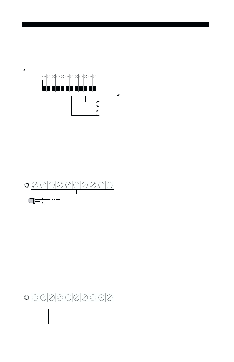
2.4 Connecting the LED to the PC5102-433
The LED can be used to indicate whether the system is armed or disarmed. If the
output is programmed as an armed status output, the red LED will turn on when the
system is armed and will turn off when the system is disarmed.
NC1NO1
RED
BLACK
NC2ANT1 GRNYELBLKREDCOM2NO2COM1
2.5 Connecting a Garage Door to the PC5102-433
Connect an output of the PC5102-433 across the wall-mounted push button or directly
at the motor of the garage door opener (please consult the garage door opener
instructions for proper connections). Set up the system and wireless key so that it is
programmed to pulse an output for a short duration (5 seconds) so that every time the
programmed key is pressed the garage door is opened or closed. The system can also
be set up so that an output on the PC5012-433 will follow a main panel output that is
programmed as a command output and is set up on the wireless key as such. Doing
this will also activate an output on the PC5102-433 for 5 seconds (please refer to the
control panel manual for a listing of available output types and their functions). PGM
1 and/or PGM 2 on the PC5102-433 can be set up to open a garage door (please refer
to Section 4.1).
NC1NO1
NC2ANT1 GRNYELBLKREDCOM2NO2COM1
Garage door
pushbutton
or motor
4
 Loading...