

DSC PC51O Installation Manual

Installation
Manual
• W A R N I N G •
This manual contains information on limitations regarding product use
and function and information on the limitations as to liability of the
manufacturer. The entire manual should be carefully read.
PC51O
Software Version 1.O
®


1
TABLE OF CONTENTS
INTRODUCTION 2
Features ............................................................................................................................................................. 2
Specifications .................................................................................................................................................... 2
INSTALLATION 3
Mounting the Panel ............................................................................................................................................ 3
Mounting the Keypad ........................................................................................................................................ 3
Wiring................................................................................................................................................................. 4
Burglary Zone Wiring......................................................................................................................................... 4
Auxiliary Power Connection............................................................................................................................... 4
PGM Terminal Connections ............................................................................................................................... 4
AC Power Wiring................................................................................................................................................ 4
Battery Connection ............................................................................................................................................ 4
KEY Terminal Connection .................................................................................................................................. 4
KEYPAD FUNCTIONS 5
Introduction........................................................................................................................................................ 5
Master Code ...................................................................................................................................................... 5
Installer’s Programming Code ........................................................................................................................... 5
Arming ............................................................................................................................................................... 5
Auto-Bypass/Home-Away Arming ..................................................................................................................... 5
At-Home Arming ................................................................................................................................................ 5
Disarming........................................................................................................................................................... 6
[
∗
]+[0]: Quick-Arm .......................................................................................................................................... 6
[
∗
]+[1]+[Access Code]: Zone Bypassing ...................................................................................................... 6
[
∗
]+[2]: Display Trouble Conditions............................................................................................. ................... 6
[
∗
]+[3]: Display Alarm Memory ...................................................................................................................... 6
[
∗
]+[4]: Bell Test ............................................................................................................................................. 6
[∗]+[5]+[Master Code]: Program Access Codes........................................................................................... 7
[
∗
]+[6]: Door Chime On/Off ............................................................................................................................ 7
[
∗
]+[7]: Utility Output Command .................................................................................................................... 7
[
∗
]+[8]+[Installer’s Code]: Installer’s Programming Command ..................................................................... 7
[
∗
]+[9]+[Access Code]: At-Home Arming ..................................................................................................... 7
Keypad Zones ................................................................................................................................................... 8
Adjusting the Keypad Sounder Tone and Backlighting .................................................................................... 8
PROGRAMMING GUIDE 9
Section [5]: Enabling System Functions............................................................................................................ 9
Resetting Programming to the Factory Default Settings ................................................................................... 9
PROGRAMMING SECTIONS 10
[1] Zone Definitions ......................................................................................................................................... 10
[2] System Times............................................................................................................................................. 11
[3] Installer’s Code .......................................................................................................................................... 11
[4] Programmable Output Options (PGM1 and PGM2 Terminals) ................................................................. 11
[5] 1st System Option Code ............................................................................................................................ 12
FOR THE RECORD 13
PROGRAMMING WORKSHEET 14
HOOK-UP DIAGRAM 15
LIMITED WARRANTY 16

2
INTRODUCTION
FEATURES
• Fully featured security system with Trouble
Supervision, Alarm Memory, Master Code and 3
programmable Access Codes, Quick-Arming and
At-Home Arming, Door Chime, 3 one-touch Keypad
Zones, and more
• 4 End-of-Line Resistor Supervised Zones
• 6 Programmable Zone Types with Fast and Slow
response times and Silent or Audible alarms
• 2 Programmable Outputs with 9 options
• Momentary or Maintained Keyswitch Arming
• All Installer’s Programming is performed at the
keypad
• EEPROM memory retains all programming even
after all power is removed from the control panel
• Advanced static and lightning protection; unique
“Zap-Trac” circuit board design stops damaging
voltages at the wiring terminals, and transient
protection devices are placed in all critical areas for
further protection
SPECIFICATIONS
PC510 Control Panel
• Four fully programmable zones
• Zones are End-of-Line Resistor supervised
• Maximum zone loop resistance: 100 ohms
• Bell/Siren Output: fused for 5A
• Bell/Siren Alarms: steady and pulsed alarms
• Programmable Output: 50 mA with 9 options
• Auxiliary Power Output:
• 800 mA with 40 VA transformer
• 500 mA with 20 VA transformer
• Maximum 3 Keypads per system and Keyswitch
operation
• Required Battery: 12 V
DC
• 1.2 Ah provides 4 hours of stand-by at
200 mA Auxiliary Output
• 4.0 Ah provides 4 hours of stand-by at
800 mA Auxiliary Output
• Required Transformer: 16 V
AC, 20 - 40 VA
• Panel dimensions: 7" high × 9" wide × 3" deep (178
× 229 × 76 mm)
• Panel Colour: light beige
SL-40 Keypad
• 12-key keypad
• Three one-touch Zones: [F], [A], [P]
• 3 Status Lights: Ready, Armed, System
• 4 Zone Lights
• All new slimline design
• Keypad dimensions: 4.75" high × 2.75" wide × 1.2"
deep (120mm × 70mm × 30mm)
• Keypad Colour: Designer White with Grey display
PC500RK Keypad
• 12-key keypad
• Three one-touch Zones: [F], [A], [P]
• 3 Status Lights: Ready, Armed, System
• 4 Zone Lights
• Nominal current consumption: 30 mA
• Keypad dimensions: 4.5" high × 4.5" wide × 1"
deep (114mm × 114mm × 25.4mm)
• Keypad Colour: Mist
3
INSTALLATION
Mounting the Panel
Select a dry location close to an unswitched AC source and a ground connection.
Remove the printed circuit board, mounting hardware and keypad from the cardboard retainer inside the
control panel cabinet. Before attaching the cabinet to the wall, press the four white nylon printed circuit board
mounting studs into the raised mounting holes from the back of the cabinet. Also, secure the ground screw to
a hole in the cabinet.
Hold the cabinet in position and pull all wires into the cabinet. Mount the cabinet securely to the wall using the
mounting screws provided. It is recommended that appropriate wall anchors be used when securing the panel
cabinet to drywall, plaster, concrete, brick or other similar surfaces.
Press the PC510 Control Panel onto the nylon mounting studs. Pull all cables into the cabinet and prepare them
for connection.
Mounting the Keypad
The PC510 Control Panel is controlled by the SL-40 or PC500RK Keypad. The Keypad should be located close
to the designated “Entry-Exit” door and mounted at a height convenient for all users.
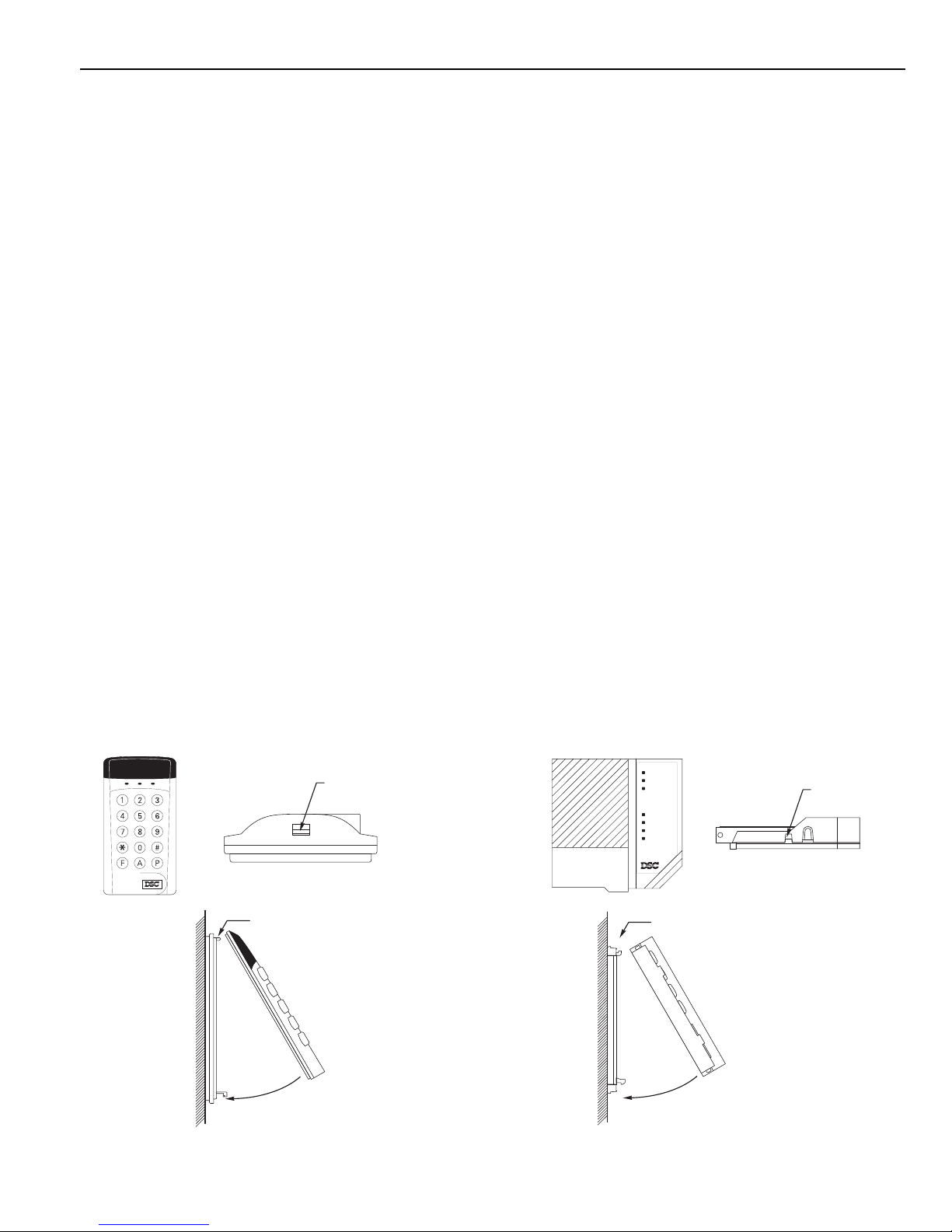
Refer to the illustrations for the keypad included with your control panel. Disassemble the keypad by pressing
gently on the locking tab found on the bottom of the unit. With the tab disengaged, pull the backplate from
the keypad.
Prepare a hole in the wall at the desired location and pull the keypad wiring through the hole. Hold the backplate
in position and pull the wires through the large opening in the backplate. Mount the backplate to the wall using
the hardware provided; it is recommended that plastic wall anchors be used. When mounting the backplate,
ensure that it is straight and level.
Prepare all wires for connection and connect the keypad wires to the in-wall wiring; refer to the Wiring Diagram
in the back of this manual.
Align the keypad with the mounting tabs on the top of the backplate. With the top mounting tabs engaged, swing
the keypad down and engage the bottom locking tab. Ensure that the top mounting tabs and the bottom locking
tab are securely engaged.
LOCKING TAB
SL-40 KEYPAD
BOTTOM VIEW
RE-ASSEMBLY OF
SL-40 KEYPAD
SIDE VIEW
(WIRES NOT SHOWN
FOR CLARITY)
ENGAGE TOP TABS FIRST
SWING KEYPAD DOWN
TO ENGAGE LOCKING TAB
WALL
LOCKING TAB
PC500RK KE YPAD
BOTTOM VIEW
WALL
RE-ASSEMBLY OF
PC500RK KE YPAD
SIDE VIEW
(WIRES NOT SHOWN
FOR CLARITY)
ENGAGE TOP TABS FIRST
SWING KEYPAD DOWN
TO ENGAGE LOCKING TAB
SL-40 Keypad PC500RK Keypad
Zone 1
Zone 2
Zone 3
Zone 4
Armed
System
Ready
1 2 3 4
4
Wiring
NOTE: Complete all wiring to the control panel before applying battery or AC power.
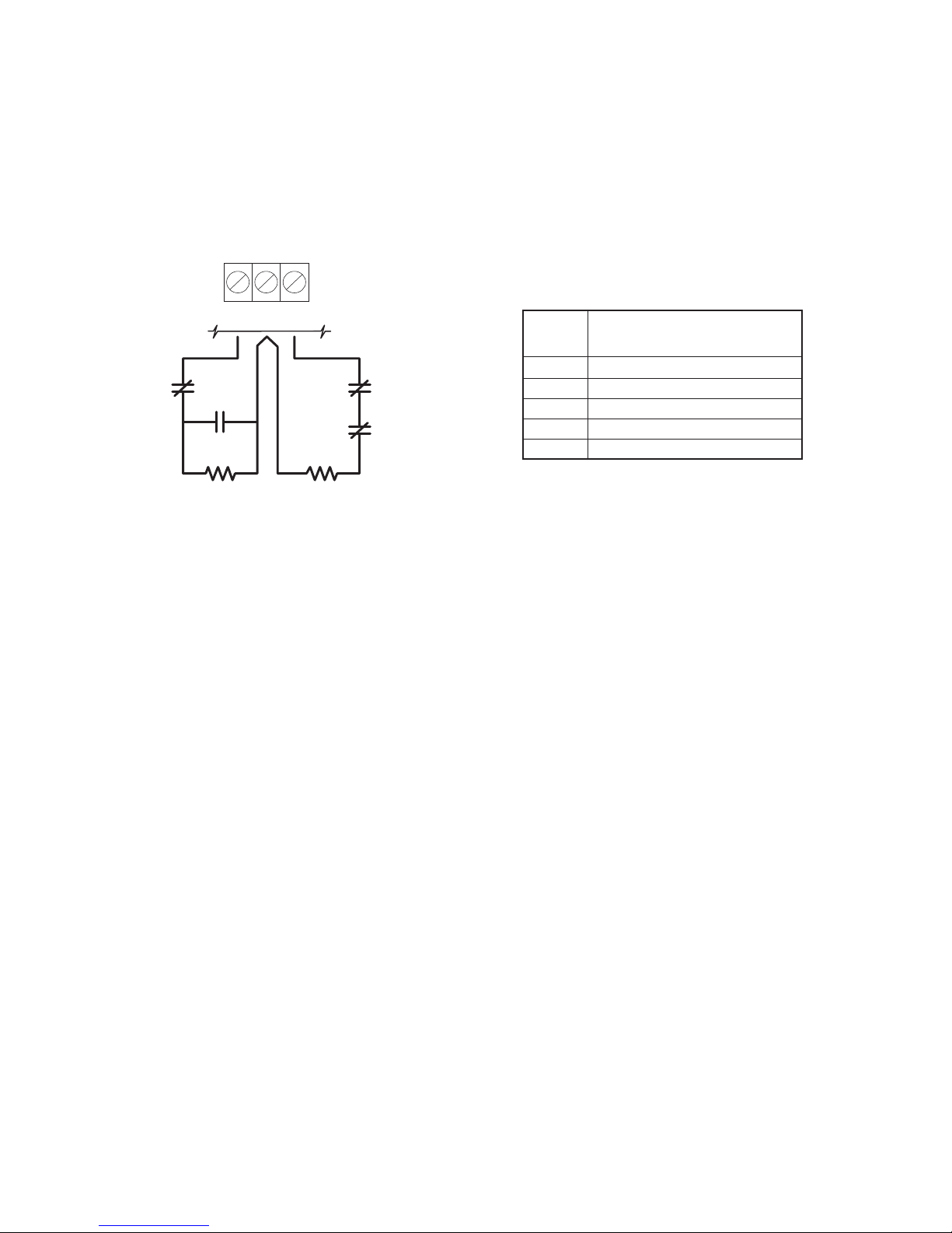
Burglary Zone Wiring
Burglary zone definition, (for example, Delay, Instant, 24-Hour, and so on) is programmed using the keypad.
Refer to Programming Guide Section [1].
Auxiliary Power Connection
The Auxiliary Power Supply can be used to power motion detectors and other devices that require 12 VDC. The
total load for the Auxiliary Power Supply must be calculated for all devices connected across the AUX +/–
terminals and for devices connected between the AUX + and PGM terminals. The output current cannot exceed
800 mA.
PGM Terminal Connections
The PGM terminal is a switched negative output which can be controlled by various programming options; refer
to Programming Guide Section [4]. Devices controlled by the PGM output must be connected between the PGM
terminal and the AUX+ terminal.
AC Power Wiring
Complete all wiring to the control panel before connecting AC power or the battery. The transformer should
not be connected to an outlet that is controlled by a switch.
Battery Connection
If the battery is connected in reverse, the 5 A battery fuse will open and will need to be replaced. The battery
charging voltage is factory set and normally needs no adjustment.
If AC power is OFF and the battery voltage drops to approximately 9.5 V or lower, the battery will be automatically
disconnected and the panel will power down. To power up again, AC power will have to be re-established. This
feature is designed to prevent damage to the battery due to prolonged discharging.
KEY Terminal Connection
The KEY terminal may be programmed for keyswitch operation or for use as a tamper zone. Refer to the
Hook-up Diagram for instructions on wiring the KEY terminal.
Wire
Gauge
1900 / 579
3000 / 914
2400 / 1493
6200 / 1889
7800 / 2377
24
22
20
19
18
Maximum wire length to
End of Line Resistor
(feet/meters)
Figures are based on maximum wiring
resistance of 100 ohms.
Burglary Zone Wiring Chart
Z1
COM Z2
NC
NO
NC
NC
END OF L INE
RESISTOR
5600Ω 0.5W
END OF L INE
RESISTOR
5600Ω 0.5W
EOL RESISTOR
LOOPS USING
NO & NC
DEVICES
EOL RESISTOR
LOOPS USING
NC DEVICES
ONLY
 Loading...