

DSC PC5020 Power864 Installation Manual

IMPORTANT
This manual contains information on limitations regarding product use and function and information on the
limitations as to liability of the manufacturer. The entire manual should be carefully read.
Now classified in accordance with ANSI/SIA CP-01-2000 (SIA-FAR)
Installation
Manual
®
TM
Power 864
SECURITY SYSTEM
PC5O2O/PC5O2OCF Version 3.2
DLS-3 v1.3 and higher

ARNING Please Read Carefully
ote to Installers
his warning contains vital inf ormation. As the only individua l in contact with system users, it is your
esponsibility to bring each i tem in this warni ng to the attention of the users of this syst em.
ystem Failures
his system has been ca refully designed to be as effective as possible. There are ci rcumstances, however,
nvolving fire, burglary, or other types of emergencies where it may not provide protection. Any alarm sysem of any type may be compromised deliberat ely or may fail to operate as expected for a variety of reasons.
ome but not all of these reasons m ay be:
Inadequate Installation
security system mu st be installed properly in order to provide adequ ate protection. Every installa tion
hould be evaluated by a security professional to ensu re that all access point s and areas are covered. Loc ks
nd latches on windows and doors must be secu re and operate as intended. Windows, doors, walls, ceilings
nd other building materials must be of sufficient strength and construction to provide the level of protection
xpected. A r eevaluation must be done during and a fter any construction ac tivity. An evaluation by the fire
nd/or police department is highly recommended if this service is available.
Criminal Knowledge
his system contains security features which were known to be effective at the time of manufacture. It is
ossible for persons with criminal intent to develop techniques which reduce the effectiveness of these feaures. It is important that a security system be reviewed periodically to ensure that its featu res remain effecive and that it be updated or replace d if it is found t hat it does not provide the protection expected .
Access by Intruders
ntruders may enter through a n unprotected access point , circumvent a sensing device, evade detection by
oving through an area o f insufficient coverage, disconnect a war ning device, or interfere with or p revent
he proper operation of th e system.
Power Failure
ontrol units, intrusion d etectors, smo ke detectors and many other security devic es require an adequate
ower supply for proper operation. If a device operat es from batteries, it is possib le for the batteries to fail.
ven if the batte ries have not fai led, they must be charged, in good condition and installed correctly. If a
evice operates only by AC power, any inter ruption, however brief, will render that devic e inoperative whi le
t does not have power. Power inter ruptions of any length are often accompanie d by voltage fluctuations
hich may damage electronic equip ment such as a security system. Af ter a power interruption has occurred,
mmediately co nduct a complete system test to ensu re that the system operates as inten ded.
Failure of Replaceable Batteries
his system’s wireless transmitters have been designed to provide several year s of battery life under normal
onditions. The expected battery life is a function of t he device environmen t, usage and type. Ambient conitions such as high humidity, high or low temperatures, or large temperature fluctuati ons may reduce the
xpected batte ry life. W hile each transmitting device has a low battery mon itor which identifies when the
atteries need to be replace d, this monitor may fail to operate as expected. Regular testing and m aintenance
ill keep the s ystem in good operating condition.
Compromise of Radio Frequency (Wireless) Devices
ignals may not reach t he receiver under all circumstances which could include metal objects p laced on or
ear the radio path or deliberate jamming or other inadvertent r adio signal interference.
System Users
user may not be able to operate a panic or emergency switch possibl y due to permanent or temporary
hysical disability, inability to reach the device in time, or unfamiliarity with the corre ct operation. It is
mportant that all system users be trained in the co rrect operat ion of the alarm system an d that they know
ow to respond wh en the system indicates an alarm.
Smoke Detectors
moke detectors that are a part o f this system m ay not properly alert occupants of a fire for a number of rea-
ons, some of which follow. The smoke detectors may have been improperly installed or positioned. Smoke
ay not be able to reach the smoke detectors, such as when the fire is in a chimney, walls or roofs , or on the
ther side of closed doo rs. Smoke de tectors may not detect smoke from fires on anoth er level of th e resience or building.
very fire is different in the amount o f smoke produced and the rate of burning. Smoke detectors cannot
ense all types of fires equally well. Smoke dete ctors may not provide timely warning of fires caused by
arelessness or safety hazard s such as smoking in bed, violent explosions, escaping gas, improper sto rage of
lammable materials, overloaded electrical circuits, children playing with matches or ars on.
ven if the smoke detector operat es as intended, there may be circumstances w hen there is insufficient warn-
ng to allow all occupants to escap e in time to avoid injury or death.
Motion Detectors
otion detectors can only dete ct motion within the designated areas as shown i n their respective installation
nstructions. Th ey cannot discriminate between i ntruders and inte nded occupants. Motion detectors do not
rovide volumetri c area protection. T hey have multip le beams o f detection and motion can on ly be dete cted
n unobstructed areas covered by these beams. They cannot detect mo tion which occurs behind walls, ceilngs, floor, closed doors, glass partitions, glass doors or windows. Any type of tampering whether intentional
r unintention al such as masking, pa inting, or spraying of any material on the le nses, mirror s, windows or
ny other part of the detection system will impair its proper operation.
assive infrared motion detectors operate by sensing c hanges in temperature. However their effectiveness
an be reduced when the ambient temperature rises near or above body temperature or if ther e are intentional
r unintentional sources of hea t in or near the detection area. Some of these heat sources could be heaters,
adiators, stoves, barbeques, fireplaces, sunlight, steam vents, lighting and s o on.
Warning Devices
arning devices such as sirens, bells, ho rns, or strobes may not warn people or waken someone sleepin g if
here is an int ervening wall or door. If warning devic es are located on a different level of the residence or
remise, then it is less likely that the occupants will be alerted or awake ned. Audible warning devices may
e interfered with by other noise sources such as stereos, ra dios, televisions, air conditioners or other applinces, or pas sing traffic. A udible warning devices, however loud, may not be heard by a hearin g-impaired
erson.
Telephone L ines
f telephone lines are used to transmit alarm s, they may be out of service or busy for cer tain periods of time.
lso an intruder may cut the telephone li ne or defeat its operation by more sophisticated means whi ch may
e difficult to detect .
Insufficient Time
here may be circumstances when the system will operate as inten ded, yet the occupants wi ll not be pr oected from the emergency due to the ir inability to respond to the warnings in a timely manner. If the system
s monitored, the response may not oc cur in time to protect th e occupants or their belongings.
Component Failure
lthough every effor t has been made to make this system as reliable as possible, the system may fail to func-
ion as intended due to the failure of a componen t.
Inadequate Testing
ost problems that would prevent an alarm system from operating as intended can be found by regular test-
ng and maintenance. The complete system shoul d be tested week ly and immediately after a brea k-in, an
ttempted break-in, a fire, a storm, an earthquake, an accident, or any kind of construction activity inside or
utside the premises. T he testing should incl ude all sensing devices, keypads, consoles, alarm indicating
evices and any oth er operation al devices that are part of the system .
Security and Insurance
egardless of its capabilities , an alarm syste m is not a substitute for property or li fe insurance. An alarm sysem also is not a substitute for prope rty owners, renters, or other occupants to act prudently to prevent or
inimize the harmful effects of an emergency situation.
Limited Warranty
Digital Security Controls Ltd. warrants the original purchaser that for a period of twelve months from the
date of purchase, the product shall be free of defects in mate rials and workman ship under normal use. During the warranty period, Digital Security Controls Ltd. shall, at its option, repair or repl ace any defective
product upon return of the product to its factory, at no charge for labour and materials. Any replacement and/
or repaired parts are warranted for the remainder of the original warranty or ninety (90) days, whichever is
longer. The original purchaser must promptly notify Digital Security Controls Ltd. in writing that there is
defect in material or workm anship, such written notice to be received in all events prior to expiration of the
warranty period. Th ere is absolutely no warranty on softw are and all software pr oducts are sold as a user
license under the terms of the software license agreement included with the product. The Customer assumes
all responsibility for the p roper selectio n, installat ion, operation and mainten ance of any pro ducts purchased
from DSC. Custom produ cts are only warranted to the extent that they do not functi on upon delivery. In
such cases, DSC c an replace or credit at its option.
International Warranty
The warranty for international customers is the same as for any customer within Canada and the United
States, with the exception that Digital Security Controls Ltd. shall not be responsible for any customs fees,
taxes, or VAT that m ay be due.
Warranty Procedure
To obtain service under this warranty, please return the item(s) in quest ion to the point of purchase. All
authorized distributors and dealers have a warranty program. Anyone returning goods to Digital Security
Controls Ltd. must first obtain an authorization number. Digital Security Controls Ltd. will not accept any
shipment whatsoever for which prior authorization has not been obtained.
Conditions to Void Warranty
This warranty applies only to d efects in parts and workmanship relating to normal use. It does not cover:
• damage incurr ed in shipping o r handling;
• damage caused by disaster such a s fire, flood, wind, earthquake o r lightning;
• damage due to causes b eyond the control of Digital Security Control s Ltd. such as excessive voltage,
mechanical shock or water damage;
• damage caused by unauthorized a ttachment, alterations, modifications or foreign objects ;
• damage caused by peripherals (unless s uch peripherals were supp lied by Digital Security Controls Ltd.);
• defects cause d by failure to provid e a suitable installation environment for the products;
• damage caused by use of the produ cts for purposes other than those for which i t was designed;
• damage from improper maintenance;
• damage arisin g out of any other abuse, mishandling or improper application of t he products .
Items Not Covered by Warranty
In addition to the items which void the Warranty, the following items shall not be covered by Warranty: (i)
freight cost to the repair centre; ( ii) products which are not identified with DSC's product label and lot number or serial number; (iii) products disassembled or repaired in such a manner as to adversely affect performance or prevent adequate inspection or testing to verify any warranty claim. Access cards or tags returned
for replacement under warranty will be credited or replaced at DSC's option. Products not covered by this
warranty, or otherwise out of warranty due to age, misuse, or damage shall be evaluated, and a repair estimate shall be provided. No repair work will be performed until a valid purchase order is received from the
Customer and a Return Merchandise Authorisation number (RMA) is issued by DSC's Customer Service.
Digital Security Controls Ltd.’s liability for failure to repair the product under this warranty after a reasonable number of attempts will be limited to a replacement of the product, as the exclusive remedy for breach
of warranty. Under no circumstances shall Digital Security Controls Ltd. be liable for any special, incidental,
or consequential damages based upon breach of warranty, breach of contract, negligence, strict liability, or
any other legal theory. Such damages include, but are not limited to, loss of profits, loss of the product or any
associated equipment, cost of capital, cost of sub stitute or replacement equipment, facilities or services,
down time, purchaser’s time, the claims of third parties, including customers, and injury to property. The
laws of some jurisdictions limit or do not allow the disclaimer of consequential damages. If the laws of such
a jurisdiction apply to any claim by or against DSC, the limitations and disclaimers contained here shall be
to the greatest extent permitted by law. Some states do not allow the exclusion or limitation of incidental or
consequential damages, so that the above may not apply to you.
Disclaimer of Warranties
This warranty contains the entire warranty and shall be in lieu of any and all other warranties, whether
expressed or implied (including all implied warranties of merchantability or fitne ss for a particular purpose)
and of all other obligations or liabilities on the part of Digital Security Controls Ltd. Digital Security Controls
Ltd. neither assumes responsibility for, nor authorizes any other person purporting to act on its behalf to modify or to change this warranty, nor to assume for it any other warranty or liability concerning this product. This
disclaimer of warranties and limited warranty are governed by the laws of the province of Ontario, Canada.
WARNING: Digital Security Controls Ltd. recommends that the entire system be completely tested
on a regular basis. However, despite frequent testing, and due to, but not limited to, criminal tampering or electrical disruption, it is possible fo r this product to fail to perform as expected.
Out of Warranty Repairs
Digital Security Controls Ltd. will at its option repair or replace out-of-warranty products which are returned
to its factory according to the following con ditions. Anyone returni ng goods to Digital Security Controls
Ltd. must first obtain an authorization number. Digital Security Controls Ltd. will not accept any shipment
whatsoever for which prior authorization has not been obtained.
Products which Digital Security Controls Ltd. determines to be repairable will be repaired and returned. A
set fee which Digital Security Controls Ltd. has predetermined and which may be revised from time to time,
will be charged for each unit repaired.
Products which Digital Security Controls Ltd. determines not to be repairable will be replaced by the nearest
equivalent product available at that time. The current market price of the replacement product will be
charged for each replacement uni t.

New Features
PC5200 Support
PC5936 Support
SIA FAR
No Activity Arming
(by Partition)
Programmable
Auto-arm Pre-Alert
Timer
Periodic Test
Transmission
Exception
Cross Zoning
True Automatic
Contact ID
The PC5020 v3.1 and higher supports the new PC5200 Power Supply module. See PC5200 Power Supply Output
Module, Pg 2.
The PC5020 v3.1 and higher supports the PC5936 15-station audio matrix module. See PC5936 Audio Interface
Module, Pg 3.
SIA False Alarm Reduction has been incorporated in this version. See the Quick Reference Chart SIA-FAR on the following page.
This feature enables the system (or partition) to arm if there is no zone activity for a programmed time period. See
sections [191]-[198] - No-Activity Timer (Partition 1-8), Pg 30.
The Auto- arm Pre-alert Time is now programmable. The default value for this timer has been extended to 5 minutes.
See Section [199] - Auto-arming Pre-Alert Time, Pg 30.
With this feature enabled, the panel will not send a test transmission if there has been any transmission received by
the receiver within the programmed time. See Section [018] - Sixth System Option Codes, Option 1, Pg 27.
This feature requires two or more trips on a zone(s) specified as “cross zones” within a specified time before starting
an alarm sequence. The Cross Zone option is programmable by zone via Attribute 9. See Section [018], Sixth System Option Codes,Option 6, Pg 28.
When selecting Automatic Contact ID for reporting, the reporting code will represent how a zone is defined according
to the SIA specification for Contact ID. If Automatic Contact ID is enabled, see Appendix A for reporting codes that
will be used for each zone type.
Keypad Buzzer
New Zone Types
Waterflow Silence
Inhibit Option
Verbal Door Chime
and Verbal Alarm
Support
Loop Response
T-Link
When enabled and the system or Partition is in alarm, all assigned keypad buzzers will follow the bell output. When
disabled, the keypad buzzers will only sound for buzzer type alarms. This option is off at default. See Section [018] Sixth System Option Codes, Option 5, Pg 28.
See Sections [001]-[004] - Zone Definitions, Pg 21.
Zone Type 27 - Delayed 24 Hour Waterflow Zone
Zone Type 28 - Instant 24 Hour Waterflow Zone
Zone Type 29 - Auto Verified Fire Zone
Zone Type 30 - Fire Supervisory Zone
Zone Type 31 - Day Zone
This option affects the Instant Waterflow Zone and the Delay Waterflow Zone.
This option does NOT allow the user to silence alarms, manually, automatically, or by a system reset until all waterflow
zones are returned to their restored state. See Section [018] - Sixth System Option Codes, Option 4, Pg 28.
This feature enables the Door Chime to verbally annunciate the Zone that has been violated instead of a series of
beeps. See Section [018] - Sixth System Option Codes, Option 2&3, Pg 33. This feature is only available when using
the ESCORT5580 v3.0, and the PC5936 v1.0. Refer to the Escort5580 v3.0 and PC5936 v1.0 Installation Manuals
for further information.
The PC5020 v3.1 and higher can configure any or all onboard zones for 36 ms Loop Response (see Section [030] Fast Loop Response, Pg 29).
The PC5020 v3.2 supports the T-Link TCP/IP Network Communicator.
i

PC5020 Installer Programming Quick Reference Chart SIA False Alarm Reduction
Minimum requirement system for SIA-FAR Installations :
• 1 PC5020 Control panel
• 2 Local annunciation devices
The local annunciation devices may be any combination of the following keypads.
• LCD5500Z • LCD5501Z
• PKP-LCD • PKP-ICN
The following optional subassembly modules also bear the SIA FAR classification
and may be used if desired:
PC5108 Zone Expander Module
Compatible initiating devices: Bravo200 series, 300 series, 400 series, 500 series,
600 series, AC-100, Encore300 series, Force200 series, 210 series, MN240.
PC5208 Low Current PGM Output Module
The following optional accessory modules also bear the SIA FAR classification and
may be used if desired.
PC5204 Auxiliary Power Supply with PGM output ports
Escort5580/Escort5580TC
PC5400 Printer Module
Section Number Installation
005 5.3 System Times: Access to Entry Delays and Exit Delay for each partition and Bell Time Out for the system.
009 – 011 5.3 Programmable Outputs: Access to PGM Output programming for the main board, PC5208 and PC5204 modules. Output
014, Option 6 5.3 Audible Exit Beeps: Enables beeps from the keypad for the duration of Exit Delay.
018, Option 6 5.3 Cross Zoning: This option enables Cross Zoning for the entire system. Individual zones can be enabled for Cross zoning
018, Option 7 5.3 Exit Delay Restart: Enables the Exit Delay Restart feature.
101 – 164 5.4 Zone Attributes: Access to zone attributes, such as, Audible Bell, Swinger Shutdown, Transmission Delay, and Cross Zone.
176 5.4 Cross Zone Timer: Access to the programmable Cross Zone timer.
304 5.6 Call Waiting Cancel Dialing String: Access to the Dialing sequence used to disable Call Waiting.
th
Entry
328, 6
th
328, 7
Entry
th
328, 8
Entry
st
348, 1
and 2nd Entries
st
377, 1
Entry
th
377, 4
Entry
th
377, 11
Entry
382, Option 2 5.6 Alarm Comms. During Walk Test: Enables Communication of zone alarms while installer Walk Test is active.
382, Option 3 5.6 Communications Cancelled Message: Enables the “Communications Cancelled” message display on all keypads.
382, Option 4 5.6 Call Waiting Cancel: Enables the use of the Call Waiting Cancel string in programmed in Section 304.
901 5.11 Installer Walk Test Mode: Enable/Disable Installer Walk Test mode. This mode can be used to test each zone on the sys-
[*][5] Master Code
33rd and 34th Entries
[*][6] Master Code
Option 4
Manual Section
Attributes in Section in Sections 501 – 514. Partition Assignments in Section 551 – 564.
via Zone Attributes in Sections 101 – 164. Default = OFF
5.6 Cross Zone Reporting Code: Access to the reporting code for Cross Zone Alarm.
5.6 Burglary not Verified Reporting Code: Access to the reporting code for Burglary Not Verified.
5.6 Alarm Cancelled Reporting Code: Access to the reporting code for Alarm Cancelled.
5.6 Walk Test End and Begin Reporting Codes: Access to the reporting codes for Walk Test Begin and Walk Test End.
5.6 Swinger Shutdown for Alarms: Access to the Swinger Shutdown limit for zone alarms.
5.6 Communications Delay: Access to the programmable delay before communicating alarms.
5.6 Communications Cancel Window: Access to the programmable Communications Cancel window.
tem for proper functionality.
4.1 Duress Code: Do not derive code from an existing Master/User code (eg., Master Code is 1234, the duress code should
not be 1233 or 1235.
4.3 System Test: The system activates all keypad sounders, bells or sirens for 2 seconds and all keypad lights turn on. Refer
to the User Manual (part no. 29005909).
Description
Caution
• For SIA FAR installations, only use modules / devices that are listed
on this page.
• Fire Alarm Verification feature (Auto Verified Fire zone) is not supported on 2-wire smoke detectors zones. This feature may be
enabled for 4-wire smoke detectors only.
• Call Waiting Cancel (Section 382 Option 4) feature on a non-Call
Waiting line will prevent successful communication to the central
station.
• All smoke detectors on the system must be tested annually by conducting the Installer Walk Test. Prior to exiting the walk test mode,
a sensor reset must be conducted on the system, [*][7][2] to reset
all latching 4-wire smoke detectors. Please refer to the smoke
detector installation instructions on how to correctly test the detectors.
Notes
• Programming at installation may be subordinate to other UL requirements for the intended application.
• Cross zones have the ability to individually protect the intended area
(e.g., motion detectors, which overlap).
• Cross zoning is not recommended for line security Installations nor is it to
be implemented on exit / entry zones.
• There is a communication delay of 30 seconds in this control panel. It can
be removed, or it can be increased up to 45 seconds at the option of the
end user by consulting with the Installer.
• Do not duplicate any reporting codes. This applies for all communication
formats other than SIA sending automatic programmed reporting codes.
• The control unit must be installed with a local sounding device and an
off-premise transmission for SIA communication format.
ii

Table of Contents
Commercial Burglary, Residential Fire and
Burglary Applications
Commercial Fire Applications
Section 1: Introduction 1
1.1 About the PC5020 System ........................................... 1
1.2 About the PC5020 Manual Set ..................................... 1
1.3 Main Panel Specifications ............................................. 1
1.4 Additional Devices ........................................................ 2
Section 2: Installation and Wiring 5
2.1 Installation Steps .......................................................... 5
2.2 Terminal Descriptions ................................................... 5
2.3 Wire Routing for Power & Non-Power Limited .............. 6
2.4 Keybus Operation and Wiring ....................................... 6
2.5 Current Ratings - Modules & Accessories ...................... 6
2.6 Assigning Zones to Zone Expanders .............................. 7
2.7 Keypad Assignment ...................................................... 7
2.8 Confirming Module Supervision ................................... 8
2.9 Removing Modules ....................................................... 8
2.10 Zone Wiring ................................................................. 8
2.11 Keypad Zones ............................................................. 10
Section 3: How to Program 11
3.1 How to Enter Installer Programming ........................... 11
3.2 Programming Decimal Data ........................................ 11
3.3 Programming Hexadecimal Data ................................. 11
3.4 Programming Toggle Options ..................................... 11
3.5 Viewing Programming ................................................ 12
Section 4: Keypad Commands 13
4.1 Arming and Disarming ............................................... 13
4.2 [*] Commands ........................................................... 14
4.3 Function Keys ............................................................. 17
4.4 Global and Partition Keypad Operation ....................... 18
4.5 Features Available for the LCD5500Z .......................... 18
Section 5: Programming Sections 19
5.1 For the Record............................................................. 20
5.2 Keypad Programming.................................................. 20
5.3 Basic Programming...................................................... 20
5.4 Advanced Programming.............................................. 29
5.5 Partition & Zone Programming ....................................30
5.6 Communicator Programming.......................................31
5.7 Downloading Options..................................................40
5.8 Programmable Output Programming ...........................41
5.9 International Programming .......................................... 42
5.10 Module Programming ..................................................43
5.11 Special Installer Instructions .........................................44
Section 6: Central & Remote Station Fire
Installation Instructions 46
6.1 Introduction ................................................................46
6.2 Hardware Description and Specifications .....................46
6.3 Compatible Devices ....................................................46
Section 7: Fire Monitoring Zone Types 47
7.1 Partitions and Fire System Configuration .....................47
7.2 Fire Zones ...................................................................47
7.3 Auto Verify Fire ........................................................... 47
7.4 Waterflow Zone .......................................................... 47
7.5 PC5700 Zones ............................................................48
7.6 4-wire Smoke Detector Zones .....................................48
7.7 2-wire Smoke Detector Zones .....................................48
7.8 Fire Supervisory Zone ..................................................48
Section 8: Fire System Operation 49
8.1 Manual Signal Silence .................................................49
8.2 Automatic Signal Silence (Bell Time-out) .....................49
8.3 Manual Sensor Reset ([*][7][2]) ................................... 49
8.4 Subsequent Alarm Operation ...................................... 49
8.5 Auto-Scroll LCD Keypad Display ..................................49
8.6 Fire Trouble Conditions ...............................................49
8.7 AC Delays ...................................................................50
8.8 Fire Reporting Codes ..................................................50
Section 9: Listing Requirements 51
9.1 UL Listed Commercial and Residential Installations ......51
9.2 Commercial Fire Monitoring Installations .....................51
9.3 ULC Listing Requirements ...........................................51
Appendix A: Reporting Codes 52
Appendix B: Wiring Diagrams 55
iii
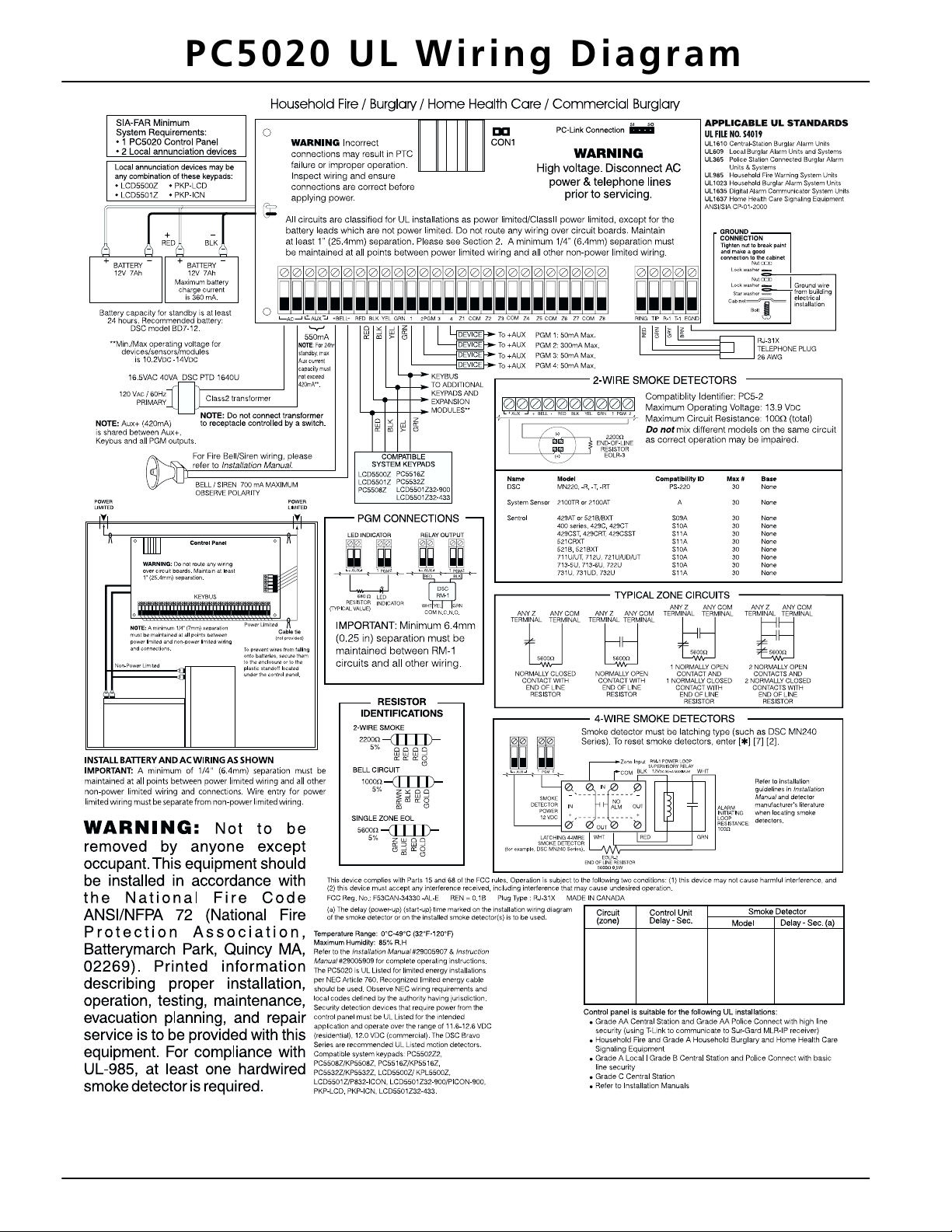
PC5020 UL Wiring Diagram
NOTE: For ULC installations please refer to the ULC Wiring Diagram part #18006238 and the ULC Installation Information
Sheet part #29002157.
iv

Section 1: Introduction
1.1 About the PC5020 System
The PC5020 is a high end security system. It supports up
to 64 zones, 8 separate partitions, and 32 users.
The user interface is simple and easy to use. The
LCD5500Z keypad guides users through their available
options with easy-to-understand prompts.
The status of the PC5020 system can be monitored over
telephone lines, or using an alternative communicating
device, including LINKS1000, LINKS2X50, LINKS3000,
Skyroute™ and DVACS*.
The PC5020 main board comes with 4 programmable outputs, and you can add up to 12 more using PC5204 and
PC5208 modules. You can program the outputs to control
things such as doorstrikes and lights, using 25 different
output options. See ‘Programmable Outputs’ in Section 5.
You can program the PC5020 using any system keypad,
or using DLS-3 downloading software and a computer.
See ‘How to Program’ on page 10.
Review the complete PC5020 manual set before installing
the PC5020 security system
1.2 About the PC5020 Manual Set
Installer Manuals
Read the entire manual carefully before beginning your
installation.
This manual describes:
• An overview of the system (Section 1: ’Introduction’)
• How to install and wire the system and its modules
(Section 2: ’Installation and Wiring’)
• How to program the system (Section 3: ’How to Program’)
• An introduction to the user interface and keypad operation (Section 4: ’Keypad Commands’)
• An overview of the main system programming sections (Section 5: ’Programming Sections’).
Be sure to record all your system programming in the Pro-
gramming Worksheets.
If you will be adding modules to your PC5020 system, read
the Installation Instructions that come with each module.
User’s Guide
One User’s Guide comes with the PC5020 system. The
User’s Guide provides easy to follow instructions for endusers. Installers should also review this manual, in order
to properly instruct the end-users once the installation is
complete.
Commercial Fire Application
Please refer to the Central and Remote Station Fire Installation Guide for information concerning Commercial Fire
applications.
1.3 Main Panel Specifications
Flexible Zone Configuration:
• 8 fully programmable zones
• 39 access codes: 32 user, 1 system master, 2 supervisor
codes, 2 duress, 1 maintenance and 1 installer code
• Expandable to 64 zones
• Keypads with zone inputs available (PC5508Z,
PC5516Z, PC5532Z, LCD5500Z, and LCD5501Z)
• Hardwired expansion available using the PC5108 8zone expansion module, the PC5100 addressable 32
zone expansion module and the PC5700/5720 fire
module
• Wireless expansion available using the PC5132 wireless 32 zone expansion module (433 or 900MHz, fully
supervised)
• Normally closed, Single EOL, or Double EOL zone
supervision
• 34 zone types, 8 programmable zone options
• Up to 8 partitions
Audible Alarm Output:
• 700mA supervised bell output (current limit 3 Amps),
DC
12 V
• Steady or pulsed output
EEPROM Memory:
• Will not lose programming or system status on complete AC and battery failure
Programmable Outputs:
• Up to 14 programmable outputs, 21 programmable
options
• Three low current (50 mA) PGM outputs on main panel
(PGM1, PGM3, PGM4)
• One high current (300 mA) PGM output with 2-wire
smoke detector capability on main panel (PGM 2)
• Eight additional low current (50 mA) PGM outputs
available using the PC5208 module
• Four high current (1 Amp) PGM outputs available using
the PC5204 module (1 PC5204 output, fully supervised
for siren output)
Powerful 1.5 Amp Regulated Power Supply:
• 550 mA auxiliary supply, 12 V
• Positive temperature coefficient (PTC) components
replace fuses
• Supervision for loss of AC power, low battery
• Internal clock locked to AC power frequency
NOTE: For 24-hr standby, maximum Aux capacity is
420mA.
Power Requirements:
• Transformer = 16.0 V
connected
• Battery = (2) 12 volt 7Ah (min.) rechargeable sealed lead
acid
or (1) 12 volt 4Ah battery (for Burglary applications only)
• PC5020 current draw: 65mA
Remote Keypad Specifications:
• Various keypads are available:
- PC5508Z 8 Zone LED keypad
- PC5516Z 16 Zone LED keypad
- PC5532Z 32 Zone LED keypad
- LCD5500Z Liquid Crystal Display keypad
- LCD5501Z LCD-style keypad
- LCD5501Z32-900/LCD5501Z32-433 keypad /
receiver
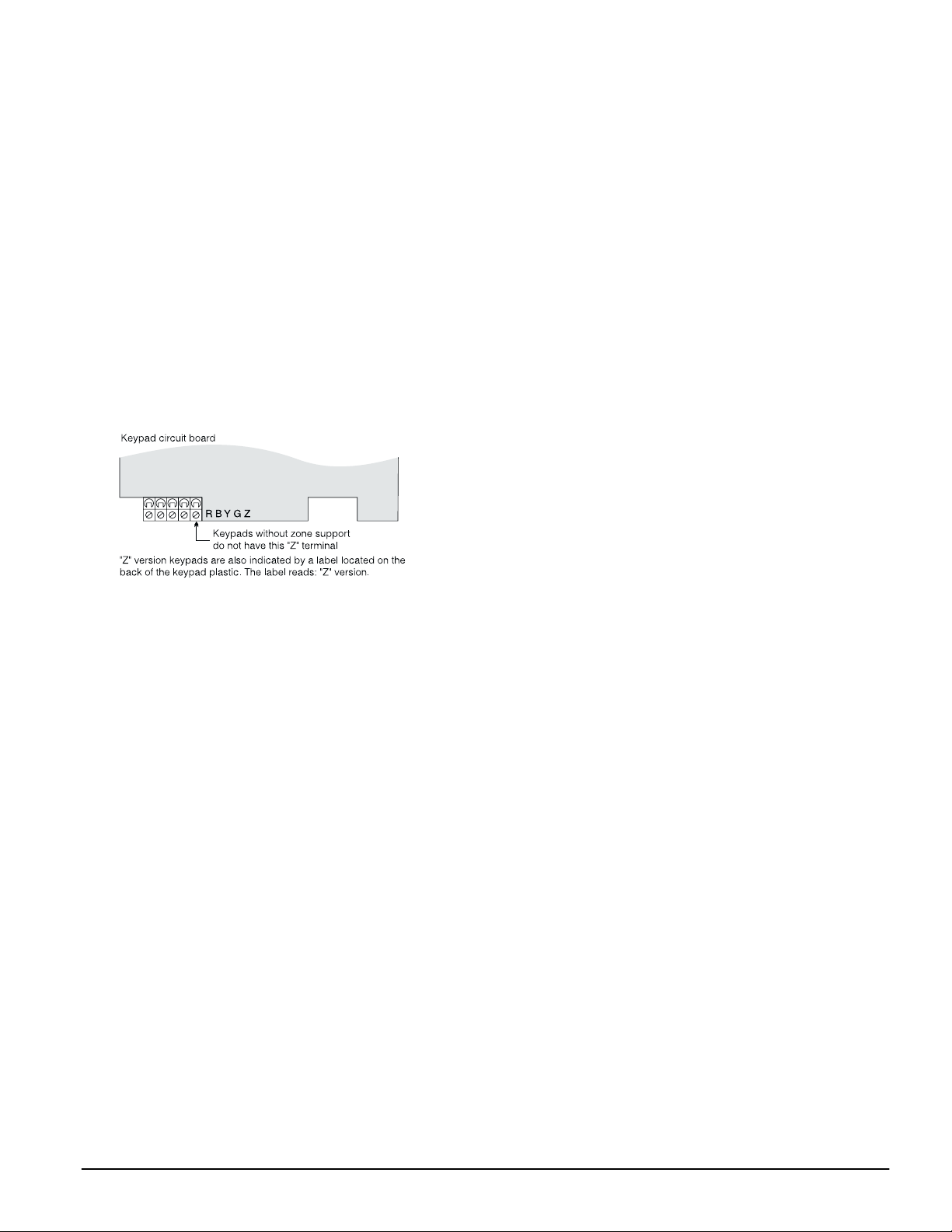
• ’Z’ version keypads have one zone input
• Each keypad has 5 fully programmable function keys
• Connect up to 8 keypads
• Four wire (Quad) connection to Keybus
• Built in piezoelectric buzzer
Digital Communicator Specifications:
• Supports all major formats including SIA, Contact ID,
and Residential Dial
• Split reporting of selected transmissions to each telephone number
DC
AC, 40VA (min) permanently
*DVACS is a registered trademark of Electro Arts Limited.
1

• 3 programmable telephone numbers
• 1 system account number, plus 8 partition account
numbers
• Supports LINKS1000, GSM1000 cellular communication, Links 2X50 long range alarm transmitter and Skyroute™ Cellemetry communication transceiver
• DTMF and pulse dialing
• DPDT line seizure
• Anti-jam detection
• Event-initiated personal paging
• T-Link communications via PC-Link (see T-Link Instal-
lation Manual part no. 29001007)
System Supervision Features
The PC5020 continuously monitors a number of possible
Trouble conditions including:
• AC power failure
• Trouble by zone
• Fire trouble
• Telephone line trouble
• Low battery condition
• Bell output trouble
• Loss of internal clock
• AUX power supply fault
• Tamper by zone
• Failure to communicate
• Module Fault (Supervisory or Tamper)
• Camera Troubles via DLM-4L
False Alarm Prevention Features
• Audible Exit Delay
• Audible Exit Fault
• Urgency on Entry Delay
• Quick Exit
• Swinger Shutdown
• Recent Closing Transmission
• Cross Zone Alarm
• Burglary-verified timer
• Double Hit Timer
• Communication Delay
• Rotating Keypress Buffer
Additional Features
• Automatic arming by partition at a specified time, each
day of the week
• Keypad-activated alarm output and communicator test
• Keypad lockout
• Audio capability using the PC5936 audio interface module; allows local intercom and central station 2-way listen-in
• All modules connect to the system via a four wire Keybus, up to 1000’/305m from the main panel
• Event buffer can be printed using PC5400 RS-232 serial
interface module
• Supports the Escort5580(TC) Voice Prompt Module,
with automation and lighting control
• 256-event buffer, time and date stamped
• Uploading/downloading capability
• Daylight Savings Time option
• Downlook support (DLM-4L v1.0 and PC5108L)
1.4 Additional Devices
In addition to the information below, see the back cover for
a DSC Module Compatibility table.
Keypads
A maximum of 8 keypads can be connected to the control
panel. You can connect any combination of the following
listed. Different keypads (with function keys) can be used
for different size systems: 8 zone, 16 zone, 32 zone, & 64
zone.
• PC5508Z: 8 zone LED keypad, with one zone input
• PC5516Z: 16 zone LED keypad, with one zone input
• PC5532Z: 32 zone LED keypad, with one zone input
• LCD5500Z: LCD keypad, with one zone input
• LCD5501Z: LCD-style keypad, with one zone input
• LCD5501Z32-433: keypad/receiver
NOTE: The following keypad versions can only be used
on the first two partitions (partition 1 and partition 2),
and the first 8, 16, or 32 zones: PC5508(Z), PC5516(Z),
PC5532(Z) v2.00 and lower, LCD5500(Z) versions 2.x and
lower, LCD5501Z versions 1.x and lower
PC5100 2-Wire Addressable Device Interface Module
The PC5100 module is used to connect 2-wire addressable
devices to the system. Up to 32 2-wire addressable devices
can be added to the system.
NOTE: PC5100 v1.0 and lower modules can only support the first 32 zones on the PC5020 system.
PC5108 Eight Zone Expander Module
Eight zone expander module can be used to increase the
number of zones on the system. Up to 7 modules can be
connected to increase the system zones to a maximum of
64 (see the PC5108 Installation Instructions Sheet).
NOTE: PC5108 v1.0 and lower modules can only support
the first 32 zones on the PC5020 system. PC5108 v1.0 and
lower modules enroll as two modules and use up two
supervisory slots.
NOTE: Do not mix PC5108 v1.x and lower modules with
PC5108 v2.0 and higher modules on the same system.
PC5132 Wireless Receiver Module
The PC5132 wireless receiver module can be used to connect up to 32 fully supervised wireless devices (see the
PC5132 Installation Manual for details.)
NOTE: Only the first 32 zones on the PC5020 system can
be used as wireless zones.
PC5200 Power Supply Output Module
The PC5200 can provide up to 1 Amp of additional power
for modules or devices connected to the control panel. Up
to 4 modules can be connected to the system. Each module
requires a 16.5 volt AC 40 VA transformer and 4Ah battery
(see PC5200 Installation Instructions for details).
PC5204 Power Supply Output Module
The PC5204 can provide up to 1 Amp of additional power
for modules or devices connected to the control panel. The
module requires a 16.5 volt AC 40 VA transformer and 4
Ah battery. In addition, the module provides 4 programmable high current voltage outputs. (See PC5204 Installa-
tion Instructions for details).
PC5208 Eight Low Current Output Module
Adds 8 programmable low current outputs (50mA) to the
control (see the PC5208 Installation Instructions for details).
NOTE: If you use the main panel and the PC5208 outputs, PGM 3 will work the same as the first PC5208 output, and PGM 4 will work the same as the second
PC5208 output.
Escort5580(TC) Module
This Escort5580(TC) module will turn any tone telephone
into a fully functional keypad. The module also includes a
built-in interface to control up to 32 line carrier type
devices for lighting and temperature control (see the
Escort5580(TC) Installation Manual for details.)
NOTE: Users will not be able to access partitions 3 to 8,
and zones 33 to 64 through Escort5580(TC) versions 2.x
and lower. Only partitions 1 and 2, and zones 1 to 32
are supported on these versions.
2

Introduction: 1.4 Additional Devices
PC5936 Audio Interface Module
The PC5936 audio interface module provides paging,
intercom, baby listen-in and door answer to the PC5020
control panel. The module has built-in two-way voice
capability for central station (see the PC5936 Installation
Manual for details).
Three additional devices are available:
• PC5921 PKP-ICM Intercom Audio Station can be used in
conjunction with the PC5936 Audio Interface Module.
• PC5921 EXT Door Box Audio Station can be used in
conjunction with the PC5936 Audio Interface Module.
• PC5921 EXT/R Door Box Audio Station can be used in
conjunction with the PC5936 Audio Interface Module.
The Door Box contains a relay so the normal door bell
can be used instead of the internal one generated by the
PC5936 Audio Interface Modules.
PC5400 Printer Module
This PC5400 printer module will allow the panel to print
out all events that occur on the system to any serial
printer. All events will be printed with the partition, time,
date and the event that occurred (see PC5400 Installation
Manual for details).
NOTE: The PC5400 v2.x and lower only supports
events on partitions 1 and 2, and zones 1-32.
LINKS1000 Cellular Communicator
The LINKS1000 Cellular Communicator provides an efficient, cost-effective method for adding cellular back-up.
The unit comes in its own cabinet with antenna and
requires a separate battery and transformer (see Links1000
Cellular Communicator in Section 5).
T-Link Local Area Network Communicator
The T-Link Local Area Network Communicator provides
an efficient method of communicating via a Local Area
Network (LAN). See the T-Link Installation Manual for
more details.
Alternate Communicators
Refer to the associated Installation Manual for LINKS2X50,
LINKS3000, & Skyroute™ programming details.
Downlook Support: PC5108L and DLM-4 v1.0L
The PC5108L will expand the control panel’s zone capability by adding eight fully programmable zone inputs.
The module will also act as an interface between the
DLM-4L v1.0 video transmission module and the PC5020
control panel. The PC5108L is also an 8-camera video
switcher.
For more information on either module, see their respective
Installation Manuals.
NOTE: The PC5108L module can only be assigned zones
from 9 to 32. The PC5108L will not support zones 33 to
64. Camera scripts can only be run for zones 1 to 32. The
PC5108L enrolls as two expander modules and use up
two supervisory slots.
NOTE: Do not mix PC5108L v1.x and lower modules with
PC5108 v2.0 and higher modules on the same system.
PC5700 Fire Module
This is a zone expansion module with four general purpose zone inputs, two Class A supervisory waterflow
zone inputs, ground fault detection and dual-supervised
telephone line inputs.
PC5720 Fire Module
This is a zone expansion fire module that can be used for
ULC Listed non-residential fire applications. The PC5720
can also be used as an interface between the control panel
and either a serial printer or a DVACS communications
network.
NOTE: The PC5700 v1.x and PC5720 v1.x enroll as two
expander modules and use two supervisory slots.
NOTE: Do not mix PC5700 v1.x and PC5720 v1.x and
lower modules with PC5108 v2.0 and higher modules
on the same system.
Cabinets
Several different cabinets are available for the PC5020
modules. They are as follows:
• PC4050C - alternate main control cabinet (Household
Fire & Burglary) for the PC5020 main panel. Dimensions 305mm x 376mm x 125mm / 12.0” x 14.8” x 4.9”
approximately.
• PC4050CR - alternate main control cabinet (Commer-
cial Fire) for the PC5020 main panel. Dimensions
305mm x 376mm x 125mm / 12.0” x 14.8” x 4.9”
approximately.
• PC4050CAR - alternate main control cabinet (Com-
mercial Burglary) for the PC5020 main panel. Dimensions 305mm x 376mm x 125mm / 12.0” x 14.8” x 4.9”
approximately.
• PC4050CRAR - alternate main control cabinet (Com-
mercial Fire and Commercial Burglary) for the PC5020
main panel. Dimensions 305mm x 376mm x 125mm /
12.0” x 14.8” x 4.9” approximately.
• PC500C - alternate main control cabinet (Household
Burglary). Dimensions 213mm x 235mm x 78mm / 8.4”
x 9.25” x 3” approximately.
• PC5002C - cabinet to house the PC5204 power supply
output module. Dimensions 213mm x 235mm x 78mm
/ 8.4” x 9.25” x 3” approximately.
• PC5003C - main control cabinet for the PC5020 main
panel. Dimensions 222mm x 298mm x 78mm / 11.3” x
11.7” x 3.0” approximately (Household Fire & Burglary).
• PC5004C - cabinet to house the Escort5580(TC) module
and PC5400 Printer Module. Dimensions 229mm x
178mm x 65mm / 9” x 7” x 2.6” approximately.
• PC5001C - cabinet to house the PC5108 zone expander
module and the PC5208 8 low current output module.
Dimensions 153mm x 122mm x 38mm / 6” x 4.8” x
1.5” approximately.
• PC5001CP - plastic cabinet to house the PC5108 zone
expander module and the PC5208 8 low current output
module. Dimensions 146mm x 105mm x 25.5mm /
5.75” x 4.2” x 1” approximately.
• CMC-1 - alternate main control cabinet (Commercial
Burglary) Dimensions 222mm x 298mm x 78mm / 11.3”
x 11.7” x 3.0” approximately.
• Multi-3 - cabinet to house the PC5936/PC5937 mod-
ules. Dimensions 287mm x 298mm x 78mm / 11.3” x
11.7” x 3.0” approximately.
• HS-CAB100 - structured wiring cabinet for PC5020
main panel. Dimensions 362mm x 229mm x 102mm /
14.25” x 9” x 4” with a wire raceway positioned on the
right side of the cabinet. The cover is 389mm x 254mm
/ 15.3” x 10”.
• HS-CAB200 - structured wiring cabinet for PC5020 main
panel. Dimensions are 362mm x 362mm x 102mm /
14.25” x 14.25” x 4” with a wire raceway in the center of
the cabinet. The cover is 389mm x 389mm / 15.3” x 15.3”.
• HS-CAB2800 - structured wiring cabinet for PC5020
main panel. Dimensions 724mm x 362mm x 102mm /
28.5” x 14.25” x 4” with a wire raceway in the center of
the cabinet. The cover is 752mm x 387mm / 29.6” x
15.3”.
• HS-CAB4200 - structured wiring cabinet for PC5020
main panel. Dimensions 1086mm x 362mm x 102mm /
42.75” x 14.25” x 4.0” with a wire raceway in the center
of the cabinet.
3

Backplates
There are two different backplates available for keypads
to mount an audio station next to a keypad:
PC55BP1 Backplate
Use this backplate when
mounting an audio station next
to a keypad. Dimensions
208mm x 115mm x 18mm /
8.2” x 4.5” x 0.25” approximately.
PC55BP2 Backplate
Use this backplate when
mounting an audio station
next to a keypad. In addition
the backplate will allow you
to mount a PC5108 zone
expander module or the
module. Dimensions 208mm x 115mm x 18mm / 8.2” x
4.5” x 0.7” approximately.
PC5208 8 low current output
4

Section 2: Installation and Wiring
The following sections provide a complete description of how to wire and configure devices and zones.
2.1 Installation Steps
The following steps are provided to assist with the installation of the panel. It is suggested that you read over this
section briefly to get an overall understanding of the
order of installation. Once this is done carefully work
through each step. Working from this plan will help
reduce problems and reduce the overall installation time
required.
Step 1 Create a Layout
Draw a rough sketch of the building and include all alarm
detection devices, zone expanders, keypads and all other
modules that are required.
Step 2 Mounting the Panel
Locate the panel in a dry area, preferably located near an
unswitched AC power source and the incoming telephone line. Before attaching the cabinet to the wall be
sure to press the five circuit board mounting studs into
the cabinet from the back.
NOTE: Complete all wiring before applying AC or connecting the battery.
Step 3 Wiring the Keybus (Section 2.4)
Wire the Keybus to each of the modules following the
guidelines provided.
Step 4 Assigning Zones to Zone Expanders
(Section 2.6)
If zone expander modules are being used the modules
must be configured so the panel knows which zones are
assigned to each expander. Follow the guideline provided
to assign zones to expanders.
Step 5 Zone Wiring (Section 2.10)
Power down the control panel and complete all zone wiring. Follow the guidelines provided in section 2.10 to connect zones using normally closed loops, single EOL
resistor, double EOL resistors, Fire zones and Keyswitch
Arming zones.
Step 6 Completing Wiring
Complete all other wiring including bells or sirens, telephone line connections, ground connections or any other
wiring necessary. Follow the guidelines provided in section 2.2 ‘Terminal Descriptions’.
Step 7 Power up the Control Panel
Once all zone wiring and Keybus wiring is complete,
power up the control panel.
NOTE: The panel will not power up if only the battery
is connected.
Step 8 Keypad Assignment (Section 2.7)
Keypads must be assigned to different slots to be properly supervised. Follow the guideline provided in section
2.7 to assign keypads.
Step 9 Confirming Module Supervision
(Section 2.8)
By default, all modules are supervised upon installation.
Supervision is enabled at all times so that the panel can
indicate a Trouble if a module is removed from the system.
To confirm that each module is properly supervised, follow the guidelines provided in section 2.8.
Step 10 Programming the System (Sections 4 & 5)
Section 4.0 provides a complete description of how to program the panel. Section 5.0 contains complete descriptions
of the various programmable features, what options are
available and how the options function. The Programming
Worksheets should be filled out completely before attempting
to program the system.
Step 11 Testing the System
Test the panel completely to ensure that all features and
functions are operating as programmed.
2.2 Terminal Descriptions
NOTE: AC Terminals - AC
The panel requires a 16.5 volt, 40 VA transformer. Connect the transformer to an unswitched AC source and
connect the transformer to these terminals.
NOTE: Do not connect the transformer until all other
wiring is complete.
Battery Connection
The battery is used to provide backup power in the event
of an AC power failure and to provide additional current
when the panel demands exceed the power output of the
transformer, such as when the panel is in alarm.
NOTE: Do not connect the battery until all other wiring is complete.
Connect the RED battery lead to the positive of the battery, the BLACK battery lead to the negative.
Auxiliary Power Terminals - AUX+ and GND
These terminals provide up to 550mA of current at 12
DC (rated 11.6-12.6 VDC for UL residential applica-
V
tions) for devices requiring power. Connect the positive
side of any device requiring power to the AUX+ terminal,
the negative side to GND. The AUX output is protected; if
too much current is drawn from these terminals (wiring
short) the panel will temporarily shut off the output, until
the problem is corrected. NOTE: The maximum AUX
capacity for 24-hr standby is 420mA.
Bell Output Terminals - BELL+ and BELL-
These terminals provide up to 3 Amps of current at 12 V
(with standby battery; 700 mA continuous) for powering
bells, sirens, strobes or other warning type equipment.
Connect the positive side of any alarm warning device to
BELL+, the negative side to BELL–. The BELL output is
protected; if too much current is drawn from these terminals (wiring short) the BELL PTC will open.
The bell output is supervised. If no alarm warning device
is being used connect a 1K
BELL– to prevent the panel from displaying a Trouble condition (see section ’[*][2] Trouble Display’).
Keybus Terminals - RED, BLK, YEL, GRN
The Keybus is used by the panel to communicate with
modules and by modules to communicate with the panel.
Each module has four Keybus terminals that must be connected to the four Keybus terminals on the panel. For
more information, see section ’Keybus Operation and
Wiring’.
DC
Ω resistor across BELL+ and
5
Programmable Outputs PGM1, PGM2, PGM3, PGM4
Each PGM output is designed so
that when activated by the panel,
the terminal will switch to ground
PGM1, PGM3, and PGM4 can
each sink up to 50 mA of current.
These PGMs can be used to activate LEDs or a small buzzer. Connect the positive side of the LED
or buzzer to AUX+, the negative
side to the PGM.
PGM2 is a high current output
(300mA) and operates similarly to
PGM1. If more than 300 mA of current is required, a relay must be used. PGM2 can be used
for 2-wire smoke detectors with Jumper CON1 removed,
otherwise, CON1 must remain on at all times (see section
2.10 ‘Zone Wiring‘).
Zone Input Terminals - Z1 to Z8
Each detection device must be connected to a zone on the
control panel. It is suggested that each zone have one
detection device however it is possible to wire multiple
detection devices to the same zone.
For zone wiring specifics, see section ’Zone Wiring’.
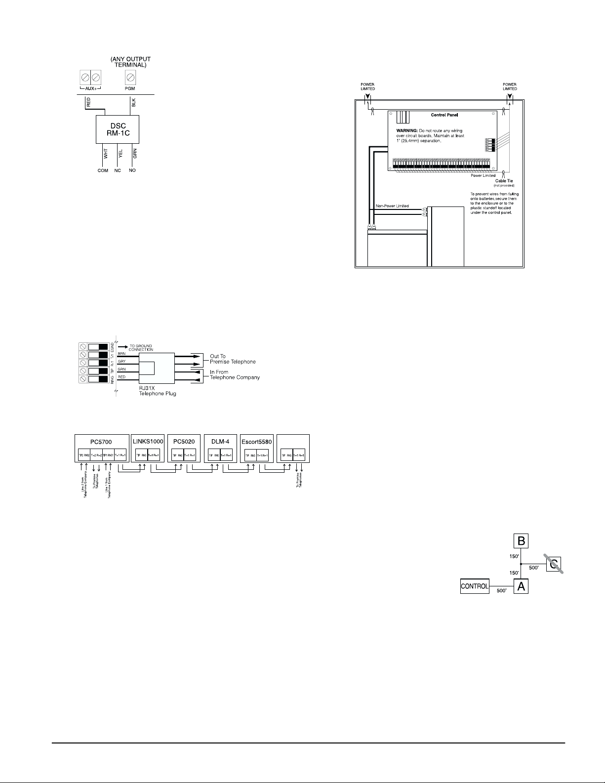
Telephone Connection Terminals - TIP, RING, T-1, R-1
If a telephone line is required for central station communication or downloading, connect an RJ-31X jack in the
following manner:
Connect the PC5020 and modules that use the telephone
line(s) in the following order:
PC5936
For example, if you are installing a PC5020 with a
LINKS1000/GSM1000 and a PC5936 intercom module,
connect the incoming line to the LINKS1000, then from
the LINKS1000 to the PC5020, then from the PC5020 to
the PC5936 audio module and then from the PC5936
module to the house telephones.
NOTE: Ensure that all plugs and jacks meet the dimension, tolerance and metallic plating requirements of 47
C.F.R. Part 68, SubPart F. For proper operation there
must be no other telephone equipment connected
between the control panel and the telephone company facilities.
NOTE: Do not connect the alarm panel communicator
to telephone lines intended for use with a FAX
machine. These lines may incorporate a voice filter
which disconnects the line if anything other than FAX
signals are detected, resulting in incomplete transmissions.
2.3 Wire Routing for Power & Non-Power Limited
All wiring entry points are designated by the arrows. All
circuits are classified UL installation power limited except
for the battery leads which are not power limited.
A minimum ¼” (6.4mm) separation must be maintained
at all points between power limited and non-power limited wiring and connections.
Keybus
NOTE: A minimum 1/4" (6.4mm) separation
must be maintained at all points between
power limited and non-power limited wiring
and connections.
NOTE: Wire entry for power limited wiring must be
separated by a different entry access from non-power
limited wiring.
2.4 Keybus Operation and Wiring
The Keybus is used by the panel to communicate with all
modules connected and by the modules to talk to the
panel. The RED and BLK terminals are used to provide
power while YEL and GRN are clock and data.
NOTE: The 4 Keybus terminals of the panel must be
connected to the 4 Keybus terminals or wires of all
modules.
The following conditions apply:
• Keybus should be run in minimum 22 gauge quad
(0.5mm), two pair twisted preferred
• the modules can be home-run to the panel, connected in
series or can be T-tapped
• any module can be connected anywhere along the Keybus; you do not need a separate Keybus wire run for
keypads, zone expanders etc.
• no module can be more than 1,000'/305m (in wire
length) from the panel
• shielded wire is not necessary unless wires are run in an
area that may present excessive RF noise or interference
Example of Keybus Wiring
Module (A) is wired correctly as it is within 1,000'/
305m of the panel, in wire
distance. Module (B) is
wired correctly as it is
within 1,000'/305m of the
panel, in wire distance.
Module (C) is NOT wired
correctly as it is further than 1,000'/305m from the panel,
in wire distance.
2.5 Current Ratings - Modules & Accessories
In order for the PC5020 system to operate properly, the
power output capabilities of the main control and expansion devices must not be exceeded. Use the data presented below to ensure that no part of the system is
overloaded and cannot function properly.
PC5020 Device Ratings (@ 12 V
• LCD5500Z Keypad: 85 mA
• LCD5501Z Keypad: 45mA
DC)
6
Installation and Wiring: 2.6 Assigning Zones to Zone Expanders
• LCD5501Z32-433 Keypad/Receiver: 260mA (max.)
• PC5100 Addressable Device Interface Module: 40mA
• PC5508Z Keypad: 80 mA
• PC5516Z Keypad: 90 mA
• PC5532Z Keypad: 120 mA
• PC5108 Zone Module: 35 mA
• PC5108L Downlook Interface: 60 mA
• PC5132 Wireless Module: 125 mA
• PC5200 Output Module: 20 mA
• PC5204 Output Module: 20 mA
• PC5208 Output Module: 50 mA
• PC5320 Multiple Receiver Interface Module: 55mA
• Escort5580(TC) Module: 150 mA
• PC5400 Printer Module: 65 mA
• PC5700 Fire Module: 150 mA
• PC5904 Central Station Talk/Listen Module: 175mA
• PC5936 Audio Interface Module: 65 mA
• PC5937 Audio Port Expansion Module: 5mA
• PC5921 Intercom Audio Station: 20 mA
• PC5921 EXT Door Box Audio Station: 20 mA
• PC5921 EXT/R Door Box Audio Station: 35 mA
• DLM-4L v1.0: 180 mA
• T-Link module: 150mA
System Outputs (all 12 V
PC5020 VAUX: 550 mA.
BELL: 700 mA.
PC5200 VAUX: 1.0 A.
PC5204 VAUX: 1.0 A.
PC5208 VAUX: 250 mA.
PC5108 VAUX: 100 mA.
Subtract the listed rating for each keypad, expansion module and accessory connected to VAUX or
Keybus. NOTE: The maximum AUX capacity
for 24-hr standby is 420mA.
Continuous Rating.
3.0 A.
Short Term. Available only with standby battery
connected.
Continuous Rating. Subtract for each device connected.
3.0 A.
Short Term. Available only with standby battery
connected.
Continuous Rating. Subtract for each device connected.
3.0 A.
Short Term. Available only with standby battery
connected.
Subtract for each device connected. Subtract the
total load on this terminal from the PC5020
VAUX/Keybus output.
Subtract for each device connected. Subtract the
total load on this terminal from the PC5020
VAUX/Keybus output.
DC)
Other Devices
Read the manufacturer’s literature carefully to determine
the maximum current requirement (during activation or
alarm) and use this value for loading calculations. Do not
allow connected devices to exceed the system capabilities
during any possible operational mode.
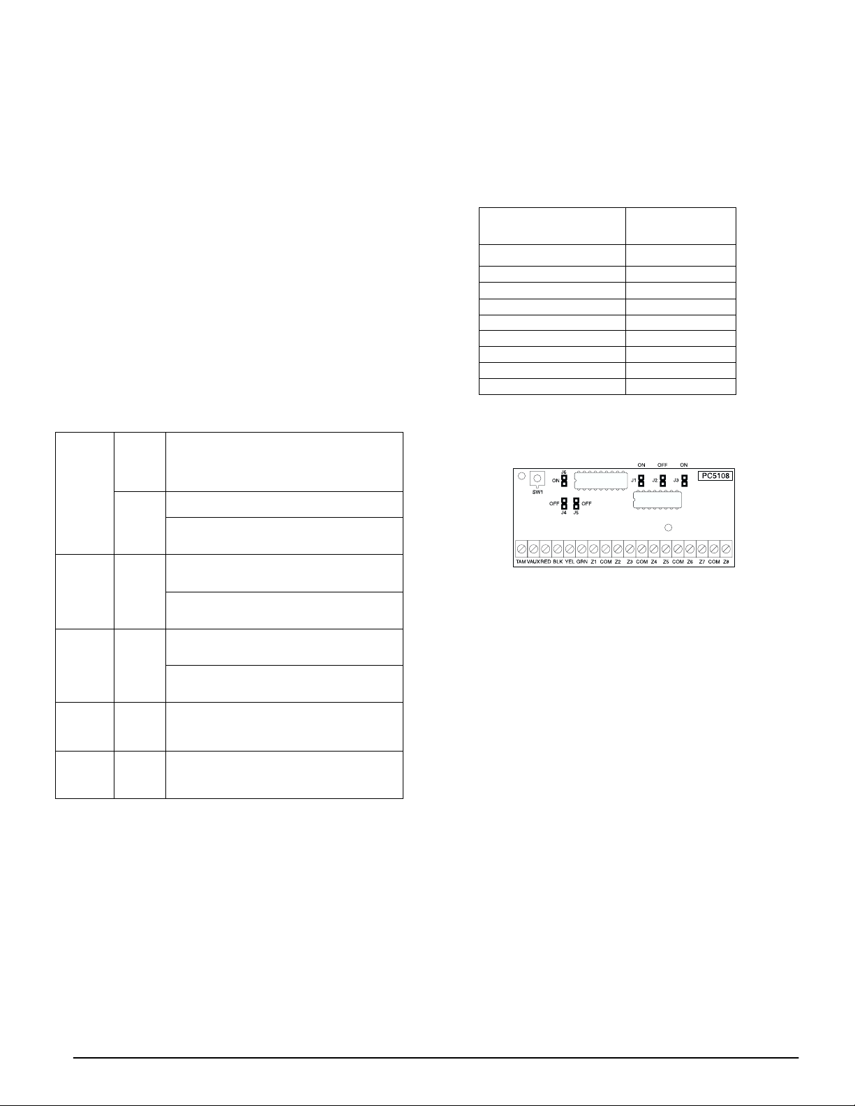
2.6 Assigning Zones to Zone Expanders
The main panel contains zones 1 to 8. Additional zone
expanders may be added to increase the number of zones
on the system. Each zone expander consists of one group
of 8 zones. Each module must be set to assign the specific
zones to the expander. To do this, set the jumpers located
on the expander to the proper settings (see chart below).
NOTE: PC5108 v1.0 and lower modules can only support the first 32 zones on the PC5020 system. PC5108
v1.0 and lower, PC5108L, PC5700, and PC5720 each
enroll as two expander modules.
NOTE: Before a zone expander will work properly, you
must set the jumpers so the panel can determine the
correct zone assignment.
NOTE: It is not recommended to use PC5108 v1.x and
v2.x simultaneously on the same PC5020.
The following are the jumper settings for different zone
assignments for PC5108 v2.0 modules. If you need to
enroll PC5108 v1.0, PC5108L or PC5700 modules, refer to
the appropriate module Installation Sheet for the correct
jumper settings.
Module Jumpers
J1 J2 J3
ON ON ON Zones disabled
OFF ON ON Zones 09 - 16
ON OFF ON Zones 17 - 24
OFF OFF ON Zones 25 - 32
ON ON OFF Zones 33 - 40
OFF ON OFF Zones 41 - 48
ON OFF OFF Zones 49 - 56
OFF OFF OFF Zones 57 - 64
System Zones
Assigned
The following is a diagram of the PC5108 zone expander
modules and where the jumper switches are located. Refer
to the Installation Instructions for the module for more information.
NOTE: Only jumpers J1, J2, and J3 determine the zone
assignment for the module.
2.7 Keypad Assignment
There are 8 available slots for keypads. LED and
LCD5501Z keypads by default are assigned to slot 1. The
LCD5500Z is assigned by default to slot 8. Keypads can
each be assigned to a different slot (1 to 8) which offers
two advantages. The panel can supervise the keypad connection to indicate a Trouble condition if it is removed.
Also keypads can be assigned to operate a specific partition, or to operate as a global keypad.
How to Assign Keypads
NOTE: All keypad assignment must be done at each
keypad on the system. When using LCD5500(Z) keypads, one keypad must remain in slot 8. Do not assign
more than one keypad to the same slot.
NOTE: The following keypad versions can only be used
on partition 1 & partition 2, and the first 8, 16, or 32
zones: PC5508(Z), PC5516(Z), PC5532(Z) versions v2.0 &
lower, LCD5500(Z) versions 3.x and lower. To assign a
keypad to a slot and select the partition it will operate,
enter the following:
1. Enter Installer Programming
2. Press [000] for Keypad Programming
3. Press [0] for Partition and Slot Assignment
4. Enter a two digit number to specify the partition and slot
assignment.
1st digit enter 0 for Global operation, or
enter 1-8 for partitions 1-8
2nd digit enter 1 to 8 for Slot Assignment
5. Press the [#] key twice to exit programming.
7

6. Continue this procedure at each keypad until all have
been assigned to the correct slot and partition.
How to Program Function Keys
Each of the 5 function keys on each keypad may be programmed for different operation.
1. Enter Installer Programming.
2. Press [000] for Keypad Programming.
3. Enter [1] to [5] to select function key to program.
4. Enter a 2-digit number for function key option - [00] to [30].
5. Continue from step 3 until all function keys are programmed.
6. Press [#] key twice to exit Installer Programming.
For a complete list of Function Key options, see section
’Function Keys’.
2.8 Confirming Module Supervision
By default, all modules are supervised upon installation.
Supervision is enabled at all times so that the panel can
indicate a trouble if a module is removed from the system.
To check which modules are currently connected and
supervised:
1. Press [*] [8] [Installer Code] to enter Installer Programming.
2. Press [903] to display all modules.
3. The LCD keypad will allow you to scroll through the
modules.
NOTE: Module supervision will not display correctly at
an LCD5500Z v2.x and lower keypad.
In LED keypads, zone lights will be turned on according
to what modules the panel has found on the system.
Refer to the following chart:
Keypad Light Module/Device Present
[1] Keypad 1
[2] Keypad 2
[3] Keypad 3
[4] Keypad 4
[5] Keypad 5
[6] Keypad 6
[7] Keypad 7
[8] Keypad 8
[9] Zones 9 to 16
[10] Zones 17 to 24
[11] Zones 25 to 32
[12] Zones 33 to 40
[13] Zones 41 to 48
[14] Zones 49 to 56
[15] PC5100
[16] Zones 57 to 64
[17] PC5132
[18] PC5208
[19] PC5204
[20] PC5400
[21] PC5936
[22] LINKS2X50/Skyroute™
[23] DLM-4L v1.0
[24] Escort5580(TC)
[25] Future Use
[26] PC520X-1
[27] PC520X-2
[28] PC520X-3
[29] PC520X-4
If a module is connected but does not show as being
present, it may be due to any of the following reasons:
• it is not connected to the Keybus
• there is a Keybus wiring problem
• the module is more than 1,000'/305m from the panel
• the module does not have enough power
• the PC5132 does not have any devices added
2.9 Removing Modules
If a module is no longer required on the system, the panel
must be told to stop supervising the module. To do this:
1. Remove the module from the Keybus.
2. Press [*] [8] [Installer Code] to enter Installer Programming.
3. Press [902] to enable supervision. The panel will automatically search for all modules on the system, will see
that the module has been removed, and will stop supervising it.
4. Once the search is complete (it will take about 1 minute)
enter section [903] to confirm that the correct modules
are supervised on the system.
2.10 Zone Wiring
For a complete description of the operation of all zone
types, see section ’Basic Programming PWS Sect 3’.
There are several different ways in which zones may be
wired, depending on which programming options have
been selected. The panel can be programmed to supervise
normally closed, end of line, or double end of line loops.
Refer to the following sections to study each type of individually supervised zone wiring.
NOTE: Any zone programmed for Fire or 24-hr Supervisory must be wired with a single end of line (EOL)
resistor regardless of the type of zone wiring supervision selected for the panel (section [013], options [1]
and [2]). See Zone Definitions [001] [004]. If you
change the zone supervision options from DEOL to
EOL or from NC to DEOL (section [013], options [1] or
[2]), power the system down completely, and then
power it back up for correct operation.
Normally Closed (NC) Loops
To enable normally closed loops, programming section
[013], option [1] must be ON.
NOTE: This option should only be selected if Normally
Closed (NC) devices/contacts are being used.
ANY Z
TERMINAL
Normally Closed Loops. . . . . . . . . . . . . . . Section [013], Option [1]
ANY COM
TERMINAL
Single End Of Line (EOL) Resistors
To enable panel detection of single end of line resistors,
programming section [013], options [1] and [2] must be
OFF.
NOTE: This option should be selected if either Normally Closed (NC) or Normally Open (NO) detection
devices or contacts are being used.
ANY Z
TERMINAL
ANY COM
TERMINAL
8
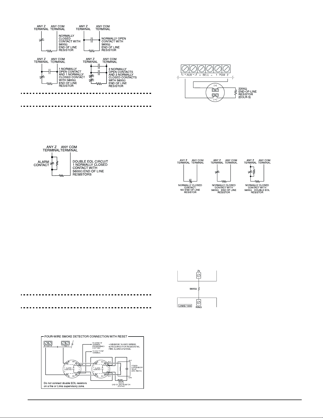
End of Line Resistors . . . . . . . . . . . . . . . . Section [013], Option [1]
Single End of Line Resistors . . . . . . . . . . . Section [013], Option [2]
Double End of Line (DEOL) Resistors
Double end of line resistors allow the panel to determine
if the zone is in alarm, tampered or faulted.
To enable panel detection of double end-of-line resistors,
programming section [013], option [1] must be OFF and
option [2] must be ON.
Installation and Wiring: 2.10 Zone Wiring
For a complete description of how fire zones operate, see
section ’Basic Programming PWS Sect 3’.
Fire Zone Wiring - 2-wire Smoke Detectors
If PGM2 has been programmed for 2-wire smoke detector
connection (see section ’Basic Programming PWS Sect 3’),
the detectors must be wired according to the following
diagram:
NOTE: If PGM2 is programmed for 2-wire smoke support, Jumper CON1 on the main board must be
removed.
For a complete description of how fire zones operate, see
section ’Basic Programming PWS Sect 3’.
Keyswitch Zone Wiring
Zones may be programmed to be used as keyswitch arming zones and must be wired according to the following
diagram:
NOTE: If the double EOL supervision option is
enabled, all hardwired zones must be wired for double
EOL resistors, except for Fire and 24-hr Supervisory
zones.
Do not wire DEOL resistors on keypad zones.
Do not use DEOL resistors for Fire zones or 24-hr
Supervisory zones. Do not wire Fire zones to keypad
zone terminals if the DEOL supervision option is
selected.
This option can only be selected if Normally Closed
(NC) detection devices or contacts are being used. Only
one NC contact can be connected to each zone.
The following chart shows zone status under certain conditions:
Loop Resistance Loop Status
0Ω (shorted wire, loop shorted) Fault
5600Ω (contact closed) Secure
Infinite (broken wire, loop open) Tamper
11200Ω (contact open) Violated
End-of-Line Resistors . . . . . . . . . . . . . . . . Section [013], Option [1]
Double End-of-Line Resistors . . . . . . . . . . Section [013], Option [2]
Fire Zone Wiring - 4-wire Smoke Detectors
All zones defined as Fire (see section ’Basic Programming
PWS Sect 3’) must be wired according to the following
diagram:
For a complete description of how keyswitch zones operate, see section ’Basic Programming PWS Sect 3’.
LINKS1000 Supervisory (24-hr Supervisory)
When using the LINKS1000 cellular communicator, any
main board zone may be configured for LINKS1000 Supervision. Program this zone as zone type (09), 24-hr Supervisory in section [001].
With a 24-hr Supervisory zone, if the LINKS1000 experiences a trouble, the zone will be violated, causing the
panel to report the event to the central station. This type
of zone always requires a single EOL resistor
(5600Ω).Refer to LINKS 1000 Installation Manual wiring
diagram for installation.
LINKS1000 Answer
If the LINKS1000 cellular communicator is being used a zone may
be configured for LINKS1000
Answer to allow downloading to
be performed in the event of telephone line failure. When the
LINKS1000 receives a telephone
call it will activate the RING terminal on the LINKS1000 circuit board. This terminal can be
used to violate a zone programmed as (24) LINKS1000
Answer (see section ’Basic Programming PWS Sect 3’),
causing the panel to seize the telephone line and begin
communication with the downloading computer.
The zone programmed as LINKS1000 Answer ALWAYS
requires a single EOL resistor (5600Ω) and must be wired
according to the diagram above.
NOTE: The LINKS1000 Answer zone is only required
for downloading to the panel via the LINKS1000, or
for remotely connecting to the Escort5580(TC) module
via the LINKS1000.
NOTE: When using the LINKS1000, Busy Tone Detection must not be used.
9
NOTE: Keypad zones cannot be used for 24-hr Supervisory or LINKS1000 Answer.
LINKS 2X50/LINKS 3000/Skyroute™
Refer to the LINKSX50, LINKS3000 and Skyroute™
Installation Manuals for wiring and installation details.
2.11 Keypad Zones
Keypads with zone inputs can be connected to devices
such as door contacts. This saves you from running wires
back to the control panel for every device.
To install the keypad, open the keypad plastic by removing the screw at the bottom of the unit. Locate the five terminals on the keypad circuit board. Connect the four
Keybus wires from the control panel: the red wire to R,
the black to B, the yellow to Y and the green to G.
To connect the zone, run one wire to the Z terminal and
the other to B. For powered devices, use red and black to
supply power to the device. Run the red wire to the R
(positive) terminal and the black wire to the B (negative)
terminal.
When using end of line supervision, connect the zone
according to one of the configurations outlined in section
2.10 ‘Zone Wiring‘.
NOTE: End of line resistors must be placed on the
device end of the loop, not at the keypad.
NOTE: Keypad zones do not support DEOL resistors.
Assigning Keypad Zones
When using keypad zone inputs, each input used must be
assigned a zone number in Installer Programming.
First, ensure that you have enrolled all installed keypads
into the desired slots (see section ’Keypad Assignment’).
Next, enter programming section [020] to assign the
zones. There are eight programming locations in this section, one for each keypad slot. Enter a 2-digit zone number for each of the keypad zones. This number must be
entered in the location corresponding to the keypad to
which each zone is connected.
NOTE: If a keypad zone input is assigned on a zone
numbered from 1 to 8, the corresponding zone cannot
be used on the main control panel.
Once the keypad zones are assigned, you must also
program zone definitions and zone attributes (see section 5.3 Basic Programming and Section 5.4 Advanced
System Programming)
10

Section 3: How to Program
The following section of the manual describes how to
enter Installer Programming and how to program the various sections.
NOTE: It is extremely important that you read the following section of the manual to completely understand how to program the panel.
3.1 How to Enter Installer Programming
Installer Programming is used to program all communicator and panel options. The Installer Code is [5555] at
default, but should be changed to prevent unauthorized
access to programming.
NOTE: Once Installer Programming is exited, the system will reset. This will take 15 seconds. Do not
attempt to perform any system function during this
reset period. In addition, all outputs will return to
their normal, deactivated state (or activated if
inverted).
LED Keypad
Step 1: From any keypad enter [*][8][Installer Code].
• The ‘Program’ light will flash to indicate you are in
programming
• The ‘Armed’ light will turn on to indicate the panel is
waiting for the 3-digit Section number to program
Step 2: Enter the 3-digit Section number you want to program.
• The Armed light will turn off
• The Ready light will turn on to indicate the panel is
ready for the information for the selected Section
NOTE: If the 3-digit section number entered is not
valid or the module that pertains to the Section is not
present, the keypad will sound a 2-second beep or
error tone.
LCD Keypad
Step 1: From any keypad enter [*][8][Installer Code].
The keypad will display ‘Enter Section’ followed by three
dashes.
Step 2: Enter the 3-digit Section number you want to program.
The keypad will now display information for the section
entered.
Installer Code . . . . . . . . . . . . . . . . . . . . . . . . . . . . . . Section [006]
3.2 Programming Decimal Data
When the Ready light is ON the panel is waiting for the
information to be programmed for the selected Section.
Enter the information written in the boxes for the Section
found in the Programming Worksheets.
If a digit is entered for each program box in a Section the
panel will automatically exit from the Section. It will turn
OFF the Ready light and turn the Armed light back ON.
You can also press the [#] key to exit a Section before
entering data for every box. This is handy if you only
need to change the first few program boxes. All other
locations in the Section will remain unchanged. If the [#]
key is pressed the panel will turn OFF the Ready light,
turn ON the Armed light and exit you from the Section.
3.3 Programming Hexadecimal Data
On occasion, hexadecimal (Hex) digits may be required.
To program a Hex digit press the [*] key. The panel will
enter Hex programming and Ready light will begin to
flash.
The following table indicates which number should be
pressed to enter the corresponding Hex digit:
1 = A 2 = B 3 = C 4 = D 5 = E 6 = F
After the correct Hex digit is entered the Ready light will
continue to flash. If another Hex digit is required press
the corresponding number. If a decimal digit is required
press the [*] key again. The Ready light will turn on solid
and the panel will return to regular decimal programming.
NOTE: It is important to watch the Ready light. If the
light is flashing any number you enter will be programmed as the Hex equivalent.
Example: To enter ‘C1’ for a closing by user 1, you would
enter [*] [3] [*], [1]
[*] to enter Hexadecimal mode (Ready light flashes)
[3] to enter C
[*] to return to decimal mode (Ready light is solid)
[1] to enter digit 1
If you enter information into a section and make a mis-
take, press the [#] key to exit the section. Select that section again and re-enter the information correctly.
If you are using a pulse communications format, a decimal zero [0] does not transmit. Programming a zero [0]
tells the panel not to send any pulses for that digit. Decimal zero [0] is a filler digit. To make a zero [0] transmit, it
must be programmed as a Hexadecimal ‘A’.
Example: for the 3-digit account number ‘403’, you would
enter [4], [*] [1] [*] [3], [0].
[4] to enter the digit 4
[*] to enter Hexadecimal mode (Ready light flashes)
[1] to enter A
[*] to return to decimal mode (Ready light is solid)
[3] to enter the digit 3
[0] to enter the digit 0 as a filler digit.
3.4 Programming Toggle Options
Some Sections contain several toggle options. The panel
will use zone lights 1 through 8 to indicate if the different
options are enabled or disabled. Refer to the Programming
Worksheets to determine what each option represents and
whether the light should be ON or OFF for your application.
Press the number corresponding to the option to toggle
the light ON or OFF.
Once all the toggle options have been selected correctly
press the [#] key to exit the Section and save the changes.
The panel will turn off the Ready light and turn on the
Armed light.
11
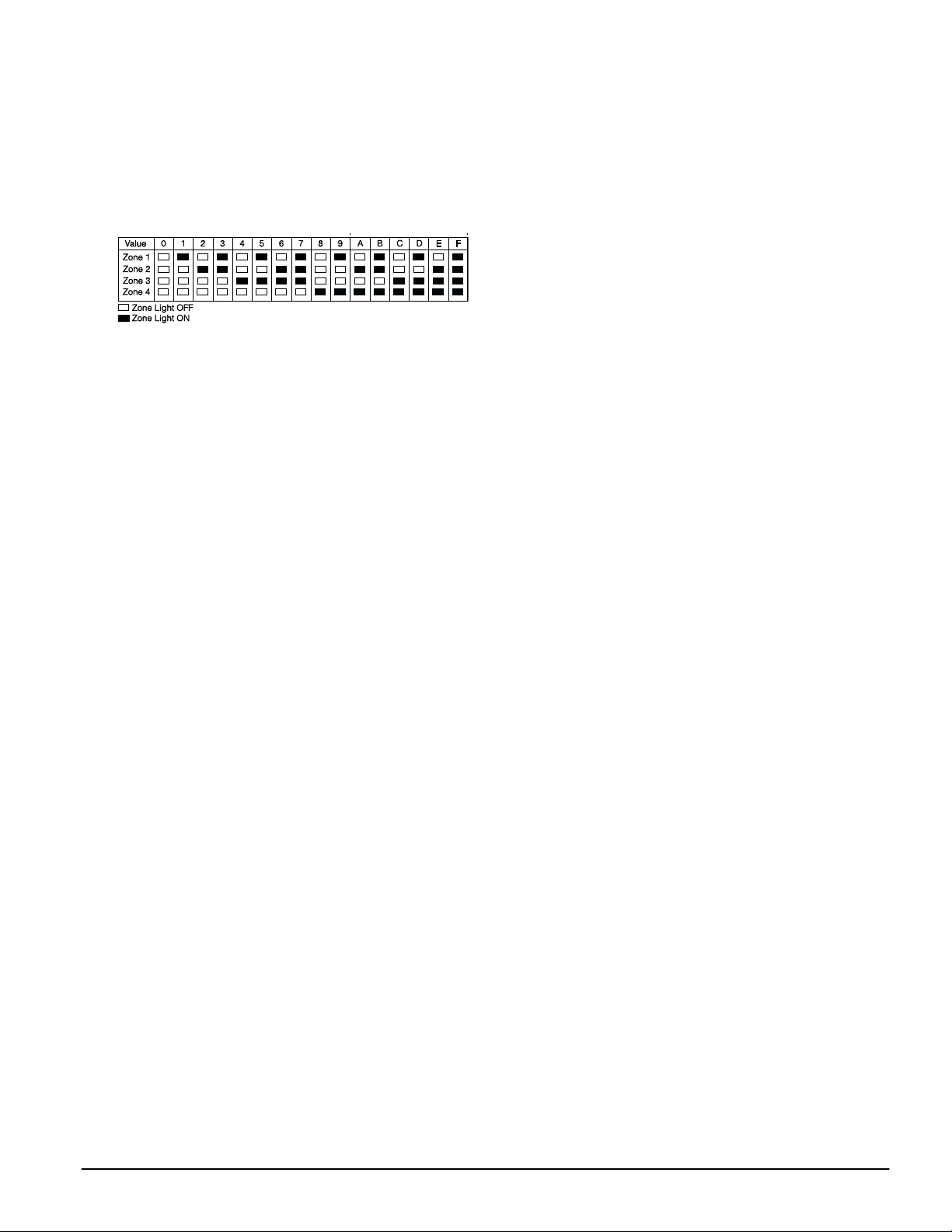
3.5 Viewing Programming
LED and LCD5501Z Keypads
Any programming section can be viewed from an LED or
LCD5501Z keypad. When a programming section is
entered, the keypad will immediately display the first
digit of information programmed in that section.
The keypad displays the information using a binary format, according to the following chart:
See Hex data
entry instructions
Press any of the Emergency keys (Fire, Auxiliary or Panic)
to advance to the next digit.
When all the digits in a section have been viewed, the
panel will exit the section: the Ready light will turn OFF,
and the Armed light will turn ON, waiting for the next
three-digit programming section number to be entered.
Press the [#] key to exit the section
LCD Keypad
When a programming section is entered, the keypad will
immediately display all the information programmed in
that section. Use the arrow keys (< >) to scroll through the
data being displayed. To exit the section, scroll past the
end of the data displayed, or press the [#] key.
12

Section 4: Keypad Commands
Use any system keypad to enter commands, or to program the PC5020 security system. The LED keypad uses function and
zone indicator lights to represent alarm functions and status. The LCD keypad provides a written description on the liquid
crystal display and uses function indicator lights to communicate alarm status to the user.
The PC5020 User’ s Guide provides basic directions for arming and disarming the system, bypassing zones and performing user
functions from the keypads. The following sections provide additional details on these functions.
4.1 Arming and Disarming
Arming
The system cannot be armed unless the Ready light is on.
If the Ready light is not on, ensure all protected doors and
windows are secure and stop movement in areas covered
by motion detectors.
When the Ready light is on, enter a valid access code. As
each digit is pressed the keypad will beep. If an incorrect
code is entered, the keypad will emit a steady 2-second
beep to indicate that the code was not correct. If the code
is correct but the Ready light was not on, the panel will
beep six times rapidly followed by a long 2-second beep
to indicate the system was not ready.
When the correct code is entered and the system is ready,
the panel beeps six times rapidly, and the Armed light
turns on. The panel begins counting down the Exit Delay.
If the Audible Exit Delay option is enabled, the keypad
will beep every second until the Exit Delay expires. The
keypad will beep rapidly for the last 10 seconds of Exit
Delay to warn the user the system is about to arm.
Exit the premises through the designated entry/exit door
before the Exit Delay expires.
Users can restart the Exit Delay while it is counting down
by pressing the Away key. The system will not log the
user who re-started the Exit Delay, unless the Quick Arm-
ing Disabled/Function Keys Require Code option is
turned on (Section [015], option [4]).
Other methods of arming are available (see Section “[*]
[0] Quick Arm”, ’[*][9] Arming without Entry Delay’, and
section 4.4 ’Function Keys’).
NOTE: The PC5020 has a built-in feature called Audible Exit Fault (see Section 5.3 Basic Programming PWS
Sect 3 [001]-[004] for more information).
Stay and Away Arming
When a user arms the system, if any zones on the system
have been programmed as Stay/Away, the panel will
immediately turn on the Bypass light. The panel will then
monitor all zones programmed as Delay 1 and Delay 2. If
no delay type zone is violated by the end of the Exit Delay
(i.e., nobody leaves through the entry/exit door), the
panel will bypass all Stay/Away type zones. The panel is
now Stay armed. The Bypass light will remain on to
inform the home owner that the interior protection is
bypassed. This is a convenience for users that want to
arm the panel while at home. Using this method, users do
not have to bypass the interior zones manually.
Users can add the Stay/Away zones back into the system
at any time by entering [*] [1] (see section ’[*][1] Zone
Bypassing’), or by using the Away function button.
If a delay zone is violated during the Exit Delay (i.e.,
somebody leaves through the designated entry/exit
door), all zones will be active after the Exit Delay expires.
The panel is now Away armed. The Bypass light on the
keypad will be off.
Other methods of Stay and Away arming are available
(see section ’Function Keys’).
Using the Away Button While Stay Armed
If a partition is armed in Stay mode and a user wishes to
leave the premises without having to disarm and re-arm
the system, they may press the Away button. The system
will begin counting the standard Exit Delay, allowing the
user to leave without actually disarming. The panel will
log ’Armed in Away Mode’ upon completion of the Exit
Delay. This feature is useful for users with Wireless Keys
with Stay/Away buttons, and who wish to have their
panel armed at all times.
Using the Stay Button While Away Armed
Pressing the Stay key while a partition is Away armed
will begin the Exit Delay again. The panel will log
’Armed in Stay Mode’. This feature is useful for users
with wireless keys with Stay/Away buttons, and who
wish to have their panel armed at all times.
NOTE: If function keys require the entering of an
access code, a valid access code must be entered to
toggle between arming modes. The access code used
to perform this function will be logged with ’User Log
User XX’. Swinger shutdown will be reset if the Stay or
Away buttons are pressed while the system is armed.
Disarming
To disarm the panel, enter the premises through the designated entry/exit door. The keypad will emit a steady
beep to warn that you must disarm the system. During
the last 10 seconds of entry delay the panel will pulse the
keypad beeper on and off rapidly to warn that the entry
delay is about to expire.
Enter a valid access code at the keypad. If an error is
made, re-enter the code correctly. When a correct code is
entered the keypad will turn off the Armed light and stop
the keypad buzzer.
If an alarm occurred while the panel was armed the Memory light and the zones which caused the alarm will be
flashing. Press the [#] key to return the keypad to the
Ready state.
Event Buffer
The panel will store the last 256 events that have occurred
on the system. Each event will contain the time, date, partition and the event itself along with the zone number,
access code number or any other information pertaining
to the event.
If the Event Buffer Follows Swinger Shutdo wn feature is
enabled the event buffer will not store events after the
swinger shutdown level has been reached. This will prevent the panel from overwriting the entire buffer if a
problem exists (see Section 5.3 Basic Programming PWS
Sect 3 [377]. The event buffer can be viewed three differ-
ent ways. It can be viewed through an LCD keypad,
printed on-site using the PC5400 printer module, or it can
be uploaded through the DLS software.
Viewing the Event Buffer
The following is the procedure for viewing the event
buffer through the LCD keypad:
• Step 1 - Enter [*] [6] [Master Code]
• Step 2 - Select ‘View Event Buffer’
13

The keypad will display the event number, partition, time
and date of the event in question. Use the [*] key to toggle
between this information and the event itself. Use the
arrow keys (<>) to scroll through the events in the buffer.
When you have finished viewing the event buffer press
the [#] key to exit.
NOTE: When viewing events for partitions 3 to 8 on a
PKP-LCD v2.x and lower keypad, they will show as
being logged in the ’System Area’.
4.2 [*] Commands
[*][1] Zone Bypassing
Users can bypass individual zones using the [*][1] keypad
command. This command can be used if users want to
have access to an area while the partition is armed, or to
bypass a defective zone (bad contact, damaged wiring)
until service can be provided.
A bypassed zone will not cause an alarm. Instructions on
zone bypassing can be found in the PC5020 User’s Guide
(’Zone Bypassing’).
When the partition is disarmed, all zones bypassed using
[*] [1] will be unbypassed, except for 24-Hr zones.
If the Code Required for Bypass option is enabled, an
access code will be required to enter the Bypass mode.
Only access codes with the Bypass attribute enabled will
be able to bypass zones (see section ’[*] [5] Programming
Access Codes’).
These features are also available on the [*][1] zone bypassing menu:
• Bypass Recall: Press [99] while in the [*][1] menu to
recall the last set of bypassed zones.
• Clear Bypasses: Press [00] while in the [*][1] menu to
clear all bypassed zones.
• Bypass Groups: Users can program a group of zones
to be bypassed (bypass group). Each partition can have
a different bypass group. To program a bypass group,
in the [*][1] menu, select the zones to be bypassed.
Press [95] to save the group. To recall the group, press
[*][1] followed by [91].
If the Code Required for Bypass option is enabled, the
Master code or Supervisor codes must be used to
access this feature.
NOTE: If a 24-hr zone is bypassed, ensure that the zone
is restored or disabled before removing the bypass.
Code required for bypass. . . . . . . . . . . . . Section [015], Option [5]
[*][2] Trouble Display
The panel constantly monitors itself for several different
trouble conditions. If a trouble condition is present, the
Trouble light will be ON and the keypad will beep twice
every 10 seconds. The trouble beep can be silenced by
pressing any key on any keypad. If Bell Squawk on Trou-
ble is enabled (section [014], option[5]), the bell will
squawk every 10 seconds when a Trouble condition is
present.
NOTE: If there is an AC Trouble, the keypad will not
beep for a General System Trouble.
To view Trouble conditions from an LED or LCD5501Z
keypad:
1. Press [*] [2].
2. The keypad will flash the Trouble light. The zone indicator lights corresponding to the present Trouble conditions will be ON.
When using an LCD keypad, the Trouble conditions will
be listed on the display. Users can scroll through the list of
present Trouble conditions using the arrow (< >) keys.
NOTE: Troubles can be viewed while armed using the
LCD keypad, provided the keypad is version 2.0 or
later. Older keypads will incorrectly display ’Fire Trouble’. If using older LCD keypads, program section [013],
option [3] as OFF to ensure that Troubles are displayed
correctly.
The various Troubles are described below:
Light Trouble
1 Service Required: Press [1] to determine the specific Trouble. Lights 1 - 8 will light up to indicate the Trouble:
2 AC Failure: AC power is no longer being supplied to the control panel. The Trouble light will flash if an AC Failure is present, if the Trouble Light
3 Telephone Line Monitoring Trouble (TLM): There is a problem with the telephone line. If the system has a LINKS1000, or an alternate commu-
4 Failure to Communicate (FTC): The communicator failed to communicate with any of the programmed telephone numbers (see section 5.6
5 Zone Fault (including Fire Zone): A zone on the system is experiencing trouble, meaning that a zone could not provide an alarm to the panel if
• Light [1] Low Battery: Main panel backup battery charge is low (below 11.5 volts under load).Trouble is restored when the battery
charges over 12.5 volts.
• Light [2] Bell Circuit Trouble: The bell circuit is open (see section ’Terminal Descriptions’).
• Light [3] General System Trouble: One or more of the following Troubles has occurred: the PC5204 power supply module has an AUX
failure, PC5204 Output #1 Trouble, Camera Trouble, Home Automation Trouble on the Escort5580(TC), or a printer connected to the
PC5400 printer module has a fault and is off-line. Users can view specific conditions in the event buffer.
• Light [4] General System Tamper: Tamper has been detected in a module.
• Light [5] General System Supervisory: The panel has lost communication with a module connected to the Keybus (See section 2.8
‘Confirming Module Supervision‘). The event buffer will log the event.
• Light [6] RF Jam: Please refer to the PC5132 Installation Manual for more information.
• Light [7] PC5204 Low Battery: The PC5204 module has a low backup battery.
• Light [8] PC5204 AC Failure: The PC5204 module has lost AC power.
NOTE: If you remove and then restore power to the main panel in order to service any PC5204 module, or any module being powered by a PC5204, you must also remove and then restore power to the PC5204 and any connected modules. This ensures that any
Troubles present on the module are correctly logged and/or annunciated.
Flashes if AC Fails option is programmed (section [016], option [2]). This trouble will not be displayed if the AC Trouble Displayed option is disabled (section [016], option [1]).
nicator, this trouble can be reported to the central station by programming reporting codes in sections [345] and [346].
‘Communicator Programming’).
required to do so (e.g., a fire zone is open, or there is a short on a DEOL zone, or a supervisory fault on a wireless zone). When a zone fault occurs,
the keypad(s) on the system will start to beep. Press [5] while in Trouble mode to view the affected zones.
NOTE: A Fire zone trouble will be generated and displayed in the armed state.
14

Keypad Commands: 4.2 [*] Commands
Light Trouble
6 Zone Tamper: A zone configured for double end of line resistor supervision has a tamper condition, or the tamper switch is open on a wireless
7 Device Low Battery: A wireless device has a low battery condition. Press [7] one, two, or three times to view which devices are experiencing bat-
8 Loss of System Time: When the panel is powered up, the internal clock needs to be set to the correct time. This trouble is cleared when an
device. When a tamper condition occurs, the keypad(s) will start to beep (if the system is armed, an alarm will occur). Press [6] while in Trouble
mode to view the affected zones. If a zone is tampered or faulted, it must be fully restored to clear the trouble.
tery failure. An LED keypad will indicate battery failure using zone lights. The following will occur:
Keypad beeps: Keypad displays:
Press [7] 1) Zones with low batteries (LED keypad - zone lights 1 to 32)
Press [7] again 2) Handheld keypads with low batteries (LED keypad - zone lights 1 to 4)
Press [7] again 3) Wireless keys with low batteries (LED keypad - zone lights 1 to 16)
attempt is made to reset the clock. This is set in ‘[*][6] User Functions’ Programming on page 16.
[*] [3] Alarm Memory
The memory light will be on if any alarm occurred during
the last armed period or if an alarm occurred while the
panel was disarmed (24-hr zones). Instructions on viewing alarms in memory are located in the PC5020 User’s
Guide (’Disarming the System’).
[*] [4] Door Chime On/Off
If enabled the keypad will beep 6 times rapidly when a
zone is tripped and restored. The panel will only do this
for zones with the Door Chime attribute enabled and if
the door chime feature is enabled (see Section 5.4 Advanced
Programming [101]-[164]).
[*] [5] Programming Access Codes
All access codes can arm and disarm any partition they
are enabled for, and can activate the PGM outputs using
the [*][7] commands (see section ’[*] [7] Command Output Functions’).
For instructions on programming access codes, see the
PC5020 User’s Guide (‘Programming Access Codes’).
The available access codes are as follows:
General Access Codes - Access Codes [01] to [32]
Each access code can be used to arm and disarm the
assigned partitions. Additional access code attributes are
also programmable to determine what abilities the code
will have.
You can program partition assignments and access code
attributes by following the instructions in this section.
Duress Codes - Access Codes [33] and [34]
When a Duress Code is used to perform any function the
panel will send a Duress reporting code to the central station (see Section 5.3 Basic Programming [001]-[004] and Sec-
tion 5.6 Communicator Programming ).
Supervisor Codes - Access Codes [41] and [42]
Supervisor Codes can program additional access codes.
By default, Supervisor codes have the same partition and
attribute programming as the Master code. You can
change the partition and attribute programming for these
codes by following the instructions in this section.
System Master Code - Access Code [40]
By default the System Master Code is enabled to operate
on all partitions, and can perform any keypad function.
This code can be used to program all access codes, including the Supervisor Codes and Duress Codes.
If the Master Code Not Changea ble option is enabled the
System Master Code can only be changed using Installer
Programming.
Maintenance Code
The maintenance code can only be used to arm and disarm the system. It cannot be used to bypass zones, to
access the Escort5580(TC), or to cancel or postpone automatic arming. The code can only be programmed in
Installer Programming.
Programming Partition Assignments and Access
Code Attributes
You can enable or disable each access code to work on
each partition. Additional access code attributes are also
programmable. Attributes determine what abilities the
code will have.
By default, each code has the attributes of the code used
to program it. For example, if you use the Master Code to
program other access codes, the new codes will have the
same attributes as the Master Code. You can change the
partition and attribute programming by following the
instructions described below.
You cannot change Master Code partition or attribute
programming. The Master Code has all partitions and all
attributes turned on, except for the Bell Squawk on Arming/Disarming attribute.
To program which partition(s) each code will work on:
1. Enter [*][5][Master Code][8] to enter partition programming.
2. Enter the 2-digit number of the access code you want to
edit.
3. Enter the partition number (1-8) to toggle it on or off.
NOTE: Partition programming is NOT supported at the
following keypads: PC5508(Z), PC5516(Z), PC5532(Z)
versions v2.00 and lower; LCD5500(Z) version 2.x and
lower; LCD5501Z version 1.x and lower.
To program each attribute:
1. Enter [*][5][Master Code][9] to enter the attribute programming mode.
2. Enter the 2-digit number of the access code you want to
edit.
3. Enter the attribute number to toggle it on or off.
The programmable attributes are as follows:
• Attributes 1-2: For Future Use.
• Attribute 3: Zone Bypass enabled.
This attribute allows the user to bypass zones.
• Attribute 4: Escort5580(TC) Remote Access
This attribute allows the user to access the security system via the Escort, if installed.
• Attribute 5: Downlook Remote Trigger to Telephone
Number 1. For use with the Escort5580(TC) and the
PC5108L/DLM-4L (see the PC5108L Installation Manual
for details).
• Attribute 6: Downlook Remote Trigger to Telephone
Number 2. For use with the Escort5580(TC) and the
PC5108L/DLM-4L (see the PC5108L Installation Manual
for details).
• Attribute 7: Bell Squawk on Arming/Disarming. When
this attribute is turned on, the bell will squawk when the
access code is entered to arm or disarm the system. For
example, you can use the arm/disarm bell squawk
attribute to have wireless key access codes squawk the
bell, while other codes are silent. To do this, enable
attribute [7] on all access codes associated with wireless
keys.
15
 Loading...