

DSC Power832PC5010 CP-01, Power832, PC5010 CP-01 Installation Manual

IMPORTANT
This manual contains information on limitations regarding product use and function and information on the
limitations as to liability of the manufacturer. The entire manual should be carefully read.
Now classified in accordance with ANSI/SIA CP-01-2000 (SIA-FAR)
Installation Manual
PC5010 CP-01
WWW.DIYALARMFORUM.COM
PC5010 CP-01 Version 3.2
DLS2002 and higher

WWW.DIYALARMFORUM.COM

New Features
PC5200 Support
PC5936 Support
SIA FAR
No Activity Arming
(by Partition)
Programmable
Auto-arm Pre-Alert
Timer
Periodic Test
Transmission
Exception
Cross Zoning
True Automatic
Contact ID
The PC5010 CP-01 v3.1 and higher supports the new PC5200 Power Supply module. See PC5200 Power Supply
Output Module, Pg 2.
The PC5010 CP-01 v3.1 and higher supports the PC5936 15-station audio matrix module. See PC5936 Audio Interface Module, Pg 3.
SIA False Alarm Reduction has been incorporated in this version. See the Quick Reference Chart SIA-FAR on the following page.
This feature enables the system (or partition) to arm if there is no zone activity for a programmed time period. See
sections [191]-[192] - No-Activity Timer (Partition 1-2).
The Auto- arm Pre-alert Time is now programmable. The default value for this timer has been extended to 5 minutes.
See Section [199] - Auto-arming Pre-Alert Time, Pg 30.
With this feature enabled, the panel will not send a test transmission if there has been any transmission received by
the receiver within the programmed time. See Section [018] - Sixth System Option Codes, Option 1, Pg 27.
This feature requires two or more trips on a zone(s) specified as “cross zones” within a specified time before starting
an alarm sequence. The Cross Zone option is programmable by zone via Attribute 9. See Section [018], Sixth System Option Codes,Option 6, Pg 28.
When selecting Automatic Contact ID for reporting, the reporting code will represent how a zone is defined according
to the SIA specification for Contact ID. If Automatic Contact ID is enabled, see Appendix A for reporting codes that
will be used for each zone type.
Keypad Buzzer
New Zone Types
Waterflow Silence
Inhibit Option
Verbal Door Chime
and Verbal Alarm
Support
Loop Response
T-Link
When enabled and the system or Partition is in alarm, all assigned keypad buzzers will follow the bell output. When
disabled, the keypad buzzers will only sound for buzzer type alarms. This option is off at default. See Section [018] Sixth System Option Codes, Option 5, Pg 28.
See Sections [001]-[002] - Zone Definitions, Pg 21.
Zone Type 27 - Delayed 24 Hour Waterflow Zone
Zone Type 28 - Instant 24 Hour Waterflow Zone
Zone Type 29 - Auto Verified Fire Zone
Zone Type 30 - Fire Supervisory Zone
Zone Type 31 - Day Zone
This option affects the Instant Waterflow Zone and the Delay Waterflow Zone.
This option does NOT allow the user to silence alarms, manually, automatically, or by a system reset until all waterflow
zones are returned to their restored state. See Section [018] - Sixth System Option Codes, Option 4, Pg 28.
This feature enables the Door Chime to verbally annunciate the Zone that has been violated instead of a series of
beeps. See Section [018] - Sixth System Option Codes, Option 2&3, Pg 33. This feature is only available when using
the ESCORT5580 v3.0, and the PC5936 v1.0. Refer to the Escort5580 v3.0 and PC5936 v1.0 Installation Manuals
for further information.
The PC5010 CP-01 v3.1 and higher can configure any or all onboard zones for 36 ms Loop Response (see Section
[030] - Fast Loop Response, Pg 29).
The PC5010 CP-01 v3.2 supports the T-Link TCP/IP Network Communicator.
WWW.DIYALARMFORUM.COM
ii

PC5010 CP-01 Installer Programming Quick Reference Chart SIA False Alarm Reduction
Minimum requirement system for SIA-FAR Installations :
• 1 PC5010 CP-01 Control Panel
• 2 Local Annunciation Devices
The local annunciation devices may be any combination of the following keypads.
• LCD5500Z/LCD5520Z LCD5501Z
• PKP-LCD PKP-ICN
The following optional subassembly modules also bear the SIA FAR classification
and may be used if desired:
PC5108 Zone Expander Module
Compatible initiating devices: Bravo200 series, 300 series, 400 series, 500 series,
600 series, AC-100, Encore300 series, Force200 series, 210 series, MN240.
PC5208 Low Current PGM Output Module
The following optional accessory modules also bear the SIA FAR classification and
may be used if desired.
PC5204 Auxiliary Power Supply with PGM output ports
Escort5580/Escort5580TC
PC5400 Printer Module
Section Number Installation
005 5.3 System Times: Access to Entry Delays and Exit Delay for each partition and Bell Time Out for the system.
009 – 011 5.3 Programmable Outputs: Access to PGM Output programming for the main board, PC5208 and PC5204 modules. Output
014, Option 6 5.3 Audible Exit Beeps: Enables beeps from the keypad for the duration of Exit Delay.
018, Option 6 5.3 Cross Zoning: This option enables Cross Zoning for the entire system. Individual zones can be enabled for Cross zoning
018, Option 7 5.3 Exit Delay Restart: Enables the Exit Delay Restart feature.
101 – 132 5.4 Zone Attributes: Access to zone attributes, such as, Audible Bell, Swinger Shutdown, Transmission Delay, and Cross Zone.
176 5.4 Cross Zone Timer: Access to the programmable Cross Zone timer.
304 5.6 Call Waiting Cancel Dialing String: Access to the Dialing sequence used to disable Call Waiting.
328, 6th Entry
328, 7th Entry
328, 8th Entry
348, 1st and 2nd Entries
377, 1st Entry
377, 4th Entry
377, 11th Entry
382, Option 2 5.6 Alarm Comms. During Walk Test: Enables Communication of zone alarms while installer Walk Test is active.
382, Option 3 5.6 Communications Cancelled Message: Enables the “Communications Cancelled” message display on all keypads.
382, Option 4 5.6 Call Waiting Cancel: Enables the use of the Call Waiting Cancel string in programmed in Section 304.
901 5.11 Installer Walk Test Mode: Enable/Disable Installer Walk Test mode. This mode can be used to test each zone on the sys-
[*][5] Master Code
33rd and 34th Entries
[*][6] Master Code
Option 4
Manual Section
Attributes in Section in Sections 501 – 514. Partition Assignments in Section 551 – 532.
via Zone Attributes in Sections 101 – 132. Default = OFF
5.6 Cross Zone Reporting Code: Access to the reporting code for Cross Zone Alarm.
5.6 Burglary not Verified Reporting Code: Access to the reporting code for Burglary Not Verified.
5.6 Alarm Cancelled Reporting Code: Access to the reporting code for Alarm Cancelled.
5.6 Walk Test End and Begin Reporting Codes: Access to the reporting codes for Walk Test Begin and Walk Test End.
5.6 Swinger Shutdown for Alarms: Access to the Swinger Shutdown limit for zone alarms.
5.6 Communications Delay: Access to the programmable delay before communicating alarms.
5.6 Communications Cancel Window: Access to the programmable Communications Cancel window.
tem for proper functionality.
4.1 Duress Code: Do not derive code from an existing Master/User code (eg., Master Code is 1234, the duress code should
not be 1233 or 1235.
4.3 System Test: The system activates all keypad sounders, bells or sirens for 2 seconds and all keypad lights turn on. Refer
to the User Manual (part no. 29005909).
Description
Caution
• For SIA FAR installations, only use modules / devices that are listed
on this page.
• Fire Alarm Verification feature (Auto Verified Fire zone) is not supported on 2-wire smoke detectors zones. This feature may be
enabled for 4-wire smoke detectors only.
• Call Waiting Cancel (Section 382 Option 4) feature on a non-Call
Waiting line will prevent successful communication to the central
station.
• All smoke detectors on the system must be tested annually by conducting the Installer Walk Test. Prior to exiting the walk test mode,
a sensor reset must be conducted on the system, [*][7][2] to reset
all latching 4-wire smoke detectors. Please refer to the smoke
detector installation instructions on how to correctly test the detectors.
WWW.DIYALARMFORUM.COM
Notes
• Programming at installation may be subordinate to other UL requirements for the intended application.
• Cross zones have the ability to individually protect the intended area
(e.g., motion detectors, which overlap).
• Cross zoning is not recommended for line security Installations nor is it to
be implemented on exit / entry zones.
• There is a communication delay of 30 seconds in this control panel. It can
be removed, or it can be increased up to 45 seconds at the option of the
end user by consulting with the Installer.
• Do not duplicate any reporting codes. This applies for all communication
formats other than SIA sending automatic programmed reporting codes.
• The control unit must be installed with a local sounding device and an
off-premise transmission for SIA communication format.
iii

Table of Contents
Section 1: Introduction 1
1.1 About the PC5010 CP-01 System ................................. 1
1.2 About the PC5010 CP-01 Manual Set .......................... 1
1.3 Main Panel Specifications ............................................. 1
1.4 Additional Devices ........................................................ 2
Section 2: Installation and Wiring 5
2.1 Installation Steps .......................................................... 5
2.2 Terminal Descriptions ................................................... 5
2.3 Wire Routing for Power & Non-Power Limited .............. 6
2.4 Keybus Operation and Wiring ....................................... 6
2.5 Current Ratings - Modules & Accessories ...................... 6
2.6 Assigning Zones to Zone Expanders .............................. 7
2.7 Keypad Assignment ...................................................... 7
2.8 Confirming Module Supervision ................................... 8
2.9 Removing Modules ....................................................... 8
2.10 Zone Wiring ................................................................. 8
2.11 Keypad Zones ............................................................. 10
Section 3: How to Program 11
3.1 How to Enter Installer Programming ........................... 11
3.2 Programming Decimal Data ........................................ 11
3.3 Programming Hexadecimal Data ................................. 11
3.4 Programming Toggle Options ..................................... 11
3.5 Viewing Programming ................................................ 12
Section 4: Keypad Commands 13
4.1 Arming and Disarming ................................................13
4.2 [✱] Commands ...........................................................14
4.3 Function Keys .............................................................17
4.4 Global and Partition Keypad Operation .......................18
4.5 Features Available for the LCD5500Z/LCD5520Z ......... 18
Section 5: Programming Sections 19
5.1 For the Record ............................................................20
5.2 Keypad Programming ..................................................20
5.3 Basic Programming ......................................................20
5.4 Advanced Programming .............................................29
5.5 Partition & Zone Programming.....................................30
5.6 Communicator Programming.......................................31
5.7 Downloading Options..................................................40
5.8 Programmable Output Programming ..........................41
5.9 International Programming .........................................42
5.10 Module Programming..................................................44
5.11 Special Installer Instructions ........................................44
Section 6: Listing Requirements 47
6.1 UL Listed Commercial and Residential Installations ......47
Appendix A: Reporting Codes 48
WWW.DIYALARMFORUM.COM
iv
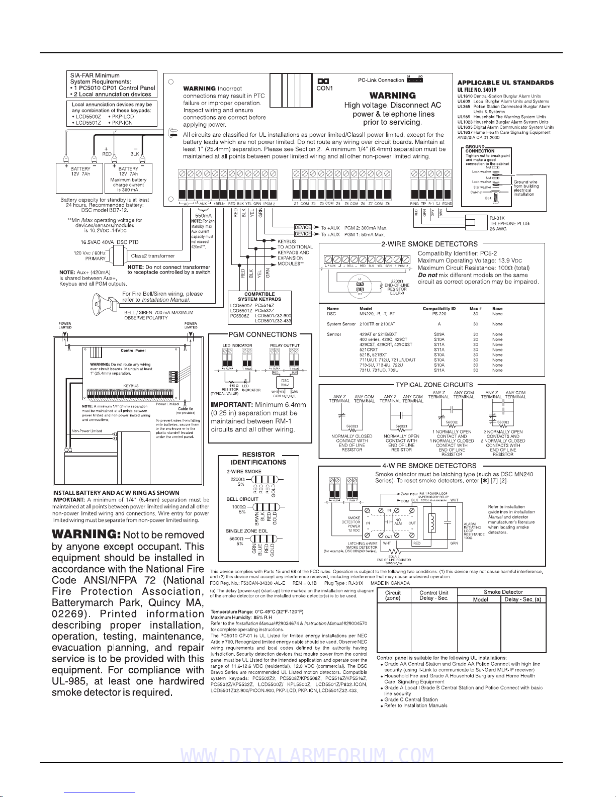
PC5010 CP-01 Wiring Diagram
NOTE: Remove CON1 when using PGM2
for 2-wire smoke
WWW.DIYALARMFORUM.COM
v

Section 1: Introduction
1.1 About the PC5010 CP-01 System
The PC5010 CP-01 is a high end security system. It supports up to 32 zones, 2 separate partitions, and 32 users.
The user interface is simple and easy to use. The
LCD5500Z/LCD5520Z keypad guides users through
their available options with easy-to-understand prompts.
The status of the PC5010 CP-01 system can be monitored
over telephone lines, or using an alternative communicating device, including LINKS1000, LINKS2X50,
LINKS3000, Skyroute™ and DVACS*.
The PC5010 CP-01 main board comes with 2 programmable outputs, and you can add up to 12 more using PC5204
and PC5208 modules. You can program the outputs to
control things such as doorstrikes and lights, using 25 different output options. See ‘Programmable Outputs’ in
Section 5.
You can program the PC5010 CP-01 using any system
keypad, or using DLS2002 downloading software and a
computer. See ‘How to Program’ on page 10.
Review the complete PC5010 CP-01 manual set before
installing the PC5010 CP-01 security system.
1.2 About the PC5010 CP-01 Manual Set
Installer Manuals
Read the entire manual carefully before beginning your
installation.
This manual describes:
• An overview of the system (Section 1: ’Introduction’)
• How to install and wire the system and its modules
(Section 2: ’Installation and Wiring’)
• How to program the system (Section 3: ’How to Program’)
• An introduction to the user interface and keypad operation (Section 4: ’Keypad Commands’)
• An overview of the main system programming sections (
Section 5
Be sure to record all your system programming in the
gramming Worksheets
gramming Worksheets
gramming Worksheetsgramming Worksheets
If you will be adding modules to your PC5010 CP-01 system, read the
module.
User’s Guide
One User’s Guide comes with the PC5010 CP-01 system.
User’s Guide
User’s Guide
The
User’s GuideUser’s Guide
end-users. Installers should also review this manual, in
order to properly instruct the end-users once the installation is complete.
: ’Programming Sections’).
.
Installation Instructions
Installation Instructions
Installation InstructionsInstallation Instructions
provides easy to follow instructions for
that come with each
1.3 Main Panel Specifications
Flexible Zone Configuration:
• 8 fully programmable zones
• 39 access codes: 32 user, 1 system master, 2 supervisor
codes, 2 duress, 1 maintenance and 1 installer code
• Expandable to 32 zones
• Keypads with zone inputs available (PC5508Z,
PC5516Z, PC5532Z, LCD5500Z/LCD5520Z, and
LCD5501Z)
• Hardwired expansion available using the PC5108 8zone expansion module, the PC5100 addressable 32
zone expansion module and the PC5700/5720 fire
module
• Wireless expansion available using the PC5132 wireless 32 zone expansion module (433 or 900MHz, fully
supervised)
Pro-
Pro-
Pro-Pro-
• Normally closed, Single EOL, or Double EOL zone
supervision
• 34 zone types, 8 programmable zone options
• Up to 2 partitions
Audible Alarm Output:
• 700mA supervised bell output (current limit 3 Amps),
DC
12 V
• Steady or pulsed output
EEPROM Memory:
• Will not lose programming or system status on complete AC and battery failure
Programmable Outputs:
• Up to 14 programmable outputs 21 programmable
options
• One low current (50mA) PGM output on main panel
(PGM1)
• One high current (300mA) PGM output with 2-wire
smoke detector capability on main panel (PGM 2)
• Eight additional low current (50mA) PGM outputs available using the PC5208 module
• Four high current (1 Amp) PGM outputs available using
the PC5204 module (1 PC5204 output, fully supervised
for siren output)
Powerful 1.5 Amp Regulated Power Supply:
• 550 mA auxiliary supply, 12 V
• Positive temperature coefficient (PTC) components
replace fuses
• Supervision for loss of AC power, low battery
• Internal clock locked to AC power frequency
NOTE:
Power Requirements:
Remote Keypad Specifications:
For 24-hr standby, maximum Aux capacity is 420mA.
• Transformer = 16.0 V
connected
• Battery = (2) 12V 7Ah (min.) rechargeable sealed lead
acid or (1) 12 volt 4Ah battery (for Burglary applications
only)
• PC5010 CP-01 current draw: 65mA
• Various keypads are available:
- PC5508Z 8 Zone LED keypad
- PC5516Z 16 Zone LED keypad
- PC5532Z 32 Zone LED keypad
- LCD5500Z/LCD5520Z Liquid Crystal Display keypad
- LCD5501Z LCD-style keypad
- LCD5501Z32-900/LCD5501Z32-433 keypad/receiver
• ’Z’ version keypads have one zone input
• Each keypad has 5 fully programmable function keys
• Connect up to 8 keypads
• Four wire (Quad) connection to Keybus
• Built in piezoelectric buzzer
DC
AC
, 40VA (min) permanently
*DVACS is a registered trademark of Electro Arts Limited.
WWW.DIYALARMFORUM.COM
1

Digital Communicator Specifications:
• Supports all major formats including SIA, Contact ID,
and Residential Dial
• Split reporting of selected transmissions to each telephone number
• 3 programmable telephone numbers
• 1 system account number, plus 2 partition account
numbers
• Supports LINKS1000, GSM1000 cellular communication, Links 2X50 long range alarm transmitter and Skyroute™ Cellemetry communication transceiver
• DTMF and pulse dialing
•DPDT line seizure
• Anti-jam detection
• Event-initiated personal paging
• T-Link communications via PC-Link (see T-Link Installation Manual part no. 29001007)
System Supervision Features
The PC5010 CP-01 continuously monitors a number of
possible Trouble conditions including:
•AC power failure
•Trouble by zone
•Fire trouble
• Telephone line trouble
• Low battery condition
• Bell output trouble
• Loss of internal clock
• AUX power supply fault
• Tamper by zone
• Failure to communicate
• Module Fault (Supervisory or Tamper)
• Camera Troubles via DLM-4L
False Alarm Prevention Features
• Audible Exit Delay
• Audible Exit Fault
• Urgency on Entry Delay
• Quick Exit
•Swinger Shutdown
• Recent Closing Transmission
• Cross Zone Alarm
• Burglary-verified timer
• Double Hit Timer
• Communication Delay
• Rotating Keypress Buffer
Additional Features
• Automatic arming by partition at a specified time, each
day of the week
• Keypad-activated alarm output and communicator test
• Keypad lockout
• Audio capability using the PC5936 audio interface module; allows local intercom and central station 2-way listen-in
• All modules connect to the system via a four wire Keybus, up to 1000’/305m from the main panel
• Event buffer can be printed using PC5400 RS-232 serial
interface module
• Supports the Escort5580(TC) Voice Prompt Module,
with automation and lighting control
• 256-event buffer, time and date stamped
• Uploading/downloading capability
• Daylight Savings Time option
• Downlook support (DLM-4L v1.0 and PC5108L)
1.4 Additional Devices
In addition to the information below, see the back cover for
a DSC Module Compatibility table.
Keypads
A maximum of 8 keypads can be connected to the control
panel. You can connect any combination of the following
listed. Different keypads (with function keys) can be used
for different size systems: 8 zone, 16 zone, 32 zone.
• PC5508Z: 8 zone LED keypad, with one zone input
• PC5516Z: 16 zone LED keypad, with one zone input
• PC5532Z: 32 zone LED keypad, with one zone input
• LCD5500Z/LCD5520Z: LCD keypad, with one zone input
• LCD5501Z: LCD-style keypad, with one zone input
• LCD5501Z32-433: keypad/receiver
PC5100 2-Wire Addressable Device Interface Module
The PC5100 module is used to connect 2-wire addressable
devices to the system. Up to 32 2-wire addressable devices
can be added to the system.
PC5108 Eight Zone Expander Module
Eight zone expander module can be used to increase the
number of zones on the system. Up to 7 modules can be
connected to increase the system zones to a maximum of
32
(see the PC5108 Installation Instructions Sheet).
NOTE:
ules and use up two supervisory slots.
NOTE:
PC5108 v2.0 and higher modules on the same system.
PC5132 Wireless Receiver Module
The PC5132 wireless receiver module can be used to connect up to 32 fully supervised wireless devices
PC5132 Installation Manual for details.)
PC5200 Power Supply Output Module
The PC5200 can provide up to 1 Amp of additional power
for modules or devices connected to the control panel. Up
to 4 modules can be connected to the system. Each module
requires a 16.5 volt AC 40 VA transformer and 4Ah battery
(see PC5200 Installation Instructions for details).
PC5204 Power Supply Output Module
The PC5204 can provide up to 1 Amp of additional power
for modules or devices connected to the control panel. The
module requires a 16.5 volt AC 40 VA transformer and 4
Ah battery. In addition, the module provides 4 programmable high current voltage outputs.
tion Instructions for details).
PC5208 Eight Low Current Output Module
Adds 8 programmable low current outputs (50mA) to the
control
details).
Escort5580(TC) Module
This Escort5580(TC) module will turn any tone telephone
into a fully functional keypad. The module also includes a
built-in interface to control up to 32 line carrier type
devices for lighting and temperature control
Escort5580(TC) Installation Manual for details.)
PC5108 v1.0 and lower modules enroll as two mod-
Do not mix PC5108 v1.x and lower modules with
(See PC5204 Installa-
(see the PC5208 Installation Instructions for
(see the
(see the
WWW.DIYALARMFORUM.COM
2

Introduction:
1.4 Additional Devices
PC5936 Audio Interface Module
The PC5936 audio interface module provides paging,
intercom, baby listen-in and door answer to the PC5010
CP-01 control panel. The module has built-in two-way
voice capability for central station
(see the PC5936 Instal-
lation Manual for details).
Three additional devices are available:
• PC5921 PKP-ICM Intercom Audio Station can be used in
conjunction with the PC5936 Audio Interface Module
• PC5921 EXT Door Box Audio Station can be used in
conjunction with the PC5936 Audio Interface Module
• PC5921 EXT/R Door Box Audio Station can be used in
conjunction with the PC5936 Audio Interface Module.
The Door Box contains a relay so the normal door bell
can be used instead of the internal one generated by the
PC5936 Audio Interface Modules.
PC5400 Printer Module
This PC5400 printer module will allow the panel to print
out all events that occur on the system to any serial
printer. All events will be printed with the partition, time,
date and the event that occurred
(see PC5400 Installation
.
Manual for details).
LINKS1000 Cellular Communicator
The LINKS1000 Cellular Communicator provides an efficient, cost-effective method for adding cellular back-up.
The unit comes in its own cabinet with antenna and
requires a separate battery and transformer
(see
Links1000 Cellular Communicator in Section 5).
T-Link Local Area Network Communicator
The T-Link Local Area Network Communicator provides
an efficient method of communicating via a Local Area
Network (LAN). See the T-Link
more details.
Alternate Communicators
Refer to the associated
LINKS3000, & Skyroute™ programming details.
Downlook Support: PC5108L and DLM-4 v1.0L
The PC5108L will expand the control panel’s zone capability by adding eight fully programmable zone inputs.
The module will also act as an interface between the
DLM-4L v1.0 video transmission module and the PC5010
CP-01 control panel. The PC5108L is also an 8-camera
video switcher.
Installation Manual
Installation Manual
for LINKS2X50,
for
For more information on either module, see their respective Installation Manuals.
NOTE:
PC5108 v2.0 and higher modules on the same system.
PC5700 Fire Module
This is a zone expansion module with four general purpose zone inputs, two Class A supervisory waterflow
zone inputs, ground fault detection and dual-supervised
telephone line inputs.
PC5720 Fire Module
This is a zone expansion fire module that can be used for
ULC Listed non-residential fire applications. The PC5720
can also be used as an interface between the control panel
and either a serial printer or a DVACS communications
network.
NOTE:
expander modules and use two supervisory slots.
NOTE:
modules with PC5108 v2.0 and higher modules on the same
system.
Do not mix PC5108L v1.x and lower modules with
The PC5700 v1.x and PC5720 v1.x enroll as two
Do not mix PC5700 v1.x and PC5720 v1.x and lower
Cabinets
Several different cabinets are available for the PC5010 CP01 modules. They are as follows:
• PC4050C -
PC4050C - alternate main control cabinet (Household
PC4050C - PC4050C Fire & Burglary) for the PC5010 CP-01 main panel.
Dimensions 305mm x 376mm x 125mm / 12.0” x 14.8”
x 4.9” approximately.
• PC4050CAR
PC4050CAR - alternate main control cabinet (Commer-
PC4050CARPC4050CAR
cial Burglary) for the PC5010 CP-01 main panel.
Dimensions 305mm x 376mm x 125mm / 12.0” x 14.8”
.
x 4.9” approximately.
• PC4050CRAR
PC4050CRAR - alternate main control cabinet (Com-
PC4050CRARPC4050CRAR
mercial Burglary) for the PC5010 CP-01 main panel.
Dimensions 305mm x 376mm x 125mm / 12.0” x 14.8”
x 4.9” approximately.
•••• PC500C -
PC500C - alternate main control cabinet (Household
PC500C - PC500C Burglary). Dimensions 213mm x 235mm x 78mm / 8.4”
x 9.25” x 3” approximately.
• PC5002C -
PC5002C - cabinet to house the PC5204 power supply
PC5002C -PC5002C output module. Dimensions 213mm x 235mm x 78mm
/ 8.4” x 9.25” x 3” approximately.
• PC5003C -
PC5003C - main control cabinet for the PC5010 CP-01
PC5003C - PC5003C main panel. Dimensions 222mm x 298mm x 78mm /
11.3” x 11.7” x 3.0” approximately (Household Fire &
Burglary).
• PC5004C -
PC5004C - cabinet to house the Escort5580(TC) module
PC5004C -PC5004C and PC5400 Printer Module. Dimensions 229mm x
178mm x 65mm / 9” x 7” x 2.6” approximately.
• PC5001C
PC5001C - cabinet to house the PC5108 zone expander
PC5001C PC5001C
module and the PC5208 8 low current output module.
Dimensions 153mm x 122mm x 38mm / 6” x 4.8” x
1.5” approximately.
• PC5001CP -
PC5001CP - plastic cabinet to house the PC5108 zone
PC5001CP -PC5001CP expander module and the PC5208 8 low current output
module. Dimensions 146mm x 105mm x 25.5mm /
5.75” x 4.2” x 1” approximately.
•CMC-1
CMC-1 - alternate main control cabinet (Commercial
CMC-1CMC-1
Burglary) Dimensions 222mm x 298mm x 78mm / 11.3”
x 11.7” x 3.0” approximately.
•Multi-3
Multi-3 - cabinet to house the PC5936/PC5937 mod-
Multi-3Multi-3
ules. Dimensions 287mm x 298mm x 78mm / 11.3” x
11.7” x 3.0” approximately.
•HS-CAB100
HS-CAB100 - structured wiring cabinet for PC5010 CP-
HS-CAB100HS-CAB100
01 main panel. Dimensions 362mm x 229mm x 102mm
/ 14.25” x 9” x 4” with a wire raceway positioned on the
right side of the cabinet. The cover is 389mm x 254mm
/ 15.3” x 10”.
• HS-CAB1400
HS-CAB1400 - structured wiring cabinet for PC5010 CP-
HS-CAB1400HS-CAB1400
01 main panel. Dimensions are 362mm x 362mm x
102mm / 14.25” x 14.25” x 4” with a wire raceway in the
center of the cabinet. The cover is 389mm x 389mm /
15.3” x 15.3”.
• HS-CAB2800
HS-CAB2800 - structured wiring cabinet for PC5010
HS-CAB2800HS-CAB2800
CP-01 main panel. Dimensions 724mm x 362mm x
102mm / 28.5” x 14.25” x 4” with a wire raceway in the
center of the cabinet. The cover is 752mm x 387mm /
29.6” x 15.3”.
• HS-CAB4200
HS-CAB4200 - structured wiring cabinet for PC5010
HS-CAB4200HS-CAB4200
CP-01 main panel. Dimensions 1086mm x 362mm x
102mm / 42.75” x 14.25” x 4.0” with a wire raceway in
the center of the cabinet.
WWW.DIYALARMFORUM.COM
3

Backplates
There are two different backplates available for keypads
to mount an audio station next to a keypad:
PC55BP1 Backplate
Use this backplate when
mounting an audio station
next to a keypad. Dimensions 208mm x 115mm x
18mm / 8.2” x 4.5” x 0.25”
approximately.
PC55BP2 Backplate
Use this backplate when
mounting an audio station
next to a keypad. In addition the backplate will
allow you to mount a
PC5108 zone expander
module or the PC5208 8
low current output module. Dimensions 208mm x
115mm x 18mm / 8.2” x 4.5” x 0.7” approximately.
WWW.DIYALARMFORUM.COM
4

Section 2: Installation and Wiring
The following sections provide a complete description of how to wire and configure devices and zones.
2.1 Installation Steps
The following steps are provided to assist with the installation of the panel. It is suggested that you read over this
section briefly to get an overall understanding of the
order of installation. Once this is done carefully work
through each step. Working from this plan will help
reduce problems and reduce the overall installation time
required.
Step 1 Create a Layout
Draw a rough sketch of the building and include all alarm
detection devices, zone expanders, keypads and all other
modules that are required.
Step 2 Mounting the Panel
Locate the panel in a dry area, preferably located near an
unswitched AC power source and the incoming telephone line. Before attaching the cabinet to the wall be
sure to press the five circuit board mounting studs into
the cabinet from the back.
NOTE:
ing the battery.
Step 3 Wiring the Keybus (Section 2.4)
Wire the Keybus to each of the modules following the
guidelines provided.
Step 4 Assigning Zones to Zone Expanders
(Section 2.6)
If zone expander modules are being used the modules
must be configured so the panel knows which zones are
assigned to each expander. Follow the guideline provided
to assign zones to expanders.
Step 5 Zone Wiring (Section 2.10)
Power down the control panel and complete all zone wiring. Follow the guidelines provided in section 2.10 to connect zones using normally closed loops, single EOL
resistor, double EOL resistors, Fire zones and Keyswitch
Arming zones.
Step 6 Completing Wiring
Complete all other wiring including bells or sirens, telephone line connections, ground connections or any other
wiring necessary. Follow the guidelines provided in section 2.2 ‘Terminal Descriptions’.
Step 7 Power up the Control Panel
Once all zone wiring and Keybus wiring is complete,
power up the control panel.
NOTE:
connected.
Step 8 Keypad Assignment (Section 2.7)
Keypads must be assigned to different slots to be properly supervised. Follow the guideline provided in section
2.7 to assign keypads.
Step 9 Confirming Module Supervision
(Section 2.8)
By default, all modules are supervised upon installation.
Supervision is enabled at all times so that the panel can
indicate a Trouble if a module is removed from the system.
To confirm that each module is properly supervised, follow the guidelines provided in section 2.8.
Step 10 Programming the System (Sections 4 & 5)
Section 4.0 provides a complete description of how to program the panel. Section 5.0 contains complete descriptions
of the various programmable features, what options are
Complete all wiring before applying AC or connect-
The panel will not power up if only the battery is
available and how the options function. The
Worksheets
ing to program the system.
Step 11 Testing the System
Test the panel completely to ensure that all features and
functions are operating as programmed.
should be filled out completely before attempt-
2.2 Terminal Descriptions
AC Terminals
The panel requires a 16.5 volt, 40 VA transformer. Connect
the transformer to an unswitched AC source and connect
the transformer to these terminals.
NOTE:
ing is complete.
Battery Connection
The battery is used to provide backup power in the event
of an AC power failure and to provide additional current
when the panel demands exceed the power output of the
transformer, such as when the panel is in alarm.
NOTE:
complete.
Connect the RED battery lead to the positive of the battery, the BLACK battery lead to the negative.
Auxiliary Power Terminals - AUX+ and GND
These terminals provide up to 550mA of current at 12
VDC
tions) for devices requiring power. Connect the positive
side of any device requiring power to the AUX+ terminal,
the negative side to GND. The AUX output is protected; if
too much current is drawn from these terminals (wiring
short) the panel will temporarily shut off the output, until
the problem is corrected. NOTE: The maximum AUX
capacity for 24-hr standby is 420mA.
Bell Output Terminals - BELL+ and BELL-
These terminals provide up to 3 Amps of current at 12
V
tions) (with standby battery; 700 mA continuous) for powering bells, sirens, strobes or other warning type
equipment. Connect the positive side of any alarm warning device to BELL+, the negative side to BELL–. The BELL
output is protected; if too much current is drawn from
these terminals (wiring short) the BELL PTC will open.
The bell output is supervised. If no alarm warning device
is being used connect a 1K
BELL– to prevent the panel from displaying a Trouble condition (see section ’[*][2] Trouble Display’
used for this application must be UL Listed and have a
current consumption of 400mA or less (e.g. Wheelock
MT-12/24-R).
Do not connect the transformer until all other wir-
Do not connect the battery until all other wiring is
(rated 11.6-12.6 V
DC(rated 11.6-12.6 V
Programming
DC
for UL residential applica-
DC
for UL residential applica-
Ω
resistor across BELL+ and
).
For UL installations, when a
bell or siren is used for fire
signaling with a pulsed
cadence, it must be connected between the AUX+
and BELL- terminals. To
maintain bell circuit supervision, do not connect more
than one device to the BELLterminal. A fire bell or siren
WWW.DIYALARMFORUM.COM
5
Keybus Terminals - RED, BLK, YEL, GRN
The Keybus is used by the panel to communicate with
modules and by modules to communicate with the panel.
Each module has four Keybus terminals that must be connected to the four Keybus terminals on the panel. For
more information, see section ’Keybus Operation and
Wir ing’
.
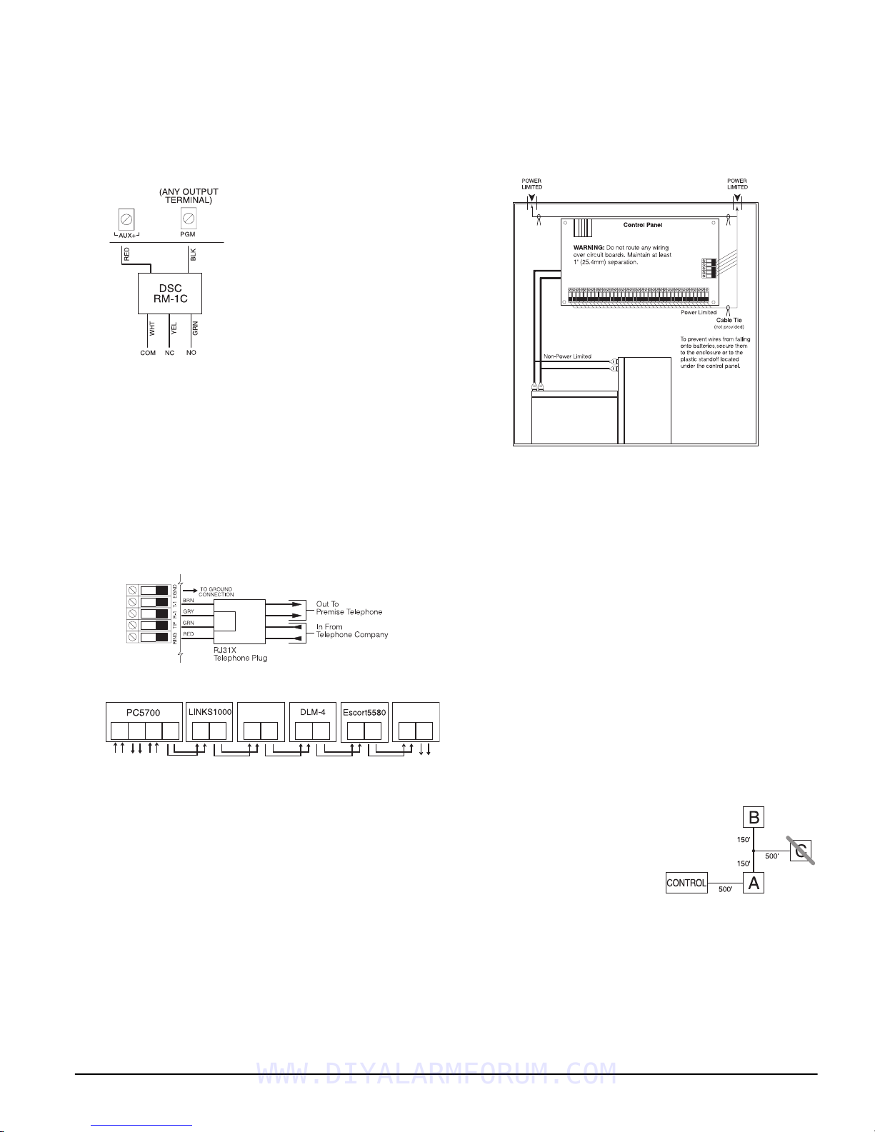
Programmable Outputs PGM1, PGM2
Each PGM output is designed so
that when activated by the panel,
the terminal will switch to ground
PGM1 can sink up to 50 mA of
current. These PGMs can be used
to activate LEDs or a small buzzer.
Connect the positive side of the
LED or buzzer to AUX+, the negative side to the PGM.
PGM2 is a high current output
(300mA) and operates similarly to
PGM1. If more than 300 mA of cur-
rent is required, a relay must be
used. PGM2 can be used for 2-wire smoke detectors with
Jumper CON1 removed, otherwise, CON1 must remain on
at all times (see section 2.10 ‘Zone Wiring‘).
Zone Input Terminals - Z1 to Z8
Each detection device must be connected to a zone on the
control panel. It is suggested that each zone have one
detection device however it is possible to wire multiple
detection devices to the same zone.
For zone wiring specifics, see section ’Zone Wiring’
.
Telephone Connection Terminals - TIP, RING, T-1, R-1
If a telephone line is required for central station communication or downloading, connect an RJ-31X jack in the
following manner:
Connect the PC5010 CP-01 and modules that use the telephone line(s) in the following order:
PC5936
T-1
TIP
T-1
RNG
R-1
TIP2
T-2
RNG2
R-2
To premise
Line 2 from
Telephone Company
TIP1
T-1
RNG1
Line 1 from
Telephones
Telephone Company
PC5010
TIP
RNG
R-1
TIP
T-1
R-1
RNG
T-1
TIP
T-1
RNG
R-1
TIP
RNG
R-1
For example, if you are installing a PC5010 CP-01 with a
LINKS1000/GSM1000 and a PC5936 intercom module,
connect the incoming line to the LINKS1000, then from
the LINKS1000 to the PC5010 CP-01, then from the
PC5010 CP-01 to the PC5936 audio module and then from
the PC5936 module to the house telephones.
NOTE:
Ensure that all plugs and jacks meet the dimension,
tolerance and metallic plating requirements of 47 C.F.R. Part
68, SubPart F. For proper operation there must be no other
telephone equipment connected between the control panel
and the telephone company facilities.
NOTE:
Do not connect the alarm panel communicator to
telephone lines intended for use with a FAX machine. These
lines may incorporate a voice filter which disconnects the
line if anything other than FAX signals are detected, resulting in incomplete transmissions.
2.3 Wire Routing for Power & Non-Power Limited
All wiring entry points are designated by the arrows. All
circuits are classified UL installation power limited except
for the battery leads which are not power limited.
A minimum ¼” (6.4mm) separation must be maintained
at all points between power limited and non-power limited wiring and connections.
Keybus
NOTE: A minimum 1/4" (6.4mm) separation
must be maintained at all points between
power limited and non-power limited wiring
and connections.
NOTE:
Wire entry for power limited wiring must be separated by a different entry access from non-power limited
wiring.
2.4 Keybus Operation and Wiring
The Keybus is used by the panel to communicate with all
modules connected and by the modules to talk to the
panel. The RED and BLK terminals are used to provide
power while YEL and GRN are clock and data.
NOTE:
The 4 Keybus terminals of the panel must be connected to the 4 Keybus terminals or wires of all modules.
The following conditions apply:
• Keybus should be run in minimum 22 gauge quad
(0.5mm), two pair twisted preferred
• the modules can be home-run to the panel, connected in
series or can be T-tapped
• any module can be connected anywhere along the Keybus; you do not need a separate Keybus wire run for
keypads, zone expanders etc.
R-1
• no module can be more than 1,000'/305m (in wire
length) from the panel
• shielded wire is not necessary unless wires are run in an
To premise
Telephones
Example of Keybus Wiring
area that may present excessive RF noise or interference
Module (A) is wired correctly as it is within 1,000'/
305m of the panel, in wire
distance. Module (B) is
wired correctly as it is
within 1,000'/305m of the
panel, in wire distance.
Module (C) is NOT wired
correctly as it is further than 1,000'/305m from the panel,
in wire distance.
2.5 Current Ratings - Modules & Accessories
In order for the PC5010 CP-01 system to operate properly,
the power output capabilities of the main control and
expansion devices must not be exceeded. Use the data
presented below to ensure that no part of the system is
overloaded and cannot function properly.
WWW.DIYALARMFORUM.COM
6
Installation and Wiring:
2.6 Assigning Zones to Zone Expanders
PC5010 CP-01 Device Ratings (@ 12 V
• LCD5500Z/LCD5520Z Keypad: 85 mA
• LCD5501Z Keypad: 45mA
• LCD5501Z32-433 Keypad/Receiver: 260mA (max.)
• PC5100 Addressable Device Interface Module: 40mA
• PC5508Z Keypad: 80 mA
• PC5516Z Keypad: 90 mA
• PC5532Z Keypad: 120 mA
• PC5108 Zone Module: 35 mA
• PC5108L Downlook Interface: 60 mA
• PC5132 Wireless Module: 125 mA
• PC5200 Output Module: 20 mA
• PC5204 Output Module: 20 mA
• PC5208 Output Module: 50 mA
• PC5320 Multiple Receiver Interface Module: 55mA
• Escort5580(TC) Module: 150 mA
• PC5400 Printer Module: 65 mA
• PC5700 Fire Module: 150 mA
• PC5904 Central Station Talk/Listen Module: 175mA
• PC5936 Audio Interface Module: 65 mA
• PC5937 Audio Port Expansion Module: 5mA
• PC5921 Intercom Audio Station: 20 mA
• PC5921 EXT Door Box Audio Station: 20 mA
• PC5921 EXT/R Door Box Audio Station: 35 mA
• DLM-4L v1.0: 180 mA
• T-Link module: 150mA
)
System Outputs (all 12 V
PC5010
CP-01
PC5200 VAUX: 1.0 A.
PC5204 VAUX: 1.0 A.
PC5208 VAUX: 250 mA.
PC5108 VAUX: 100 mA.
VAUX: 550 mA.
BELL: 700 mA.
Subtract the listed rating for each keypad, expansion module and accessory connected to VAUX or
Keybus. NOTE: The maximum AUX capacity
for 24-hr standby is 420mA.
Continuous Rating.
3.0 A.
Short Term. Available only with standby battery
connected.
Continuous Rating. Subtract for each device connected.
3.0 A.
Short Term. Available only with standby battery
connected.
Continuous Rating. Subtract for each device connected.
3.0 A.
Short Term. Available only with standby battery
connected.
Subtract for each device connected. Subtract the
total load on this terminal from the PC5010 CP01 VAUX/Keybus output.
Subtract for each device connected. Subtract the
total load on this terminal from the PC5010 CP01 VAUX/Keybus output.
DC
Other Devices
Read the manufacturer’s literature carefully to determine
the maximum current requirement (during activation or
alarm) and use this value for loading calculations. Do not
allow connected devices to exceed the system capabilities
during any possible operational mode.
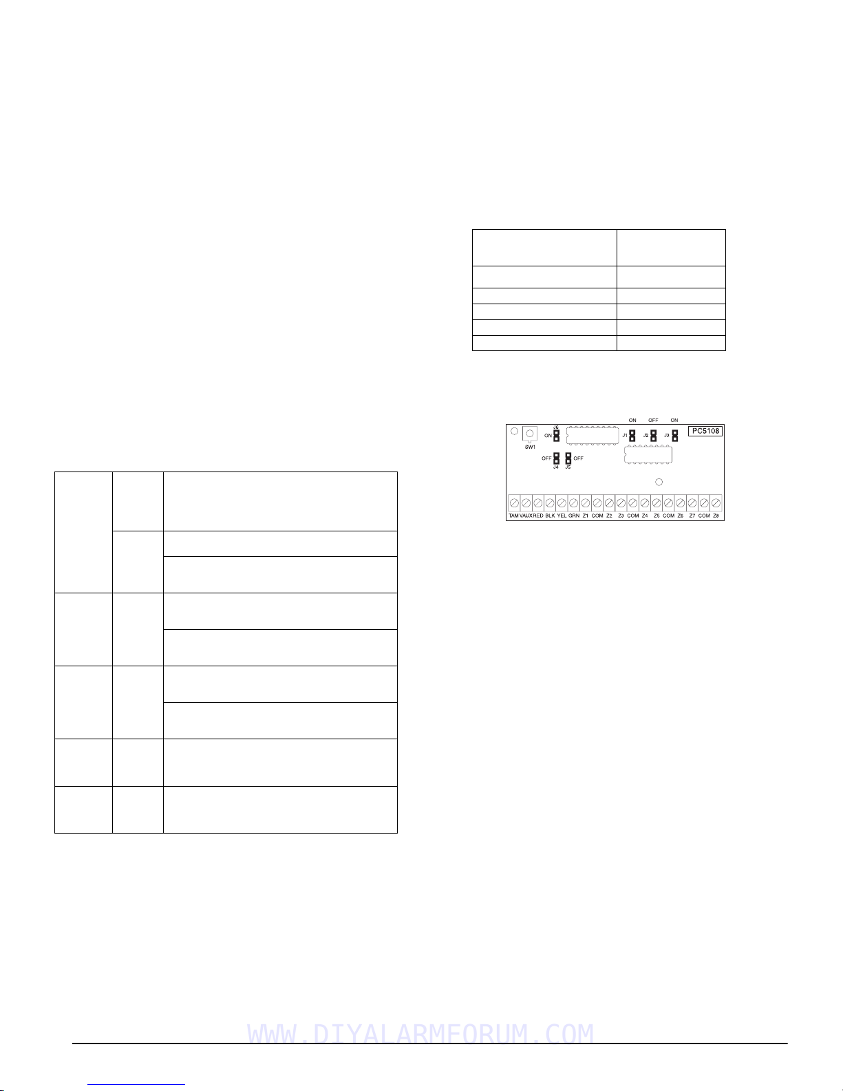
2.6 Assigning Zones to Zone Expanders
The main panel contains zones 1 to 8. Additional zone
expanders may be added to increase the number of zones
on the system. Each zone expander consists of one group
of 8 zones. Each module must be set to assign the specific
zones to the expander. To do this, set the jumpers located
on the expander to the proper settings (see chart below).
WWW.DIYALARMFORUM.COM
DC
)
NOTE:
PC5720 each enroll as two expander modules.
NOTE:
must set the jumpers so the panel can determine the correct
zone assignment.
NOTE:
simultaneously on the same PC5010 CP-01.
PC5108 v1.0 and lower, PC5108L, PC5700, and
Before a zone expander will work properly, you
It is not recommended to use PC5108 v1.x and v2.x
The following are the jumper settings for different zone
assignments for PC5108 v2.0 modules. If you need to
enroll PC5108 v1.0, PC5108L or PC5700 modules, refer to
the appropriate module
Installation Sheet
for the correct
jumper settings.
Module Jumpers
J1 J2 J3
ON ON ON Zones disabled
OFFONONZones 09 - 16
ON OFF ON Zones 17 - 24
OFF OFF ON Zones 25 - 32
System Zones
Assigned
The following is a diagram of the PC5108 zone expander
modules and where the jumper switches are located. Refer
to the
Installation Instructions
for the module for more
information.
NOTE:
assignment for the module.
Only jumpers J1, J2, and J3 determine the zone
2.7 Keypad Assignment
There are 8 available slots for keypads. LED and
LCD5501Z keypads by default are assigned to slot 1. The
LCD5500Z/LCD5520Z is assigned by default to slot 8.
Keypads can each be assigned to a different slot (1 to 8)
which offers two advantages. The panel can supervise the
keypad connection to indicate a Trouble condition if it is
removed. Also keypads can be assigned to operate a specific partition, or to operate as a global keypad.
How to Assign Keypads
NOTE:
All keypad assignment must be done at each keypad
on the system. When using LCD5500Z/LCD5520Z keypads,
one keypad must remain in slot 8. Do not assign more than
one keypad to the same slot.
NOTE:
To assign a keypad to a slot and select the partition
it will operate, enter the following:
1. Enter Installer Programming
2. Press [000] for Keypad Programming
3. Press [0] for Partition and Slot Assignment
4. Enter a two digit number to specify the partition and slot
assignment.
1st digit enter 0 for Global operation, or
enter 1-2 for partitions 1-2
2nd digit enter 1 to 8 for Slot Assignment
5. Press the [#] key twice to exit programming.
6. Continue this procedure at each keypad until all have
been assigned to the correct slot and partition.
7

How to Program Function Keys
Each of the 5 function keys on each keypad may be programmed for different operation.
1. Enter Installer Programming.
2. Press [000] for Keypad Programming.
3. Enter [1] to [5] to select function key to program.
4. Enter a 2-digit number for function key option - [00] to [30].
5. Continue from step 3 until all function keys are programmed.
6. Press [#] key twice to exit Installer Programming.
For a complete list of Function Key options, see section
’Function Keys’
.
2.8 Confirming Module Supervision
By default, all modules are supervised upon installation.
Supervision is enabled at all times so that the panel can
indicate a trouble if a module is removed from the system.
To check which modules are currently connected and
supervised:
1. Press [*] [8] [Installer Code] to enter Installer Programming.
2. Press [903] to display all modules.
3. The LCD keypad will allow you to scroll through the
modules.
NOTE:
LCD5500Z v2.x and lower keypads.
Keypad Light Module/Device Present
Module supervision will not display correctly at the
In LED keypads, zone lights will be turned on according
to what modules the panel has found on the system.
Refer to the following chart:
[1] Keypad 1
[2] Keypad 2
[3] Keypad 3
[4] Keypad 4
[5] Keypad 5
[6] Keypad 6
[7] Keypad 7
[8] Keypad 8
[9] Zones 9 to 16
[10] Zones 17 to 24
[11] Zones 25 to 32
[12] Future Use
[13] Future Use
[14] Future Use
[15] PC5100
[16] Future Use
[17] PC5132
[18] PC5208
[19] PC5204
[20] PC5400
[21] PC5936
[22] LINKS2X50/Skyroute™
[23] DLM-4L v1.0
[24] Escort5580(TC)
[25] Future Use
[26] PC520X-1
[27] PC520X-2
[28] PC520X-3
[29] PC520X-4
If a module is connected but does not show as being
present, it may be due to any of the following reasons:
• it is not connected to the Keybus
• there is a Keybus wiring problem
• the module is more than 1,000'/305m from the panel
• the module does not have enough power
• the PC5132 does not have any devices added
2.9 Removing Modules
If a module is no longer required on the system, the panel
must be told to stop supervising the module. To do this:
1. Remove the module from the Keybus.
2. Press [*] [8] [Installer Code] to enter Installer Programming.
3. Press [902] to enable supervision. The panel will automatically search for all modules on the system, will see
that the module has been removed, and will stop supervising it.
4. Once the search is complete (it will take about 1 minute)
enter section [903] to confirm that the correct modules
are supervised on the system.
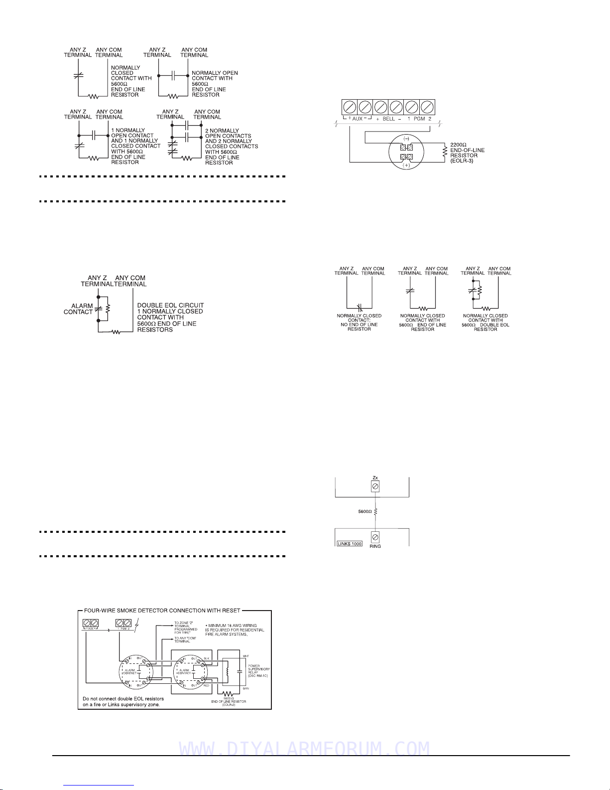
2.10 Zone Wiring
For a complete description of the operation of all zone
types, see section ’Basic Programming PWS Sect 3’.
There are several different ways in which zones may be
wired, depending on which programming options have
been selected. The panel can be programmed to supervise
normally closed, end of line, or double end of line loops.
Refer to the following sections to study each type of individually supervised zone wiring.
NOTE:
must be wired with a single end of line (EOL) resistor regardless of the type of zone wiring supervision selected for the
panel (section [013], options [1] and [2]). See Zone Definitions [001]-[002]. If you change the zone supervision options
from DEOL to EOL or from NC to DEOL (section [013],
options [1] or [2]), power the system down completely, and
then power it back up for correct operation.
Normally Closed (NC) Loops
To enable normally closed loops, programming section
[013], option [1] must be ON.
NOTE:
Closed (NC) devices/contacts are being used.
Normally Closed Loops. . . . . . . . . . . . . . . Section [013], Option [1]
Single End Of Line (EOL) Resistors
To enable panel detection of single end of line resistors,
programming section [013], options [1] and [2] must be
OFF.
NOTE:
Closed (NC) or Normally Open (NO) detection devices or contacts are being used.
Any zone programmed for Fire or 24-hr Supervisory
This option should only be selected if Normally
ANY Z
TERMINAL
ANY COM
TERMINAL
This option should be selected if either Normally
ANY Z
TERMINAL
ANY COM
TERMINAL
WWW.DIYALARMFORUM.COM
8
Installation and Wiring:
2.10 Zone Wiring
Fire Zone Wiring - 2-wire Smoke Detectors
If PGM2 has been programmed for 2-wire smoke detector
connection (see section ’Basic Programming PWS Sect 3’),
the detectors must be wired according to the following
diagram:
End of Line Resistors . . . . . . . . . . . . . . . . Section [013], Option [1]
Single End of Line Resistors . . . . . . . . . . . Section [013], Option [2]
Double End of Line (DEOL) Resistors
Double end of line resistors allow the panel to determine
if the zone is in alarm, tampered or faulted.
To enable panel detection of double end-of-line resistors,
programming section [013], option [1] must be OFF and
option [2] must be ON.
NOTE:
hardwired zones must be wired for double EOL resistors,
except for Fire and 24-hr Supervisory zones.
Do not wire DEOL resistors on keypad zones.
Do not use DEOL resistors for Fire zones or 24-hr Supervisory
zones. Do not wire Fire zones to keypad zone terminals if
the DEOL supervision option is selected.
This option can only be selected if Normally Closed (NC)
detection devices or contacts are being used. Only one NC
contact can be connected to each zone.
If the double EOL supervision option is enabled, all
The following chart shows zone status under certain conditions:
Loop Resistance Loop Status
0Ω (shorted wire, loop shorted) Fault
5600Ω (contact closed) Secure
Infinite (broken wire, loop open) Tamper
11200Ω (contact open) Violated
End-of-Line Resistors . . . . . . . . . . . . . . . . Section [013], Option [1]
Double End-of-Line Resistors . . . . . . . . . . Section [013], Option [2]
Fire Zone Wiring - 4-wire Smoke Detectors
(
All zones defined as Fire
PWS Sect 3’
)
must be wired according to the following
see section ’Basic Programming
diagram:
For a complete description of how fire zones operate, see
section ’Basic Programming PWS Sect 3’
.
NOTE:
Jumper CON1 on the main board must be removed.
If PGM2 is programmed for 2-wire smoke support,
For a complete description of how fire zones operate, see
section ’Basic Programming PWS Sect 3’
.
Keyswitch Zone Wiring
Zones may be programmed to be used as keyswitch arming zones and must be wired according to the following
diagram:
For a complete description of how keyswitch zones operate, see section ’Basic Programming PWS Sect 3’
.
LINKS1000 Supervisory (24-hr Supervisory)
When using the LINKS1000 cellular communicator, any
main board zone may be configured for LINKS1000 Supervision. Program this zone as zone type (09), 24-hr Supervisory in section [001].
With a 24-hr Supervisory zone, if the LINKS1000 experiences a trouble, the zone will be violated, causing the
panel to report the event to the central station. This type
of zone
(5600Ω).Refer to LINKS 1000
always
requires a single EOL resistor
Installation Manual
wiring
diagram for installation.
LINKS1000 Answer
If the LINKS1000 cellular communicator is being used a zone may
be configured for LINKS1000
Answer to allow downloading to
be performed in the event of telephone line failure. When the
LINKS1000 receives a telephone
call it will activate the RING terminal on the LINKS1000 circuit board. This terminal can be
used to violate a zone programmed as (24) LINKS1000
Answer
(
see section ’Basic Programming PWS Sect 3’),
causing the panel to seize the telephone line and begin
communication with the downloading computer.
The zone programmed as LINKS1000 Answer ALWAYS
requires a single EOL resistor (5600Ω) and must be wired
according to the diagram above.
NOTE:
downloading to the panel via the LINKS1000, or for
remotely connecting to the Escort5580(TC) module via the
LINKS1000.
NOTE:
must not be used.
NOTE:
or LINKS1000 Answer.
The LINKS1000 Answer zone is only required for
When using the LINKS1000, Busy Tone Detection
Keypad zones cannot be used for 24-hr Supervisory
WWW.DIYALARMFORUM.COM
9
LINKS 2X50/LINKS 3000/Skyroute™
Refer to the LINKSX50, LINKS3000 and Skyroute™
Installation Manuals
for wiring and installation details.
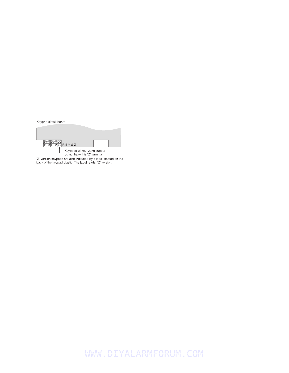
2.11 Keypad Zones
Keypads with zone inputs can be connected to devices
such as door contacts. This saves you from running wires
back to the control panel for every device.
To install the keypad, open the keypad plastic by removing the screw at the bottom of the unit. Locate the five terminals on the keypad circuit board. Connect the four
Keybus wires from the control panel: the red wire to R,
the black to B, the yellow to Y and the green to G.
To connect the zone, run one wire to the Z terminal and
the other to B. For powered devices, use red and black to
supply power to the device. Run the red wire to the R
(positive) terminal and the black wire to the B (negative)
terminal.
When using end of line supervision, connect the zone
according to one of the configurations outlined in section
2.10 ‘Zone Wiring‘.
NOTE:
end of the loop, not at the keypad.
NOTE:
Assigning Keypad Zones
When using keypad zone inputs, each input used must be
assigned a zone number in Installer Programming.
First, ensure that you have enrolled all installed keypads
into the desired slots (see section ’Keypad Assignment’
Next, enter programming section [020] to assign the
zones. There are eight programming locations in this section, one for each keypad slot. Enter a 2-digit zone number for each of the keypad zones. This number must be
entered in the location corresponding to the keypad to
which each zone is connected.
NOTE:
bered from 1 to 8, the corresponding zone cannot be used
on the main control panel.
Once the keypad zones are assigned, you must also program
zone definitions and zone attributes (see section 5.3 Basic
Programming and Section 5.4 Advanced System Programming).
NOTE:
occupied by a zone expander.
End of line resistors must be placed on the device
Keypad zones do not support DEOL resistors.
).
If a keypad zone input is assigned on a zone num-
A keypad zone cannot be added to zones already
WWW.DIYALARMFORUM.COM
10

Section 3: How to Program
The following section of the manual describes how to
enter Installer Programming and how to program the various sections.
NOTE:
ing section of the manual to completely understand how to
program the panel.
It is extremely important that you read the follow-
3.1 How to Enter Installer Programming
Installer Programming is used to program all communicator and panel options. The Installer Code
default, but should be changed to prevent unauthorized
access to programming.
NOTE:
Once Installer Programming is exited, the system will
reset. This will take 15 seconds. Do not attempt to perform
any system function during this reset period. In addition, all
outputs will return to their normal, deactivated state (or
activated if inverted).
LED Keypad
Step 1:
Step 1: From any keypad enter [*][8][Installer Code].
Step 1:Step 1:
• The ‘Program’ light will flash to indicate you are in
programming
• The ‘Armed’ light will turn on to indicate the panel is
waiting for the 3-digit Section number to program
Step 2:
Step 2: Enter the 3-digit Section number you want to pro-
Step 2:Step 2:
gram.
• The Armed light will turn off
• The Ready light will turn on to indicate the panel is
ready for the information for the selected Section
NOTE:
the module that pertains to the Section is not present, the
keypad will sound a 2-second beep or error tone.
LCD Keypad
Step 1:
Step 1: From any keypad enter [*][8][Installer Code]. The
Step 1: Step 1:
Step 2:
Step 2: Enter the 3-digit Section number you want to pro-
Step 2: Step 2:
Installer Code . . . . . . . . . . . . . . . . . . . . . . . . . . . . . . Section [006]
If the 3-digit section number entered is not valid or
keypad will display ‘Enter Section’ followed by three
dashes.
gram. The keypad will now display information for
the section entered.
Installer Code is [5555] at
Installer CodeInstaller Code
3.2 Programming Decimal Data
When the Ready light is ON the panel is waiting for the
information to be programmed for the selected Section.
Enter the information written in the boxes for the Section
found in the
If a digit is entered for each program box in a Section the
panel will automatically exit from the Section. It will turn
OFF the Ready light and turn the Armed light back ON.
You can also press the [#] key to exit a Section before
entering data for every box. This is handy if you only
need to change the first few program boxes. All other
locations in the Section will remain unchanged. If the [#]
key is pressed the panel will turn OFF the Ready light,
turn ON the Armed light and exit you from the Section.
Programming Worksheets
.
3.3 Programming Hexadecimal Data
On occasion, hexadecimal (Hex) digits may be required.
To program a Hex digit press the [*] key. The panel will
enter Hex programming and Ready light will begin to
flash.
The following table indicates which number should be
pressed to enter the corresponding Hex digit:
1 = A 2 = B 3 = C 4 = D 5 = E 6 = F
After the correct Hex digit is entered the Ready light will
continue to flash. If another Hex digit is required press
the corresponding number. If a decimal digit is required
press the [*] key again. The Ready light will turn on solid
and the panel will return to regular decimal programming.
NOTE:
is flashing any number you enter will be programmed as the
Hex equivalent.
Example: To enter ‘C1’ for a closing by user 1, you would
enter [*] [3] [*], [1]
[*] to enter Hexadecimal mode (Ready light flashes)
[3] to enter C
[*] to return to decimal mode (Ready light is solid)
[1] to enter digit 1
If you enter information into a section and make a mistake, press the [#] key to exit the section. Select that sec-
tion again and re-enter the information correctly.
If you are using a pulse communications format, a deci-
mal zero [0] does not transmit. Programming a zero [0]
tells the panel not to send any pulses for that digit. Decimal zero [0] is a filler digit. To make a zero [0] transmit, it
must be programmed as a Hexadecimal ‘A’.
Example: for the 3-digit account number ‘403’, you would
enter [4], [*] [1] [*] [3], [0].
[4] to enter the digit 4
[*] to enter Hexadecimal mode (Ready light flashes)
[1] to enter A
[*] to return to decimal mode (Ready light is solid)
[3] to enter the digit 3
[0] to enter the digit 0 as a filler digit.
It is important to watch the Ready light. If the light
3.4 Programming Toggle Options
Some Sections contain several toggle options. The panel
will use zone lights 1 through 8 to indicate if the different
options are enabled or disabled. Refer to the
ming Worksheets
sents and whether the light should be ON or OFF for your
application.
Press the number corresponding to the option to toggle
the light ON or OFF.
Once all the toggle options have been selected correctly
press the [#] key to exit the Section and save the changes.
The panel will turn off the Ready light and turn on the
Armed light.
to determine what each option repre-
Program-
WWW.DIYALARMFORUM.COM
11
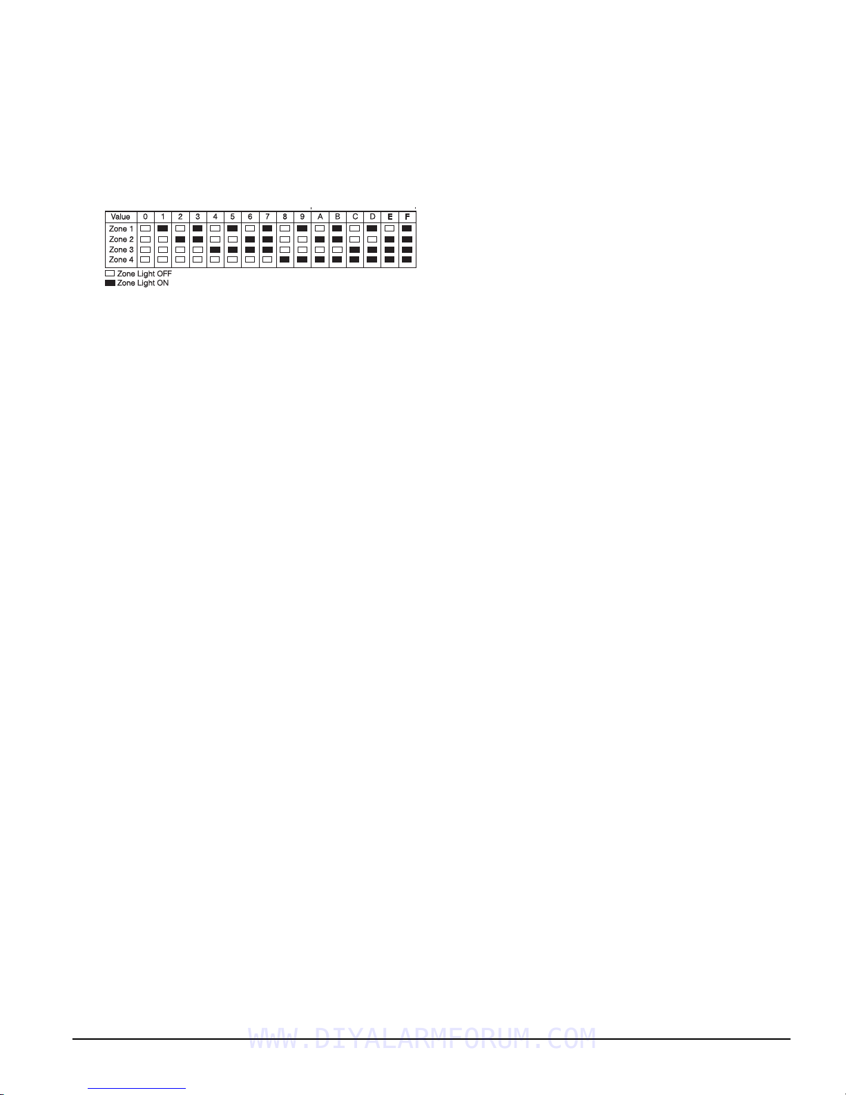
3.5 Viewing Programming
LED and LCD5501Z Keypads
Any programming section can be viewed from an LED or
LCD5501Z keypad. When a programming section is
entered, the keypad will immediately display the first
digit of information programmed in that section.
The keypad displays the information using a binary format, according to the following chart:
See Hex data
entry instructions
Press any of the Emergency keys (Fire, Auxiliary or Panic)
to advance to the next digit.
When all the digits in a section have been viewed, the
panel will exit the section: the Ready light will turn OFF,
and the Armed light will turn ON, waiting for the next
three-digit programming section number to be entered.
Press the [#] key to exit the section
LCD Keypad
When a programming section is entered, the keypad will
immediately display all the information programmed in
that section. Use the arrow keys (< >) to scroll through the
data being displayed. To exit the section, scroll past the
end of the data displayed, or press the [#] key.
WWW.DIYALARMFORUM.COM
12
 Loading...