

DSC PC560, PC500RK, SL-40 Installation Manual

INSTALLATION
MANUAL
PC56O
Version 1.OA

TABLE OF CONTENTS
INTRODUCTION 3
Features .................................................................................................................................................. 3
Specifications.......................................................................................................................................... 3
INSTALLATION 4
Mounting the Control Panel..................................................................................................................... 4
Mounting the Keypad.............................................................................................................................. 4
Wiring ...................................................................................................................................................... 5
Burglary Zone Wiring .............................................................................................................................. 5
Auxiliary Power Connection .................................................................................................................... 5
PGM OUT Terminal Connection.............................................................................................................. 5
STR Terminal Connection ....................................................................................................................... 6
KEY Terminal Connection ....................................................................................................................... 6
Battery Connection ................................................................................................................................. 6
AC Power Wiring ..................................................................................................................................... 6
Telephone Line Wiring ............................................................................................................................ 6
KEYPAD FUNCTIONS 7
Introduction ............................................................................................................................................. 7
Master Code............................................................................................................................................ 7
Installer’s Programming Code ................................................................................................................ 7
Arming..................................................................................................................................................... 7
Auto-Bypass/Home-Away Arming .......................................................................................................... 7
At-Home Arming...................................................................................................................................... 7
Disarming ................................................................................................................................................ 8
Important Note about Keypad [
[∗]+[0]: Quick-Arm................................................................................................................................ 8
[∗]+[1]+[Access Code]: Zone Bypassing............................................................................................8
[
]+[2]: Display Trouble Conditions ..................................................................................................... 8
∗
[∗]+[3]: Display Alarm Memory ............................................................................................................ 9
[∗]+[4]: Bell Test ................................................................................................................................... 9
[∗]+[5]+[Master Code]: Program Access Codes................................................................................. 9
[∗]+[6]: Door Chime On/Off .................................................................................................................. 9
[∗]+[8]+[Installer’s Code]: Installer’s Programming Command........................................................... 9
[
]+[9]: At-Home Arming .................................................................................................................... 10
∗
Keypad Zones....................................................................................................................................... 10
Adjusting the Keypad Sounder Tone and Backlighting ....................................................................... 10
] Commands ...................................................................................... 8
∗
1

PROGRAMMING GUIDE 11
Sections [05] through [07]: Selecting System Functions ..................................................................... 11
HEX Data Programming ........................................................................................................................ 11
Resetting Programming to the Factory Default Settings....................................................................... 11
PROGRAMMING SECTIONS 12
[01] Zone Definitions ............................................................................................................................ 12
[02] System Times ................................................................................................................................ 13
[03] Installer’s Code ............................................................................................................................. 13
[04] Programmable Output Options (PGM OUT Terminal) .................................................................. 13
[05] 1st System Option Code ............................................................................................................... 14
[06] 2nd System Option Code.............................................................................................................. 14
[07] 3rd System Option Code............................................................................................................... 15
[08] First Phone Number ...................................................................................................................... 16
[09] Second Phone Number................................................................................................................. 16
[10] Customer Account Code .............................................................................................................. 1 6
Disabling Communications ................................................................................................................... 16
[11] Zone Alarm and Restoral Reporting Codes.................................................................................. 16
[12] Closing and Opening Reporting Codes ....................................................................................... 16
[13] Maintenance and Priority Codes................................................................................................... 17
[14] Downloading Access Code .......................................................................................................... 17
FOR THE RECORD 18
PROGRAMMING WORKSHEETS 19 - 22
HOOK-UP DIAGRAM 23
LIMITED WARRANTY 24
2

INTRODUCTION
FEATURES
• Fully featured security system with Trouble
Supervision, Alarm Memory, Master Code and 3
programmable Access Codes, Quick-Arming and
At-Home Arming, Door Chime, 3 one-touch Keypad
Zones, and more
• Digital Communicator with 40 BPS Non-Extended
4/2 with Parity format or Private Line format
• 4 End-of-Line Resistor Supervised Zones
• 6 Programmable Zone Types with Silent or Audible
alarms
• Programmable Output with 2 options
• Dedicated Strobe (latched alarm) Output
• KEY Terminal can be used for Momentary or
Maintained Keyswitch Arming, or as a 24-hour Endof-Line Resistor Supervised Tamper Zone
• To help prevent false alarms, all zones are
automatically bypassed for 120 seconds on powerup to allow detectors to settle
• All Installer’s Programming can be done at the
keypad or through downloading
• EEPROM memory retains all programming even
after all power is removed from the control panel
• Advanced static and lightning protection; unique
“Zap-Trac” circuit board design stops damaging
voltages at the wiring terminals, and transient
protection devices are placed in all critical areas for
further protection
SPECIFICATIONS
PC560 Control Panel
• Four fully programmable zones
• Zones are End-of-Line Resistor supervised
• Maximum zone loop resistance: 100 ohms
• Bell/Siren Output: fused for 5A
• Bell / Siren Alarms: steady and pulsed alarms
• Programmable Output: 300 mA with 2 options
• Auxiliary Power Output:
• 800 mA with 40 VA transformer
• 500 mA with 20 VA transformer
• Maximum 3 Keypads per system, and Keyswitch
• Required Battery: 12 V
• 1.2 Ah provides 4 hours of stand-by at
200 mA Auxiliary Output
• 4.0 Ah provides 4 hours of stand-by at
800 mA Auxiliary Output
• Required Transformer: 16 V
• Cabinet Dimensions: 7" high × 9" wide × 3" deep
(178 × 229 × 76 mm)
• Cabinet Colour: light beige
PC500RK Keypad
• 12-key keypad
• Three one-touch Zones: [F], [A], [P]
• 3 Status Lights: Ready, Armed, System
• 4 Zone Lights
• Keypad dimensions: 4.5" high × 4.5" wide × 1"
deep (114mm × 114mm × 25.4mm)
• Keypad Colour: Mist
DC
AC, 20 - 40 VA
SL-40 Keypad
• 12-key keypad
• Three one-touch Zones: [F], [A], [P]
• 3 Status Lights: Ready, Armed, System
• 4 Zone Lights
• All new slimline design
• Keypad dimensions: 4.75" high × 2.75" wide × 1.2"
deep (120mm × 70mm × 30mm)
• Keypad Colour: Designer White with Grey display
3
INSTALLATION
Mounting the Control Panel
Select a dry location close to an unswitched AC source, a ground connection, and the telephone connection.
Remove the printed circuit board, mounting hardware and keypad from the cardboard retainer inside the
control panel cabinet. Before attaching the cabinet to the wall, press the four white nylon printed circuit board
mounting studs into the raised mounting holes from the back of the cabinet. Also, secure the ground screw to
a hole in the cabinet.
Hold the cabinet in position and pull all wires into the cabinet. Mount the cabinet securely to the wall using the
mounting screws provided. It is recommended that appropriate wall anchors be used when securing the
cabinet to drywall, plaster, concrete, brick or other similar surfaces.
Press the PC560 Control Panel onto the nylon mounting studs. Pull all cables into the cabinet and prepare them
for connection.
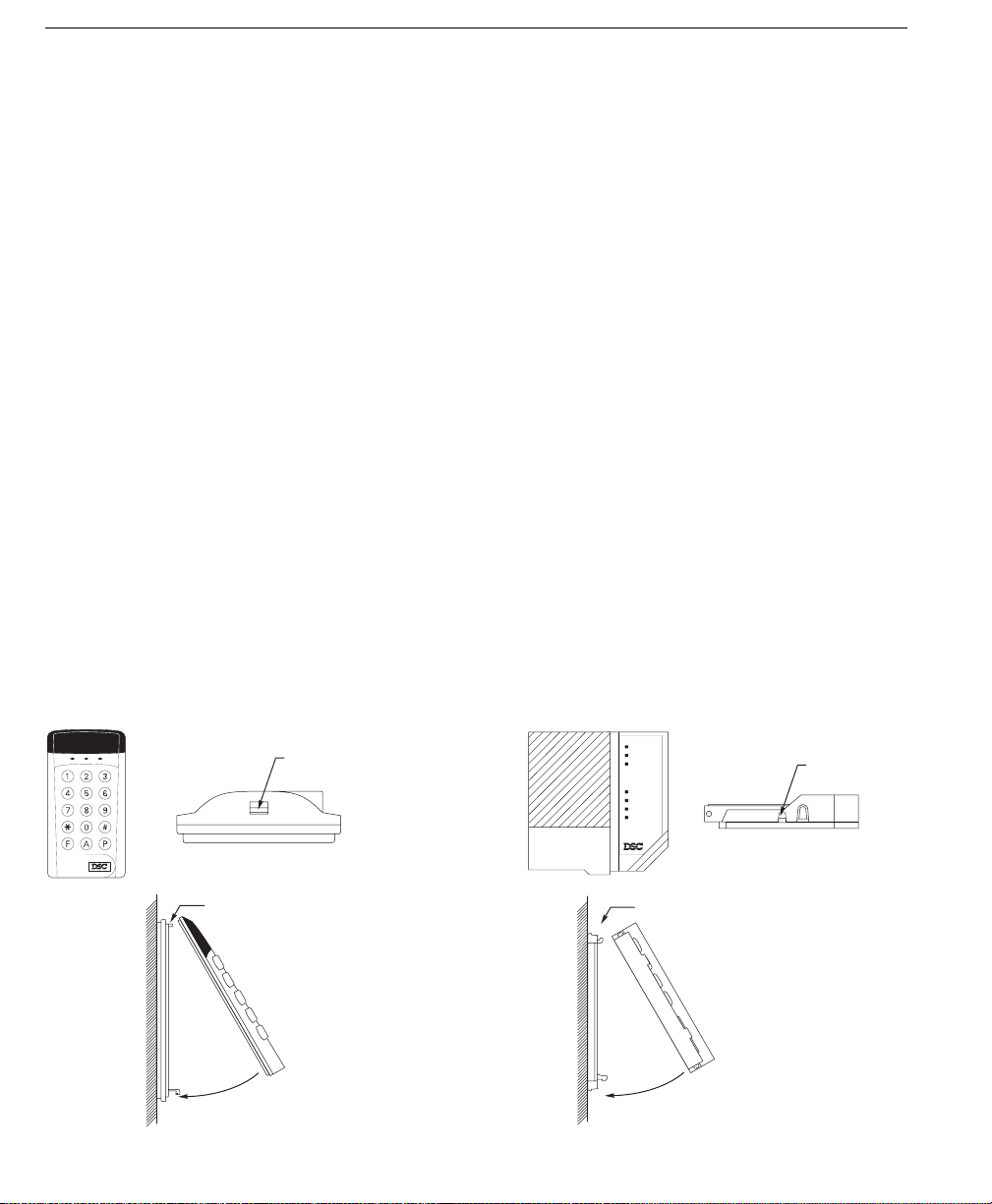
Mounting the Keypad
The PC560 Control Panel is controlled with the PC500RK or SL-40 Keypad. The Keypad should be located close
to the designated “Entry-Exit” door and mounted at a height convenient for all users.
Disassemble the keypad by pressing gently on the locking tab found on the bottom of the unit. With the tab
disengaged, pull the backplate from the keypad.
Prepare a hole in the wall at the desired location and pull the keypad wiring through the hole. Hold the backplate
in position and pull the wires through the large opening in the backplate. Mount the backplate to the wall using
the hardware provided; it is recommended that plastic wall anchors be used. When mounting the backplate,
ensure that it is straight and level.
Prepare all wires for connection and connect the keypad wires to the in-wall wiring; refer to the Wiring Diagram
in the back of this manual.
Align the keypad with the mounting tabs on the top of the backplate. With the top mounting tabs engaged, swing
the keypad down and engage the bottom locking tab. Ensure that the top mounting tabs and the bottom locking
tab are securely engaged.
SL-40 Keypad PC500RK Keypad
1234
4
WALL
LOCKING TAB
SL-40 KEYPAD
BOTTOM VIEW
ENGAGE TOP TABS FIRST
RE-ASSEMBLY OF
SL-40 KEYPAD
SIDE VIEW
(WIRES NOT SHOWN
FOR CLARITY)
SWING KEYPAD DOWN
TO ENGAGE LOCKING TAB
WALL
Ready
Armed
System
Zone 1
Zone 2
Zone 3
Zone 4
PC500RK KEYPAD
BOTTOM VIEW
ENGAGE TOP TABS FIRST
RE-ASSEMBLY OF
PC500RK KEYPAD
SIDE VIEW
(WIRES NOT SHOWN
FOR CLARITY)
SWING KEYPAD DOWN
TO ENGAGE LOCKING TAB
LOCKING TAB

Wiring
Wire
Gauge
1900 / 579
3000 / 914
2400 / 1493
6200 / 1889
7800 / 2377
24
22
20
19
18
Maximum wire length to
End of Line Resistor
(feet/meters)
Figures are based on maximum loop
resistance of 100 ohms.
Burglary Zone Wiring Chart
NOTE: Complete all wiring to the control panel before applying battery or AC power.
Burglary Zone Wiring
Burglary zone definition, (for example, Delay, Instant, 24-Hour, and so on) is programmed using the keypad.
Refer to Programming Guide Section [01].
NOTE: To help prevent false alarms, all zones are automatically bypassed for 120 seconds on power-up to allow
detectors to settle.
COM Z2
Z1
Auxiliary Power Connection
The Auxiliary Power Supply can be used to power motion detectors and other devices that require 12 VDC. The
total load for the Auxiliary Power Supply must be calculated for all devices connected across the AUX+ and
AUX-, AUX+ and STR terminals, and for devices connected between the AUX+ and PGM terminals. The output
current cannot exceed 800 mA when using a 40VA transformer.
PGM OUT Terminal Connection
The PGM OUT terminal is a switched negative output which can be controlled by various programming options;
refer to Programming Guide Section [04]. Devices controlled by the PGM OUT terminal must be connected
between the PGM OUT terminal and the AUX+ terminal.
EOL RESISTOR
LOOPS USING
NO & NC
DEVICES
NC
END OF LINE
RESISTOR
5600Ω 0.5W
NO
NC
NC
END OF LINE
RESISTOR
5600Ω 0.5W
EOL RESISTOR
LOOPS USING
NC DEVICES
ONLY
5
STR Terminal Connection
The STR (strobe output) terminal is a normally open output that will switch to ground when activated. This output
will be activated when a zone alarm or tamper alarm is generated while the system is armed. The output will
remain activated until the system is disarmed. Devices controlled by this output must be connected between
STR and the AUX+ terminal.
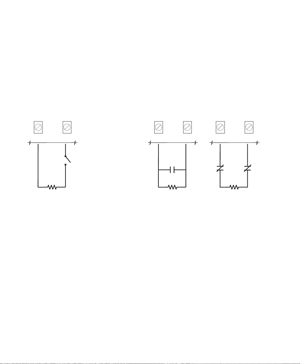
KEY Terminal Connection
The KEY terminal may be programmed for keyswitch operation or for use as a tamper zone. If the KEY terminal
is used as a tamper zone, the zone is wired as a typical burglary zone. The tamper zone is active at all times
and will generate alarm and trouble conditions even while the system is disarmed.
NOTE: An end-of-line resistor must be connected between the KEY and COM terminals even if the tamper zone
is not used.
KEYSWITCH
OPERATION
TAMPER ZONE
N.O. CONTACTS
TAMPER ZONE
N.C. CONTACTS
KEY
END OF LINE
RESISTOR
5600Ω 0.5W
COM
MOMENTARY OR
MAINTAINED CONTACT
KEYSWITCH
KEY
END OF LINE
RESISTOR
5600Ω 0.5W
COM
KEY
END OF LINE
RESISTOR
5600Ω 0.5W
COM
Battery Connection
The control panel will not power up on DC (battery) power only. With the battery connected, apply AC
power to power up the panel.
If the battery is connected in reverse, the 5 A battery fuse will open and will need to be replaced. The battery
charging voltage is factory set to 13.8V and normally needs no adjustment. If the battery charging voltage is
out of adjustment, contact your service representative.
If AC power is OFF and the battery voltage drops to approximately 9.5 V or lower, the battery will be automatically
disconnected and the system will power down. To power up again, AC power will have to be re-established.
This feature is designed to prevent damage to the battery due to deep discharging.
AC Power Wiring
Complete all wiring to the control panel before connecting AC power or the battery. The transformer should
not be connected to an outlet that is controlled by a switch.
Telephone Line Wiring
Do not connect the alarm communicator to telephone lines intended for use with facsimile (fax) machines.
These lines may incorporate a voice filter which disconnects the line if other than fax signals are detected. This
may result in incomplete transmissions from the alarm communicator.
6

KEYPAD FUNCTIONS
Introduction
The Keypad provides complete control of the PC560 control panel. The system can be completely programmed
from the keypad. The 4 zone lights provide alarm and status indication for the alarm circuits, and three function
lights advise the user of system status. The built-in sounder lets the user hear correct key entries and other alert
signals. Keypad alarms may be activated by pressing and holding the [F], [A] or [P] Keys. Note that all keypad
entries are made by pressing one key at a time.
Master Code
A default Master Code “1234” is factory programmed into the PC560. The Master Code is used to arm and
disarm the system, to silence the bell or siren after an alarm, and to program additional Access Codes. The
Master Code may be changed by the user through the [∗][5][Master Code] Program Access Codes command.
Installer’s Programming Code
A default Installer’s Programming Code “0560” is programmed into the PC560. Using this code and the [∗][8]
command, the installer can perform programming functions. This code should be changed by the installer after
the system is installed.
Arming
Before arming the system, close all protected doors and windows and stop movement in areas protected by
motion detectors. If the “System” light is on, check for possible trouble conditions (refer to [∗][2]: Display
Troubles) and correct the condition. Ensure that any bypassed zones are bypassed intentionally; refer to
[∗][1][Access Code]: Bypass Zones. If the “Ready” light is not on, one or more zones are open; the system
can only be armed when the “Ready” light is ON.
To arm the system, enter a 4-digit Access Code. As each digit is entered, the keypad sounder will beep. When
the Access Code has been entered, the “Armed” light will come ON and the keypad will beep 6 times. If the
Access Code has been entered incorrectly, the keypad will sound a single long tone; press the [#] Key and enter
the Access Code again.
When an Access Code has been entered and the “Armed” light is ON, leave the premises through the
designated Entry-Exit door before the Exit Delay expires. At the end of the Exit Delay, all lights on the keypad
will be shut OFF except for the “Armed” light.
The default setting for the Exit Delay is 60 seconds. Refer to Programming Section [01] Zone Definitions for
information on zone types that are affected by the Exit Delay. Also refer to Programming Section [02] for
instructions on changing the Exit Delay. If an alarm occurs during the armed period, the Zone Light for the
affected zone will remain ON until the system is disarmed.
Auto-Bypass/Home-Away Arming
If an Access Code is entered and the Exit-Entry zone is not activated during the Exit Delay, the system will arm
with all Home-Away zones automatically bypassed. If the Exit-Entry zone is activated during the Exit Delay, the
Home-Away zones will not be bypassed. If a standard Delay zone is activated while the system is armed, all
automatic bypasses will be removed.
This feature is designed for the user who wishes to remain at home with the system armed. When this feature
is enabled, the user does not have to manually bypass the interior zones.
At-Home Arming
When [∗][9] is entered to arm the system, the system will arm as described above in Auto-Bypass/Home-Away
Arming. However, an exit may be made through the Entry-Exit Zone during the Exit Delay; at the end of the Exit
Delay, the system will be armed and Home-Away zones will be automatically bypassed. Note that the Entry
Delay will still be applied to standard Delay zones.
7
 Loading...