

DSC PC4820 User Manual

Introduction
S e c t i o n 1
The PC4820 is a versatile Dual Card Reader Access Control
module which will enable you to meet the most
demanding access control requirements of an installation.
The PC4820 is monitored and programmed via the
PC4010/4020 control panel. Up to 16 PC4820 modules can
be connected to a PC4010/4020 via a 4-conductor Combus,
using standard, unshielded station wire.
Each PC4820 is capable of providing supervision for two
door inputs which may to assigned to any PC4010/4020
zone. Each door contact may be configured for any zone
end of line option which the control panel can provide.
Each of the two PC4820 Access Card Readers can be
programmed to function independently on different
doors, or together controlling access for both sides of one
door.
Control of the access points can be performed using a
variety of equipment. The PC4820 supports four different
types of card readers: the Polaris magnetic strip reader,
the Shadow Prox proximity card reader, the HID proximity
readers, and 26-bit standard Wiegand card readers. The
PC4820 also supports the use of any request to exit device
including the T-REX exit detector.
1.1 PC4820 Access Control Module
Specifications
Two Zone Inputs
• Two programmable supervised zones ( EOL resistors
– value )
• Zones may be programmed as Standard or Auxiliary
delay zone types
• PC4010/4020: up to 16 PC4820 can be added (up to
32 access points)
Non Volatile RAM (internal memory)
• Does not lose any system programming when the
module is powered down.
Low Current Outputs
• Six low current outputs (open collector outputs
switched to ground 25mA max.) :
• Two LED terminals - To the LED input of the
reader
• Two BUZ terminals - To the Buzzer input of the
reader
• Two OUT terminals - Reserved for future use
Regulated Power Supply ( 1.5 Amp max. )
• Electronic shutdown protection of the battery,
auxiliary output, 5 and 12 V reader power supplies,
and lock device power output
• Auxiliary output supply: 12V
• LK1 and LK2 Door Strike power: 12V
• Reader Power 5V
• Reader Power 12V
DC, 125mA Max
DC, 125mA Max
DC, 125mA Max
DC, 250mA Max
Reader Technology
• Polaris, Shadow Prox, HID Proximity and 26-bit
Standard Weigand format
Access Card Compatibility
• Polaris POL-C1CN - Polaris Magnetic Cards
• Shadow Prox, Module Numbers:
SH-C1 - Shadow Prox Card
SH-K1 - Shadow Prox Keytag
• HID Proximity:
HID-C1325KSF - Proximity Card
HID-C134KSP - Proximity Keytag
• Weigand - Standard 26 bit formats
Battery
DC 7.0Ah recommended rechargeable gel-cell
• 12V
Transformer
• 16.5 V
AC, 40VA
Operating Temperature
°
C to 40°C (35°F to 110°F) operational Temperature
•2
Range
°
non-condensing humidity
•90
Output Voltage
• Output voltage = 13.8V
DC (with normal AC and a
fully charged battery). Devices that require power
from the PC4820 should be capable of operation over
the voltage range of 10 to 14V
DC.
• 5V Power Supply - Devices connected to the 5V
supply should be capable of operation between 4 and
6V.
1
Installation and Wiring
S e c t i o n 2
2.1 Plan Your Installation
When designing a security system with access control it
is best to first lay out the system on paper. This will help
determine the total number of zones, additional expanders,
access control points and other system components that
will be required to complete the installation.
When the location of all points of access are known,
appropriate points may be chosen for access control. When
working from the layout, be sure to locate the PC4820
module so that the wire runs from each door will be as
short as possible.
When deciding the placement of the access points and
module, remember to check the capacitance limit for the
wire you are using for the Combus. Follow the steps
outlined in your PC4010/4020 v3.0 Installation Manual
(Section 2.4 “Capacitance Limits”).
NOTE: Do not run the Combus to the PC4820 in shielded
cable.
2.2 Installation Steps
Once the location of the PC4820 and each access point is
determined, follow the installation steps outlined below.
1 Installation of PC4820 and accessories:
The PC4820 controller cabinet has been designed for
surface mounting. The cabinet is large enough to
accommodate the battery backup supply and the
necessary wiring connections for most applications.
The cabinet should be mounted indoors, in a dry,
secure location providing normal temperature,
humidity levels and access to an earth ground
connection. The location should be easily accessible
for servicing the equipment, and it is recommended
that each PC4820 module be near the doors it controls.
If the PC4820 is within the Access controlled area, keys
for the controlled doors must be made available so
that the PC4820 can be accessed for servicing.
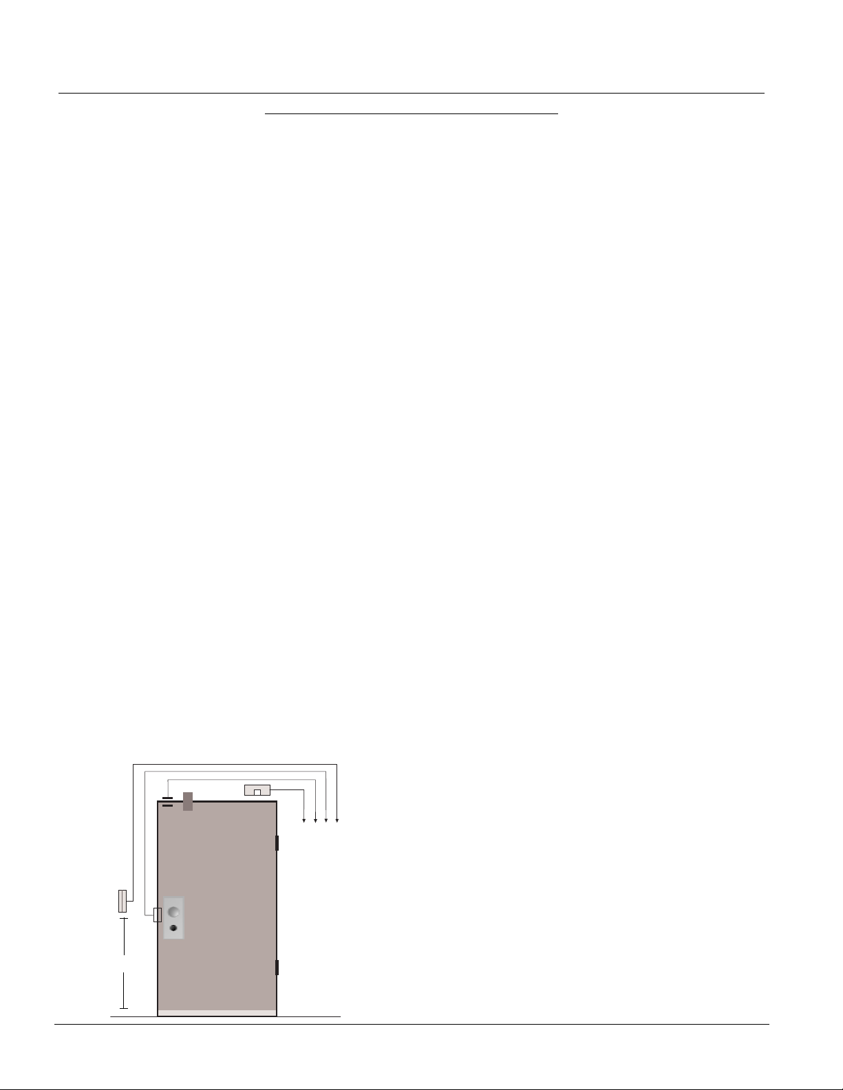
Connect the various devices for each access door
according to the diagram below:
C
D
To PC4820 Access
Control Module (See
Access Control
Module Wiring
Diagrams for details)
B
A
A. Access card readers should be located 107cm (42")
from the floor.
B. Connect door strikes using standard 18-gauge cable.
Recommended door strikes are electric “Continuous
Duty” devices which, when power is cut, will remain
in a locked or “secured” state. When using magnetic
locks, follow local regulations on the use of these
devices.
CAUTION – Local regulations may prohibit “Lock on
Power Failure” if the door is used as a Fire Escape route.
C. Door contact must be hardwired directly to the PC4820.
Wireless or addressable contacts may not be used.
D. Install a T-REX exit detector and door alarm (optional)
inside of the protected area. (See T-REX Installation
Instructions for details on wiring and proper
mounting locations.)
2 Tamper protection
A tamper switch may be installed on the cabinet to
protect it from unauthorized entry. The normally
closed tamper switch is connected to the TAMP and
GND (on right side of the PC4820). If the tamper
switch is not used, the TAMP terminal must be
terminated to any GND terminal with a wire.
3 Connect all inputs, outputs, door locking
devices and card readers
Follow the instructions outlined in the sections
below for installing each type of device.
4 Power requirements
Install a 16-18V
cabinet. Connect the red battery lead to the positive
terminal and the black battery lead to the negative
terminal.
NOTE: Do not apply power until all wiring is complete.
Both the AC and battery connections must be made in
order for the PC4820 to function properly. Connect
the battery before connecting the AC.
AC/40VA transformer outside the
2.3 Inputs – POST, ARM and REX
The door inputs are capable of following any type of
supervision. Choose the end of line configuration (Normally
Closed Loops, Single End of Line or Double End of Line)
which you have selected for the rest of the security system.
The POST, ARM and REX inputs are for Auto-arm
postponement, Arming buttons and Request to Exit
devices, respectively. These inputs will only be capable of
Normally Closed Loops or Single End of Line resistors.
When using Double End of Line supervision, these inputs
must only be wired for Single End of Line configuration.
Please see section 3.5 “Zone Assignment for Access Doors”
for information on door input zone programming.
POST Inputs
When enabled, this PC4820 input allows postponement of
Autoarm of the PC4010/4020 for the partitions selected in
2

Installation and Wiring
the Arm/Disarm mask. To postpone an autoarm, the user
must present their access card (during the autoarm prealert) and activate the device connected to the POST input.
Typically the POST input will be a push button device
mounted next to the access card reader (107cm (42") from
the floor) which is assigned to the partition(s).
The PC4010/4020 will send an Autoarm Abort reporting
code to the monitoring station if the reporting code is
programmed. The autoarm will restart at the end of the
Postpone Arm time (ref # [00020305]) unless the partition
has been manually rearmed. The autoarm may be
postponed as many times as desired.
NOTE: To postpone an autoarm, the user must be
assigned to the partition(s) being armed, and the user’s
access card must have the disarm attribute enabled.
See your PC4010/4020 Instruction Manual for
information on programming access codes and cards.
ARM Inputs
When enabled, this PC4820 input will allow designated
users to arm the selected partitions on the PC4010/4020.
To arm the partition, the user must first ensure that the
partition area(s) to be armed is secure (close all protected
doors and stop movement in areas covered by motion
detectors). The user should present the access card and
activate the device connected to the ARM input. The exit
delay will begin. Typically the ARM input will be
connected to a push button device and should be
mounted next to the access card reader (107cm (42") from
the floor) which is assigned to the partition(s).
NOTE: To arm partitions, the user must be assigned to
the partition(s) being armed, and the user’s access card
must have the arm attribute enabled. See your PC4010/
4020 Instruction Manual for information on
programming access codes and cards.
REX Inputs
A Request to Exit device can be used on the inside of the
secured area to provide a method of unlocking the door
without the need for an access card reader on the inside
of the door. When the REX device is tripped, the door
will unlock. This will also allow the door to be opened
without the door being “Forced open.” Request to exit
devices can be of many different types. Be sure to read
the installation sheets provided with each unit for proper
installation for the REX devices.
2.4 Outputs – LED, BUZ and OUT Terminals
LED Outputs
The LED outputs for Out Door 1 and Out Door 2 are used
for controlling the LED on the access card readers. This
allows the PC4820 to provide visual feedback when the
access card is presented to the reader. Connect the wire
from the reader indicated as LED to the LED terminal of
the selected output.
When using this output to switch an external device, the
negative terminal of the device must be connected to the
LED output terminal. The positive terminal of the external
device must be connected to the AUX+ terminal.
BUZ Outputs
The BUZ outputs for Out Door 1 and Out Door 2 are
used for controlling the buzzer of the access card readers.
This will allow the PC4820 to provide audible feedback
to indicate error conditions. Connect the wire indicated
as buzzer to the BUZ terminal of the selected output.
When using this output to switch an external device, the
negative terminal of the device must be connected to the
BUZ output terminal. The positive terminal of the external
device must be connected to the AUX+ terminal.
OUT Outputs
Reserved for future use.
2.5 Door Locking Devices – LK1 & LK2 Terminals
Connect door locks to LK1 and LK2. Each lock output
can provide up to 250mA at 12V
DC. Always check local
regulations concerning the installation of magnetic
locking devices.
The locking device outputs are controlled according to
the installer programmed parameters for allowing access
to, or unlocking the doors according to schedules. These
door locking device outputs can operate DC-powered
locking devices such as electromechanical strikes and can
be configured to operate in fail-safe or fail-secure modes
(normal or reverse action). The typical maximum DC for
each lock output is 250mA.
WARNING: According to local regulations, there may
be strict limitations to installing magnetic locks or
other similar locking devices on doors used for exit.
Be sure to check local regulations before installing any
door locking device.
2.6 Access Card Readers
Each PC4820 module can control two access card readers.
These can be installed on one door to control both entry
and exit, or on two separate doors to control access in
one direction only. Using the proper cable, the readers
may be located up to 150 meters (500 feet) from the
PC4820 module. The access card readers should be
mounted 107cm (42") from the floor.
WARNING: Connecting the Red wire lead (or power
lead) of a 5VDC reader to the 12VDC terminal may
damage the reader. See reader installation procedure
for proper power connection.
Using Two Readers to Control One Door
When using the Two Readers option, the PC4820 can use
both readers to control entry and exit from a single access
control point. Each reader can be programmed to have
its own access levels (allowing the ability to separately
control entry and exit permissions for each door on the
system), and schedules. See section 3.2 “Door Options”
for programming information.
NOTE: When using the Two Reader option, the Door
2 input must be terminated to any COM terminal.
Access Card / Keypad Readers
Access card readers with integrated keypads may be used
with the PC4820. In order to use this reader type, the
user must first present their access card. The LED on the
reader will flash twice every second to indicate to the
user that the reader is waiting for an access code to be
entered. The user will have 15 seconds to enter their access
code. If the code is entered successfully, the door will be
unlocked. The access code entered must be the correct
3

code for the access card used, otherwise access will not
be granted, even if the code entered is a valid code on the
system. When access is denied to the user due to a wrong/
invalid code being entered, or time has expired waiting
for the access code, the LED on the reader will flash 3 times
every second and the buzzer will give an audible beep 3
times every second to indicate that access was denied.
Reader LED Flash Rates
Most access card readers will have an LED output to
provide visual feedback when the access card is presented
to the reader. The light will flash in different ways to
indicate the following conditions:
LED State Access Condition
Steady Red Door is locked
Steady Green Door is unlocked –
Access granted
Slow flash (state changes The partition that the
every half second) Arm/Disarm mask is
assigned to is armed
Medium Flash (state changes Waiting for a Privileged
three times every second) card to be presented
Fast flash (State change Access denied/Time
four times every second) expired waiting for a
privileged card.
Buzzer Operation
Most access card readers will have a buzzer output to
provide audible feedback. The Buzzer output may be
connected to operate local warning devices for the
following conditions:
• The access controlled door has been forced open.
The buzzer will activate and remain active until the
door has been closed.
• The access controlled door has been left open too
long. The buzzer will activate and remain active
until the door has been closed. The buzzer will pulse
on and off for the last half of the programmed Door
Open Time to indicate that the Door Open Too Long
event is about to occur.
PC4820 Connection Chart
Reader Connection Function PC4820 Terminal
Polaris / Shadow Prox HID
Green Green Data 0 GRN
White White Data 1 WHT
Red Red + V
DC or +12VDC +5V or +12V
Black Black Ground GND
Blue Yellow Buzzer Buzz
Brown Brown (Red LED) LED LED
Orange/Yellow Terminals marked as Tamper Switch To PC4010/4020 zone or connected
(Polaris only) Tamper Common in series with the assigned door
& Tamper Select* input on this module (optional)
——— Blue Hold Not used
——— Orange Green LED Not used
——— Violet Return GND
Purple/Grey (POL-2KP only) -------- Independent Switch Can be used for Arm
or Post inputs. See PC4820 Wiring
Diagram for wiring instructions.
* Tamper connection not available on the MiniProx detector
PC4820 List of Supported Readers and Cards
Reader Type Reader Part Numbers Supply Voltage Card Part Numbers
Magnetic Stripe POL-1, POL-1W, POL-2, POL-2KP +5Vdc POL-C1CN
Bar Code BC-201
Proximity:
Shadow Prox SH-1, SH-2, SH-2KP +5Vdc to 14Vdc SH-C1, SK-K1, SH-CMG1,
SH-4, SH-5 +12Vdc SH-CMG2
SH-6, SH-7 +24Vdc to 28Vdc
HID HID-MP5365 - MiniProx +12Vdc HID-1365KSF, HID-1335KSF,
HID-PR5355, HID-PR5355KP - ProxPro +10Vdc to 15Vdc HID-1334KSF, HID-1365KSF,
HID-MX5375 - MaxiProx +14Vdc to 28.5Vdc HID-1385KSF
4
Installation and Wiring
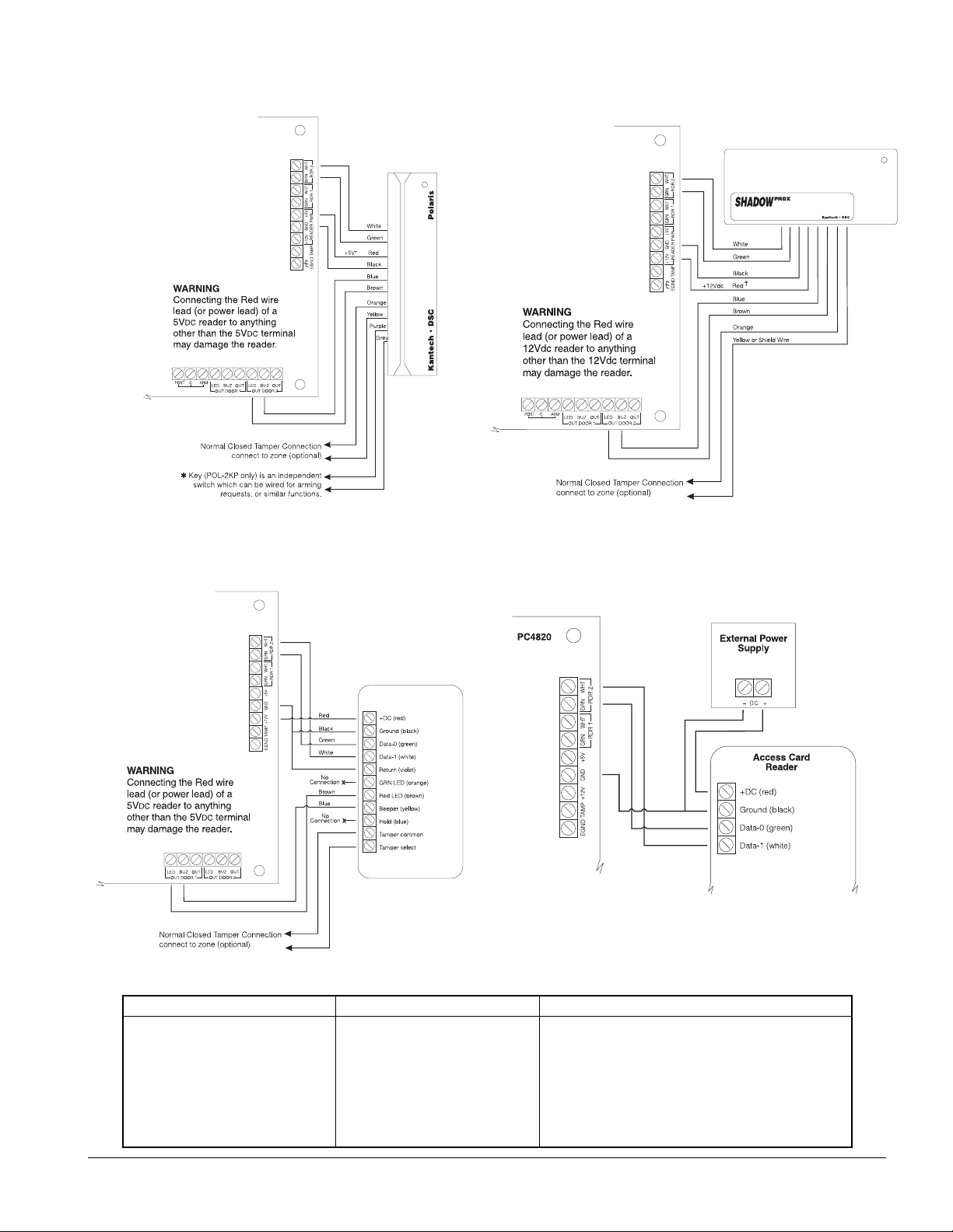
PC4820 Access Control Module Reader Connections
Polaris Readers (POL-1, POL-2, POL-2KP)
*
NOTE: Only use the +5V power supply when using
Polaris Readers.
Shadow Prox Readers
✝✝
✝
✝✝
NOTE: Only use the +12V power supply when using the
Shadow Prox Reader.
HID Readers Connecting External Power Supplies
Cabling Specifications
Component Maximum Wire Length Cable Description
Reader 5V 150m (500ft) 3 Pair, #18 AWG, stranded, overall shield
with extra drain conductor
Reader 12V 150m (500ft) 3 Pair, #22 AWG, stranded, overall shield
with extra drain conductor
Inputs (Door, REX, Post, Arm) 300m (1000ft) 2 pair, #22 AWG, twisted pairs
AC Transformer 8m (25ft) 1 pair, #18 AWG Ground 8m (25ft)
1 conductor, #18 AWG, Solid
5
 Loading...