

Page 1
Page 1
DSC PC 1832 series Alarm Dialler wiring & programming RDC_3049_E_TA
DSC PC1832 series Alarm Panel
Panel Dialler wiring
Panel Dialler programming
Background:
The PM45 & PM1048-3G (v3) communicator now has a terminal block for the connection of the female 611 fly lead (supplied).
If the Alarm Panel also has a terminal block for PSTN connection, we recommend you use your own cable between the Alarm
Panel dialler and PM45 & PM1048-3G (v3).
This type of installation negates the use of the female 611 fly lead, decreasing your installation time.
For four (4), six (6) and eight (8) pin RJ connectors, please refer to manufactures wiring diagram.
There are four minimum requirements from the Alarm panel for successful communication:
1) Must have an eight (8) digit primary phone. E.g. 12345678 or 55555555.
2) A four (4) digit account number.
3) Must be Contact ID format.
4) Must be set for tone (DTMF) dialling.
5) Optional is open / close reporting, must be enabled for Pocket Secure App.
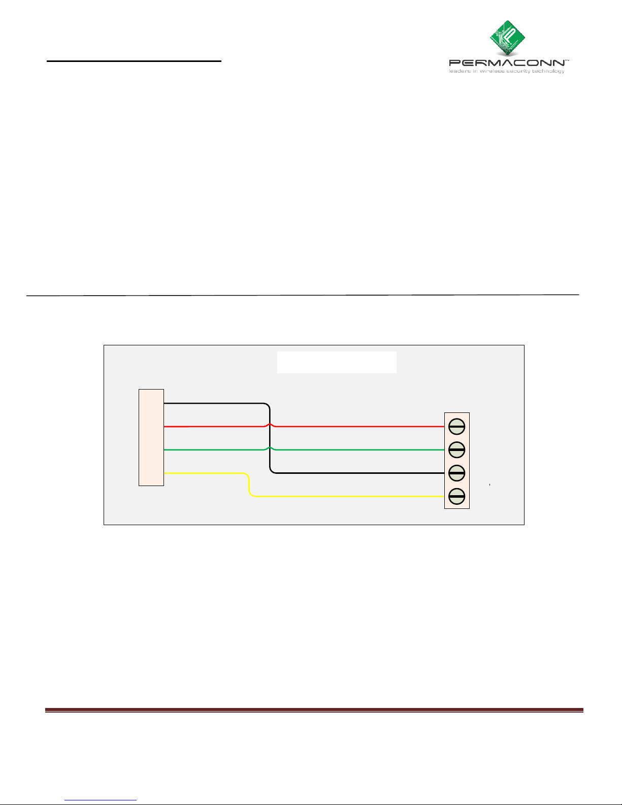
Dialler Lead wiring between Permaconn and DSC PC 1832 series Alarm Panel:
DSC PC550
Permaconn
R
R
T
T
1
1
Panel
black
red
green
yellow
red
green
black
yellow
Ring
R1
T1
Tip
DSC PC 1832 series
Page 2

Page 2
DSC PC 1832 series Alarm Dialler wiring & programming RDC_3049_E_TA
Programming the DSC PC1832 series Alarm Panel for dialler operation:
Description
Location
Notes
Enable Dialler
380
Option 1
0ff = Disable
On = Enable (Default)
First System Option Code
380
Option 3 = DTMF
0ff = DTMF (Default)
On = Pulse
Message format
Phone 1
350
03 = DTMF Contact ID
Enter 0 3 0 3
System Account
310
Enter A for a 0
A = *1
E.g. 2090
2 *1 9 *1 #
Partition 1 Account
311 E.g. 2091
2 *1 9 1 #
Partition 2 Account
312 E.g. 2092
2 *1 9 2 #
Partition 3 Account
314 E.g. 2093
2 *1 9 3 #
Partition 4 Account
315 E.g. 2090
2 *1 9 4 #
Phone number
301
Enter # End of number
E.g. Phone Number Entry
1-2-3-4-5-6-7-8-#
Opening / Closing Reports
Routing
367 – 368 = Part 1-2
Option 1 = Phone 1
Off = Disable
On = Enable (Default)
Arming Report
339 = Users 1-16
340 = Users 16-32
Enter = 0101010101010101
Enter = 0101010101010101
Disarming Report
342 = Users 1-16
343 = Users 16-32
Enter = 0101010101010101
Enter = 0101010101010101
Telephone Line Monitor
345
Swinger Shutdown
377
Refer to manual
 Loading...