


System Introduction
SECTION1
1.1 Specifications
Control Panel Specifications
Flexible Zone Configuration:
• Six fully programmable zones
• Seven Access Codes: five User, one Master and a
second Master code
• Normally Closed, Single EOL, Double EOL
• 23 Zone Types, 6 Programmable Zone Options
Audible Alarm Output:
• Supervised Bell Output (current limited at 3 amps), 12 V
• Steady or Pulsed Output
EEPROM Memory: Does not lose programming or
system status on complete AC and Battery failure
Programmable Outputs:
• Two Programmable Voltage Outputs, 20
programmable options
- One High Current (300 mA) PGM output on main
panel
- One Low Current (50 mA) PGM output on main
panel
Powerful 1.5 Amp Regulated Power Supply:
• 550 mA Auxiliary Supply, 12 V
• Positive Temperature Coefficient (PTC) components
replace fuses
• Supervision for loss of AC Power, Low Battery
• Internal Clock Locked to AC Power Frequency
Power Requirements:
• Transformer = 16.5 VAC, 40VA
• Battery = 12 volt 4 Ah minimum rechargeable sealed
lead acid
Remote Keypad Specifications:
• Three Different Keypads Available:
- PC5506T 6 Zone LED Keypad
- LCD5500T Alphanumeric Keypad
- PC1575RK 6 Zone LED Keypad
• The PC5506T and LCD5500T keypads have 5 Fully
Programmable Function Keys and Tampers
• Connect up to 8 Keypads
• Four Wire (Quad) Connection to KEYBUS
• Built in Piezoelectric Buzzer
Digital Communicator Specifications:
• Supports Major Formats including SIA, Scantronics 4-8-1
Slot and Contact ID
• Event Initiated Personal Paging
• Three Programmable Phone Numbers
• Two Account numbers
• DTMF and Pulse Dialing
• DPDT Line Seizure
• Anti-jam Feature
• Split Reporting of Selected Transmissions to Each
Telephone Number
DC
System Supervision Features
The PC1580 continuously monitors a number of possible
trouble conditions including:
• AC Power Failure
• Trouble by Zone
• Tamper by Zone
• Fire Trouble
• Telephone Line Trouble
• Failure to Communicate
DC
• Low Battery Condition
• Bell Output Trouble
• Module Fault (Supervisory or Tamper)
• Loss of Internal Clock
• AUX Power Supply Fault
False Alarm Prevention Features
• Audible Exit Delay
• Audible Exit Fault
• Communication Delay
• Urgency on Entry Delay
• Quick Exit
Additional Features
• Auto Arm at Specified Time
• Keypad Activated Alarm Output and Communicator
Test
• All modules connect to the system via a four wire
KEYBUS up to 1000’/330m from main panel
• Event Buffer can be printed using PC5400 RS232 Serial
Interface module
• Supports the ESCORT 5580 Voice Prompt Module with
Automation/Lighting Control
• An Event Buffer which records the past 100 events with
both the time and date at which they occured
• Uploading and Downloading capability
• Local Downloading capability with the use of the
PC-LINK Adaptor
• Time compensation feature
1.2 Additional Devices
1.2.1 Keypads
A maximum of eight keypads can be connected to the
control panel and can be any combination of the following
listed.
• PC5506T 6 zone LED keypad with function keys and
tamper
• LCD5500T LCD keypad with function keys and tamper
• PC1575RK 6 zone LED keypad
1.2.2 ESCORT5580 Module
There are many benefits to adding the ESCORT5580 module
to a security system. The ESCORT5580 module will turn any
touch tone phone in the world into a fully functional keypad.
Imagine the security a customer would feel if they had the
ability to arm, disarm and check status of their alarm system
while at the office or on vacation.
1
SYSTEMV INTRODUCTION
All touch tone phones in the home also become system
keypads. For example, at bedtime, the phone beside the bed
can be used to arm the system. The addition of the
ESCORT5580 may reduce the cost of the overall installation,
eliminating the need for additional keypads and the labour of
running wires.
The ESCORT5580 will also act
as a tutor for the system. By
using clear, easy to understand
sentences, the voice module
helps guide the user through
functions they may otherwise
find difficult to navigate. Programmable zone labels (up to
6 words each from our library of over 240 words) makes the
system even easier to use.
The module also has a built-in power line control interface
and can control up to 32 power line control devices for
lighting and temperature control, giving you the power to
add home automation in a very cost effective manner.
Devices can be activated individually, as a group, by
schedule or can be activated when an event occurs on the
system, such as an alarm.
These are just a few of the applications available with the
addition of the ESCORT5580 module. For more information,
please refer to the ESCORT5580 Installation Manual.
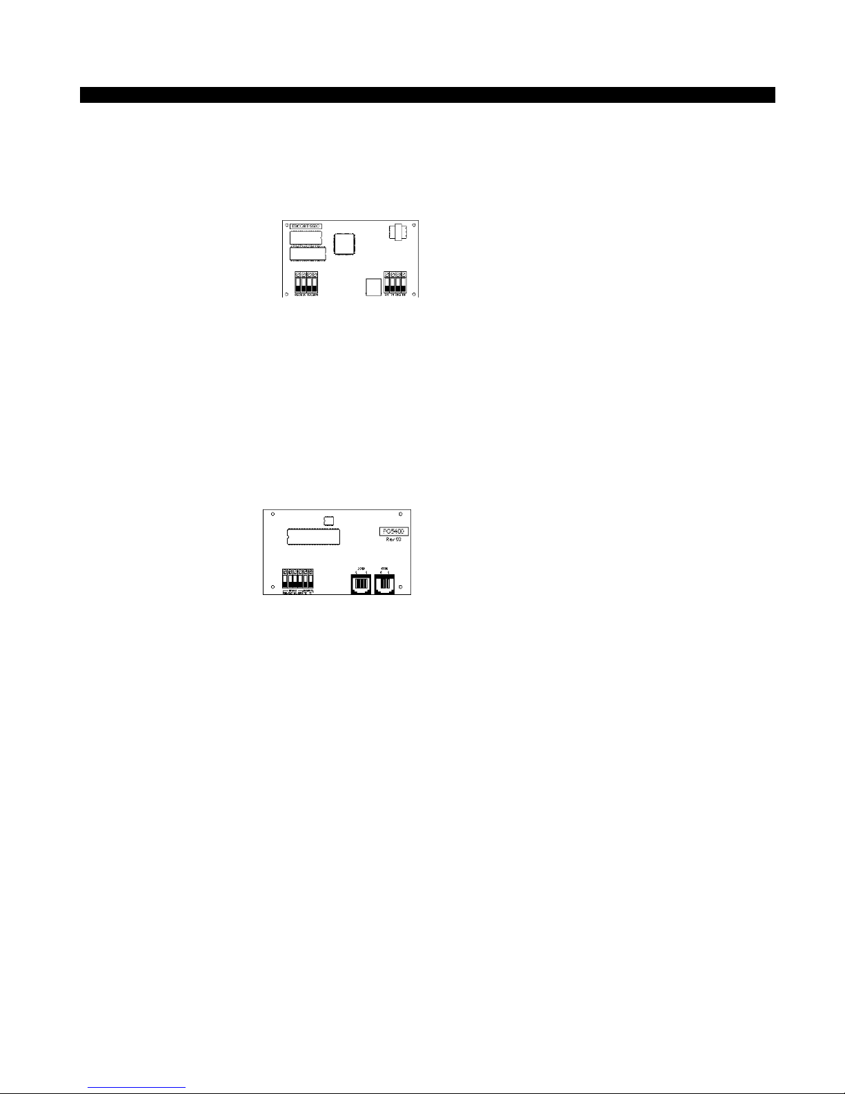
1.2.3 PC5400 Printer Module
This module will give you the
added advantage for the
commercial customers who
like the idea of a permanent
record of openings and
closing but are put off by the
additional monthly
monitoring charge. In addition, as reports are generated in
real-time, the customer will not have to wait for a monthly
report form the monitoring station.
The PC5400 Printer Module will allow the panel to print out
all events that occur on the system to any serial printer. The
printout will contain the time, date and the event that occurred
(see Section – 5.25 “On-site Printer”).
1.2.4 Downlook Video Transmission Module
The Downlook Still-Frame Video Transmission Module (DLM1/DLM-4) is the ideal solution for all business and residential
environments which require visual surveillance but where
the presence of on-site security personnel is impossible,
undesirable or unaffordable.
Downlook is the smart and inexpensive way to add visual
backup to your regular remote alarm signalling system,
meeting your demand for tighter security on a tight budget.
The added visual protection will reduce the incidence of
false alarms as well as surveillance costs, thus improving
the overall security protection.
For more information regarding the Downlook Video
Transmission Module, please consult the DLM-1/DLM-4
Installation Manuals.
1.2.5 Cabinets
Several different cabinets are available for the PC1580
modules. They are as follows:
PC5003C Cabinet
Control cabinet for the PC1580 main panel. Dimensions
288mm x 298mm x 78mm / 11.3” x 11.7” x 3” approximately.
PC5004C Cabinet
Cabinet to house the Escort5580 Module or the PC5400
Printer Module. Dimensions 229mm x 178mm x 65mm / 9”
x 7” x 2.6” approximately.
1.3 Out of the Box
Please verify that each of the following components is
included in your system:
• one PC1580 control cabinet
• one PC1580 control circuit board
• one keypad (LED keypad or LCD keypad)
• one Installation Manual including Programming
Worksheets
• one Instruction Manual for the end user
• one hardware pack consisting of:
-four plastic circuit board standoffs
-twelve 5600Ω (5.6K) resistors
-one 2200Ω (2.2K) resistors
-one 1000Ω (1K) resistor
-EGND Assembly
-one cabinet door plug
• 220V to16.5V AC transformer with fuseblock
• two yellow safety hazard warning labels to be applied by the
installer
Enclosed 240V AC Warning Labels
The Health & Safety (Signs and Signals) Regulations state
that warning signs must be displayed to warn people to be
careful to take precautions where a hazard exits.
These signs also comply to the Electricity at Work Regulation
1989 and BS5378.
The Regulations for Electrical Installation (16 Edition) Section
514-10 Warning Notice Voltage.
Every Item of Equipment or enclosure within which a voltage
exceeding 250 Volts exists, and where the presence of such
a voltage would not normally be expected, shall be so
arranged that before access is gained to a live part, a
warning of the maximum voltage present is clearly visible.
It is recommended that one of the enclosed warning stickers
be attached to the external area of the control panel housing
to give indication of voltage before access is gained to the
transformer area. The second enclosed warning sticker
should be placed on the front plate of the unswitched fuse
unit to give indication of mains connection within.
DSC accepts no responsibility for the non use of these
warning labels and can confirm that it is the responsibility of
the installation engineers to attach them to the required
devices during the installation process. The warning labels
are enclosed to be used in accordance with the Health and
Safety regulations and also the electricity at work act 1989.
2

Getting Started
SECTION2
The following Sections provide a thorough description of how to
wire and configure devices and zones.
2.1 Installation Steps
The following steps are provided to assist you with installing
the panel. We suggest that you read this section in its entirity
before you begin. Once you have an overall understanding of
the installation process, carefully work through each step.
Working in this manner will reduce the number of problems as
well as the amount of time required for a complete installation.
Step 1 Create a Layout
Draw a rough sketch of the building to get an idea of where
all alarm detection devices, keypads and other modules
are to be located.
Step 2 Mounting the Panel
Locate the panel in a dry area close to an unswitched AC
power source and the incoming telephone line. Before
attaching the cabinet to the wall, be sure to press the four
circuit board mounting studs into the cabinet from the back.
After you have attached the cabinet to the wall, stick the
provided DSC logo sticker on the front of the cabinet.
You must complete all wiring before applying AC or
connecting the battery to the panel.
Step 3 Wiring the KEYBUS (Section 2.3)
Wire the KEYBUS to each of the modules following the
guidelines provided in Section 2.3 of this manual.
Step 4 Zone Wiring (Section 2.8)
You must power down the control panel to complete all
zone wiring. Please refer to Section 2.8 when connecting
zones using normally closed loops, single EOL resistors,
double EOL resistors, Fire zones and Keyswitch Arming
zones.
Step 5 Complete Wiring (Section 2.2)
Complete all other wiring including bells or sirens, phone
line connections, and ground connections following the
guidelines provided in Section 2.2 (“Terminal
Descriptions”).
Step 6 Power up the Control
Once all zone and KEYBUS wiring is complete, power up
the control panel.
The panel will not power up on the battery connection alone.
Step 7 Keypad Assignment (Section 2.5)
In order for keypads to be properly supervised, each must
be assigned to a different slot. Please follow the guidelines
provided in Section 2.5 when assigning keypads.
Step 8 Supervision (Section 2.6)
The supervision of every module by the panel is
automatically enabled upon power up. Please verify that
all modules appear on the system according to the
instructions in Section 2.6.
Step 9 Programming the System (Sections 4 and 5)
Section 4 explains how to program the panel. Section 5
contains a complete description of the various
programmable features, which options are available and
how they function. The Programming Worksheets (pages
25-33) should be filled out completely before attempting
to program the system.
Step 10 Testing the System
The panel must be thoroughly tested to ensure that all
features and functions are operating as programmed.
2.2 Terminal Descriptions
AC Terminals – AC (50Hz)
The panel requires a 16.5 volt, 40 VA transformer. Connect
the transformer to an unswitched AC source and connect
the transformer to these terminals.
Do not connect the transformer until all other wiring
is complete.
The panel must have a power line frequency of
50Hz.
Battery Connection
A 12V 4Ah rechargable gel-cell battery is used as a back up
source of power in the event of an AC power failure. The
battery also provides additional current when the panel’s
demands exceed the power output of the transformer, such
as when the panel is in alarm.
Do not connect the battery until all other wiring is
complete.
Connect the RED battery lead to the positive battery terminal;
connect the BLACK lead to negative.
Auxiliary Power Terminals – AUX+ and AUX-
These terminals provide up to 550 mA of additional current
DC for devices requiring power. Connect the positive
at 12 V
side of any device requiring power to the AUX+ terminal, the
negative side to AUX- (ground). The AUX output is protected.
This means that if too much current is drawn from these
terminals (such as a wiring short), the panel will temporarily
shut off the output until the problem is corrected.
Bell Output Terminals – BELL+ and BELL- (Section 3.4)
These terminals provide up to 700 mA of continuous current
at 12 V
DC for powering bells, sirens, strobes or other warning-
type equipment. Connect the positive side of any alarm
warning device to BELL+, the negative side to BELL–.
Please note that the Bell output is protected: if too much
current is drawn from these terminals (such as a wiring
short), the Bell fuse will open. Three Amps can be drawn for
short periods only.
The Bell output is supervised. If no alarm warning devices
are in use, connect a 1000 ohm resistor across BELL+ and
BELL– to prevent the panel from displaying a trouble
condition. For more information, please refer to Section 3.4
✱] [2] Trouble Display”).
(“[
The bell is programmed by default to terminate after four
minutes. The Bell Cutoff time can be adjusted in
programming section [02] (“System Times”).
KEYBUS Terminals – AUX+, AUX-, YEL, GRN (Section 2.3)
The KEYBUS is used by the panel to communicate with
modules and vice versa. Each module has four KEYBUS
terminals that must be connected to the four KEYBUS
terminals on the panel. For more information, see Section
2.3 (“KEYBUS Operation and Wiring”).
3
G E T T I N G S T A R T E D
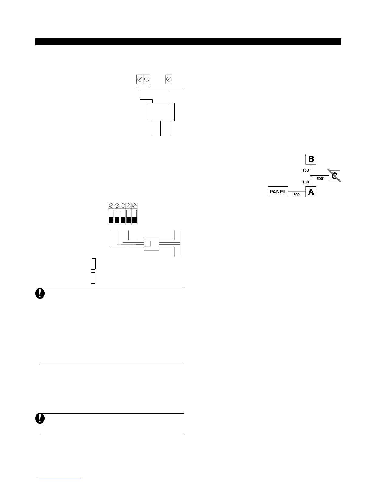
Programmable Outputs – PGM1 and PGM2
Each PGM output is designed so
that when activated by the panel, the
terminal will switch to ground.
PGM2 can sink up to 50 mA of current
to activate LEDs or a small buzzer.
Connect the positive side of the LED
+AUX PGM1
RED
or buzzer to AUX+, the negative side
to PGM2. If more than 50 mA of
current are required, a relay must be
used. Please study PGM wiring in
the accompanying diagram.
PGM1 is a high current output which
COM NC
operates similar to PGM2. PGM1 is
used for high current output (300mA).
Zone Input Terminals – Z1 to Z6
Each detection device must be connected to a zone on the
control panel. We suggest that one detection device be
connected to each zone; wiring multiple detection devices
to a single zone, however, is possible. For zone wiring
specifics, please see Section 2.8 (“Zone Wiring”).
Telephone Connection Terminals – TIP, RING, T-1, R-1
If a telephone line is
required for central
station communication or
downloading, connect an
RJ-31X telephone jack in
the following manner:
• TIP - Green Wire incoming line from
RING TIP R-1
RED
GRN
EGND
T-1
GRY
BRN
RJ31X
TELEPHONE
PLUG
• RING - Red Wire telephone company
• R-1 - Grey Wire outgoing line to
• T-1 - Brown Wire house telephone(s)
Please ensure that all plugs and jacks meet the
correct dimension, tolerance and metallic plating
requirements.
For proper operation, no other telephone equipment
should be connected between the control panel and
the telephone company facilities.
Do not connect the alarm panel communicator to
telephone lines intended for use with a fax machine.
These lines may incorporate a voice filter which
disconnects the line if anything other than fax
signals are detected, resulting in incomplete
transmissions.
2.3 KEYBUS Operation and Wiring
The KEYBUS is used by the panel to communicate with all
connected modules and vice versa. The red (AUX+) and
black (AUX-) terminals are used to provide power, while the
yellow (YEL) and green (GRN) terminals are clock and data
respectively.
The four KEYBUS terminals of the panel must be
connected to the four KEYBUS terminals or wires of
all modules.
(ANY OUTPUT
TERMINAL)
BLK
DSC
RM-1
YEL
WHT
GRN
NO
PREMISE
TELEPHONE
TELEPHONE
The following restrictions apply to KEYBUS wiring:
• KEYBUS should be run in minimum 22 gauge quad
(0.5mm); two pair twist is preferred.
• The modules should be home run to the panel but can
be connected in series or T-tapped .
• Any module can be connected anywhere along the
KEYBUS. You do not need to run a separate KEYBUS
wire for keypads, etc.
• No module can be more than 1,000'/330m (in wire
length) from the panel.
• Shielded wire should not be used unless wires are run
in an area that presents excessive RF noise or other
such interference.
Example of KEYBUS Wiring
NOTE:
Module (A) is correctly
wired within 1,000'/330m
of wire from the panel.
Module (B) is correctly
wired within 1,000'/330m
of wire from the panel.
Module (C) is NOT wired
correctly as it is further
than 1,000'/330m from the
panel, in wire distance.
TO
2.4 Current Ratings – Modules and
Accessories
In order for the PC1580 system to operate properly, the
power output capabilities of the main control and the
expansion devices must not be exceeded. Use the data
TO
presented below to ensure that no part of the system is
overloaded and cannot function properly.
PC1580 (12 V
DC)
VAUX: 550 mA. Includes one keypad. Subtract for each
additional keypad, expansion module and accessory connected to VAUX or KEYBUS.
BELL: 700 mA. Continuous Rating. 3.0 A. Short Term.
Available only with stand-by battery connected.
PC1580 Device Ratings (@ 12 V
• LCD5500T Keypad: 50 mA
• PC5400 Serial Module: 65 mA
• PC5506T Keypad: 45 mA
• PC1575RK Keypad: 50 mA
• DLM-4: 160 mA standing / 180 mA transmitter
• Escort: 65 mA standing / 130 mA on-line
Other Devices
Please read the manufacturer’s literature carefully to
determine the maximum current requirements for each
device—during activation or alarm—and include the proper
values for loading calculations. Connected devices must
not exceed system capabilities during any possible
operational mode.
2.5 Keypad Assignment
There are eight available slots for keypads. LED keypads by
default are always assigned to slot 1; the LCD5500T is
always assigned to slot 8. Whereas the PC1575 LED keypad
must always be assigned to slot 1, the PC5506T and
DC)
4
G E T T I N G S T A R T E D
DOUBLE EOL CIRCUIT
1 NORMALLY CLOSED
LCD5500T keypads can each be assigned to a different slot
(1 to 8). Keypad enrollment is required since the panel must
know which slots are occupied in order to generate a fault
when a supervisory is not present.
How to Assign Keypads
Each keypad must be assigned one at a time. After
assigning all keypads, a supervisory reset should
be performed.
To assign a keypad to a slot, enter the following:
1. Enter Installer’s Programming.
2. Press [00] for Keypad Programming.
3. Press [0] for Slot Assignment.
4. Enter a two digit number (11-18) to specify which
supervisory slot the keypad will occupy.
Press the [#] key twice to exit programming. Continue this
procedure at each keypad until they have all been assigned
to the correct slot.
When using more than one LCD keypad, be sure
that only one is assigned to slot number 8.
2.6 Supervision
By default, all modules are supervised upon installation.
Supervision is enabled at all times so that the panel can
indicate a trouble if a module is removed from the system.
A connected module which does not show as being present
will appear as a trouble condition and the Trouble light on the
keypad will turn ON. This condition may be due to one or more
of the following reasons:
• the module is not connected to the KEYBUS
• there is a KEYBUS wiring problem
• the module is more than 1,000'/330m from the panel
• the module does not have enough power
For more information regarding module supervision troubles,
please refer to Section 3.4 (“[
✱] [2] Trouble Conditions”).
Modules will not be automatically supervised if
connected while in installers mode.
2.7 Removing Modules
The panel must be instructed to no longer supervise a module
being removed from the system. To remove the module,
disconnect it from the KEYBUS and reset the supervision
field by entering [92] in the installer’s programming. The
panel will be reset to recognize and supervise all existing
modules on the system.
2.8 Zone Wiring
For a complete description of the operation of all zone types,
please refer to Section 5.2 (“Zone Definitions”).
There are several different ways in which zones may be
wired, depending on which programming options have
been selected. Please refer to the following diagrams to
study each type of individually supervised zone wiring.
Any zone defined as Fire will automatically require a
single End of Line (EOL) resistor regardless of which
type of zone wiring supervision is selected. (See Section
5.2 “Zone Definitions.”) Reconfiguring the zone supervision from a non-default setting—from DEOL to EOL or
from NC to DEOL—may disable zones 1-6 while open or
in trouble. To prevent this situation, the system should be
powered down completely and powered up again.
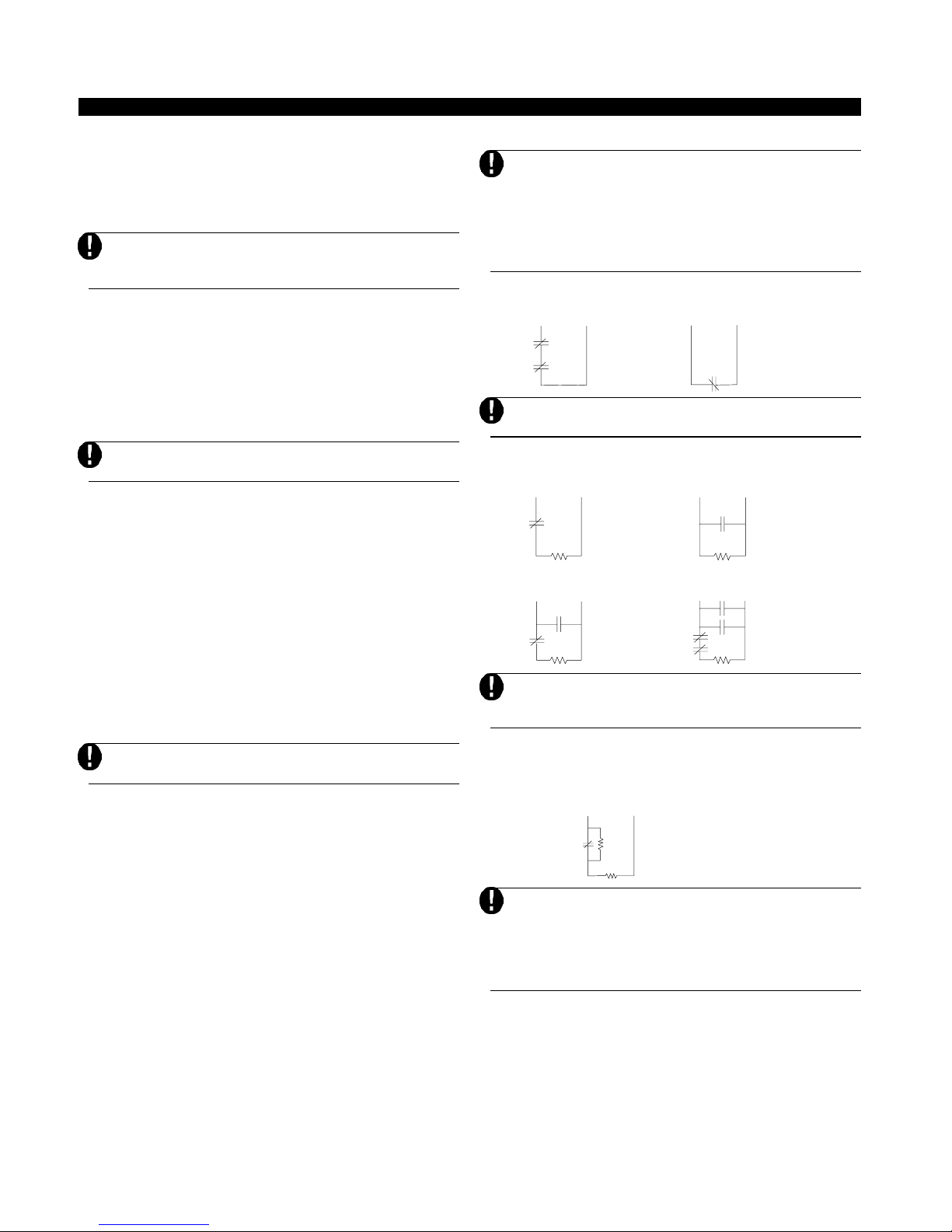
2.8.1 Normally Closed (NC) Loops
ANY Z
TERMINAL
ANY COM
TERMINAL
2 NORMALLY CLOSED
CONTACTS WITH
NO END OF LINE
RESISTOR
ANY Z
TERMINAL
ANY COM
TERMINAL
NORMALLY CLOSED
CONTACT WITH
NO END OF LINE
RESISTOR
This option should only be selected if Normally Closed
(NC) detection devices or contacts are being used.
2.8.2 Single End Of Line (EOL) Resistors (5600W)
ANY Z
TERMINAL
ANY Z
TERMINAL
ANY COM
TERMINAL
NORMALLY
CLOSED
CONTACT WITH
END OF LINE
RESISTOR
ANY COM
TERMINAL
1 NORMALLY OPEN
CONTACT AND
1 NORMALLY CLOSED
CONTACT WITH
END OF LINE
RESISTOR
ANY Z
TERMINAL
ANY Z
TERMINAL
ANY COM
TERMINAL
NORMALLY OPEN
CONTACTS WITH
END OF LINE
RESISTOR
ANY COM
TERMINAL
2 NORMALLY OPEN
CONTACTS AND
2 NORMALLY CLOSED
CONTACTS WITH
END OF LINE
RESISTOR
This option should be selected if either Normally
Closed (NC) or Normally Open (NO) detection
devices or contacts are being used.
2.8.3 Double End of Line (DEOL) Resistors
Double End of Line resistors allow the panel to determine if
the zone is in alarm, tampered or faulted.
ANY Z
ANY COM
TERMINAL
TERMINAL
ALARM
CONTACT
CONTACT WITH
5600 END OF LINE
Ω
RESISTORS
This option can only be selected if Normally Closed
(NC) detection devices or contacts are being used
(ie: Do not use DEOL resistors for Fire zones.
Only one NC contact can be connected to each
zone. Multiple detection devices or contacts on a
single loop is not allowed.
The following chart shows zone status under certain
conditions:
• Loop Resistance ................................ Loop Status
• 0Ω (shorted wire, loop shorted) ....... Fault
• 5600Ω (contact closed) .................... Secure
• Infinite (broken wire, loop open)....... Tamper
• 11200Ω (contact open) ..................... Violated
5
G E T T I N G S T A R T E D
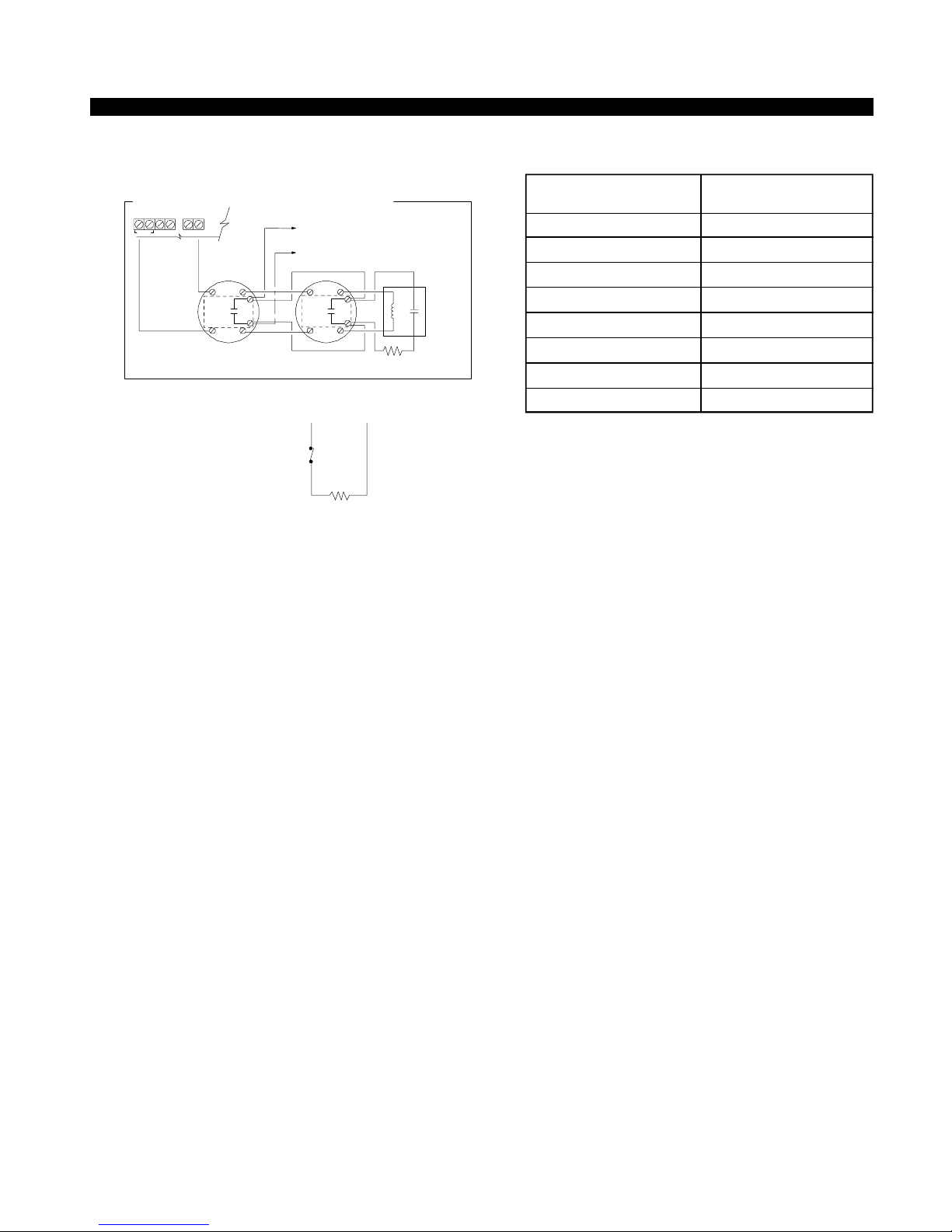
2.8.4 Fire Zone Wiring — Four-Wire Smoke Detectors
All fire zones must be wired according to the following
diagram:
4-WIRE SMOKE DETECTOR CONNECTION WITH RESET
TO ZONE "Z"
AUX++ BELL -1 PG M 2
ALARM
CONTACT
ININOUT
OUT
TERMINAL
PROGRAMMED
FOR "FIRE"
TO ANY "COM"
TERMINAL
OUT
IN
ALARM
CONTACT
OUT
IN
●
MINIMUM 18 AWG WIRING IS REQUIR
FOR RESIDENTIAL FIRE ALARM SYST
BLK
RED
5600
Ω
END OF LINE RESISTOR
(EOLR-2)
2.8.5 Keyswitch Zone Wiring
If PGM2 has been
PGM2
AUX+
programmed for keyswitch
operation (momentary or
maintained), the
keyswitches must be wired
according to this diagram:
NORMALLY CLOSED
CONTACT WITH
5600 END OF LINE
Ω
RESISTOR
WHT
POWER
SUPERVISORY
RELAY
(DSC RM-1)
GRN
2.9 Wiring Gauge Conversion Table
North American Gauges Metric Wire Diameter
(AWG) (mm)
AWG-14 1.62mm
AWG-16 1.29mm
AWG-18 1.02mm
AWG-19 0.91mm
AWG-20 0.81mm
AWG-21 0.72mm
AWG-22 0.64mm
AWG-24 0.50mm
6

Keypad Commands
SECTION3
The PC1580 alarm panel can be accessed, controlled and
completely programmed via any keypad on the system. The
LED keypad uses function and zone indicator lights to represent alarm functions and status. The LCD keypad provides a
written description on the liquid crystal display and uses
function indicator lights to communicate alarm status to the
user.
The following sections describe how to arm and disarm the
system from each type of keypad, and how to perform other
keypad functions.
3.1 Arming and Disarming
The system cannot be armed unless the Ready light is ON.
In order for the system to be in the Ready state, all protected
doors and windows must be secured and all movement in
areas covered by motion detectors must cease. When the
Ready light is ON, enter any valid access code. As each
digit is pressed, the keypad will beep. If the correct code is
entered when the system is not in the Ready state, the panel
will sound six quick beeps followed by a long two-second
beep to indicate that the system is not secured.
If an incorrect code is entered, the keypad will emit a steady
two second beep to indicate the invalid access code. When
the correct code is entered and the system is Ready, the
panel will emit six short beeps and the Armed light will turn
ON. Exit the premises through the designated entry/exit
door. For other methods of arming, please refer to section
✱] [0] Quick Exit” and “[✱] [9] Arming Without Entry
3.4 (“[
Delay”) and section 3.5 (“Function Keys”).
In an attempt to prevent false alarms, the Audible Exit Fault is
designed to notify the user of an improper exit when they arm
their system. If a non force-arming Delay 1 or Delay 2 type zone
is left open at the end of the exit delay, the entry delay will begin
immediately and the bell or siren will sound a steady alarm for
the entry delay period. At the end of the entry delay period, if
the system has not been disarmed it will go into alarm.
When you enter the premises through a designated entry/
exit door while the system is armed, the keypad will emit a
steady beep to remind you to disarm the system. Enter a
valid access code from any keypad to disarm the system. If
an error is made, press the [#] key and enter the code again.
When a correct code is entered, the Armed light will turn
OFF and the keypad will stop beeping. During the last 10
seconds of entry delay, the panel will pulse the keypad
beeper ON and OFF rapidly to warn you that the entry delay
is about to expire.
If an alarm occurred while the panel was armed, the Memory
light and the zone indicator lights corresponding to the
zones which went into the alarm will be flashing. Press the
[#] key to return the keypad to the Ready state.
3.2 Auto Bypass – Stay Arming
Stay arming allows the user to arm the system without
leaving the premises. All interior zones can be programmed
to be bypassed during Stay arming so that the user does not
have to bypass interior zones manually.
When the system is armed using a valid user code, if any
zones on the system have been programmed as Stay/Away
zones, the Bypass light will turn ON. The panel will then
monitor all zones programmed as Delay 1 and Delay 2
zones, such as designated entry/exit doors. If no delay type
zone is violated by the end of the exit delay, the panel will
bypass all Stay/Away type zones. The Bypass light will
remain ON to inform the user that the interior protection has
been automatically bypassed by the panel. If a delay zone
is violated during the exit delay, the Stay/Away zones will be
active after the exit delay expires.
The user can add the Stay/Away zones back into the system
at any time by entering the [
section 3.4 “[
Zones”).
Stay arming can also be initiated by pressing and holding
the Stay function key for two seconds on the PC5506T and
LCD5500T keypads, if programmed by the installer. For
more information regarding Stay arming, please see section
3.5 (“Function Keys”).
✱] [1] Bypassing and Reactivating Stay/Away
✱] [1] keypad command (see
3.3 Automatic Arming
The system can be programmed to Auto-Arm at a specific
time every day if it is in the disarmed condition.
In order for the Auto-Arm function to work properly, the
correct Time of Day must be programmed. To program the
clock and Auto-Arm times, see Section 3.4 ([
Functions)
When the system’s internal clock matches the Auto-Arm
Time, the panel will check the system status. If armed, the
panel will do nothing until the next day at the Auto-Arm
Time, when it will check the system again. If disarmed, the
panel will sound the buzzer of all keypads for one minute. If
a valid User Code is entered, the Auto-Arming will be
aborted.
If no code is entered, the panel will Auto-Arm. If a zone is
violated, the panel will transmit a Partial Closing Reporting
Code – if programmed – to indicate to the central station that
the system is not secure. If the zone is restored, the panel
will add the zone back into the system (see Section 5.7
“Communicator – Reporting Codes”).
3.4 [✱] Commands
The [✱] key commands provide an easy way for the user to
access basic system programming – such as entering user
codes or bypassing zones. The user can also use the [
commands to check on the system’s status, including viewing
trouble conditions and displaying the event buffer on the LCD
keypad.
The [
✱] key commands can be performed from both LCD
and LED keypads. The LED keypad uses the zone indicator
lights to display command information. The LCD display
provides written information, guiding the user through each
command. The commands in this section are explained as
viewed from an LED keypad. When using an LCD keypad,
use the arrow keys (< >) to scroll through information
provided. Otherwise, the functions remain the same for both
keypad types.
[✱] [1] Bypassing and Reactivating Stay/
Away Zones
The [✱] [1] keypad command can be used to bypass
individual zones. A bypassed zone will not cause an alarm.
The user can bypass zones to gain access to an area while
arming the rest of the system or to override a defective
zone—due to a bad contact or damaged wiring—until
service can be provided.
✱] [6] User
✱] key
7

KEYPADV COMMANDS
If the Code Required for Bypass option is enabled, only
user codes with the Bypass attribute enabled will be able to
bypass zones (see section 5.1 “Programming Security
Codes”).
If the Bypass Status Displayed While Armed is chosen,
the Bypass light will be ON while the system is armed to
indicate any bypassed zones (see section 5.15 “Arming /
Disarming Options”).
Zones can only be bypassed when the system is
disarmed.
To bypass a zone:
1. Enter [
✱] [1] (and an access code, if required).
2. The keypad will flash the Bypass light and the zone
indicator lights corresponding to any zones already
bypassed will turn ON.
3. Enter the number corresponding to the zone you wish
to bypass. The corresponding zone indicator light will
turn ON.
4. Press [#] to exit the function.
All zones whose indicator lights are ON when the [#]
key is pressed will be bypassed. The Bypass light will
turn ON, indicating that zones are bypassed.
To reactivate a bypassed zone:
1. Enter [
✱] [1] (and an access code if required).
2. The keypad will flash the Bypass light. The zone
indicator lights corresponding to any zones already
bypassed will turn ON.
3. Enter the number corresponding to the bypassed zone
you wish to reactivate. The corresponding zone
indicator light will turn OFF.
4. Press [#] to exit the function.
All zones whose indicator lights are ON when the [#]
key is pressed will be bypassed. If no zone indicator
lights were ON, the Bypass light will be OFF and no
zones will be bypassed.
When the system is disarmed, all manually-bypassed zones will be unbypassed.
Reactivate Interior
If the system is armed in the Stay mode, the [
✱] [1] command
can be used to reactivate the Stay/Away zones.
Reactive Stay/Away cannot be used with an alarm in
memory.
Please ensure all force-armed zones are restored
before reactivating the Stay/Away zones (See
Section 5.3 “Zone Attributes”).
[✱] [2] Trouble Display
The panel constantly monitors itself for several different
trouble conditions. If a trouble condition is present, the
Trouble light will be ON and the keypad will beep twice
every 10 seconds. The trouble beep can be silenced by
pressing any key on any keypad.
To view trouble conditions from an LED keypad:
1. Press [✱] [2].
2. The keypad will flash the Trouble light. The zone indicator
lights corresponding to the present trouble conditions
will be ON.
When using an LCD keypad, the trouble conditions will be
listed on the display; the user must simply use the arrow (< >)
keys to scroll through the list of present trouble conditions.
The various troubles are described below:
Trouble [1] – Service Required
If zone indicator light [1] is ON, a “service required” trouble
is present. Press [1] to determine the specific trouble. The
following is a list of “service required” trouble conditions:
• Light [1] – Low Battery
The main panel backup battery is low. The trouble will
be generated if the battery drops below 11.5 volts
under load and will be restored when the battery
charges to over 12.5 volts.
• Light [2] – Bell Circuit Trouble
The panel will indicate this trouble if the Bell fuse is
blown or if the panel senses an open condition on the
bell circuit (see Section 5.12 “Siren Supervision”).
• Light [3] – General System Trouble
This trouble will be present if the printer connected to
the PC5400 Printer module has a fault and is off-line, or
if the ESCORT module does not detect the Power Line
Interface Module.
• Light [4] – General System Tamper
This trouble will be indicated if any peripheral module
tamper is detected.
• Light [5] – General System Supervisory
This trouble will be indicated if the panel loses
communication with any module connected to the
KEYBUS (see Section 2.6 “Supervision”). The event
buffer will log a detailed description of the event.
Trouble [2] – AC Failure
This trouble indicates that AC power is no longer being
supplied to the control unit. The reporting codes in sections
[43] and [44] can be programmed to communicate a power
failure to the monitoring station. To avoid reporting short power
failures to the monitoring station, an AC Failure
Communication Delay from 000-255 minutes can be
programmed in section [62].
Trouble [3] – Communication Troubles
There are two types of telephone line trouble conditions. Press
[3] to display which type of trouble is present:
• [1] – Telephone Line Monitoring Trouble (TLM)
The telephone connection to the control unit is monitored
every 10 seconds. If the voltage drops below one to three
volts for the number of consecutive checks programmed
in section [62], a telephone line trouble is generated.
• [2] – Failure to Communicate (FTC)
This trouble will be generated if the communicator fails
to communicate with any of the programmed telephone
numbers. If a later attempt is successful, the FTC
reporting code(s) programmed in section [45] will be
transmitted along with the unreported events from an
earlier unsuccessful communication.
8

KEYPADV COMMANDS
Trouble [4] – Zone Fault (including Fire Zone)
This trouble will be generated if any zone on the system is
experiencing trouble, meaning that a zone could not provide
an alarm to the panel if required to do so. When a zone fault
trouble condition occurs, the keypad(s) on the system will
start to beep.
Press [4] while in Trouble mode to view the affected zones.
A Fire zone trouble will be generated and displayed
in the armed state. A Fire zone trouble will also
restart the trouble beeps from all keypads.
Trouble [5] – Zone Tamper
This trouble is only generated by zones configured for
Double End Of Line Resistor Supervision when a tamper
condition is present. When a tamper condition occurs, the
keypad(s) will start to beep. Press [5] while in the Trouble
mode to view the affected zones.
Trouble [6] – Loss of System Time
This trouble occurs when the control unit is powered up and
the internal clock has not been set. Setting the time with User
Function [
✱][6][Master Code][1] will clear this trouble.
[✱] [3] Alarm Memory
The ‘Memory’ light will be on if any alarm occurred during the
last armed period or – in the case of 24 hour zones – if an
alarm occurred while the panel was disarmed.
To view alarm memory:
Press [✱] [3]. The keypad will flash the Memory light and the
zone indicator lights corresponding to the alarm or tamper
conditions which occurred during or since the last armed
period. To clear the Memory light, arm and disarm the
system.
[✱] [4] Door Chime On/Off
The door chime feature is used to sound a tone from the
keypad whenever a zone programmed as a chime zone is
activated (see Section 5.3 – “Zone Attributes”). If the door
chime feature is enabled, the keypad will emit five short
beeps whenever a chime zone is activated. Designated
entry/exit doors are often defined as chime zones; when the
feature is enabled, the keypads will sound when an entry/exit
door is opened.
To turn Door Chime ON or OFF:
1. Press [
✱] [4].
2. The keypad will emit three short beeps if the Door
Chime feature is enabled and one long beep when
disabled.
The function can also be peformed by pressing and holding
the Chime function key for two seconds on any PC5506T or
LCD5500T keypad.
[✱] [5] Programming Access Codes
There are 6 access codes available to the user. They are as
follows:
Access code (1)..............................One Master Code
Access codes (2) to (6)..................Five User Codes
All access codes have the ability to arm or disarm the
system and can activate the PGM Outputs using the [
[1] [Access Code] and [
✱] [7] [2] commands.
✱] [7]
Master Code – Access Code (1)
By default, the Master Code is enabled to perform any
keypad function. This code can be used to program all User
Codes. If the Master Code Not Changeable option is
enabled, the Master Code can only be changed by the
Installer.
User Codes – Access Codes (2) to (6)
User codes can arm and disarm the system. By selecting
the No Code Required for Bypassing option, each user
can also have the ability to bypass zones without entering
an access code.
Duress Code – Access Code (6)
If the Sixth Code is Duress Code option is enabled, the
sixth code can be programmed by the user as a Duress
Code which will send a Duress reporting code to the central
station when entered.
For more information regarding access code options, please
see Section 5.1 – “Programming Security Codes.”
How to program User Codes:
1. Enter [
✱] [5] [Master Code]. The keypad will flash the
Program light. The zone indicator lights corresponding to
access codes already programmed will turn ON.
2. Enter the number corresponding to the code you wish to
program. The corresponding zone light will flash.
3. Enter a 4 digit code. The zone light will turn ON.
4. Continue from step 2 until all codes are programmed.
Once the process is complete, press the [#] key to return
to the Ready state.
Do not press [✱] or [#] when programming the 4 digit
code.
How to erase an Access Code:
✱] [5] [Master Code], select the code to be erased
Enter [
and press [
✱].
[✱] [6] User Functions
This keypad command can be used to program several
different functions. The programmable items are listed and
described below.
To program User Functions:
1. Press [
2.Press the number [0] to [9] for the item to be
• [1] – Time and Date
• [2] – Auto-Arm Enable/Disable
✱] [6] [Master Code]. The Program light will
flash.
programmed.
The time and date must be accurate for the Auto-Arm
or Test Transmission functions to work properly and for
the event buffer to time and date stamp all events.
- Enter the time (hour and minute) using military format
[HH MM] from 00:00 to 23:59.
- Enter the date by month, day and year [MM DD YY].
Auto-Arming will not work unless it is enabled for the
system. To enable or disable auto-arming, press [2]. The
keypad will emit three short beeps if the Auto-Arm feature
is enabled and one long beep when disabled. For more
information, see Section 3.3 – “Auto-Arming”.
9

KEYPADV COMMANDS
• [3] – Auto-Arm Time
The system can be programmed to Auto-Arm at a
certain time. When programming the auto-arming time,
enter the time (hour and minute) using military format
[HH MM]. For more information, see Section 3.3 –
“Auto-Arming”.
• [4] – System Test
When [4] is pressed the panel will test the bell output,
keypad lights and the communicator for two seconds.
The panel will also send a System Test Reporting
code, if programmed (see Section 5.7 – “Communicator – Reporting Codes”).
• [5] – Enable DLS (Downloading)
When [5] is pressed, the panel will enable the downloading option for one hour. During this time the panel
will answer incoming downloading calls (see Section
5.9 “Downloading”).
• [6] – User Initiated Call-Up
When [6] is pressed, the panel will initiate call-out to
the downloading computer.
• [7] – Last Code to Disarm and Arm
Pressing [7] will display the last code to disarm the
system. Then, pressing [9] will display the last code to
arm the system.
• [0] – Walk Test Enable / Disable
The Installer Walk Test can be used to verify that each
zone of the panel is functioning properly. Any zone
violated during a walk test will cause the panel to
activate the Bell Output for two seconds, log the event
to the Event Buffer and communicate the alarm to
central station. Do not tamper or fault zones while in
walk test. You can exit walk test with zones open. You
can cancel walk test by arming with all zones restored.
Additional Features using the LCD Keypad
Additional features, including access to the Event Buffer, are
available using the LCD keypad. Use the arrow keys (< >) to
scroll through the [
✱] [6] menu and press the [✱] key to select
the following commands:
Viewing the Event Buffer from an LCD Keypad
Select “View Event Buffer” from the [
✱] [6] menu. The
keypad will display the event, event number, time and date
along with the zone number and user code, if applicable.
Press [
✱] to toggle between this information and the event
itself. Use the arrow keys (<>) to scroll through the events
in the buffer. When you have finished viewing the Event
Buffer, press the [#] key to exit.
Brightness Control
The LCD keypad will allow you to select from 10 different
backlighting levels. Use the arrow keys (< >) to scroll to the
desired backlighting level and press the [#] key to exit.
Contrast Control
The LCD keypad will allow you to select from 10 different
display contrast levels. Use the arrow keys (< >) to scroll to
the desired contrast level and press the [#] key to exit.
Keypad Beeper Control
The LCD keypad will allow you to select from 21 different
keypad beeper tones. Use the arrow keys (< >) to scroll to
the desired keypad beeper level and press the [#] key to
exit. This featured can be accessed on LED keypads by
holding the [
✱] key.
[✱] [7] Output Functions
There are two output functions available to the user: Utility
Output and Sensor Reset.
To activate Utility Output:
✱] [7] [1][Access Code].
Press [
The panel will activate all PGM Outputs programmed as
utility outputs for five seconds (see Section 5.10 – “PGM
Outputs”).
To activate Sensor Reset:
✱] [7] [2].
Press [
The panel will activate all PGM Outputs programmed as
Sensor Reset for five seconds.
This function can also be performed by pressing and
holding the Reset function key for two seconds on any
PC5506T or LCD5500T keypad.
[✱] [8] Installer’s Programming
Enter [✱] [8] followed by the Installer’s Code to enter this
function. Installer’s Programming is outlined in detail in
Sections 4 and 5 of this manual.
[✱] [9] Arming Without Entry Delay
When the system is armed with the [✱] [9] command, the
panel will cancel the entry delay. Once the exit delay has
expired, Delay 1 and Delay 2 type zones will be instant and
Stay/Away zones will be bypassed (see Section 5.2 – “Zone
Definitions”). A valid access code must be entered after
pressing [
✱] [9].
[✱] [0] Quick Arm
If the Quick Arm option is enabled, the panel can be armed
without a user code by entering [
✱] [0] (See Section 5.15
“Arming / Disarming Options”).
Quick Arm cannot be used to cancel Auto Arm.
Quick Exit
The Quick Exit function, if enabled, will allow someone to
leave an armed premises through a Delay type zone without
having to disarm and rearm the system (See Section 5.15
“Arming / Disarming Options”).
When [
✱] [0] is entered, the panel will provide a two minute
window for the user to exit the premises. During this time, the
panel will ignore only one activation of a Delay zone. When
the Delay zone is secured, the panel will end the two minute
quick exit delay.
If a second Delay zone is tripped or if the zone is not restored
after two minutes, the panel will begin the entry delay.
If the Exit Delay is in progress, performing a Quick
Exit will not extend the Exit Delay.
3.5 Function Keys
The function keys only appear on the PC5506T and
LCD5500T keypads
There are five function keys on the PC5506T and LCD5500T
keypads located to the right of the number pad labelled
Stay, Away, Chime, Reset and Exit. Each of these keys are
programmed by default to perform one of the functions
10

KEYPADV COMMANDS
[06] – [
described below. A function is activated by pressing and
holding the appropriate key for two seconds.
“Stay” – Stay Arm
Pressing this key will arm the system in the Stay mode,
meaning that all Stay/Away type zones will be automatically
bypassed. Delay type zones will provide entry and exit
delay. The Quick Arm feature must be enabled in order for
this key to function (programming section [10], option [6]).
“Away” – Away Arm
Pressing this key will arm the system in the Away mode. All
Stay/Away type zones and all other non-bypassed zones
will be active at the end of the exit delay. Delay type zones
will provide entry and exit delay. The Quick Arm feature must
be enabled in order for this key to function.
“Chime” – Door Chime On / Off
Pressing this key will toggle the Door Chime feature ON or
OFF. One solid beep means that the feature has been
disabled and three short beeps means that it has been
enabled (see Section 3.4 – “[
✱] [4] Door Chime”).
“Reset” – Reset Smoke Detectors
Pressing this key will cause the panel to activate for five
seconds all PGM outputs programmed as Sensor Reset.
“Exit” – Activate Quick Exit
Pressing this key will cause the panel to activate the Quick Exit
feature (See Section 3.4 – “[
✱] [0] Quick Exit”).
3.5.1 Function Key Options
The following is a list of Function Key options available.
Each option is listed according to their programming code,
followed by their corresponding [
✱] key command. For more
information regarding each function, please refer to the
appropriate segment in section 3.4 (“[
✱] Commands”)
[00] – Null Key
The key is not used and will perform no function when
pressed.
[01]-[02]– Not Used
[03] – Stay Arm
Same as described in Function Keys – Section 3.5.
[04] – Away Arm
Same as described in Function Keys – Section 3.5.
✱] [9] No-Entry Delay Arm
[05] – [
Once this function key is pressed the user must enter a valid
✱] [4] Door Chime On / Off
Same as described in Function Keys – Section 3.5.
✱] [6] [----] [4] System Test
[07] – [
This function key provides the user with a simple method for
testing the system.
✱] [1] Bypass Mode
[08] – [
This function key provides the user with a simple method for
entering the Bypass Mode. If a user code is required, it must
be entered before zone bypassing can be performed.
✱] [2] Trouble Display
[09] – [
This function key provides the user with a simple method for
entering the Trouble Display Mode.
✱] [3] Alarm Memory
[10] – [
This function key provides the user with a simple method for
entering the Alarm Memory Display Mode.
✱] [5] Programming Access Codes
[11] – [
This function key provides the user with a simple method for
programming user codes. Once this key is pressed, a valid
master code must be entered before the panel will allow
programming to be performed.
[12] – [
✱] [6] User Functions
This function key provides the user with a simple method for
programming user functions. Once this key is pressed, the
Master code must be entered before the panel will allow user
functions to be performed.
[13] – [
✱] [7] [1] Utility Output
This function key provides the user with a simple method for
activating a PGM Output programmed as utility output (see
section 5.10 – “PGM outputs”). Once this key is pressed, a
valid user code must be entered.
[14] – [
✱] [7] [2] Sensor Reset
Same as described in Function Keys – Section 3.5.
[15] – Not Used
✱] [0] Quick Exit
[16] – [
Same as described in Function Keys – Section 3.5.
✱] [1] Reactivate Stay/Away Zones
[17] – [
This function key provides the user with a simple method for
adding Stay/Away zones back into the system at night-time
(see Section 3.4 – “[
✱] [1] Bypassing and Reactivating Stay/
Away Zones”).
user code. The system will arm and remove the entry delay
from the system when the exit delay expires (see Section 3.4
– “[
✱] [9] Arming Without Entry Delay”).
11

G E T T I N G S T A R T E D
How to Program
SECTION4
The following section of the manual describes the Installer’s
Programming function and how to program the various sections.
You must read the following section of the manual
very carefully before you begin programming. We
also recommend filling out the Programming
Worksheets before you program the panel.
For your reference, the corresponding programming sections for
the functions listed are highlighted in text boxes such as this one.
4.1 Installer’s Programming
Installer’s Programming is used to program all communicator
and panel options. The Installer’s Code is [1575] by default
but may be changed to prevent unauthorized access to
programming.
Installer Code ......................................................... Section [03]
From an LED Keypad:
Step 1 Enter [
Step 2 Enter the two digit Section number corresponding
Step 3 Enter the information required to complete
If the two digit Section numbered entered is invalid,
or if the module which pertains to the section is not
present, the keypad will sound a two second error
tone.
From an LCD Keypad:
Step 1 From any keypad, enter [
Step 2 Enter the two digit number corresponding to
Step 3 Enter the information required to complete
If you enter information into a section and make a mistake,
press the [#] key to exit the section. Select that section again
and re-enter the information correctly.
✱] [8] [Installer’s Code].
• The Program light will flash to indicate you are
in programming mode.
• The Armed light will turn ON to indicate that the
panel is waiting for the two digit programming
section number.
to the section you wish to program.
• The Armed light will turn OFF.
• The Ready light will turn ON to indicate that the
panel is waiting for the information required to
complete programming the selected section.
section programming (ie: numbers, HEX data, or
ON/OFF options).
✱] [8] [Installer’s
Code]. The Keypad will display ‘Enter
Section’ followed by two dashes.
the programming section number you wish to
program. The keypad will now display the
information required to complete
programming the selected section.
section programming (ie: numbers, HEX
data, or ON/OFF options).
4.2 Programming Decimal Data
A set number of programming boxes are allotted for each
section requiring decimal data (e.g.: codes, telephone
numbers). If a digit is entered for each program box, the
panel will automatically exit from the selected programming
section. The Ready light will turn OFF and the Armed light
will turn ON.
You can also press the [#] key to exit a programming section
without entering data for every box. This is handy if you only
need to change digits in the first few programming boxes.
All other digits in the programming section will remain
unchanged.
4.3 Programming HEX Data
On occasion, hexadecimal (HEX) digits may be required. To
program a HEX digit press the [
HEX programming and Ready light will begin to flash.
The following are the numbers which should be pressed to
enter the appropriate HEX digit:
1 = A 2 = B 3 = C 4 = D 5 = E 6 = F
After the correct HEX digit is entered, the Ready light will
continue to flash. If another HEX digit is required, press the
corresponding number. If a decimal digit is required, press
the [
✱] key again. The Ready light will turn ON and the panel
will return to regular decimal programming.
Example:
To enter ‘C1’ for a closing by user 1, you would enter
[
✱] to enter Hexadecimal mode (Ready light flashes)
[
[3] to enter C
✱] to return to decimal mode (Ready light is solid);
[
[1] to enter digit 1
If Ready light is flashing, any number you enter will
be programmed as the HEX equivalent.
If you are using a pulse format, a decimal zero [0] does not
transmit. Programming a zero [0] tells the panel not to send
any pulses for that digit. Decimal zero [0] is a filler digit. To
make a zero [0] transmit, it must be programmed as a
Hexadecimal ‘A’.
Example:
For the three digit account number ‘403’, you would enter
[4], [
[4] to enter the digit 4;
✱] to enter Hexadecimal mode (Ready light flashes)
[
[1] to enter A
✱] to return to decimal mode (Ready light is solid);
[
[3] to enter the digit 3;
[0] to enter the digit 0 as a filler digit.
✱] key. The panel will enter
✱] [3] [✱] , [1]
✱] [1] [✱] [3], [0].
4.4 Programming Toggle Option Sections
Some Sections contain several toggle options. The panel
will use zone lights 1 through 6 to indicate if the different
options are enabled or disabled. Press the number
corresponding to the option to turn it ON or OFF. Once all the
toggle options have been selected correctly, press the [#]
key to exit the section and save the changes. The Ready
12

HOWV TOV PROGRAM
light will turn OFF and the Armed light will turn ON.
Refer to Section 5 in this manual to determine what each
option represents and whether the light should be ON or
OFF for your application.
4.5 Viewing Programming
LED Keypads
Any programming section can be viewed from an LED
keypad. When a programming section is entered, the keypad
will immediately display the first digit of information
programmed in that section.
The keypad displays the information using a binary format,
where
Zone Light 1 = 1 Zone Light 2 = 2
Zone Light 3 = 4 Zone Light 4 = 8
Add up the values for the zone lights to determine the
number displayed (for example, no zone lights = 0, all 4
zone lights = 15 HEX ‘F’).
Press any of the Emergency Keys (Fire, Auxiliary or Panic)
to advance to the next digit. When all the digits in a section
have been viewed, the panel will exit the section; the Ready
Light will turn OFF and the Armed light will turn ON, waiting
for the next two digit programming section number to be
entered. Press the [#] key to exit the section
LCD Keypad
When a programming section is entered, the keypad will
immediately display all the information programmed in that
section.
Use the arrow keys (< >) to scroll through the data being
displayed.
Scroll past the end of the data displayed or press the [#] key
to exit the section.
13

G E T T I N G S T A R T E D
Program Descriptions
SECTION5
The following section explains the operation of all programmable
features and options and provides a summary of all corresponding
programming locations.
5.1 Programming Security Codes
There are three codes which can be programmed by the
installer in the Installer’s Programming function: the Master
Code, a Second Master Code, and the Installer’s Code. All
other access codes can be programmed through the [
command (see Section 3.4).
The Master Code can also be programmed by the user as
access code (1). If the Master Code Not Changeable
option is enabled, the System Master Code can only be
changed by the Installer.
User codes can arm and disarm the system. By selecting
the No Code Required for Bypassing option, each user
code can also have the ability to bypass zones without
entering the Master Code.
If the Sixth Code is Duress Code option is enabled, the
sixth code can be programmed by the user as a Duress
Code which will send a Duress Reporting Code to the
central station when entered.
If the 6-Digit User Access Codes option is enabled, all the
access codes may be programmed with six digits instead of
four, with the exception of the Panel ID code and the
Downloading Access Code.
Installer’s Code ....................................................... Section [03]
Master Code............................................................ Section [04]
Second Master Code.............................................. Section [05]
Master Code Not Changeable ............. Section [09], option [1]
No Code Required for Bypassing........Section [09], option [2]
Sixth Code is Duress Code..................Section [09], option [3]
6-Digit User Access Codes .................. Section [81], option [4]
When enabling 6-digit access codes, if the master
code is anything other than default, the last two
digits will be [00].
✱] [5]
5.2 Zone Definitions
These sections will allow you to select how each of the 6
zones will operate. Each zone requires a two digit entry. In
addition to zone definitions, six different attributes may be
programmed by zone (see Section 5.3 – “Zone Attributes”).
[00] Null Zone
The zone is vacant. Unused zones should be programmed
as Null zones.
[01] Delay 1
This zone type, normally used for entry/exit doors, can be
violated during the exit delay time without causing an alarm.
Once the exit delay has expired, opening the zone will start
the entry delay timer. During the entry delay time, the
keypad buzzer will sound steadily to advise the user that the
system should be disarmed. If the panel is disarmed before
the entry time expires, no alarm will be generated.
[02] Delay 2
The Delay 2 entry delay time can be set independent of Delay
1 in programming section [02] (System Times).
[03] Instant Zone
This zone type will cause an instant alarm if it is violated
when the panel is armed. Typically, this zone is used for
windows, patio doors or other perimeter zones.
[04] Interior Zone
This zone will not cause an alarm if violated during the entry
delay. If the zone is violated before the entry delay has
begun, it will cause an instant alarm. Typically, this zone is
used for interior protection devices, such as motion detectors.
[05] Interior Stay/Away Zone
This zone type works similar to the Interior zone type except
that it will be automatically bypassed under the following
conditions:
• When the panel is armed in the Stay Mode (see Section
3.5 – “Function Keys”).
• When the panel is armed without entry delay (see
Section 3.4 – “[✱] [9] Arming Without Entry Delay”).
• When the panel is armed with a user code and a Delay
type zone is NOT tripped during the exit delay.
The automatic bypass prevents the user from having to
manually bypass interior type zones when arming at home.
This zone is typically used for interior protection devices,
such as motion detectors.
[06] Delay Stay/Away Zone
This zone type will operate similar to Interior Stay/Away zones
except that it will always provide an entry delay. Typically, this
zone is used for interior protection devices, such as motion
detectors. This zone option will help prevent false alarms
since it always provides an entry delay time for the user to turn
off the panel.
[07] Delayed 24 Hour Fire Zone
When this zone is violated, the alarm output will be
immediately activated but the communicator will be delayed
for 30 seconds. If the user presses any key on any keypad
during this delay, the alarm output and the communicator
will be delayed an additional 90 seconds, giving the user
time to correct the problem. If the zone is still violated after
the 90 second delay, the panel will sound the alarm ouput
and delay the communicator for 30 seconds.
If the user does not press a key during the 30 second delay,
the alarm output will latch and the panel will communicate
the alarm to the central station. The alarm will sound for the
Bell Cutoff time programmed in Section [02] (“System
Times”).
If a second Fire type zone is violated or if the Fire
keys are pressed during the delay period, the panel
will latch the alarm output and will immediately
communicate the alarm.
A violated Fire zone will be displayed on all keypads and
can be delayed at any keypad. Typically this zone is used
for latching smoke detectors.
[08] Standard 24 Hour Fire Zone
When this zone is violated, the panel will immediately latch
the alarm output and communicate to the central station.
The alarm will sound for the Bell Cutoff time programmed in
Section [02] (“System Times”).
A violated Fire zone will be displayed on all keypads.
Typically this zone is used for pull stations.
14

P R O G R A M D E S C R I P T I O N S
[10] 24 Hour Supervisory Buzzer Zone
If this zone is violated when the system is either armed or
disarmed, the panel will immediately latch the keypad
buzzer until a valid user code is entered and will immediately
communicate to the central station.
[11] 24 Hour Burglary Zone
If this zone is violated when the system is either armed or
disarmed, the panel will immediately latch the alarm output
and communicate to the central station. The alarm will
sound for the Bell Cutoff time programmed in Section [02]
(“System Times”) or until a valid user code is entered.
[12] - [20]
The following zone definitions operate similar to the 24 Hour
Burglary except for the System Event output type and the
SIA identifier:
[12] 24 Hour Heat Zone [17] 24 Hour Emergency Zone
[13] 24 Hour Gas Zone [18] 24 Hour Sprinkler Zone
[14] 24 Hour Holdup Zone [19] 24 Hour Water Flow Zone
[15] 24 Hour Medical Zone [20] 24 Hour Freezer Zone
[16] 24 Hour Panic Zone
[21] 24 Hour Latching Tamper
If this zone is violated, the installer must enter Installer’s
Programming before the system can be armed.
[22] Interior Delay Zone
When the system is fully armed (ie. away armed), this zone
will, as is standard, follow the exit delay. It will also follow the
entrance delay, provided that a delay zone is first tripped.
If the delay zone is not tripped first, a zone defined as
‘Interior Delay’ will go into alarm instantly. When the system
is [✱][9] no entry armed or stay armed this zone will be
active, but when it is tripped, it will initiate the entrance
delay.
[23] 24 Hour Bell/Buzzer Zone
If this zone is violated while the system is armed, the Bell will
be activated. If this zone is violated while the system is
disarmed, the keypad buzzer will activate.
[24] Push to Set Zone
Upon momentary violation of this zone, the exit delay will be
terminated. If you use this zone type, Exit Delay Termination
should not be enabled.
5.3 Zone Attributes
All zones, with the exception of 24 Hour and Fire,
have an exit delay. When the system is armed, the
zones may be violated during the exit delay without
causing an alarm.
Attributes for Fire Zones should not be changed
from the default settings.
Additional zone attributes can be programmed to customize
the operation of a zone for a specific application. The
following attributes are programmable for each zone:
• Audible / Silent – This attribute determines whether or
not the zone will activate the alarm output.
• Pulsed / Steady – This attribute determines whether the
alarm output will be steady or will pulse on and OFF
every second.
• Activate Chime – This attribute determines whether or
not the zone will activate the chime feature (see Section
3.4 – “[✱] [4] Door Chime On/Off”).
• Bypass Enable – This attribute determines whether or
not the zone can be manually bypassed (see Section
3.4 – “[✱] [1] Bypassing and Reactivating Stay/Away
Zones”).
• Force Arm Enable – This attribute determines whether
or not the system can be armed while a zone is
violated. At the end of the exit delay, if this type of zone
is violated, it will be ignored by the panel. Once the
zone is secured, it will be monitored by the system.
This zone attribute, for example, will allow the user to
arm the system with the garage door open. Later, when
the door is closed, it will be armed along with the rest
of the system.
• Downlook Activation Option (Video) – If enabled, this
attribute will activate the DLM-1/DLM-4 Downlook
module. When a given zone goes into alarm, it will
activate the DLM to take a picture of that zone.
Zones Attributes ..............Sections [21] - [26], Options [1] - [6]
5.4 Communicator – Dialing
If the Communicator Disable option is selected, the panel
will not attempt to call central station. If communication is
enabled, the panel will attempt to call central station when
an event with a valid Reporting Code occurs (See Section
5.7 “Communicator – Reporting Code”).
The Communicator Call Direction Options are used to
select which phone number the panel will dial when an
event occurs.
If the DTMF Dialing option is enabled, the panel will dial
using DTMF (touch tone). If the Switch to Pulse Dial option
is enabled, the panel will switch to pulse dialing on the fifth
attempt to call the central station. When this option is
disabled, the panel will always dial using DTMF. If DTMF
Dialing is disabled, the panel will always pulse dial.
When the Force Dialing option is enabled, if the panel fails
to call the monitoring station on the first dialing attempt, it will
dial out on every attempt thereafter with or without the
presence of dial tone.
The panel will attempt to send a signal to central station
eight times before indicating a Failure to Communicate
(FTC) trouble condition. The Third Phone Number can be
used as a back up for the first number in this situation (see
Section 5.6 – “Communicator – Phone Numbers”).
If the Bell on FTC when Armed option is enabled, an audible
alarm will sound during a period of communication failure.
If the Answer Acknowledge Enabled (ID Tone) option is
selected, the panel will pulse a tone on the telephone line to
indicate that the panel is on the line. The ID Tone Frequency
can be set at either 2100Hz or at 1300Hz.
The European Dialing Parameter option will set the pulse
dialing Make/Break ratio to 67/33 from the North American
ratio or 60/40.
Contact your local telephone company to confirm
which dial setting should be used.
15

P R O G R A M D E S C R I P T I O N S
Communicator Enable/Disable ........... Section [60], Option [1]
Communicator Call Direction Options....... Section [51] to [55]
DTMF or Pulse Dialing ........................ Section [60], Option [2]
Switch to Pulse Dialing on 5th attempt Section [60], Option [3]
Force Dialing ........................................ Section [82], Option [2]
Bell on FTC when Armed .................... Section [81], Option [5]
Answer Acknowledge Enabled
(ID Tone)
ID T one Frequency
European Dialing Parameter
...............................................
...............................
...............
Busy tone detection and ID tone must not be used
together.
Section [82], Option [5]
Section [82], Option [6]
Section [82], Option [1]
5.5 Communicator – Account Numbers
The account number is used by the central station to
distinguish between panels. There are two account numbers
programmable for the PC1580.
First Account Code (4 digits) ................................. Section [34]
Second Account Code (4 digits)............................ Section [35]
5.6 Communicator – Phone Numbers
The panel can use three different phone numbers for
communicating with the central station. The First Phone
Number is the primary number, the Second Phone Number
is the secondary number and the Third Phone Number will
back up the First phone number if enabled.
The Third Phone Number will NOT back up the
Second Phone Number.
If the Alternate Dial option is enabled, the panel will alternate
between the first and third phone numbers when attempting
to call the central station. If the option is disabled, the panel
will only attempt to call the Third phone number after failing
to communicate with the first phone number.
In order for Alternate Dialing to work properly, the
Third Phone Number must be enabled.
Phone numbers can be up to 32 digits which will allow you
to add special digits if required. To program the phone
number, enter the numbers 0 through 9 as required. The
following is a list of programmable HEX digits and the
function they perform:
HEX (B) - simulates the [✱] key on a touch tone phone
HEX (E) - forces the panel to pause for 2 seconds
HEX (C) - simulates the [#] key on a touch tone phone
HEX (F) - marks the end of the phone number
HEX (D) - forces the panel to search for dial tone
First Phone Number ............................................... Section [31]
Second Phone Number .......................................... Section [32]
Third Phone Number .............................................. Section [33]
Third Phone Number Enable .............. Section [60], Option [4]
Alternate Dial ........................................ Section [60], Option [5]
If no Dial Tone Detect (HEX D) is used in the phone
number, a 2-second pause (HEX E) should be
inserted.
5.7 Communicator – Reporting Codes
The panel can be programmed to report events to the
central station by sending the Reporting Code programmed
for a particular event.
Reporting codes can be one or two digits and can use HEX
digits (A through F). The following is a description of the
different Reporting Codes that can be programmed and
when the events will be reported to central station.
Reporting Codes......................................... Section [36] to [46]
5.7.1 Zone Alarm
The panel will transmit the Zone Alarm Reporting Code
when a zone goes into alarm. 24 hour type zones will go into
alarm whether the panel is armed or disarmed and report to
the central station. All other types of zones will only go into
alarm if the panel is armed. The Police Code reporting code
will be sent after 2 zones have gone into alarm within the
same armed period.
Zone Alarm Reporting Codes ................................ Section [36]
Police Code Reporting Code ................................. Section [36]
Only Zone Alarms will count towards the Police Code
5.7.2 Zone Restoral
If the Restoral on Bell Time-out option is selected, the panel
will send the Zone Restoral Reporting Code for the zone if the
alarm output times out and the zone is secured. If the zone is
not secured when the alarm output times out, the panel will
send the restoral immediately once the zone is secured.
If the Restoral on Bell Time-out option is not selected, the
panel will immediately send the Zone Restoral Reporting
Code when the zone is secured, regardless of whether or not
the alarm output is active.
24 Hour type zones will report the restoral immediately once the zone is secured.
Zone Restoral Reporting Codes......... Section [37], Option [6]
Restoral on Bell Timeout ..................... Section [60], Option [6]
5.7.3 Closings (Arming Codes)
The panel will transmit a Closing Reporting Code to indicate
that the system is armed. A different Reporting Code can be
transmitted for each User Code and Master Code to identify
who has armed the system.
If programmed, a Partial Closing Reporting Code will be
sent along with the Closing Reporting Code if one or more
zones were manually bypassed when the system was armed
to warn the monitoring station of a security compromise.
When you are programming the partial closing reporting code, all closing codes must also be programmed.
If the Closing Confirmation option is enabled, the keypad
will sound a series of eight beeps to confirm to the user that
the closing code was sent and received by the central station.
Closing (Arming) Reporting Codes ....................... Section [41]
Partial Closing Reporting Code............................. Section [41]
Closing Confirmation ........................... Section [61], Option [1]
16

P R O G R A M D E S C R I P T I O N S
5.7.4 Openings (Disarming Codes)
The panel will transmit an Opening Reporting Code to
indicate that the system has been disarmed. A different
Reporting Code can be transmitted for each User Code and
Master Code to identify who has disarmed the system.
If the Opening After Alarm Keypad Ringback option is
enabled, the keypad will emit a series of eight beeps after
an Opening Reporting Code was sent and received by the
monitoring station. If the Opening After Alarm Bell Ringback
option is enabled, the bell will squawk eight times instead of
the keypad to notify the user of a successful transmission.
The Opening After Alarm code must be programmed
when the Transmission Delay is being used. See
Section 5.17 “Transmission Delay”.
Opening (Disarming) Reporting Codes ................ Section [42]
Opening After Alarm Keypad RingbackSection [61], Option [2]
Opening After Alarm Bell Ringback ... Section [61], Option [3]
5.7.5 Tampers
If the panel is programmed for Double EOL zones (see
Section 2.8 – “Zone Wiring”), the panel will report a Zone
Tamper Alarm Reporting Code if an open condition is
present. A different Reporting Code can be programmed to
identify each zone. The Zone Tamper Restoral Reporting
Code will be transmitted immediately when the tamper
condition is restored.
A General System Tamper Reporting Code will be
transmitted when the tamper zone on any module is violated.
The General System Tamper Restoral Reporting Code will
be transmitted when the tamper zone on the module is
restored. A zone tamper or zone fault will activate the bell
while armed or the buzzer while disarmed.
Tamper Alarm Reporting Codes ............................ Section [38]
General System Tamper Alarm.............................. Section [38]
Tamper Restoral Reporting Codes........................ Section [39]
General System Tamper Restoral ......................... Section [39]
5.7.6 Priority/Emergency
The panel will transmit a Keypad Fire Alarm Reporting
Code and the Keypad Fire Restoral Reporting Code when
the Fire Keys on any keypad are pressed for two seconds.
The panel will transmit a Keypad Auxiliary Alarm Reporting
Code and the Keypad Auxiliary Restoral Reporting Code
when the Auxiliary Keys on any keypad are pressed for two
seconds.
The panel will transmit a Keypad Panic Alarm Reporting
Code and the Keypad Panic Restoral Reporting Code
when the Panic Keys on any keypad are pressed for two
seconds.
The panel will transmit a Duress Reporting Code any time
the Duress Code is entered at any keypad.
Priority Alarm and Restoral Reporting Codes...... Section [40]
5.7.7 Maintenance
The panel will transmit a Battery Trouble Alarm Reporting
Code when the backup battery charge drops below 11.5
DC. The Battery Trouble Restoral Reporting Code will not
V
be transmitted until the battery has been charged to over
DC.
12.5 V
To prevent the panel from transmitting an AC Failure Trouble
Alarm Reporting Code during short power outages, the panel
will not send the signal unless AC power is lost for the amount
of minutes programmed for the AC Failure Communication
Delay. The AC Failure Trouble Restoral Reporting Code will
be transmitted as soon as AC power is restored.
A Bell Circuit Trouble Alarm Reporting Code will be
transmitted immediately when an open condition is measured
for the Bell Output of the main panel. The Bell Circuit
Trouble Restoral Reporting Code will be transmitted as
soon as the problem is corrected.
A Fire Trouble Alarm Reporting Code will be immediately
transmitted when an open condition is measured on any Fire
type zone (see Section 5.2 – “Zone Definitions”). The Fire
Trouble Restoral Reporting Code will be transmitted as
soon as the problem is corrected.
The Auxiliary Power Supply Trouble Alarm Reporting
Code will be transmitted if the AUX output is shorted out. The
AUX output of the control incorporates a fuseless design.
When excessive current is drawn, the panel will automatically
shut off the output. The panel will constantly check the AUX
output; when the excessive current draw is removed, the
panel will reset the output and transmit an Auxiliary Power
Supply Trouble Restoral Reporting Code.
A General System Supervisory Trouble Reporting Code
will be transmitted if any module goes missing from the
KEYBUS. The panel will send a General System Supervisory
Restoral Reporting Code when the problem is corrected.
Maintenance Alarm Reporting Codes................... Section [43]
Maintenance Restoral Reporting Codes .............. Section [44]
AC Failure Communication Delay.......................... Section [62]
5.7.8 Test Transmissions
The panel can be programmed to transmit a Periodic Test
Transmission Reporting Code (see Section 5.13 – “Test
Transmissions”) or a System Test Reporting Code (see
Section 3.4 – “[✱] [6] User Functions”).
Test Transmission Reporting Codes...................... Section [46]
5.7.9 Miscellaneous
If the panel fails to transmit information to the central station,
it will display a Failure To Communicate (FTC) trouble
condition. The panel will transmit a Phone Number 1 Failure
to Communicate Reporting Code or a Phone Number 2
Failure to Communicate Reporting Code the next time it
calls the central station. The panel will transmit the old
events, followed by the FTC message, followed by the new
events. This will allow central station to determine which
events are old or new.
If the Event Buffer is uploaded or printed on-site on a regular
basis, an Event Buffer 75% Full Reporting Code can be
transmitted to warn that the buffer is almost full. This code is
good for use with the PC5400 Printer Module.
The General Zone Fault Alarm Reporting Code is sent
whenever a DEOL hardwired zone is shorted out. The
faulted zone will also be displayed in the Trouble section.
The General Zone Fault Restoral Reporting Code will be
sent when the problem zone is repaired.
The Delinquency Reporting Code is sent whenever the
panel is not armed within the number of days programmed
for the Delinquency Transmission Delay.
17

P R O G R A M D E S C R I P T I O N S
Miscellaneous Maintenance Reporting Codes .... Section [45]
Delinquency Transmission Delay ........................... Section [62]
If the Delinquency Tx Delay is set for 1 day, there
must be 24 hours of no arming or disarming before
the Delinquency Code will be sent.
After a Delinquency Code has been transmitted, it
will not send again until the system has been armed
and disarmed.
5.8 Communicator – Reporting Formats
Each central station communication phone number can be
programmed to report using any one of the 5 formats
available. A 20 BPS pulse format is supported in addition to
4-8-1 Fast Slot, Contact ID, SIA and a Pager format.
Communicator Format Options .............................. Section [50]
Communicator Call Directions ................... Section [51] to [55]
The following is a description of each reporting format:
5.8.1 4-8-1 Fast Slot Scantronics and Sur-Gard 4-8-1
Communications Format
Slot Format
The slot format is a DTMF transmission consisting of a 4digit Account Code, eight 1-digit reporting channels, and
one 1-digit status channel.
Slot Format Channels
12345678
aaaaxxxxxxxxi
Account Event Status
Code Code Code
Slot Format Programming Codes
Zone 1 x y
Zone 2 x y
Zone 3 x y
Zone 4 x y
Zone 5 x y
Zone 6 x y
Zone 7 x y
Zone 8 x y
x represents Transmissions Channels 1 through 8. This number determines
to which channel the zone will report.
y represents the Event Identifier (0 to 9). This number describes the type
of event.
i represents the zone’s status:
7 indicates Alarms, Tampers, Restorals, Openings & Closings
8 indicates Trouble or Trouble Restoral
9 indicates a Test Transmission.
For example, if Zone 3 is programmed as 31, an alarm on Zone 3 would
be reported as:
aaaa551555557
If a transmission is not wanted for a particular reporting code, then enter
[00] or [FF] to disable that reporting code.
5.8.2 Pulse Formats
Depending on which pulse format is selected, the panel will
communicate using the following specifications:
• 3/1, 3/2, 4/1 or 4/2 • 1400 or 2300 Hz handshake
• 20 bits per second • non-extended
A 1600Hz Handshake can be programmed instead of the
standard 1400 or 2300Hz Handshakes.
1600Hz Handshake ............................. Section [82], Option [4]
Additional Notes on Pulse Formats
1. The digit ‘0’ will send no pulses and is used as a filler.
2. When programming account numbers, enter four digits.
When programming a three digit account number, the
fourth digit must be programmed as ‘0’.
• 3 digit account number [123] - program [1230]
3. If an account number has a ‘0’ in it, substitute a HEX
digit ‘A’ for the ‘0’. For example:
• 3 digit account number [502] - program [5A20]
• 4 digit account number [4079] - program [4A79]
4. Reporting codes are two digits. When programming
single-digit Reporting Codes, the second digit must be
programmed as a ‘0’. If a ‘0’ is to be transmitted,
substitute HEX digit ‘A’. For example:
• 1 digit Reporting Code [3] - program [30]
• 2 digit Reporting Code [30] - program [3A]
5.To prevent the panel from reporting an event, the
Reporting Code should be programmed as [00] or [FF].
5.8.3 Contact ID
Contact ID is a specialized format that will communicate
information using tones rather than pulses. This format
allows more information to be sent faster than other formats.
For example, in addition to reporting an alarm in zone 1, the
Contact ID format will also report the type of alarm, such as
an Entry/Exit alarm.
To program Contact ID, a two digit number from Appendix
A must be entered in order for every event to be transmitted.
The two digit number determines the type of alarm. The
panel will automatically generate all other information,
including the zone number.
Additional Notes on Contact ID
1. Account numbers must be four digits.
2. All Reporting Codes must be two digits.
3. Substitute the HEX digit ‘A’ for the ‘0’.
4.To prevent the panel from reporting an event, the
Reporting Code should be programmed as [00] or [FF].
Please refer to Appendix A for a list of Contact ID
Identifiers.
5.8.4 SIA
SIA is a specialized format that will communicate information
quickly using Frequency Shift Keying (FSK) rather than
pulses. The SIA format will automatically generate the type of
signal being transmitted, such as Burglary, Fire, Panic etc.
The two digit Reporting Code is used to identify the zone or
user code number.
If the SIA format is selected, the panel can be
programmed to automatically generate all zone and
user code numbers, thus eliminating the need to
program these items.
If the SIA Sends Automatic Reporting Codes option is
enabled, the panel will operate as follows:
1.If an event’s Reporting Code is programmed as [00], the
panel will not attempt to call the central station.
18

P R O G R A M D E S C R I P T I O N S
2. If the Reporting Code for an event is programmed as
anything from [01] to [FF], the panel will automatically
generate the zone or user code number.
The Communicator Call Direction options can be used to
disable the reporting of events such as Openings and
Closings. If all of the Opening and Closing Reporting Codes
are programmed as [00], the panel will not report.
If the SIA Sends Automatic Reporting Codes option is
disabled, the panel will operate as follows:
1.If an event’s Reporting Code is programmed as [00] or
[FF], the panel will not attempt to call central station.
2. If the Reporting Code for an event is programmed as
anything from [01] to [FE], the panel will send the
programmed Reporting Code.
Please refer to Appendix B for a list of SIA identifiers.
SIA Sends Automatic Reporting Codes . Section [61], Option [6]
5.8.5 Pager Format
The Communicator Format option for either phone number
can be programmed as the Pager Format. If an event occurs
and the Communicator Call Direction options direct the
call to a phone number with the Pager Format selected, the
panel will attempt to page.
When calling a pager, extra digits will be required in order
for the format to function properly. The following is a list of
Hex digits and the functions they perform:
Hex [B] - simulates the [
✱] key on a touch tone phone
Hex [E] - two second pause
Hex [C] - simulates the [#] key on a touch tone phone
Hex [F] - marks the end of the phone number
Hex [D] - forces the panel to search for dial tone
The panel will attempt to call the pager once. Once the
appropriate phone number is dialed, the panel will send the
account number and Reporting Code followed by the [#]
key (Hex [C]).
The panel has no way of confirming if the pager was called
successfully; a Failure To Communicate trouble will thus
never be generated.
It is recommended not to use the digit C in a
reporting code when using Pager Format. In most
cases, the digit C will be interpreted as a [#], which
will terminate the page before it has finished.
Pager Format will not force dial, but will check for
busy tone regardless of the busy tone detect option.
5.9 Downloading
Downloading allows you to program the entire control panel
via a computer, a modem and a telephone line. All functions
and features and their changes and status – such as trouble
conditions and open zones – can be viewed or programmed
through downloading.
When power is applied to the panel, downloading
will be enabled for six hours. This will allow you to
perform downloading without having to do any
keypad programming.
If the Downloading Answer option is enabled, or during the
first six hours after power up, the panel will answer calls for
downloading when the programmed Number of Rings is
heard by the panel.
If the Answering Machine Override option is enabled (or
during the first six hours after power up), the panel will answer
incoming calls for downloading in the following manner:
• The panel hears one or two rings then misses a
ring. At this point the panel will start a timer.
• If the panel hears another ring before the
Answering Machine Double-Call Timer expires, it
will answer on the first ring of the second call.
The panel will immediately go on line and begin downloading.
If the Call-Back option is enabled, the panel and the computer
will both hang up. The panel will then call the Downloading
Computer’s Telephone Number and wait for the computer to
answer. Once the computer answers, downloading will begin.
If User Initiated Callup is enabled, the user can get the
panel to make a call to the DLS computer through the [✱][6]
command. If the User Enabled DLS Window for One Hour
option is ON, the user can activate the downloading feature
for one hour by pressing [
✱] [6] [Master Code] [5]. After one
hour, the panel will not answer incoming calls unless the
Downloading Answer option is enabled.
The Download Access Code and Panel Identifier Code are
for security and proper identification. Both the panel and the
computer file should contain the same information programmed
before attempting to download.
The time to complete a successful download can be significantly
reduced with the use of the PC-LINK. This adaptor will allow onsite downloading of supported panels to occur. To Initiate
Local Downloading via the PC-LINK, enter Installer’s
programming, then press [77] [Installer’s Code] [77].
When a zone status upload is performed through the
PC-Link, the information uploaded may not be
accurate. For more information refer to the Download
Manual included with the computer software.
Downloading Answer ........................... Section [71], Option [1]
Number of Rings ..................................................... Section [70]
Answering Machine Override.............. Section [71], Option [6]
User Enable DLS Window
for One Hour
Call-Back
User Initiated Callup
Periodic Download
Answering Machine Double Call Timer
Download Computer Telephone Number
Download Access Code
Panel Identification Code
Initiate Local Downloading (PC-LINK)
.........................................
..............................................
............................
...............................
.........................................
.......................................
Section [71], Option [2]
Section [71], Option [3]
Section [71], Option [4]
Section [71], Option [5]
.................
..............
Section [75]
Section [72]
Section [73]
..................
Section [74]
Section [77]
Periodic downloading must not be used if test
transmission interval in minutes is enabled.
5.10 PGM Output Options
There are two Programmable Outputs – PGM1 and PGM2 on
the main board – which can be programmed by selecting
one of the output options listed below:
Main Board PGM Outputs ...................................... Section [06]
19

P R O G R A M D E S C R I P T I O N S
[01] Ground Start Pulse
The PGM Output will activate for two seconds to obtain a dial
tone on Ground Start telephone equipment before the panel
attempts to dial. Two 2-second pauses should be inserted
at the beginning of the phone number when using this
option.
[02] Utility Output with any Access Code
The PGM output will activate for 5 seconds when the [
✱] [7]
[1] [Access Code] command is entered (see Section 3.0 –
“Keypad Commands”).
[03] Sensor Reset
The output will normally be active and switched to
ground.
This option is used to reset power for latching smoke
detectors. The output will deactivate for five seconds when
✱] [7] [2] command is entered (see Section 3.4 – “[✱] [7]
the [
Output Functions”). The keypad buzzer will not sound for
the five second period.
Please refer to the Hook-Up diagram in this manual for
wiring instructions.
[04] Courtesy Pulse
Upon arming, the PGM output will activate for the duration
of the exit delay plus an additional two minutes. Upon entry,
the PGM output will activate for the duration of the entry
delay plus an additional two minutes.
[05] Keypad Buzzer Follower Mode
The PGM will activate when any of the following events
occur and will remain active for as long as the keypad
buzzer is active:
• Door Chime • Entry Delay
• Auto-Arm Prealert • Audible Exit Delay
• 24 Hour Supervisory Buzzer Zone
[06] System Armed Status
When the system is armed, the PGM output will switch to
ground at the beginning of the exit delay. The output goes
high (open) when the panel is disarmed.
[07] Latched System Event (Strobe Output)
The PGM output will switch to ground when any of the
system events (alarms) occur on the system. In the armed
state, the output will deactivate only when the system is
disarmed. If an alarm activates this output in the disarmed
state, the output will deactivate if the bell is silenced during
a bell time-out, or if the system is armed after the bell timeout. This PGM output can be used to indicate that an alarm
has occured before entering the premises.
This output will activate for all audible alarms of the following
types:
Burglary ....... Delay, Instant, Interior, Stay/Away and
24 Hour Burglary Zones
Fire ............... Fire Keys, Fire Zone and Two-Wire Smoke
Zone (PGM Output)
Panic ............ Panic Keys and Panic
Medical ........ Auxiliary Keys, Medical and Emergency Zones
Supervisory . Supervisory, Freezer and Water Zones
Priority.......... Gas, Heat, Sprinkler and 24 Hour Latching
Zones
This output will activate for alarm conditions only.
Pre-alerts or delays will not activate the output. This
output should only be activated for all audible
alarms or medical conditions
[08] Failure to Communicate or Telephone Line
Monitoring Trouble
The PGM output switches to ground when either of the two
telephone line troubles are detected on the system (see
Section 3.4 – “[
✱] Commands; [✱] [2] Trouble Conditions”).
The output will de-activate when neither trouble is present.
[09] Entry Delay Follower
The PGM output switches to ground for the duration of the
Entry Delay.
[10] Exit Delay Follower
The PGM output switches to ground for the duration of the
Exit Delay.
If this feature is used in conjunction with courtesy
pulse, it will terminate at the end of the courtesy
pulse time, not at the end of the exit delay.
[11] TLM and Alarm
The PGM output switches to ground when the system
experiences both a telephone line trouble and an alarm.
When the system is armed, the output will deactivate only if
an access code is entered. If the output is activated by an
alarm in the disarmed state, it will only deactivate if the bell
is silenced during bell time-out or if the system is armed after
the bell time-out.
This output will activate for all silent and audible
alarms except the Duress alarm.
[12] Police Code Follower
The PGM output switches to ground if two different zones go
into alarm during the same armed period. The Police Code
will be sent to the central station and this output will activate.
This output is latched.
[13] 20 Minute Latched Alarm
The PGM output will switch to ground upon an alarm and will
latch for 20 minutes or until disarmed. If activated while
disarmed, this output will be de-activated after 20 minutes or
if a code is entered during bell time out or if the panel is armed.
[14] Line Seizure
The output will switch to ground while the panel has seized
the telephone line for downloading purposes or to
communicate to the central station.
[15] Ready To Arm
The PGM switches to ground as long as the system is ready
to arm and all non-force armable zones on the system are
restored. Once an access code is entered to arm the system
and the exit delay begins, the PGM output is de-activated.
[17] Downlook Support
This option configures the PGM terminals for operation with
the DLM-1 or DLM-4 Video Capture module.
NOTE: Option 17 must be used on both PGM1 and PGM2 for
Downlook Support. PGM1 connects to the DLM DTA and
the PGM2 connects to the DLM CLK.
Do not attempt to program PGM1 as any of the
remaining five input type options.
20

P R O G R A M D E S C R I P T I O N S
[26] Momentary Key Switch Arm (PGM2 only)
A key switch module may be connected to the zone programmed
as Momentary Key Switch Arm. Momentary activation of this
zone will alternately arm and disarm the system and silence
alarms. Note that the keypad will not display an indication when
this type of zone is activated. This input does not follow Swinger
Shutdown.
[27] Maintained Key Switch Arm (PGM2 only)
A Normally Open Key Switch module may be connected to the
zone programmed as Maintained Key Switch Arm. In the
restored state, the panel is disarmed. Any violation of the zone
will cause the system to arm (alarm, tamper or fault). To be used
with the Block Schloss module. This input does not follow
Swinger Shutdown.
Both types of Key Switch zones will sound a keypad
error tone if zones are open and if the user attempts
to arm the system. The Maintained Key Switch will
provide an error tone if an attempt is made to arm an
already armed system, or to disarm an already
disarmed system.
[28] Silent 24 Hour (PGM2 only)
A Panic button may be placed on the PGM2 terminal for use
as a silent 24 hour Panic. The keypad will not indicate the
alarm in any way and the Bell will remain silent but the Panic
signal will be sent to the central station. This input does not
follow Swinger Shutdown.
[29] Audible 24 Hour (PGM2 only)
A Panic button may be placed on the PGM2 Terminal for use
as an Audible 24 Hour Panic. The keypad will not indicate
the alarm in any way but the bell will sound for the duration
of the bell time out and the Panic signal will be sent to the
central station.
5.11 Telephone Line Monitor (TLM)
The panel will supervise the presence of the phone line and will
indicate a trouble condition if the phone line is disconnected. If
the TLM Enabled option is selected, the panel will wait for the
TLM Trouble Delay time period before indicating the trouble so
that a momentary interruption of the phone line will not cause a
trouble condition.
If the TLM Trouble Only option is enabled, the panel will
indicate a TLM trouble only at the keypad if the system is
armed. To activate the bell output in the case of a TLM
trouble while the system is armed, the Audible When
Armed option must be selected.
When the trouble condition is restored, the panel can send
a TLM Restoral Reporting Code. Any events which occur
while the phone line is down will also be communicated.
TLM Enable/Disable ............................ Section [08], Option [5]
TLM Trouble Only or Audible
When Armed
TLM Restoral
Reporting Codes
TLM Trouble Delay
........................................
.....................................................
...............................
Section [08], Option [6]
Section [62], Option [1]
Section [44]
5.12 Siren Supervision
The panel supervises the Bell output. If an open condition is
detected or if the fuse is blown, the panel will immediately
indicate a trouble condition by beeping the keypad twice
every 10 seconds to alert the owner of the problem. The
panel can send a Bell Circuit Trouble Reporting Code
immediately. Once the problem is corrected, the panel can
send a Bell Circuit Trouble Restoral Reporting Code.
Bell Circuit Trouble Reporting Code ...................... Section [43]
Bell Circuit Trouble Restoral Reporting Code....... Section [44]
5.13 Test Transmission
To ensure that the communication link with the central
station is functioning properly, the panel can be programmed
to send a test transmission signal on a regular basis.
The panel can send a Periodic Test Transmission
Reporting Code at the programmed Test Transmission
Time of Day. The Test Transmission Cycle determines the
number of days (001 to 255) between tests. If the test
transmission cycle being programmed is of a lesser value
than the previous value, the system will wait the original
period before the next test transmission is sent, and then
begin reporting with the new interval.
If the Test Transmission Interval in Minutes option is
selected, the test transmission cycle will be recorded in
intervals of minutes (001 to 255), rather than days.
The end user can generate a communicator test. If the
System Test Reporting Code is programmed, the panel
will send the signal when the System Test keypad command
is entered (see Section 3.4 – “[
Functions”).
Periodic Test Transmission Reporting Code ......... Section [46]
Test Transmission Time of Day .............................. Section [63]
Test Transmission Cycle ......................................... Section [62]
System Test Reporting Code ................................. Section [46]
Test Transmission Interval in Minutes Section [82], Option [3]
Test transmission interval in minutes must not be
enabled if Periodic Downloading is to be used.
✱] Commands; [✱] [6] User
5.14 Fire, Auxiliary and Panic Keys –
[F], [A], [P]
The emergency keys are available on all keypads. These
keys must be pressed and held for two seconds before they
will activate. This two second delay is designed to help
prevent accidental activation.
If the [F] Key option is enabled, when the Fire keys are
pressed and held for two seconds, the panel will
activate the alarm output, pulsing one second ON,
one second OFF. The alarm output will sound until a
code is entered or until the alarm output times out.
Communication of the signal to central station is
immediate.
If the [A] Key is pressed and held for two seconds,
the panel will sound the keypad beeper three times to
verify activation. The panel will beep the keypad ten
times rapidly to verify communication to the central
21
station.

P R O G R A M D E S C R I P T I O N S
If the [P] Key is pressed and held for two seconds, the
panel will immediately communicate the signal to central
station. If [P] Key Audible Bell and Buzzer option is
enabled, the panel will beep the keypad three times
upon activation and activate the alarm output until a
code is entered or the alarm output times out. Otherwise
the alarm will be completely silent.
The Fire, Auxiliary, Panic keys will operate even if
Keypad Blanking is active (See Section 5.21 “Keypad Blanking”).
[F] Key Enable ...................................... Section [08], Option [3]
[P] Key Audible Bell and Buzzer ......... Section [08], Option [4]
5.15 Arming /Disarming Options
If the Quick Arm option is enabled, the panel can be armed
without a user code by entering [✱] [0] or by pressing the
Stay or Away key on the LCD5500T or PC5506T keypads.
The Quick Exit option, if enabled, will allow someone to
leave an armed premises through a Delay type zone without
having to disarm and rearm the system.
If the Arm/Disarm Bell Squawk option is enabled, the panel
will squawk the alarm output once upon arming and twice
upon disarming. The Opening After Alarm Keypad
Ringback option will give you the ability to beep the keypad
10 times rapidly if the panel is disarmed after an alarm
occurred. The Opening After Alarm Bell Squawk option
will give you the ability to squawk the bell output 10 times
rapidly if the panel is disarmed after an alarm occurred.
Closing Confirmation, if enabled, will cause the keypad to
beep 10 times rapidly after the closing Reporting Code has
been transmitted to central station.
If the Bypass Status Displayed While Armed is chosen,
the Bypass light will be ON while the system is armed to
indicate any bypassed zones.
If the AC/DC Inhibit Arming option is enabled, the panel will
not arm if there is an AC or DC trouble present on the system.
Arming will not be allowed until the AC or battery trouble is
cleared. If this option is disabled, the user will not be
prevented from arming the system in the case of an AC or
DC trouble.
Quick Arm Enable ................................ Section [10], Option [6]
Quick Exit Enable................................. Section [09], Option [4]
Arm/Disarm Bell Squawk .................... Section [10], Option [1]
Closing Confirmation ........................... Section [61], Option [1]
Opening After Alarm Keypad RingbackSection [61], Option [2]
Opening After Alarm Bell Ringback ... Section [61], Option [3]
Bypass Status Displayed While ArmedSection [09], Option [5]
AC/DC Inhibit Arming .......................... Section [81], Option [2]
With Arm/Disarm Bell Squawk enabled, when a
[✱][9] arming is performed, no squawk will sound.
5.16 Entry/Exit Delay Options
Upon arming, the panel will begin the exit delay. If the
Audible Exit Delay With Urgency option is enabled, the
keypad will beep at one second intervals until the exit delay
expires. The keypad will beep rapidly for the last 10 seconds
of exit delay to warn the user that the system is about to arm.
For commercial applications, the Bell Squawk on Exit
Delay option may be enabled. The panel will squawk the
alarm output once every second when the exit delay is
initiated and three times per second for the last 10 seconds
until the exit delay expires.
Upon entry, if a Delay type zone is violated, the panel will
begin the entry delay. The keypad will emit a steady tone.
The keypad will pulse the keypad sounder during the last 10
seconds to warn the user the system is about to go into
alarm. If there was an alarm during the armed period, the
keypad will pulse for the entire entry delay to warn the user
of the previous alarm.
For commercial applications Bell Squawk on Entry Delay
may be enabled. The panel will squawk the alarm output
once every second until the entry delay expires or the
system is disarmed.
Since two Delay zones – and therefore two different
Entry Delays – are programmable, when the panel is
armed, the Entry Delay will begin when the first
delay zone violated.
If the Bell Squawk During Auto Arm option is enabled, the
bell will squawk when the system is auto-armed in order to
notify anyone on the premises that the system is being
armed.
If the Exit Delay Termination option is enabled, the panel
will monitor the Delay zones during exit delay. During the
exit delay, if a Delay type zone is violated and then secured,
the exit delay will be terminated and the panel will be armed
immediately.
Bell Delay Timer – This timer determines the delay before
the bell will be activated after the system has gone into alarm
due to any audible burglary zone. 24 Hour Zones do not
follow Bell Delay. If an access code is entered prior to the
expiry of this delay, the bell will not activate. The delay can
be programmed in section [84]. This will be a 3 digit entry
and the resolution will be in minutes. Valid entries are 002255 minutes (000=disabled).
Entry Delay 1 and 2 (System Times) .................... Section [02]
Exit Delay (System Times) ..................................... Section [02]
Bell Squawk Options .............................................. Section [10]
Audible Exit Delay With Urgency ........ Section [10], Option [5]
Exit Delay Termination......................... Section [11], Option [4]
Bell Delay Timer ...................................................... Section [84]
5.17 Transmission Delay
If Transmission Delay is being used, the Opening
After Alarm code must be programmed. See section
5.7 “Communicator Reporting Codes”.
New customers often cause false alarms while becoming
familiar with the system. The Transmission Delay is designed
to delay the communication of a zone alarm for a programmed
period of time. If the system is disarmed before the
transmission delay time expires, the panel will not report the
alarm to the central station. The Opening After Alarm code,
however, will still be communicated to the central station. By
default, the Transmission Delay is not programmed.
22

P R O G R A M D E S C R I P T I O N S
Transmission Delay................................................. Section [62]
5.18 Swinger Shutdown
The Swinger Shutdown feature is designed to prevent a
runaway communicator from tying up the central station.
After the panel has communicated the programmed number
of transmissions for an event, it will no longer report that
event until the Swinger Shutdown is reset.
By default, the Swinger Shutdown limit is set to [003]. The
panel will not send more than three alarm signals for each
zone until the Swinger Shutdown is reset.
Swinger Shutdown will be reset every day at midnight when
entering Installer’s Mode, or when the panel is armed. Once
reset, the panel will again communicate normally.
Swinger Shutdown .................................................. Section [62]
5.19 Event Buffer
The panel will store the last 100 events which occurred on
the system. The Event Buffer will contain the name, time and
date of each event, along with the zone number, user code
number or any other information pertaining to the event.
If the Event Buffer Follows Swinger Shutdown option is
enabled, the Event Buffer will not store events after the
Swinger Shutdown level has been reached. This will prevent
the panel from overwriting the entire buffer if a problem
exists.
The Event Buffer can be viewed in three different ways: from
an LCD keypad (see Section 3.4 – [
printed on-site using the PC5400 printer module (see Section
5.29 – “On-Site Printer”) or it can be uploaded using DLS
software.
Event Buffer Follows
Swinger Shutdown ............................... Section [11], Option [2]
✱] [6] “User Functions”),
5.20 Keypad Lockout
The panel can be programmed to “lock out” keypads if a
series of incorrect user codes are entered. Once the Number
of Invalid Codes Before Lockout limit has been reached,
the panel will lock out the keypad for the Lockout Duration
and log the event to the Event Buffer. For the duration of the
Lockout, the panel will sound an error tone when any key is
pressed.
Keypad Lockout will reset every hour.
To disable the keypad lockout option, program the Number
of Invalid Codes Before Lockout as [00].
Number of Invalid Codes Before Lockout ............. Section [07]
Lockout Duration ..................................................... Section [07]
5.21 Keypad Blanking
If the Keypad Blanking option is enabled, the panel will turn
off all lights on the keypads when no keys are pressed for 30
seconds. The keys, however, will remain backlit.
The panel will turn the lights back on when any key is
pressed or when the entry delay begins or if an audible
alarm occurs.
Keypad Blanking Option ..................... Section [11], Option [5]
5.22 Loop Response
The normal loop response time for all zones is 500
milliseconds. The panel will not consider a zone violated
unless it is violated for at least 500 milliseconds.
If Fast Loop Response on Zone 1 is enabled, the loop
response for zone 1 will be 40 milliseconds. Typically this
can be used for vibration type sensors.
Fast Loop Response on Zone 1 ......... Section [81], Option [6]
5.23 Keypad Tampers
If the Keypad Tampers Enable option is selected, the panel
will sound the keypad buzzers when disarmed or the bell
while armed, display and transmit a General System Tamper
Reporting Code if any keypad is removed from the wall.
When the keypad tamper is restored, the panel will transmit
the General System Tamper Restoral Reporting Code. All
keypads should be properly installed and secured before
enabling this option.
If the Latching System Tamper option is enabled, any
system tampers must be reset by entering [
Code] before the system can be armed. Auto-Arming and
Keyswitch arming will also be prevented in the presence of
any system tamper.
Manually bypassing the tampered or faulted zone(s)
(DEOL) will not be allowed if this option is enabled.
If the Engineer Reset option is enabled, any zone alarm,
zone fault or zone tamper must be reset by entering
[✱][8][Installer’s Code] before the system can be armed.
Auto-arming and keyswitch arming will also be prevented
after a zone alarm, tamper or fault. Keypad Tampers and the
PGM2 Input do not affect the Engineer Reset Option.
Keypad Tamper Enable ....................... Section [11], Option [6]
General System Tamper Reporting Code............. Section [38]
General System Tamper
Restoral Reporting Code
Latching System Tamper
Engineer Reset Enable
After enabling Keypad Tampers, it is recommended
to tamper and restore all keypads to ensure proper
functionality.
If Keypad Tampers are disabled and Keypad Tampers
had previously been indicated, the panel must be
powered down to clear the trouble.
.......................................
.....................
.......................
Section [81], Option [3]
Section [81], Option [1]
✱][8][Installer’s
Section [39]
5.24 On-Site Printer
With the addition of the PC5400 printer module, the panel
will print all events as they occur to a local, on-site serial
printer. All events will include the time and date when they
occured.
23

P R O G R A M D E S C R I P T I O N S
If a problem develops with the printer – such as power loss
or a paper shortage – the panel will store events in the Event
Buffer and print the events once the problem is corrected.
The panel can store up to 100 events if such a condition
occurs.
PC5400 Programming ............................................ Section [87]
5.25 Downlook Video Transmission Module
The Number of Pictures the DLM Module will take is
programmable from one to eight.
The Delay Before Capture Timer allows the programmer to
delay the camera in taking a picture once a zone is tripped
in order to make sure that the intruder steps into the
camera’s field of view. This timer is programmed in
increments of 100 milliseconds from 00 to 99.
For more information regarding the operation of the DLM-1
and DLM-4 Modules, please refer to their respective
installation manuals.
DLM-1/DLM-4 Support Timers
(Downlook Modules) ............................................... Section [88]
Downlook will only transmit to phone number 1.
Downlook and Tx Delay must not be enabled at the
same time.
A valid zone alarm reporting code must be
programmed for zones that have Downlook enabled.
Downlook is only supported by 20BPS format, SIA,
and Scantronics 4-8-1 slot communication formats.
Do not use Pager or Contact ID with Downlook.
5.26 Resetting Factory Defaults
On occasion, it may be necessary to default the control
panel or one of the connected modules: the ESCORT5580
module and the PC5400 Printer module.
To default the control panel (hardware) perform the
following:
1. Remove AC and battery from the panel.
2. Remove all wires from the Zone 1 and PGM1 terminals.
3. With a piece of wire short the Zone 1 terminal to the PGM1
terminal.
4. Apply AC power to the main panel.
5. When Zone Light 1 is lit on the keypad the default is
complete.
6. Remove AC power from the control
7. Reconnect all original wiring and power up the control.
AC power must be used to power the panel. The
panel will not default if the battery is used.
To default the control panel software and other modules,
perform the following:
1. Enter the Installer’s Programming mode.
2. Enter the appropriate programming section [XY].
3. Enter the Installer’s Code.
4. Re-enter the appropriate programming section [XY].
The panel will take a few seconds to perform the default.
When the keypad is again operational the default is complete.
Restore ESCORT to
Factory Default Programming ................................ Section [95]
Restore PC5400 to
Factory Default Programming
Restore Panel to Factory Default Programming..Section [99]
................................
Section [97]
5.27 Installer’s Lockout
If Installer’s Lockout is selected, a hardware default cannot
be performed. If a software default is performed, all
programming will restore to factory default.
If Installer’s Lockout Disable is selected, the panel will
restore all programming to factory defaults when a hardware
or software default is performed on the control panel.
To enable or disable installer’s lockout, perform the
following:
1. Enter the Installer’s Programming mode.
2. Enter the appropriate programming section [XY].
3. Enter the Installer’s Code.
4. Re-enter the appropriate programming section [XY].
Installer Lockout Enable ......................................... Section [90]
Installer Lockout Disable ........................................ Section [91]
5.28 Automatic Clock Adjust
In order to compensate for timing inaccuracies, the panel
may be programmed to add or subtract seconds during the
last minute of each day. Valid entries are 01 - 99. The default
setting is 60 seconds. To determine the value to be
programmed in this section, monitor the amount of time lost
or gained by the panel over a period of time. Then, calculate
the average amount of time per day that the panel gains or
loses. If the clock’s timing is off, it may be corrected with this
setting.
Example #1: The clock loses an average of 9 seconds per
day.
Solution: Program the panel to adjust the clock by 51
seconds (instead of the default 60 seconds) for the last
minute of each day in section [80]. This will speed up the
panel’s clock by 9 seconds, thus correcting the problem.
Example #2: The clock gains an average of 11 seconds per
day.
Solution: Program the panel to adjust the clock by 71
seconds (instead of the default 60 seconds) for the last
minute of each day in section [80]. This will slow down the
panel’s clock by 11 seconds, thus correcting the problem.
24

Programming Worksheets
F O R T H E R E C O R D
For the Record
Customer:_______________________________________________________________________________________
Address: ________________________________________________________________________________________
_______________________________________________________________________________________________
Phone:__________________________________________ Installation Date: _____________________________________
Installer’s Code: __________________________________
Module Name Description Physical Location
PC1580 Main Panel
PC5400 Serial Printer Module I___________________________________________________________________________________________I
Escort 5580 Voice Prompt Module I___________________________________________________________________________________________I
DLM-1/DLM-4 Downlook Module I___________________________________________________________________________________________I
Keypads Keypad Type Physical Location
Keypad 1
Keypad 2 I_____________________________________________I I_________________________________________________________________________________________________________________I
I_____________________________________________I I_________________________________________________________________________________________________________________I
I_____________________________________ _ _______________________________________________________I
Keypad 3 I_____________________________________________I I_____________________________________________ ____________________________________________________________________I
Keypad 4 I_____________________________________________I I_________________________________________________________________________________________________________________I
Keypad 5 I_____________________________________________I I_________________________________________________________________________________________________________________I
Keypad 6 I_____________________________________________I I_________________________________________________________________________________________________________________I
Keypad 7 I_____________________________________________I I_____________________________________________________ ____________________________________________________________I
Keypad 8 I_____________________________________________I I_________________________________________________________________________________________________________________I
PC1580 Zone 1 to 6 Assignment
System Zone Label Zone Attributes
Zone Type
Zone 1
Zone 2
Zone 3
Zone 4
Zone 5
Zone 6
25

G E T T I N G S T A R T E D
[00] Keypad Assignment (Section 2.5 “Keypad Assignment”)
Note: This must be done at each keypad requiring programming.
[0] Slot (Valid entries are 11-18 for the Slot)
[1] - [5] Function Keys 1 to 5 Assignment (Valid entries are 00-18)
00 Null Key (Not Used) 07 [
01 Not used 08 [
02 Not used 09 [
03 Stay Arm 10 [
04 Away Arm 11 [
✱][9] No-Entry Arm 12 [✱][6] User Functions 18 Not Used
05 [
06 [
✱][4] Chime On / Off
Slot (Address) Key 1 Key 2 Key 3 Key 4 Key 5
1575RK defaults 11 – – – – –
PC5506T defaults 11 03 04 06 14 16
LCD5500T defaults 18 03 04 06 14 16
KEYPAD 1
KEYPAD 2 I________I________I I________I I________I I________I I________I I________I
KEYPAD 3 I________I________I I________I I________I I________I I________I I________I
KEYPAD 4 I________I________I I________I I________I I________I I________I I________I
KEYPAD 5 I________I________I I________I I________I I________I I________I I________I
KEYPAD 6 I________I________I I________I I________I I________I I________I I________I
KEYPAD 7 I________I________I I________I I________I I________I I________I I________I
KEYPAD 8 I________I________I I________I I________I I________I I________I I________I
I________I________I I________I I________I I________I I________I I________I
P R O G R A M M I N G W O R K S H E E T S
✱][6][——][4] System Test 13 [✱][7][1] Utility Output
✱][1] Bypass Mode 14 [✱][7][2] Sensor Reset
✱][2] Trouble Display 15 Not Used
✱][3] Alarm Memory 16 [✱][0] Quick Exit
✱][5] User Programming 17 [✱][1] Reactivate Stay/Away’s
Function Function Function Function Function
Keypad Programming
Basic System Programming
P R O G R A M M I N G W O R K S H E E T S
Zone Definitions
00 Null Zone (Not Used) 08 Standard 24 Hour Fire 17 24 Hour Emergency
01 Delay 1 10 24 Hour Supervisory Buzzer 18 24 Hour Sprinkler
02 Delay 2 11 24 Hour Burglary 19 24 Hour Water2
03 Instant 12 24 Hour Heat 20 24 Hour Freeze 3
04 Interior 13 24 Hour Gas 21 24 Hour Latching Tamper
05 Interior, Stay/Away 14 24 Hour Hold-up 22 Interior Delay
06 Delay, Stay/Away 15 24 Hour Medical 23 24 Hour Bell Buzzernswer
07 Delayed 24 Hour Fire 16 24 Hour Panic 24 24 Push to Set
[01] Zone 1-6 Definitions (Section 5.2 “Zone Definitions”)
Default Default
01
06
03
[02] System Times
Default [000-255]
030
045
120
004
I_______I_______I Zone 1 03 I_______I_______I Zone 4
I_______I_______I Zone 2 03 I_______I_______I Zone 5
I_______I_______I Zone 3 03 I_______I_______I Zone 6
I_______I_______I_______I Entry Delay 1
I_______I_______I_______I Entry Delay 2
I_______I_______I_______I Exit Delay
I_______I_______I_______I Bell Cutoff
26

P R O G R A M M I N G W O R K S H E E T S
[03] Installer’s Code (Section 4 “How to Program”)
Default Default
1580
I_______I_______I_______I_______I or 158000 I_______I_______I_______I_______II______I_______I
[04] Master Code (Section 5.1 “Programming Security Codes”)
Default Default
1234
I_______I_______I_______I_______I or 123400 I_______I_______I_______I_______II______I_______I
[05] Second Master Code (Section 5.1 “Programming Security Codes”)
Default Default
AAAA
I_______I_______I_______I_______I or AAAA00 I_______I_______I_______I_______II______I_______I
[06] Programmable Terminals PGM 1 & 2 (Section 5.10 “PGM Output Options”)
Default Default
02
I_______I_______I PGM1 08 I_______I_______I PGM2
Programmable Output Options
01 Ground Start Pulse 13 20 Minute Latched Alarm
02 Utility Output with Any Access Code 14 Line Seizure
([
✱] [7] [1] + [Access Code]) 15 Ready to Arm Status
03 Sensor Reset ([
04 Courtesy Pulse programmed with 17)
05 Keypad Buzzer Follower Mode 25 For Future Use
06 System Armed Status 26 Momentary Key Switch Arm (PGM2 Only)
07 Strobe Output 27 Maintained Key Switch Arm (PGM2 Only)
08 Fail to Communicate / TLM Trouble Output 28 Silent 24 Hour (PGM2 Only)
09 Entry Delay Follower 29 Audible 24 Hour (PGM2 Only)
10 Exit Delay Follower
11 TLM and Alarm
12 Police Code Follower
✱] [7] [2]) 17 Downlook Support (PGM1 and PGM2 must be
[07] Keypad Lockout Options (Section 5.20 “Keypad Lockout”)
Default
00
00
I_______I_______I Number of Invalid Codes Before Lockout
I_______I_______I Lockout Duration (in minutes)
[08] First System Option Code
Default Option ON OFF Section
OFF
OFF
ON
OFF
ON
OFF
I________I 1 Normally Closed Loops End-of-Line Resistors 2.8
I____ _ __ _I 2 Double End-of-Line Resistors Single End-of-Line Resistors 2.8
I________I 3 [F] Key Enabled [F] Key Disabled 5.14
I________I 4 [P] Key Audible Bell and Buzzer [P] Key Silent Bell and Buzzer 5.14
I____ _ __ _I 5 TLM Enabled TLM Disabled 5.11
I________I 6 TLM Audible When Armed TLM Trouble Only When Armed 5.11
[09] Second System Option Code
Default Option ON OFF Section
OFF
OFF
OFF
OFF
OFF
ON
I________I 1 Master Code Not Changeable Master Code Changeable 5.1
I________I 2 Code Required For Bypassing No Code Required 5.1
I________I 3 6th Code is Duress Code 6th Code is Normal Code 5.1
I________I 4 Quick Exit Enabled Quick Exit Disabled 3.4
I________I 5 Bypass Status Displayed While Armed Bypass Status Not Displayed While Armed 3.4
I________I 6 AC Trouble Displayed AC Trouble Not Displayed 3.4
27

P R O G R A M M I N G W O R K S H E E T S
G E T T I N G S T A R T E D
[10] Third System Option Code
Default Option ON OFF Section
OFF
OFF
OFF
OFF
ON
ON
I________I 1 Arm / Disarm Bell Squawk Enabled Arm / Disarm Bell Squawk Disabled 5.15
I________I 2 Bell Squawk During Auto Arm No Bell Squawk During Auto Arm 5.16
I________I 3 Bell Squawk On Exit Delay No Bell Squawk On Exit Delay 5.16
I________I 4 Bell Squawk On Entry Delay No Bell Squawk On Entry Delay 5.16
I________I 5 Audible Exit With Urgency Silent Exit Delay 5.16
I________I 6 Quick Arm Enabled Quick Arm Disabled 3.4
[11] Fourth System Option Code
Default Option ON OFF Section
OFF
ON
ON
OFF
OFF
OFF
I________I 1 For Future Use
I________I 2 Event Buffer Follow Swinger Shutdown Event Buffer Never Shuts Down 5.19
I________I 3 Trouble Light Flashes If AC Fails Trouble Light Does Not Flash If AC Fails 3 .4
I____ _ __ _I 4 Exit Delay Termination Enabled Exit Delay Termination Disabled 5.16
I________I 5 Keypad Blanking Enabled Keypad Blanking Disabled 5.21
I________I 6 Keypad Tampers Enabled Keypad Tampers Disabled 5.23
Advanced System Programming
P R O G R A M M I N G W O R K S H E E T S
24hr Emergency
Zone Attribute Defaults
00 Null Zone (Not Used)
01 Delay 1
02 Delay 2
03 Instant
04 Interior
05 Interior, Stay/Away
06 Delay, Stay/Away
07 Delayed 24hr Fire
08 Standard 24hr Fire
10 24hr Supervisory Buzzer
11 24hr Burglary
12 24hr Heat
13 24hr Gas
14 24hr Hold-up24
15 24hr Medical
18 24hr Sprinkler
19 24hr Water2
16 24hr Panic
17
20 24hr Freeze 3
21 24hr Latching Tamper
Option 1 – Audible / Silent N Y Y Y Y Y Y Y Y N Y Y Y N Y Y Y Y Y Y Y Y Y N
Option 2 – Steady / Pulsed N Y Y Y Y Y Y N N Y Y N N Y Y Y Y Y Y Y Y Y Y N
Option 3 – Chime N Y Y Y N N N N N N N N N N N N N N N N N N N N
Option 4 – Force N N N N N Y Y N N N N N N N N N N N N N N N N Y
Option 5 – Bypass N Y Y Y Y Y Y N N Y Y N N N N N N N N N N Y Y N
Option 6 – Downlook N N N N N N N N N N N N N N N N N N N N N N N N
Y = Option ON N = Option OFF
Zone 1-6 Attributes (Section 5.3 “Zone Attributes”)
OPT. 1 OPT. 2 OPT. 3 OPT. 4 OPT. 5 OPT. 6
ON Audible Steady Chime Force Bypass Downlook
OFF Silent Pulsed No No No No
[21] Zone 1
[22] Zone 2 I________| I________| I________| I________| I________I I________I
[23] Zone 3 I________| I________| I________| I________| I________I I________I
[24] Zone 4 I________| I________| I________| I________| I________I I________I
[25] Zone 5 I________| I________| I________| I________| I________I I________I
[26] Zone 6 I________| I________| I________| I________| I________I I________I
I________| I________| I________| I________| I________| I________I
22 Interior De lay
23 Hour Bell/Buzzer
24 Push to Set
28

Communicator Programming
P R O G R A M M I N G W O R K S H E E T S
NOTE: For sections [31] to [46], the contents of every section by default is [F].
[31] First Telephone Number (32 Digits) (Section 5.6 “Communicator – Phone Numbers”)
I___ _ _I__ _ _ _I__ _ _ _I___ _ _I____ _ I__ _ _ _I__ _ _ _I___ _ _I___ _ _I__ _ _ _I__ _ _ _I__ _ _ _I__ _ _ _I__ _ _ _I__ _ _ _I__ _ _ _I__ _ _ _I__ _ _ _I__ _ _ _I__ _ _ _I__ _ __I__ _ _ _I__ _ _ _I___ _ _I___ _ _I__ _ _ _I___ _ _I__ _ _ _I__ _ _ _I__ __ _I__ __ _I__ _ _ _I
[32] Second Telephone Number (32 Digits) (Section 5.6 “Communicator – Phone Numbers”)
I___ _ _I__ _ _ _I__ _ _ _I___ _ _I____ _ I__ _ _ _I__ _ _ _I___ _ _I___ _ _I__ _ _ _I__ _ _ _I__ _ _ _I__ _ _ _I__ _ _ _I__ _ _ _I__ _ _ _I__ _ _ _I__ _ _ _I__ _ _ _I__ _ _ _I__ _ __I__ _ _ _I__ _ _ _I___ _ _I___ _ _I__ _ _ _I___ _ _I__ _ _ _I__ _ _ _I__ __ _I__ __ _I__ _ _ _I
[33] Third Telephone Number (32 Digits) (Section 5.6 “Communicator – Phone Numbers”)
I___ _ _I__ _ _ _I__ _ _ _I___ _ _I____ _ I__ _ _ _I__ _ _ _I___ _ _I___ _ _I__ _ _ _I__ _ _ _I__ _ _ _I__ _ _ _I__ _ _ _I__ _ _ _I__ _ _ _I__ _ _ _I__ _ _ _I__ _ _ _I__ _ _ _I__ _ __I__ _ _ _I__ _ _ _I___ _ _I___ _ _I__ _ _ _I___ _ _I__ _ _ _I__ _ _ _I__ __ _I__ __ _I__ _ _ _I
[34] First Account Code (4 digits) (Section 5.5 “Communicator – Account Numbers”)
I_______I_______I_______I_______I
[35] Second Account Code (4 digits) (Section 5.5 “Communicator – Account Numbers”)
I_______I_______I_______I_______I
[36] Alarm Reporting Codes, Zones 1-6 (Section 5.7 “Communicator – Reporting Codes”)
I_______I_______I Zone 1 I_______I_______I Zone 4 I_______I_______I Police Code Alarm
I_______I_______I Zone 2 I_______I_______I Zone 5
I_______I_______I Zone 3 I_______I_______I Zone 6
[37] Alarm Restoral Reporting Codes, Zones 1-6 (Section 5.7 “Communicator – Reporting Codes”)
I_______I_______I Zone 1 I_______I_______I Zone 4 I_______I_______I Opening After Alarm
I_______I_______I Zone 2 I_______I_______I Zone 5
I_______I_______I Zone 3 I_______I_______I Zone 6
[38] Tamper Reporting Codes, Zones 1-6 (Section 5.7 “Communicator – Reporting Codes”)
I_______I_______I Zone 1 I_______I_______I Zone 4 I_______I_______I General System
I_______I_______I Zone 2 I_______I_______I Zone 5 Tamper Alarm
I_______I_______I Zone 3 I_______I_______I Zone 6
[39] Tamper Restoral Reporting Codes, Zones 1-6 (Section 5.7 “Communicator – Reporting Codes”)
I_______I_______I Zone 1 I_______I_______I Zone 4 I_______I_______I General System
I_______I_______I Zone 2 I_______I_______I Zone 5 Tamper Restoral
I_______I_______I Zone 3 I_______I_______I Zone 6
[40] Priority Alarm and Restoral Reporting Codes (Section 5.7 “Communicator – Reporting Codes”)
I_______I_______I Keypad [F]ire Alarm I_______I_______I PGM2 Alarm I_______I_______I Keypad [A]uxiliary Restoral
I_______I_______I Keypad [A]uxiliary Alarm I_______I_______I Duress Code Alarm I_______I_______I Keypad [P]anic Restoral
I_______I_______I Keypad [P]anic Alarm I_______I_______I Keypad [F]ire Restoral I_______I_______I PGM2 Restoral
[41] Closing (Arming) Reporting Codes, Access Codes 1-6 (Section 5.7 “Communicator – Reporting Codes”)
I_______I_______I Closing by Access Code 1 / 2nd Master / Key switch / Auto Arm
I_______I_______I Closing by Access Code 2 I_______I_______I Closing by Access Code 5
I_______I_______I Closing by Access Code 3 I_______I_______I Closing by Access Code 6
I_______I_______I Closing by Access Code 4 I_______I_______I Partial Closing Code
29

P R O G R A M M I N G W O R K S H E E T S
G E T T I N G S T A R T E D
[42] Opening (Disarming) Reporting Codes, Access Codes 1-6 (Section 5.7 “Communicator – Reporting Codes”)
I_______I_______I Opening by Access Code 1 / 2nd Master / Key switch
I_______I_______I Opening by Access Code 2 I_______I_______I Opening by Access Code 5
I_______I_______I Opening by Access Code 3 I_______I_______I Opening by Access Code 6
I_______I_______I Opening by Access Code 4
[43] Maintenance Alarm Reporting Codes (Section 5.7 “Communicator – Reporting Codes”)
I_______I_______I Battery Trouble Alarm I_______I_______I AUX Fuse Failure Alarm
I_______I_______I AC Failure Trouble Alarm I_______I_______I For Future Use
I_______I_______I Bell Circuit Trouble Alarm I_______I_______I General System Supervisory
I_______I_______I Fire Trouble Alarm
[44] Maintenance Restoral Reporting Codes (Section 5.7 “Communicator – Reporting Codes”)
I_______I_______I Battery Trouble Restoral I_______I_______I AUX Fuse Trouble Restoral
I_______I_______I AC Failure Trouble Restoral I_______I_______I TLM Restoral
I_______I_______I Bell Circuit Trouble Restoral I_______I_______I General System Supervisory Restoral
I_______I_______I Fire Trouble Restoral
[45] Miscellaneous Maintenance Reporting Codes (Section 5.7 “Communicator – Reporting Codes”)
I_______I_______I Phone Number 1 Failure to Communicate I_______I_______I General Zone Fault Alarm
I_______I_______I Phone Number 2 Failure to Communicate I_______I_______I General Zone Fault Restoral
I_______I_______I Event Buffer is 75% Full Since Last Upload I_______I_______I Delinquency Reporting Code
[46] Test Transmission Reporting Codes (Section 5.7 “Communicator – Reporting Codes”)
I_______I_______I Periodic Test Transmission
I_______I_______I System Test
I_______I_______I For Future Use
[50] Communicator Format Options (Section 5.8 “Communicator – Reporting Formats”)
Default
06
I_______I_______I 1st Phone Number
06
I_______I_______I 2nd Phone Number
01 20 BPS, 1400 HZ handshake 04 SIA FSK
02 20 BPS, 2300 HZ handshake 05 Pager Format
03 DTMF CONTACT I.D. 06 Scantronics 4-8-1 Slot (UK)
07 Scantronics 4-8-1 Slot (Sur-Gard)
[51] Zone Alarms & Restorals Communicator Call Directions (Section 5.4 “Communicator – Dialing”)
Default Option ON OFF
ON
OFF
OFF
I_______I 1 1st Telephone Number Disabled
I_______I 2 2nd Telephone Number Disabled
I_______I 3-4 For Future Use
[52] Zone Tamper Alarms & Tamper Restorals Communicator Call Directions (Section 5.4 “Communi-
cator – Dialing”)
Default Option ON OFF
ON
OFF
OFF
I________I 1 1st Telephone Number Disabled
I________I 2 2nd Telephone Number Disabled
I________I 3-4 For Future Use
30

P R O G R A M M I N G W O R K S H E E T S
[53] Openings & Closings Communicator Call Directions (Section 5.4 “Communicator – Dialing”)
Default Option ON OFF
ON
OFF
OFF
I________I 1 1st Telephone Number Disabled
I________I 2 2nd Telephone Number Disabled
I________I 3-4 For Future Use
[54] System Maintenance Alarms & Restorals Communicator Call Directions (Section 5.4 “Communi-
cator – Dialing”)
Default Option ON OFF
ON
OFF
OFF
I________I 1 1st Telephone Number Disabled
I________I 2 2nd Telephone Number Disabled
I________I 3-4 For Future Use
[55] System Test Transmissions Communicator Call Directions (Section 5.4 “Communicator – Dialing”)
Default Option ON OFF
ON
OFF
OFF
I________I 1 1st Telephone Number (Periodic Test TX and System Test Only) Disabled
I________I 2 2nd Telephone Number (Periodic Test TX and System Test Only) Disabled
I________I 3-4 For Future Use
[60] First Communicator Option Code
Default Option ON OFF Section
ON
ON
OFF
OFF
OFF
OFF
I_______I 1 Communications Enabled Communications Disabled 5.4
I_______I 2 DTMF Dialing Pulse Dialing 5.4
I_______I 3 Switch to Pulse Dialing on 5th Attempt DTMF Dial For All 8 Attempts 5.4
I_______I 4 3rd Phone Number Enabled 3rd Phone Number Disabled 5.6
I_______I 5 Alternate Dial (1st and 3rd) Call 1st Number, Backup to 3rd (If programmed) 5.6
I_______I 6 Restorals on Bell Time-out Restorals Follow Zones 5.7.2
[61] Second Communicator Option Code
Default Option ON OFF Section
OFF
OFF
I_______I 1
I_______I 2 Opening After Alarm Keypad Open After Alarm Keypad Ringback 5.7.4
Closing Confirmation Enabled
Closing Confirmation Disabled 5.7.3
Ringback Enabled Disabled
OFF
I_______I 3 Opening After Alarm Bell Opening After Alarm Bell Ringback 5.7.4
Ringback Enabled Disabled
OFF
OFF
OFF
I_______I 4 Busy Tone Detection Enabled Busy Tone Detection Disabled 5.4
I_______I 5 For Future Use
I_______I 6 SIA Sends Programmed Rep. Codes SIA Sends Automatic Rep. Codes 5.8.3
[62] Communication Variables
Default Section
003
I_______I_______I_______I Swinger Shutdown (Alarms and Rest) (001-014 Transmissions, 000=disabled) 5.18
000
I_______I_______I_______I Transmission Delay (001-255 seconds) 5.17
030
I_______I_______I_______I AC Failure Communication Delay (001-255 minutes) 5.7.7
I_______I_______I_______I TLM Trouble Delay
003
(No. of valid checks required - 000-255 x 10s) 5.11
001 I_______I_______I_______I Test Transmission Cycle (001-255 days) 5.13
030
I_______I_______I_______I Delinquency Transmission Delay (000-255 days) 5.7.9
[63] Test Transmission Time of Day (Section 5.13 “Test Transmission”)
Default: 9999
I_______I_______I_______I_______I (Valid entries are 0000-2359, 9999 to disable)
31

G E T T I N G S T A R T E D
[70] Number of Rings to Answer On (Section 5.9 “Downloading”)
Default: 1 2
I_______I_______I (Valid entries are 00-99)
[71] First Downloading Option Code (Section 5.9 “Downloading”)
Default Option ON OFF
OFF
ON
OFF
OFF
OFF
OFF
I_______I 1 Downloading Answer Enabled Downloading Answer Disabled
I_______I 2 User Can Enable DLS Window for One Hour User Can Not Enable DLS Window
I_______I 3 Call-Back Enabled Call-Back Disabled
I_______I 4 User Initiated Call-up Enabled User Initiated Call-up Disabled
I_______I 5 Periodic Download at Test TX Time No Periodic Download
I_______I 6 Answering Machine Override Enabled Answering Machine Override Disabled
[72] Downloading Computer’s Telephone Number (32 Digits) (Section 5.9 “Downloading”)
I___ _ _I__ _ _ _I__ _ _ _I___ _ _I____ _ I__ _ _ _I__ _ _ _I___ _ _I___ _ _I__ _ _ _I__ _ _ _I__ _ _ _I__ _ _ _I__ _ _ _I__ _ _ _I__ _ _ _I__ _ _ _I__ _ _ _I__ _ _ _I__ _ _ _I__ _ __I__ _ _ _I__ _ _ _I___ _ _I___ _ _I__ _ _ _I___ _ _I__ _ _ _I__ _ _ _I__ __ _I__ __ _I__ _ _ _I
[73] Downloading Access Code (Section 5.9 “Downloading”)
Default: 1580
I_______I_______I_______I_______I Enter 4 Hexadecimal Digits
[74] Panel Identification Code (Section 5.9 “Downloading”)
Default: 1580
I_______I_______I_______I_______I Enter 4 Hexadecimal Digits
[75] Answering Machine Double-Call Timer (Section 5.9 “Downloading”)
Default: 060
I_______I_______I_______I (Valid entries are 001-255 seconds)
P R O G R A M M I N G W O R K S H E E T S
Downloading Programming
[77] [Installer Code] [77] Initiate Local Downloading (PC-LINK) (Section 5.9 “Downloading”)
International Programming
P R O G R A M M I N G W O R K S H E E T S
[80] Automatic Clock Adjust (Section 5.28)
Default
60
[81] First International Options Code
Default Option ON OFF Section
OFF
OFF
OFF
OFF
OFF
OFF
I_______I_______I (Valid entries are 01-99 seconds)
I_______I 1 Engineer Reset Enabled Engineer Reset Enabled 5.23
I_______I 2 AC/DC Arming Inhibit Enabled AC/DC Arming Inhibit Disabled 5.15
I_______I 3
I_______I 4 6-Digit User Access Codes 4-Digit User Access Codes 5. 1
I_______I 5 Bell on FTC when Armed FTC Trouble Only When Armed 5 . 4
I_______I 6 Fast Loop Response on Zone 1 Normal Loop Response on Zone 1 5.22
Latching System Tamper
No Latching System Tamper 5.23
32

P R O G R A M M I N G W O R K S H E E T S
P R O G R A M M I N G W O R K S H E E T S
[82] Second International Options Code
Default Option ON OFF Section
ON
ON
OFF
OFF
OFF
OFF
I_______I 1 European Dialing Parameters North American Dialing Parameters 5.4
I_______I 2 Force Dialing Enabled Force Dialing Disabled 5.4
I_______I 3 Test Transmission interval in Minutes Test Transmission Interval in Days 5.13
I_______I 4 1600 Hz Handshake Standard Handshake 5.8.1
I_______I 5 Answer Acknowledge Enabled (ID Tone) Disabled 5.4
I_______I 6 2100 HZ ID Tone 1300 Hz ID Tone 5.4
[83] Programmable Variables
Default
008
000
I_______ __I___ __ ___I__ _ _____I Maximum Number of Dialing Attempts (Valid entries are 000-015)
I_______ __I___ __ ___I__ _ _____I Delay Between Dialing Attempts in Seconds (Valid entries are 000-255 +6 Seconds,
000=6 seconds)
[84] Bell Delay Timer (Section 5.16)
Default
000
I_______ __I___ __ ___I__ _ _____I (Valid entries are 002-255 minutes, 000=disabled)
Module Programming
P R O G R A M M I N G W O R K S H E E T S
[87] PC5400 Programming (Printer Module) (Section 5.25 “On-Site Printer”)
[01] Printer Configuration
Default Option ON OFF
I________I 1 Printer Enabled Printer Disabled
OFF
I________I 2 Handshake from Printer No Handshake
ON
I________I 3 80 Column Printer 40 Column Printer
OFF
I________I 4 300 Baud Enabled Disabled
OFF
I________I 5 1200 Baud Enabled Disabled
OFF
I________I 6 2400 Baud Enabled Disabled
ON
[05] Printer Language Selection
Default: 01
I________I________I (01=English 02=French 03=Spanish)
[88] DLM-1/DLM-4 Support Timers (Section 5.26 “Downlook Video Transmission Module”)
Default
01
00
I________I________I Number of Pictures (Valid Entries are 01-08)
I________I________I Delay Before Capture at 100ms increments (Valid Entries are 00-99)
Special Installer Functions
[90] [Installer’s Code] [90] Installer Lockout Enable (Section 5.28 “Installer’s Lockout”)
[91] [Installer’s Code] [91] Installer Lockout Disable (Section 5.28 “Installer’s Lockout”)
[92] [Installer’s Code] [92] Module Supervision Reset (Section 2.6 “Supervision”)
[95] [Installer’s Code] [95] Restore ESCORT to Factory Default Programming (Section 5.27 “Resetting
Factory Defaults”)
[97] [Installer’s Code] [97] Restore PC5400 to Factory Default Programming (Section 5.27 “Resetting
Factory Defaults”)
[99] [Installer’s Code] [99] Restore PC1580 to Factory Default Programming (Section 5.27 “Resetting
Factory Defaults”)
P R O G R A M M I N G W O R K S H E E T S
33

G E T T I N G S T A R T E D
Appendix A
C O N T A C T I D
Contact ID
The Partition ID Codes must be 4 digits. All reporting codes must be 2 digits.
The following is a list of Contact ID reporting codes. The first digit (in parentheses) will automatically be sent by the control. The last
two digits are programmed to indicate specific information about the signal.
For example, if zone 1 is an entry/exit point, the alarm reporting code could be programmed as [34]. The central station would receive
the following:
*BURG - ENTRY/EXIT - 1
In the above example, the “1” indicates which zone went into alarm.
Do not program the following reporting codes: Opening After Alarm, Recent Closing and
Event Buffer 75% Full.
Event Codes (as per ADEMCO):
Medical Alarms
(1)AA Medical
(1)A1 Pendant Transmitter
(1)A2 Fail to Report In
Fire Alarms
(1)1A Fire Alarm
(1)11 Smoke
(1)12 Combustion
(1)13 Water Flow
(1)14 Heat
(1)15 Pull Station
(1)16 Duct
(1)17 Flame
(1)18 Near Alarm
Panic Alarms
(1)2A Panic
(1)21 Duress
(1)22 Silent
(1)23 Audible
Burglar Alarms
(1)3A Burglary
(1)31 Perimeter
(1)32 Interior
(1)33 24 Hour
(1)34 Entry / Exit
(1)35 Day / Night
(1)36 Outdoor
(1)37 Tamper
(1)38 Near Alarm
General Alarms
(1)4A General Alarm
(1)43 Exp. module failure
(1)44 Sensor tamper
(1)45 Module Tamper
24 Hour Non-Burglary
(1)5A 24 Hour non-Burg
(1)51 Gas detected
(1)52 Refrigeration
(1)53 Loss of Heat
(1)54 Water Leakage
(1)55 Foil Break
(1)56 Day Trouble
(1)57 Low bottled Gas level
(1)58 High Temp
(1)59 Low Temp
(1)61 Loss of Air Flow
Fire Supervisory
(2)AA 24 Hour non-Burg
(2)A1 Low Water Pressure
(2)A2 Low CO2
(2)A3 Gate Valve Sensor
(2)A4 Low water level
(2)A5 Pump activated
(2)A6 Pump failure
System Troubles
(3)AA System Trouble
(3)A1 AC Loss
(3)A2 Low System Battery
(3)A3 RAM checksum bad
(3)A4 ROM checksum bad*
(3)A5 System Reset*
(3)A6 Panel prog. changed*
(3)A7 Self-test failure
(3)A8 System Shutdown
(3)A9 Battery Test Failure
(3)1A Ground Fault
Sounder / Relay Troubles
(3)2A Sounder / Relay
(3)21 Bell 1
(3)22 Bell 2
(3)23 Alarm Relay
(3)24 Trouble Relay
(3)25 Reversing
System Peripheral Troubles
(3)3A System Peripheral
(3)31 Polling Loop Open
(3)32 Polling Loop Short
(3)33 Exp. Module Failure
(3)34 Repeater Failure
(3)35 Local Printer Paper Out
(3)36 Local Printer Failure
Communication Troubles
(3)5A Communication
(3)51 Telco 1 Fault
(3)52 Telco 2 Fault
(3 ) 5 3 Lng-Rnge Rad. xmttr. fault
(3)54 Fail to Communicate
(3)55 Loss of radio super.
(3)56 Loss of central polling
Protection Loop Troubles
(3)7A Protection Loop
(3)71 Protection Loop open
(3)72 Protection Loop short
(3)73 Fire Trouble
Sensor Troubles
(3)8A Sensor Trouble
(3)81 Loss of super. RF
*
(3)82 Loss of super. RPM
(3)83 Sensor Tamper
(3)84 RF xmitter low batter
Open / Close
(4)AA Open / Close
(4)A1 O / C by User
(4)A2 Group O / C
(4)A3 Automatic O / C
(4)A4 Late to O / C
(4)A5 Deferred O / C
(4)A6 Cancel
(4)A7 Remote Arm / Disarm
(4)A8 Quick Arm
(4)A9 Keyswitch O / C
Remote Access
(4)11 Callback request made
(4)12 Successful Download
(4)13 Unsuccessful access*
(4)14 System Shutdown
(4)15 Dialer Shutdown
Access Control
(4)21 Access denied
(4)22 Access report by user
System Disables
(5)AA-(5)1A
Sounder / Relay Disables
(5)2A Sounder / Relay disable
(5)21 Bell 1 disable
(5)22 Bell 2 disable
(5)23 Alarm relay disable
(5)24 Trouble relay disable
(5)25 Reversing relay disable
System Peripheral Disables
(5)3A-54A
Communication Disables
(5)51 Dialer disabled
(5)52 Radio xmitter disabled
Bypasses
(5)7A Zone bypass
(5)71 Fire bypass
(5)72 24 Hour zone bypass
(5)73 Burg bypass
(5)74 Group bypass
Test / Misc.
(6)A1 Manual Trigger Test
(6)A2 Periodic Test report*
(6)A3 Periodic RF xmission*
(6)A4 Fire test*
(6)A5 Status report to follow*
(6)A6 Listen-in to follow
(6)A7 Walk test mode
access
*
*
*
* Restore not applicable
34

Appendix B
SIAV FORMAT
SIA Format
Level 2 (Hardcoded)
The SIA communication format used in this product follows the level 2 specifications of the SIA Digital Communication Standard
- February 1993. This format will send the Account Code along with its data transmission. At the receiver, the transmission would
look similar to this example:
N Ri01 BA 01
N = New Event
Ri01 = Partition /Area Identifier
BA = Burglary Alarm
01 = Zone 1
PC1580 Reporting Codes SIA Identifiers &
Auto-Reporting Code
Delay Zone Alarm / Restore ................................... BA-XX / BH-XX*
Instant Zone Alarm / Restore .................................BA-XX / BH-XX*
Interior Zone Alarm / Restore .................................BA-XX / BH-XX*
Delay H.A. Zone Alarm / Restore...........................BA-XX / BH-XX*
Interior H.A. Zone Alarm / Restore ........................BA-XX / BH-XX*
24 Hr Burg Zone Alarm / Restore ..........................BA-XX / BH-XX*
Standard Fire Zone Alarm / Restore ...................... FA-XX / FH-XX*
Delayed Fire Zone Alarm / Restore ....................... FA-XX / FH-XX*
24 Hr Supervisory Buzzer Zone Alarm / Restore .. UA-XX/ UH-XX*
24 Hr Supervisory Zone Alarm / Restore ............. UA-XX / UH-XX*
24 Hr Medical Zone Alarm / Restore ................... MA-XX / MH-XX*
24 Hr Panic Zone Alarm / Restore ......................... PA-XX / PH-XX*
24 Hr Holdup Zone Alarm / Restore ..................... HA-XX / HH-XX*
24 Hr Gas Zone Alarm / Restore........................... GA-XX / GH-XX*
24 Hr Heat Zone Alarm / Restore ...........................KA-XX / KH-XX*
24 Hr Emergency Zone Alarm / Restore .............. QA-XX / QH-XX*
24 Hr Sprinkler Zone Alarm / Restore .................... SA-XX / SH-XX*
24 Hr Water Zone Alarm / Restore ....................... WA-XX / WH-XX*
24 Hr Freeze Zone Alarm / Restore ....................... ZA-XX / ZH-XX*
24 Hr Latching Tamper Alarm / Restore ...............BA-XX / BH-XX*
Duress Alarm ...........................................................................HA-00
Opening After Alarm .............................................................. OR-00
Keypad Fire Alarm / Restore ..................................... FA-00 / FH-00
Keypad Auxiliary Alarm / Restore ........................... MA-00 / MH-00
PC1580 Reporting Codes SIA Identifiers &
Auto-Reporting Code
Keypad Panic Alarm / Restore ................................. PA-00 / PH-00
Zone Tamper (1-6) ................................................................ TA- XX*
Zone Tamper Restorals (1-6) ............................................... TR-XX*
General System Tamper / Restore ........................... TA-00 / TR-00
Closing By Access Codes 1-6 ...............................................CL-XX
Partial Closing ................................................................... CG-XX ▼
Opening By Access Codes 1-6 ........................................ OP-XX ◆
Battery Trouble Alarm / Restore ............................... YT-00 / YR-00
AC Failure Trouble Alarm / Restore ......................... AT-00 / AR-00
Bell Circuit Trouble Alarm / Restore ......................... UT-99 / UJ-99
Fire Trouble Alarm / Restore ...................................... FT-00 / FJ-00
Auxiliary Power Supply Trouble Alarm / Restore .... YP-00 / YQ-00
TLM Trouble Code (via L INKS) ............................................... LT-00
General System Supervisory / Restore .................... ET-00 / ER -00
TLM Restoral ............................................................................ LR-00
FTC Restoral ............................................................................ YK-00
Event Buffer 75% Full Since Last Upload .............................. JL-00
Periodic Test Transmission .................................................... RP-00
System Test ............................................................................. RX-00
General Zone Fault Alarm/ Restore ........................ UT-00 / UJ-00*
Burglary Verified ...................................................................... BV-00
Closing Delinquent ..................................................................CD-00
* Zone Number is Identified
◆ User Number is Identified
▼ Each Zone Number is Identified (using UB-XX)
35

G E T T I N G S T A R T E D
Appendix C
PROGRAMMINGV LCDV KEYPADS
Programming LCD Keypads
If you have an LCD5500T Keypad, additional programming is required for proper operation. The following is a description
of the available programming options and their accompanying programming sections:
How to Enter LCD Programming
Follow the programming procedure as outlined in Section 4 by pressing [
the two digit Section number to be programmed.
Programmable Labels – Sections [01] - [06], [40], [44], [51], [52], [60] - [64], [66]
Zone labels and other LCD display identifiers can be customized to make operation of the system easier for the end user.
The following procedure should be used for creating all LCD labels:
• Enter Installer’s Programming. Enter the Number corresponding to the label to be programmed.
• Use the arrow keys (<>) to move the underline bar underneath the letter to be changed.
• Press the number key [1] to [9] corresponding to the letter you require. The first time you press the number the first
letter will appear. Pressing the number key again will display the next letter. Refer to the following chart:
[1] - A, B, C, 1 [2] - D, E, F, 2 [3] - G, H, I, 3 [4] - J, K, L, 4 [5] - M, N, O, 5
[6] - P, Q, R, 6 [7] - S, T, U, 7 [8] - V, W, X, 8 [9] - Y, Z, 9,0 [0] - Space
• When the required letter or number is displayed use the arrow keys (<>) to scroll to the next letter.
• When you are finished programming the Zone Label, press the [
• Continue from Step 2 until all Labels are programmed.
[01] to [06] Zone Labels (14 Characters)
Default to
Zone_____1____
Zone_____6____
[33] Fire Alarm Label (14 Characters) [34] System Label (14 Characters)
Default Default
Fire_Zone_____
✱] [8] [Installer’s Code]. Press the [✱] key. Enter
✱] key, scroll to “Save,” then press [✱].
System________
[40] “Utility Output” Label (14 Characters) [44] “Sensor Reset” Label (14 Characters)
Default Default
Utility_Output
Sensor_Reset__
[51] Fail to Arm Event Message [52] Alarm When Armed Event Message
Default Default
System_Has_____
Failed_to_Arm___
Alarm_Occurred__
While_Armed___< >
[60] First User Display Mask
Default Option ON OFF
ON
ON
ON
ON
ON
ON
ON
ON
I_______I 1 Hold [P]anic Keys prompt ON Hold [P]anic Keys prompt OFF
I_______I 2 Zone Bypassing prompt ON Zone Bypass prompt OFF
I_______I 3 Troubles prompt ON Troubles prompt OFF
I_______I 4 Alarm Memory prompt ON Alarm Memory prompt OFF
I_______I 5 Door Chime Control prompt ON Door Chime Control prompt OFF
I_______I 6 Access Codes prompt ON Access Codes prompt OFF
I_______I 7 User Functions prompt ON User Functions prompt OFF
I_______I 8 Output Control prompt ON Output Control prompt OFF
[61] Second User Display Mask
Default Option ON OFF
OFF
ON
ON
ON
OFF
ON
OFF
OFF
I_______I 1 Installer Programming prompt ON Installer Programming prompt OFF
I_______I 2 Stay Arm prompt ON Stay Arm prompt OFF
I_______I 3 Quick Arm prompt ON Quick Arm prompt OFF
I_______I 4 Interior Arm prompt ON Interior Arm prompt OFF
I_______I 5 Quick Exit prompt ON Quick Exit prompt OFF
I_______I 6 View Event Buffer prompt ON View Event Buffer prompt OFF
I_______I 7 Baby Input prompt ON Baby Input prompt OFF
I_______I 8 Music Input ON Music Input OFF
36

[62] Third User Display Mask
Default Option ON OFF
ON
ON
ON
ON
ON
ON
ON
ON
I_______I 1 System Test prompt ON System Test prompt OFF
I_______I 2 Time and Date prompt ON Time and Date prompt OFF
I_______I 3 Auto-Arm Control prompt ON Auto-Arm Days promptOFF
I_______I 4 Auto-Arm Time prompt ON Auto-Arm Time prompt OFF
I_______I 5 Download Enable prompt ON Download Enable prompt OFF
I_______I 6 Bright Control prompt ON Bright Control prompt OFF
I_______I 7 Contrast Control prompt ON Contrast Control prompt OFF
I_______I 8 Buzzer Control prompt ON Buzzer Control prompt OFF
[63] Downloaded LCD Message Duration
Default
I______I______I______I (Valid entries are 000-255, 000=Unlimited Message Display. This number represents the number of times
003
the Downloaded message is cleared by pressing any key while the message is up after timeout)
[64] Key Options
Default Option ON OFF
ON
ON
ON
OFF
I_______I 1 [F]ire Keys enabled [F]ire Keys disabled
I_______I 2 [A]uxiliary Keys enabled [A]uxiliary Keys disabled
I_______I 3 [P]anic Keys enabled [P]anic Keys disabled
I_______I 4-8 For Future Use
[65] Fourth User Display Mask
Default Option ON OFF
ON
ON
ON
I_______I 1 User Initiated Call-up Prompt ON User Initiated Call-up Prompt OFF
I_______I 2 Last Code to Disarm/Arm Prompt ON Last Code to Disarm/Arm Prompt OFF
I_______I 3 Walk Test Prompt ON Walk Test prompt OFF
[66] Keypad Options
Default Option ON OFF
ON I_______I 1 Display Access Code when Programming Display ‘X’ when Programming
ON I_______I 2 Local Clock Display Enabled Local Clock Display Disabled
OFF I_______I 3 -8 For Future Use
[97] View Software Version
[98] Initiate Global Label Broadcast
All LCD programming is done per keypad. If more than one LCD keypad are present on the system, labels programmed at one
keypad can be broadcast to all other LCD keypads. Perform the following procedure in order to broadcast labels:
Step 1 - Program one LCD keypad completely.
Step 2 - Make sure all LCD keypads are connected to the KEYBUS.
Step 3 - Enter Installer’s Programming, then enter Section [98] at the keypad that was programmed. The keypad will now broadcast
all the information programmed to all the other LCD keypads on the system.
Step 4 - When the keypad is finished press the [#] key to exit.
[99] Reset LCD EEPROM to Factory Defaults
ASCII CHARACTERS
37

LIMITED WARRANTY
o
A
o
r
o
v
b
e
s
u
h
u
f
t
t
i
n
I
h
r
n
o
e
d
t
y
t
o
r
e
y
c
n
s
t
u
e
a
v
Digital Security Controls Ltd. warrants the original purchaser that for a period of twelve
months from the date of purchase, the product shall be free of defects in materials and
workmanship under normal use. During the warranty period, Digital Security Controls
Ltd. shall, at its option, repair or replace any defective product upon return of the product
to its factory, at no charge for labour and materials. Any replacement and/or repaired
parts are warranted for the remainder of the original warranty or ninety (90) days, whichever is longer. The original owner must promptly notify Digital Security Controls Ltd. in
writing that there is defect in material or workmanship, such written notice to be received
in all events prior to expiration of the warranty period.
International Warranty
The warranty for international customers is the same as for any customer within Canada
and the United States, with the exception that Digital Security Controls Ltd. shall not be
responsible for any customs fees, taxes, or VAT that may be due.
Warranty Procedure
To obtain service under this warranty, please return the item(s) in question to the point of
purchase. All authorized distributors and dealers have a warranty program. Anyone returning goods to Digital Security Controls Ltd. must first obtain an authorization number. Digital Security Controls Ltd. will not accept any shipment whatsoever for which
prior authorization has not been obtained.
Conditions to Void Warranty
This warranty applies only to defects in parts and workmanship relating to normal use. It
does not cover:
• damage incurred in shipping or handling;
• damage caused by disaster such as fire, flood, wind, earthquake or lightning;
• damage due to causes beyond the control of Digital Security Controls Ltd. such as
excessive voltage, mechanical shock or water damage;
• damage caused by unauthorized attachment, alterations, modifications or foreign objects;
• damage caused by peripherals (unless such peripherals were supplied by Digital Security Controls Ltd.);
• defects caused by failure to provide a suitable installation environment for the products;
• damage caused by use of the products for purposes other than those for which it was
designed;
• damage from improper maintenance;
• damage arising out of any other abuse, mishandling or improper application of the
products.
Digital Security Controls Ltd.’s liability for failure to repair the product under this warranty after a reasonable number of attempts will be limited to a replacement of the product, as the exclusive remedy for breach of warranty. Under no circumstances shall Digital
Security Controls Ltd. be liable for any special, incidental, or consequential damages
based upon breach of warranty, breach of contract, negligence, strict liability, or any
other legal theory. Such damages include, but are not limited to, loss of profits, loss of
the product or any associated equipment, cost of capital, cost of substitute or replacement equipment, facilities or services, down time, purchaser’s time, the claims of third
parties, including customers, and injury to property.
Disclaimer of Warranties
This warranty contains the entire warranty and shall be in lieu of any and all other
warranties, whether expressed or implied (including all implied warranties of merchantability or fitness for a particular purpose) And of all other obligations or liabilities on the part of Digital Security Controls Ltd. Digital Security Controls Ltd.
neither assumes nor authorizes any other person purporting to act on its behalf to
modify or to change this warranty, nor to assume for it any other warranty or liability concerning this product.
This disclaimer of warranties and limited warranty are governed by the laws of the
province of Ontario, Canada.
WARNING: Digital Security Controls Ltd. recommends that the entire system be com-
pletely tested on a regular basis. However, despite frequent testing, and due to, but not
limited to, criminal tampering or electrical disruption, it is possible for this product to
fail to perform as expected.
Installer’s Lockout
Any products returned to DSC which have the Installer’s Lockout option enabled and
exhibit no other problems will be subject to a service charge.
Out of Warranty Repairs
Digital Security Controls Ltd. will at its option repair or replace out-of-warranty products which are returned to its factory according to the following conditions. Anyone
returning goods to Digital Security Controls Ltd. must first obtain an authorization number. Digital Security Controls Ltd. will not accept any shipment whatsoever for which
prior authorization has not been obtained.
Products which Digital Security Controls Ltd. determines to be repairable will be repaired
and returned. A set fee which Digital Security Controls Ltd. has predetermined and which
may be revised from time to time, will be charged for each unit repaired.
Products which Digital Security Controls Ltd. determines not to be repairable will be
replaced by the nearest equivalent product available at that time. The current market
price of the replacement product will be charged for each replacement unit.
G E T T I N G S T A R T E D
WARNING Please Read Carefully
Note to Installers
This warning contains vital information. As the only individual in contact with system users, it is y
responsibility to bring each item in this warning to the attention of the users of this system.
System Failures
This system has been carefully designed to be as effective as possible. There are circumstances, h
ever, involving fire, burglary, or other types of emergencies where it may not provide protection.
alarm system of any type may be compromised deliberately or may fail to operate as expected f
variety of reasons. Some but not all of these reasons may be:
I Inadequate Installation
A security system must be installed properly in order to provide adequate protection. Every installat
should be evaluated by a security professional to ensure that all access points and areas are cove
Locks and latches on windows and doors must be secure and operate as intended. Windows, do
walls, ceilings and other building materials must be of sufficient strength and construction to pro
the level of protection expected. A reevaluation must be done during and after any construction activ
An evaluation by the fire and/or police department is highly recommended if this service is availa
I Criminal Knowledge
This system contains security features which were known to be effective at the time of manufactur
is possible for persons with criminal intent to develop techniques which reduce the effectivenes
these features. It is important that a security system be reviewed periodically to ensure that its feat
remain effective and that it be updated or replaced if it is found that it does not provide the protect
expected.
I Access by Intruders
Intruders may enter through an unprotected access point, circumvent a sensing device, evade detect
by moving through an area of insufficient coverage, disconnect a warning device, or interfere wit
prevent the proper operation of the system.
I Power Failure
Control units, intrusion detectors, smoke detectors and many other security devices require an adeq
power supply for proper operation. If a device operates from batteries, it is possible for the batteries to
Even if the batteries have not failed, they must be charged, in good condition and installed correctly.
device operates only by AC power, any interruption, however brief, will render that device inopera
while it does not have power. Power interruptions of any length are often accompanied by voltage fluc
tions which may damage electronic equipment such as a security system. After a power interruption
occurred, immediately conduct a complete system test to ensure that the system operates as intended
I Failure of Replaceable Batteries
This system’s wireless transmitters have been designed to provide several years of battery life under nor
conditions. The expected battery life is a function of the device environment, usage and type. Amb
conditions such as high humidity, high or low temperatures, or large temperature fluctuations may reduce
expected battery life. While each transmitting device has a low battery monitor which identifies when
batteries need to be replaced, this monitor may fail to operate as expected. Regular testing and maintena
will keep the system in good operating condition.
I Compromise of Radio Frequency (Wireless) Devices
Signals may not reach the receiver under all circumstances which could include metal objects placed o
near the radio path or deliberate jamming or other inadvertent radio signal interference.
I System Users
A user may not be able to operate a panic or emergency switch possibly due to permanent or tempor
physical disability, inability to reach the device in time, or unfamiliarity with the correct operation.
important that all system users be trained in the correct operation of the alarm system and that t
know how to respond when the system indicates an alarm.
I Smoke Detectors
Smoke detectors that are a part of this system may not properly alert occupants of a fire for a numbe
reasons, some of which follow. The smoke detectors may have been improperly installed or positio
Smoke may not be able to reach the smoke detectors, such as when the fire is in a chimney, walls or ro
or on the other side of closed doors. Smoke detectors may not detect smoke from fires on another lev
the residence or building.
Every fire is different in the amount of smoke produced and the rate of burning. Smoke detectors can
sense all types of fires equally well. Smoke detectors may not provide timely warning of fires cause
carelessness or safety hazards such as smoking in bed, violent explosions, escaping gas, improper stor
of flammable materials, overloaded electrical circuits, children playing with matches or arson.
Even if the smoke detector operates as intended, there may be circumstances when there is insuffici
warning to allow all occupants to escape in time to avoid injury or death.
I Motion Detectors
Motion detectors can only detect motion within the designated areas as shown in their respective insta
tion instructions. They cannot discriminate between intruders and intended occupants. Motion detec
do not provide volumetric area protection. They have multiple beams of detection and motion can onl
detected in unobstructed areas covered by these beams. They cannot detect motion which occurs beh
walls, ceilings, floor, closed doors, glass partitions, glass doors or windows. Any type of tampering whe
intentional or unintentional such as masking, painting, or spraying of any material on the lenses, mirr
windows or any other part of the detection system will impair its proper operation.
Passive infrared motion detectors operate by sensing changes in temperature. However their effecti
ness can be reduced when the ambient temperature rises near or above body temperature or if there
intentional or unintentional sources of heat in or near the detection area. Some of these heat sou
could be heaters, radiators, stoves, barbeques, fireplaces, sunlight, steam vents, lighting and so on
I Warning Devices
Warning devices such as sirens, bells, horns, or strobes may not warn people or waken someone sleepin
there is an intervening wall or door. If warning devices are located on a different level of the residenc
premise, then it is less likely that the occupants will be alerted or awakened. Audible warning devices ma
interfered with by other noise sources such as stereos, radios, televisions, air conditioners or other applian
or passing traffic. Audible warning devices, however loud, may not be heard by a hearing-impaired perso
I Telephone Lines
If telephone lines are used to transmit alarms, they may be out of service or busy for certain period
time. Also an intruder may cut the telephone line or defeat its operation by more sophisticated me
which may be difficult to detect.
I Insufficient Time
There may be circumstances when the system will operate as intended, yet the occupants will no
protected from the emergency due to their inability to respond to the warnings in a timely manner. If
system is monitored, the response may not occur in time to protect the occupants or their belongings
I Component Failure
Although every effort has been made to make this system as reliable as possible, the system may fai
function as intended due to the failure of a component.
I Inadequate Testing
Most problems that would prevent an alarm system from operating as intended can be found by reg
testing and maintenance. The complete system should be tested weekly and immediately after a br
in, an attempted break-in, a fire, a storm, an earthquake, an accident, or any kind of construct
activity inside or outside the premises. The testing should include all sensing devices, keypads, c
soles, alarm indicating devices and any other operational devices that are part of the system.
I Security and Insurance
Regardless of its capabilities, an alarm system is not a substitute for property or life insurance. An al
system also is not a substitute for property owners, renters, or other occupants to act prudently to pre
or minimize the harmful effects of an emergency situation.
38

Control Panel Wiring Diagram
PC1580 CONTROL PANEL WIRING DIAGRAM
Incorrect connections may
result in fuse failure or improper
operation. Inspect wiring and
ensure connections are correct
before applying power. Do not
route any wiring over circuit
boards. Maintain at least 1”
(25.4mm) distance.
TM
39

APPROVED for connection to
telecommunication systems
specified in the instructions for
use subject to the
conditions set out in them.
S/5054/3/W/504203
DSC PC1580 REN = 1.5
© 1998 Digital Security Controls Ltd.
1645 Flint Road, Downsview, Ontario, Canada M3J 2J6
Tel. (416) 665-8460 • Fax (416) 665-9310
Printed in Canada 29002768 R0
London office: DSC Security Products
3 Mandeville Courtyard, 142 Battersea Park Road
London, SW11 4NB
Tel: (0171) 720-9099 Fax: (0171) 720-8338
Tech Lines: Phone: (01482)322-228
Fax: (01482)222-262

Installation
Manual
PC158OBABT
• W A R N I N G •
This manual contains information on limitations regarding product
use and function and information on the limitations as to liability of
the manufacturer. The entire manual should be carefully read.
Software Version 1.OU
DLS-1 V6.3E and up

Important Information Relating to the Connection of this
Equipment to the Telephone Network
1 This equipment is approved for connection to the Public Switched Telephone Network (PSTN) via direct exchange lines offering
LD (pulse) or MF (tone) dialling facilities. Note: Although this equipment can use either loop disconnect or DTMF
signalling, only the performance of the DTMF signalling is subject to regulatory requirements for correct operation. It
is therefore strongly recommended that the equipment is set to use DTMF signalling for access to public or private
emergency services. DTMF signalling also provides faster call set up.
2 This equipment has a ringer equivalence number (REN) of 1.5.
The REN indicates how many telephone or other types of equipment may be connected to your telephone line simultaneously.
This may be calculated by adding up all the REN values of the equipment connected to the line. A standard telephone can
operate correctly if the total is 4 or less. If you exceed this number, some or all of the bells or ringers may not operate correctly.
In an installation with ringing detectors or bells of mixed types, it is not possible to guarantee correct operation even with a
REN total of less than 4.
3 During dialling, this equipment may tinkle the bells in other telephones sharing the same line. This is not a fault and we advise
you not to call the Fault Repair Service.
4 It is strongly recommended that this equipment has the exclusive use of a direct exchange line. This equipment is capable
of automatically answering an incoming call (see Section [44] of the Programming Guide). If this feature is enabled and the
system is connected to a non-exclusive exchange line, the number of rings before answering must be left at the maximum (15).
Using setting outside of the above will invalidate the approvals for this equipment.
5 Only the Network Operator, or a person authorised by the network operator is allowed to make the connection from this
apparatus to the PSTN.
6 The approval of this equipment for connection to the PSTN is INVALIDATED if the apparatus is subject to any modification
in any material way not authorised by BABT or is used with or connected to internal software that has not been formally accepted
by BABT. Use with external control software or apparatus that causes the operation of the integral modem or call setup
equipment to contravene the requirements of the standards for approval as designated.
All apparatus connected to this equipment and thereby connected directly or indirectly to the PSTN must be approved in
accordance with Section 16 of the Telecommunications Act 1981.
7 It is important that the installer verifies the correct operation of stored telephone numbers subsequent to their entry.
8 The connection to this equipment consist of:
Mains (AC) power Excessive voltage circuit
Telephone line TNV circuit
All other connections SELV (Safety Extra-Low Voltage) circuits
This equipment is only to be installed and serviced by qualified personnel. The main cabinet contains circuits working at
excessive voltages (240VAC mains) and must be kept securely closed to prevent unauthorised access. All connections to
mains circuitry must comply with current IEE regulations. This equipment is intended to be supplied from a 220-250V 50Hz
AC supply rated at 0.5A or greater.
9 This equipment is not suitable for use as an extension to a payphone.
10 This equipment has been approved for the use of the following features:
Auto Dialling
Auto Answering
Repeat Attempt Dialling
Tone Detection
Series Connection Facility
Modem Facility
Alarm Dialling and Signalling Facility
Any other usage will invalidate the approval of this apparatus if as a result it then ceases to comply with the standards against
which approval was granted.
11 Series Connection (“line interrupt”). This equipment has been approved for series connection. The equipment will induce a
12mV drop at 40mA in the loop connection between the main apparatus (e.g. a telephone) and the PSTN.
If the equipment connected in series with this apparatus requires a shunt wire (3 wire connection), it will be necessary for the
installer to make this connection within the control panel. Refer to Connection Details for more information.
Only one series apparatus may be connected between the PSTN and the main apparatus (e.g. a telephone).
12 All connections to the PSTN must be via 0.4 - 0.6mm solid copper core conductors suitable for connection to 2.8mm diameter
screw terminals. Standard core cable is not acceptable.
13 Due to the lack of echo suppression tone, this apparatus may not be suitable for dialling international calls.
14 The definition of a Relevant Branch System (RBS) can be found in BS6789 Section 6.1:1986 Clause 2.4.
15 This apparatus has not been designed for use with a PABX/Switchboard.
This manual is for use with PC1580 Software Version 1.0U.

NOTICE!
You must read this entire manual, including all notices and warnings, in order to install this
system so that it is fully functional.
WARNING!
This entire system must be completely tested on a regular basis to verify the operation of all
system functions, in accordance with the recommendations of the security systems industry.
However, despite frequent testing, and due to, but not limited to, criminal tampering or electrical
disruption, it is possible for this product to fail to perform as expected.
Table of Contents
Section 1 – System Introduction 1
1.1 Specifications .................................................................... 1
1.2 Additional Devices ............................................................ 1
1.2.1 Keypads .................................................................... 1
1.2.2 ESCORT5580 Module .............................................. 1
1.2.3 PC5400 Printer Module............................................ 2
1.2.4 Downlook Video Transmission Module .................. 2
1.2.5 Cabinets .................................................................... 2
1.3 Out of the Box .................................................................... 2
Section 2 – Getting Started 3
2.1 Installation Steps ............................................................... 3
2.2 Terminal Descriptions ....................................................... 3
2.3 KEYBUS Operation and Wiring ........................................ 4
2.4 Current Ratings – Modules and Accessories ................. 4
2.5 Keypad Assignment .......................................................... 4
How to Assign Keypads.................................................... 5
2.6 Supervision ......................................................................... 5
2.7 Removing Modules............................................................ 5
2.8 Zone Wiring ........................................................................ 5
2.8.1 Normally Closed (NC) Loops .................................. 5
2.8.2 Single End Of Line (EOL) Resistors (5600Ω) ........ 5
2.8.3 Double End of Line (DEOL) Resistors .................... 5
2.8.4 Fire Zone Wiring — Four-Wire Smoke Detectors .. 6
2.8.5 Keyswitch Zone Wiring ............................................ 6
2.9 Wiring Gauge Conversion Table...................................... 6
Section 3 – Keypad Commands 7
3.1 Arming and Disarming ...................................................... 7
3.2 Auto Bypass – Stay Arming .............................................. 7
3.3 Automatic Arming .............................................................. 7
3.4 [✱] Commands ................................................................... 7
[✱] [1] Bypassing and Reactivating
Stay/Away Zones...................................................... 7
[✱] [2] Trouble Display ............................................ 8
[✱] [3] Alarm Memory .............................................. 9
[✱] [4] Door Chime On/Off ...................................... 9
[✱] [5] Programming Access Codes...................... 9
[✱] [6] User Functions ............................................. 9
[✱] [7] Output Functions........................................ 10
[✱] [8] Installer’s Programming ............................. 10
[✱] [9] Arming Without Entry Delay ...................... 10
[✱] [0] Quick Arm ................................................... 10
3.5 Function Keys .................................................................. 10
3.5.1 Function Key Options ............................................ 11
Section 4 – How to Program 12
4.1 Installer’s Programming .................................................. 12
4.2 Programming Decimal Data ........................................... 12
4.3 Programming HEX Data .................................................. 12
4.4 Programming Toggle Option Sections .......................... 12
4.5 Viewing Programming ..................................................... 13
Section 5 – Program Descriptions 14
5.1 Programming Security Codes ........................................ 14
5.2 Zone Definitions............................................................... 14
[00] Null Zone................................................................. 14
[01] Delay 1 .................................................................... 14
[02] Delay 2 .................................................................... 14
[03] Instant Zone ............................................................ 14
[04] Interior Zone ........................................................... 14
[05] Interior Stay/Away Zone ........................................ 14
[06] Delay Stay/Away Zone........................................... 14
[07] Delayed 24 Hour Fire Zone ................................... 14
[08] Standard 24 Hour Fire Zone ................................. 14
TABLE OF CONTENTS

TABLEV OFV CONTENTS
[10] 24 Hour Supervisory Buzzer Zone ....................... 15
[11] 24 Hour Burglary Zone .......................................... 15
[12] 24 Hour Heat Zone ................................................. 15
[13] 24 Hour Gas Zone .................................................. 15
[14] 24 Hour Holdup Zone ............................................ 15
[15] 24 Hour Medical Zone ........................................... 15
[16] 24 Hour Panic Zone ............................................... 15
[17] 24 Hour Emergency Zone ..................................... 15
[18] 24 Hour Sprinkler Zone.......................................... 15
[19] 24 Hour Water Flow Zone...................................... 15
[20] 24 Hour Freezer Zone............................................ 15
[21] 24 Hour Latching Tamper ..................................... 15
[22] Interior Delay Zone ................................................. 15
[23] 24 Hour Bell/Buzzer Zone ..................................... 15
[24] Push to Set Zone .................................................... 15
5.3 Zone Attributes ................................................................ 15
5.4 Communicator – Dialing .................................................. 15
5.5 Communicator – Account Numbers .............................. 16
5.6 Communicator – Phone Numbers .................................. 16
5.7 Communicator – Reporting Codes ................................ 16
5.7.1 Zone Alarm ............................................................. 16
5.7.2 Zone Restoral ......................................................... 16
5.7.3 Closings (Arming Codes) ...................................... 16
5.7.4 Openings (Disarming Codes) ............................... 16
5.7.5 Tampers .................................................................. 17
5.7.6 Priority/Emergency ................................................. 17
5.7.7 Maintenance ........................................................... 17
5.7.8 Test Transmissions ................................................ 17
5.7.9 Miscellaneous......................................................... 17
5.8 Communicator – Reporting Formats.............................. 17
5.8.1 4-8-1 Fast Slot Scantronics and Sur-Gard 4-8-1
Communications Format ........................................ 18
5.8.2 Pulse Formats ......................................................... 18
5.8.3 Contact ID ............................................................... 18
5.8.4 SIA ........................................................................... 18
5.8.5 Pager Format .......................................................... 19
5.9 Downloading .................................................................... 19
5.10 PGM Output Options ....................................................... 19
5.11 Telephone Line Monitor (TLM) ....................................... 21
5.12 Siren Supervision............................................................. 21
5.13 Test Transmission............................................................ 21
5.14 Fire, Auxiliary and Panic Keys – [F], [A], [P]................. 21
5.15 Arming/Disarming Options ............................................. 22
5.16 Entry/Exit Delay Options ................................................. 22
5.17 Transmission Delay ......................................................... 22
5.18 Swinger Shutdown........................................................... 23
5.19 Event Buffer...................................................................... 23
5.20 Keypad Lockout .............................................................. 23
5.21 Keypad Blanking ............................................................. 23
5.22 Loop Response................................................................ 23
5.23 Keypad Tampers ............................................................. 23
5.24 On-Site Printer.................................................................. 23
5.25 Downlook Video Transmission Module ......................... 24
5.26 Resetting Factory Defaults ............................................. 24
5.27 Installer’s Lockout ............................................................ 24
5.28 Automatic Clock Adjust................................................... 24
Programming Worksheets 25
For The Record 25
Keypad Programming 26
Basic System Programming 26
Advanced System Programming 28
Communicator Programming 29
Downloading Programming 32
International Programming 32
Module Programming 33
Special Installer Functions 33
Appendix A – Contact ID 34
Appendix B – SIA Format 35
Appendix C – Programming LCD Keypads 36
ASCII CHARACTERS 37
Limited Warranty 38
Warning 38
Control Panel Wiring Diagram 39
TABLE OF CONTENTS
 Loading...