

DSC PK5508, LED5511, LCD5511, PC1555RKZ, PK5516 User Manual
...
PC1404 v1.0
User Manual
IMPORTANT: This manual contains information on limitations
regarding product use and function and information on the limitations as
to liability of the manufacturer. The entire manual should be carefully read.

About Your Security System ............................................. 1
Table of Contents
Fire Detection .......................................................... 1
Testing ............................................................... 1
Monitoring ............................................................1
Maintenance........................................................... 1
General System Operation ................................................ 1
System Keypads........................................................... 2
Keypad Display Symbols ................................................ 3
LCD Keypads ........................................................ 4
PK5500 Language Selection ............................................. 4
Arming and Disarming the System ........................................ 4
Arming the System .................................................... 4
Alternate Arming Methods .............................................. 5
Away Arming ..........................................................5
Stay Arming ........................................................... 5
Night Arming .......................................................... 6
Arming Without Entry Delay ............................................... 6
Quick Arm .......................................................... 6
Auto Arming........................................................... 6
Quick Exit ............................................................. 6
Disarming the System .................................................. 6
Access Codes ........................................................ 7
When An Alarm Sounds ................................................ 8
Fire Alarm.............................................................8
Intrusion Alarm.........................................................8
Function Keys ........................................................ 8
Programming Access Codes ............................................. 8
Alarm Memory ...................................................... 10
Door Chime (Entry/Exit Beeps)........................................... 10
Access Code Programming ............................................. 11
Access Codes ....................................................... 11
User Code Attributes ................................................. 11
Bell Squawk Attribute ................................................. 11
Programming Codes.................................................. 12
Bypassing Zones ..................................................... 13
Viewing Trouble Conditions ............................................ 14
Setting the System Date and Time ....................................... 14
Downloading Enable ................................................. 15
Fire Alarm Operation ................................................. 15
User Function Commands .............................................. 15
Changing Brightness/Contrast .......................................... 16
Changing the Buzzer Level ............................................. 17
Viewing the Event Buffer from a PK5500 Keypad ............................ 17
Sensor Reset........................................................ 17
System Information................................................... 18
Access Codes ......................................................... 18
Testing Your System .................................................. 20
Alarm Test ........................................................... 20
Full System Test ....................................................... 20
Allowing Computer Access To Your System ................................ 20
Guidelines for Locating Smoke Detectors .................................. 21
Household Fire Safety Audit ............................................ 22
Fire Escape Planning .................................................. 22
i

CAUTION: When using equipment connected to the TELEPHONE NETWORK, there are basic
Important Safety Instructions for User
safety instructions that should always be followed. Refer to the SAFETY INSTRUCTIONS provided with this product; save them for future reference. The INSTALLER will instruct you regarding the safety precautions that shall be considered during the use of this equipment.
In order to reduce the risk of fire, electric shock and/or injury to the persons, several basic safety
precautions shall be considered as follows:
• NEVER SPILL LIQUID OF ANY KIND ON THE EQUIPMENT.
• NEVER OPEN THE DEVICE YOURSELF.
• DO NOT ATTEMPT TO SERVICE THIS PRODUCT YOURSELF. OPENING OR REMOVING COVERS MAY
EXPOSE YOU TO DANGEROUS VOLTAGES OR OTHER RISKS; REFER SERVICING TO SERVICE PERSONS ONLY (Service Person is defined as a person having appropriate technical training and experience necessary to be aware of hazards to which that person may be exposed in performing a task
and of measures to minimize the risks to that person or other persons).
• AVOID TOUCHING THE EQUIPMENT AND ITS CONNECTED CABLES DURING AN ELECTRICAL
STORM; THERE MAY BE A REMOTE RISK OF ELECTRIC SHOCK FROM LIGHTNING.
• DO NOT USE THE ALARM CONTROLLER TO REPORT A GAS LEAK IF IT IS IN THE VICINITY OF THE
LEAK.
REGULAR MAINTENANCE AND TROUBLESHOOTING
You can keep your Alarm Controller in optimum conditions by following all the instructions that
are included within this leaflet.
CLEANING:
• The enclosure should be cleaned by wiping with a damp cloth only.
• DO NOT use abrasives, thinners, solvents or aerosol cleaners (spray polish) that may enter through
holes in the enclosure (case) of the Alarm Controller and cause damage.
• DO NOT use any water or any other liquid.
• DO NOT wipe the front cover with alcohol. It may damage it.
TROUBLESHOOTING
Occasionally, you may have a problem with your Alarm Controller or telephone line. If this hap-
pens, your Alarm Controller usually identifies the problem and displays an error message. Refer
to the provided list when you see an error message on the display. If additional help is needed,
please contact your distributor for service.
All the used batteries shall be disposed of as per the local rules and/or regulations.
ii

About Your Security System
Your DSC Security System has been designed to provide you with the greatest possible flexibility and
convenience. Read this manual carefully and have your installer instruct you on your system's
operation and on which features have been implemented in your system. All users of this system
should be equally instructed in its use. Fill out the “System Information” page with all of your zone
information and access codes and store this manual in a safe place for future reference.
Carbon Monoxide Detection (must be enabled by your Installer)
This equipment is capable of monitoring carbon monoxide detectors and providing a warning if
carbon monoxide is detected. Please read the Family Escape Planning guidelines in this manual and
instructions that are available with the carbon monoxide detector.
Fire Detection
This equipment is capable of monitoring fire detection devices such as smoke detectors and
providing a warning if a fire condition is detected. Good fire detection depends on having adequate
number of detectors placed in appropriate locations. This equipment should be installed in
accordance with NFPA 72 (N.F.P.A., Batterymarch Park, Quincey MA 02269). Carefully review the
Family Escape Planning guidelines in this manual.
NOTE: Your installer must enable the fire detection portion of this equipment before it becomes
functional.
Testing
To ensure that your system continues to function as intended, you must test your system weekly.
Please refer to the “Testing your System” section in this manual. If your system does not function
properly, call your installing company for service.
Monitoring
This system is capable of transmitting alarms, troubles & emergency information to a central station.
If you initiate an alarm by mistake, immediately call the central station to prevent an unnecessary
response.
NOTE: The monitoring function must be enabled by the installer before it becomes functional.
Maintenance
With normal use, the system requires minimum maintenance. Note the following points:
• Do not wash the security equipment with a wet cloth. Light dusting with a slightly moistened cloth
should remove normal accumulations of dust.
• Use the system test described in “Testing Your System” to check the battery condition. We recommend, however, that the standby batteries be replaced every 3-5 years.
• For other system devices such as smoke detectors, passive infrared, ultrasonic or microwave motion
detectors or glassbreak detectors, consult the manufacturer’s literature for testing and maintenance
instructions.
General System Operation
Your security system is made up of a DSC control panel, one or more keypads and various sensors
and detectors. The control panel will be mounted out of the way in a utility closet or in a basement.
The metal cabinet contains the system electronics, fuses and standby battery.
NOTE: Do NOT open the enclosure of this equipment. Only the installer or service professional
should have access to the control panel.
All the keypads have an audible indicator and command entry keys. The LED keypads have a group
of zone and system status lights. The LCD keypad has an alphanumeric liquid crystal display (LCD).
The keypad is used to send commands to the system and to display the current system status. The
keypad(s) will be mounted in a convenient location inside the protected premises close to the entry/
exit door(s).
The security system has several zones of area protection and each of these zones will be connected
to one or more sensors (motion detectors, glassbreak detectors, door contacts, etc.). A sensor in
alarm will be indicated by the corresponding zone lights flashing on an LED keypad or by written
messages on the LCD keypad.
1
LED5511
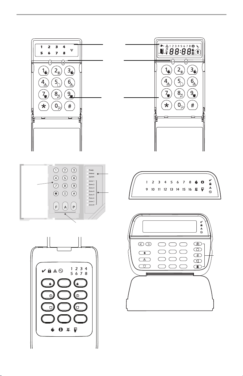
System Keypads
LCD5511
PC1555RKZ
PC1555RKZ
Number
Pad
Display
System
Lights
Number
Pad
Status
Lights
Zone
Lights
PK5508/PK5516
PK5500/PK5501
PC1404RKZ
2
1
5
4
8
7
0
*
Emergency Keys
3
6
9
#
1 2 3
4 5 6
7 8
*
2
9
0
#
Stay
Away
Chime
Reset
Quick
Exit
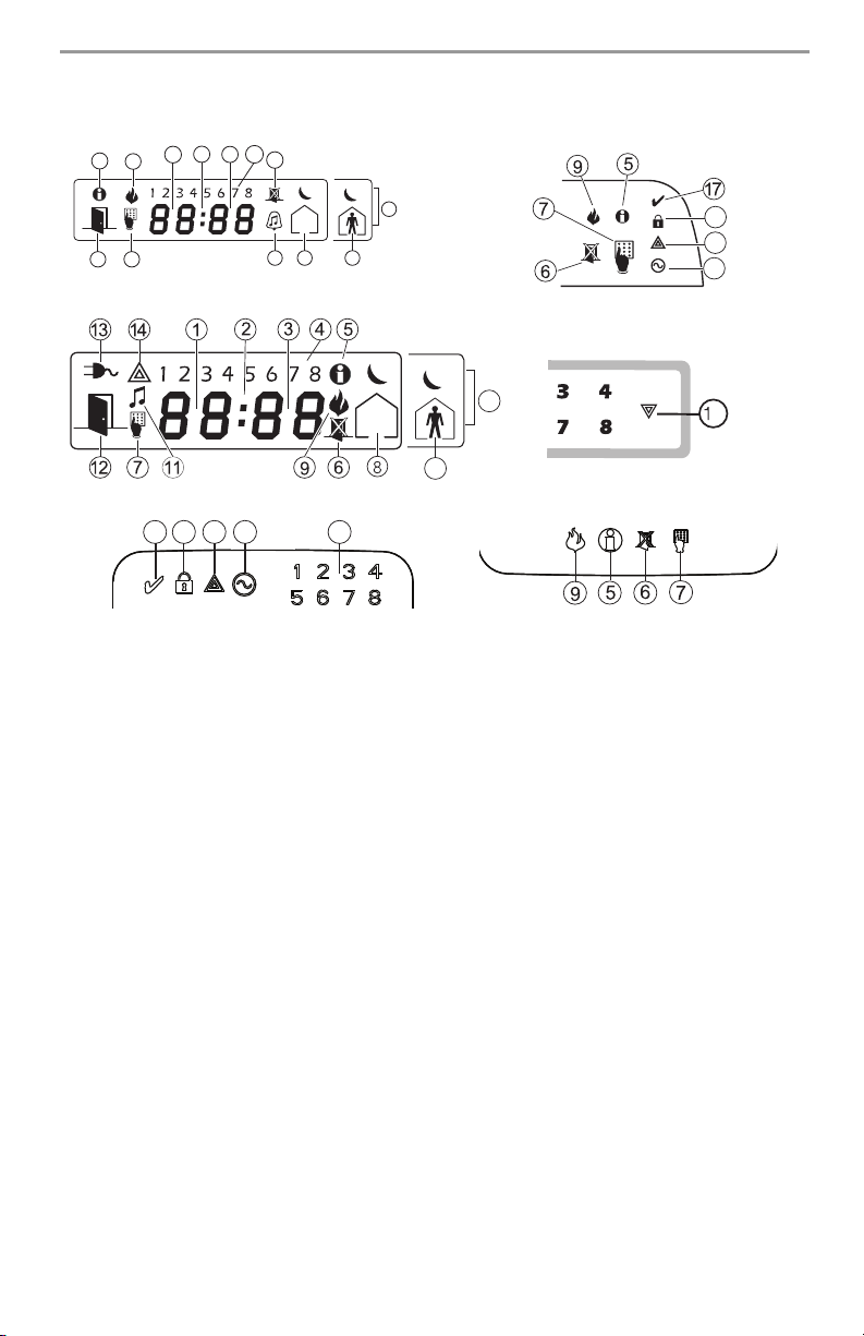
Keypad Display Symbols
PK5501
2
3
5
1
9
4
6
PK5508/5516
12 7
15
11
10
8
18
14
13
LCD5511
LED5511
15
10
PC1404RKZ
181714
13
1 Clock Digits 1, 2 – These two digits indicate the hour digits when the local clock is active, and
identify the zone when the OPEN or ALARM icons are active. These two digits scroll one zone
per second from the lowest zone number to the highest when scrolling through zones.
2 : (Colon) – This icon is the hours/minutes divider and will flash once a second when the local
clock is active.
3 Clock Digits 3, 4 – These are the minute digits when the local clock is active.
4
1 to 8 – These numbers identify troubles when
5 Memory – Indicates that there are alarms in memory.
6 Bypass – Indicates that there are zones automatically or manually bypassed.
7 Program – Indicates that the system is in Installer’s Programming or the keypad is busy.
8 Away – Indicates that the panel is armed in the Away Mode.
9 Fire – Indicates that there are fire alarms in memory.
10 Stay – Indicates that the panel is armed in the Stay Mode.
11
Chime – This icon turns on when the Chime function key is pressed to enable Door Chime on
the system. It will turn off when the chime function key is pressed again to disable Door Chime.
12 OPEN – This icon is used with clock digits 1 and 2 to indicate violated zones (not alarm) on the
system. When zones are opened, the OPEN icon will turn on, and 7 segment displays 1 and 2
will scroll through the violated zones.
13 AC – Indicates that AC is present at the main panel.
14 System Trouble – Indicates that a system trouble is active.
15 Night – Indicates that the panel is armed in the Night Mode.
16 System - Indicates one or more of the following:
Memory – Indicates that there are alarms in memory.
Bypass – Indicates that there are zones automatically or manually bypassed.
System Trouble – This icon is displayed when a system trouble is active.
17 Ready Light (green) – If the Ready light is on, the system is ready for arming.
18 Armed Light (red) – If the Armed light is on, the system has been armed successfully.
4
[][2] is pressed.
6
3
IMPORTANT NOTICE
A security system cannot prevent emergencies. It is only intended to alert you and – if included –
your central station of an emergency situation. Security systems are generally very reliable, but they
may not work under all conditions, and they are not a substitute for prudent security practices or life
and property insurance. Your security system should be installed and serviced by qualified security
professionals who should instruct you on the level of protection that has been provided and on system operations.
LCD Keypads
The Liquid Crystal Display (LCD) on the PK5500 displays prompts and system information on two 16character lines.
Where “< >” appears, more information can be accessed by using the arrow (< >) keys. Press [<] to
see the previous function or item of information. Press [>] to advance the display to next function or
item of information.
Press the keys on the number pad as prompted by the LCD display to view alarms or troubles, to arm
and disarm the system and to bypass zones.
To exit a function and return to the Ready state, press [#].
To select a function, press [].
PK5500 Language Selection
Your keypad may have the capability to display messages in different languages.
1. Press and hold both keys simultaneously.
2. Using the keys, scroll through the available languages.
3. Press to select your desired language.
Arming and Disarming the System
Arming the System
Arming from an LED Keypad:
If the Ready light is ON, the system is ready for arming. If the Ready light is OFF, check to see that all
doors and windows are closed and that motion is stopped in areas covered by motion detectors. The
system cannot be armed unless the Ready light is ON, indicating that all zones are closed and the
system is in the Ready state.
Enter your access code. As each digit is entered, the keypad sounder will beep. If the access code
was entered incorrectly, the keypad buzzer will sound steadily for one second. If this occurs, press
the [#] key and re-enter your access code. If the correct access code is entered, the keypad sounder
will beep quickly and the Armed light will come ON. Exit the premises through the door indicated by
your installer as the Exit/Entry door.
The panel will provide an exit delay period, indicated by keypad beeps, for you to exit the premises
without causing an alarm. At the end of the exit delay period, all keypad lights except the Armed
light will turn OFF and the system will be armed. You can restart the exit delay once by pressing the
Away button before the exit delay expires. The exit delay time can be changed by your installer.
Arming from an LCD Alphanumeric Keypad:
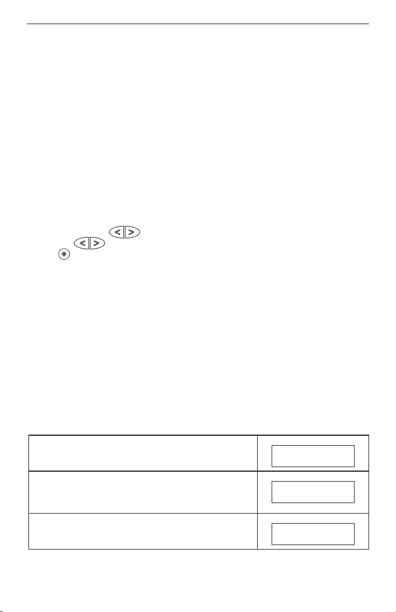
When this message appears, one or more zones are not secured.
To secure the system, close all doors and windows and cease all
motion in areas covered by motion detectors.
Secure System
Before Arming <>
When this message appears, use the arrow (< >) keys to verify
that the system is clear of troubles and that no zones are bypassed
unintentionally (see "Bypassing Zones” on page 13 and "Viewing
Trouble Conditions” on page 14).
If this display is showing, the system is in the Ready state and may
be fully armed. To arm the system, enter your access code.
4
System is
Ready to Arm <>
System is
Ready to Arm
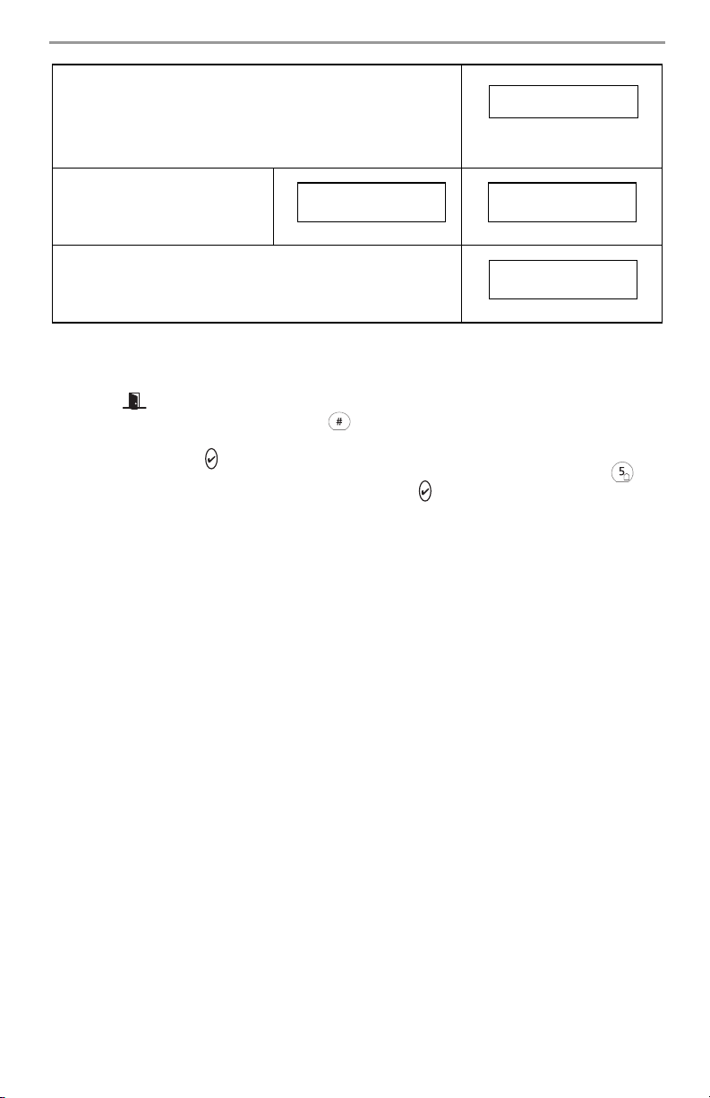
Once the correct access code has been entered, the display will be
as shown. The panel will provide an exit delay period, also
indicated by keypad beeps, for you to exit the premises without
causing an alarm. You can restart the exit delay once by pressing
the Away button before the exit delay expires. Exit through the
door indicated by your installer as the Exit/Entry door.
One of these messages will be
displayed once the exit delay
expires and the system is fully
armed.
If this message appears, be aware of which zones are bypassed
and why (see "Bypassing Zones” on page 13).
NOTE: If you arm the system with a zone bypassed or with a trouble present, your security
protection is reduced.
System Armed in
Stay Mode <>
Exit Delay in
Progress
System Armed in
Away Mode <>
* Warning *
Bypass Active
Arming from an LCD Fixed Message/Icon Keypad
Before you can arm your system, all the zones must be closed. If some zones are open, the keypad
will display , and the Ready light will be off.
To see the numbers of the open zones, press . Before you try to arm your system, go to the open
zones and close all doors and windows. Make sure no one is present in zones with motion detectors.
If the green Ready light is ON, the system is ready for arming.
To arm the system, enter your access code and leave through the entry/exit door, or press and
hold for 2 seconds (if enabled). If the red Armed light is ON, the system has been armed
successfully.
Alternate Arming Methods
Away Arming
Arming the system in the Away mode activates all interior and perimeter zones. If motion is detected
in the interior zones, or if one of the perimeter zones is violated, the alarm sequence will begin.
To arm in the Away mode, enter your access code and exit the premises through a designated Exit/
Entry door. The system will recognize that occupants have left the premises. Once the exit delay
expires, the system will be fully armed.
You can restart the exit delay once by pressing the Away button before the exit delay expires.
Audible Exit Fault
In an attempt to reduce false alarms, the Audible Exit Fault is designed to notify you of an
improper exit when arming the system in the Away mode. In the event that you fail to exit
the premises during the allotted exit delay period, or if you do not securely close the Exit/
Entry door, the system will notify you that it was improperly armed in two ways: the
keypad will emit one continuous beep and the bell or siren will sound. If this occurs, you
must re-enter the premises, enter your access code to disarm the system, and then follow
the arming procedure again, making sure to exit the premises in the proper fashion. Your
installer will inform you if the Audible Exit Fault feature has been enabled on your system.
Stay Arming
This feature, if enabled by your installer, will allow you to arm the perimeter zones (i.e., doors and
windows) while leaving the interior zones (i.e., motion sensors) inactive so that you can remain on
the premises while the system is armed. When you enter your security code to arm the system and
do not exit the premises through a designated Exit/Entry door, the system will arm in the Stay mode,
automatically bypassing the interior zones.
The interior zones can be reactivated at any time by entering [][1] at any keypad. If you reactivate
the interior zones, be sure to only inhabit areas not covered by motion detectors. To access areas
protected by motion sensors, you must enter your security code and disarm the system.
5

Night Arming
To fully arm the system when it has been armed in Stay Mode, press [][1] at any keypad, or press
the night arming function key if it has been configured by your installer. All interior zones will now
be armed except for devices programmed as Night Zones.
Night zones are only armed in Away mode. This permits limited movement within the premises
when the system is fully armed. Ensure that your installer has provided you with a list identifying
zones programmed as night zones.
When the interior zones have been activated (i.e., [][1]), you must enter your access code to disarm
the system to gain access to interior areas that have not been programmed as night zones.
Arming Without Entry Delay
If you wish to arm your system without the entry delay, enter [][9] then your access code. The
Armed light will flash as a reminder that the system is armed and has no entry delay. An entry
through any zone programmed as a delay zone will create an instant alarm.
Quick Arm
When the Quick Arm feature is enabled, the system may be armed by simply pressing [][0] instead
of your access code. Please note that pressing [][0] will only allow you to arm the system; to
disarm, you must enter a valid access code. Your installer will inform you if the Quick Arm feature
has been enabled on your system.
Auto Arming
Your system can be programmed to automatically arm itself according to a programmed schedule.
To program the auto arm time, enter [][6] followed by your master code. Press [3]. Enter the time
using the 24 Hr format (00:00 - 23:59).
To enable or disable the auto arm feature, enter [][6] followed by your master code. Press [2] to
either enable or disable the feature. The keypad will beep 3 times if the feature is ON and once if it
is OFF.
NOTE: The correct system time and date must be programmed in order for the auto arm feature
to function properly. Please see "Setting the System Date and Time” on page 14 for instructions.
Quick Exit
When the Quick Exit feature is enabled, pressing [][0] while the system is armed will provide a two
minute window for you to exit the premises. During this time, you may open and close the
designated Entry/Exit door only once. Once the door is closed, the panel will end the two minute
quick exit delay. If the door is opened again, if the door is not closed after two minutes, or if another
zone is opened, the panel will begin the entry delay. Your installer will inform you if the Quick Exit
feature has been enabled on your system.
Disarming the System
Disarming from an LED Keypad:
Enter the premises through a designated Exit/Entry door; entering by any other door will sound an
immediate alarm. As soon as the Exit/Entry door is opened, the keypad will beep to indicate that the
system should be disarmed. Go to the keypad and enter your access code. If an error is made
entering the code, enter your code again. As soon as the correct code is entered, the Armed light
will go out and the keypad will stop beeping.
The correct access code must be entered before the entry delay period expires. If a valid access code
is not entered during this time, the system will go into alarm. The entry time delay may be changed
by your installer.
If an alarm occurred while the system was armed, the Memory light and the zone light
corresponding to the zone that caused the alarm will flash for 30 seconds. After the 30-second
period, the Memory light and zone light will stop flashing and the panel will return to the Ready
state. Pressing the [#] key during the 30-second period will cancel the alarm memory display. To view
other alarms, press [][3].
If a trouble was detected when the panel is disarmed, the Trouble light will turn ON. (See "Viewing
Trouble Conditions” on page 14 to determine the source of the trouble.) Please note that troubles
will not display while the system is in the Alarm Memory Display mode.
6
 Loading...