

Page 1

D
Pac® 5000 CO, H2S, O
Instructions for Use
2
ϝΎϤόΘγϻ ΔϘϳήσ
ʹʥʮʩʹ ʺʥʠʸʥʤ
Page 2
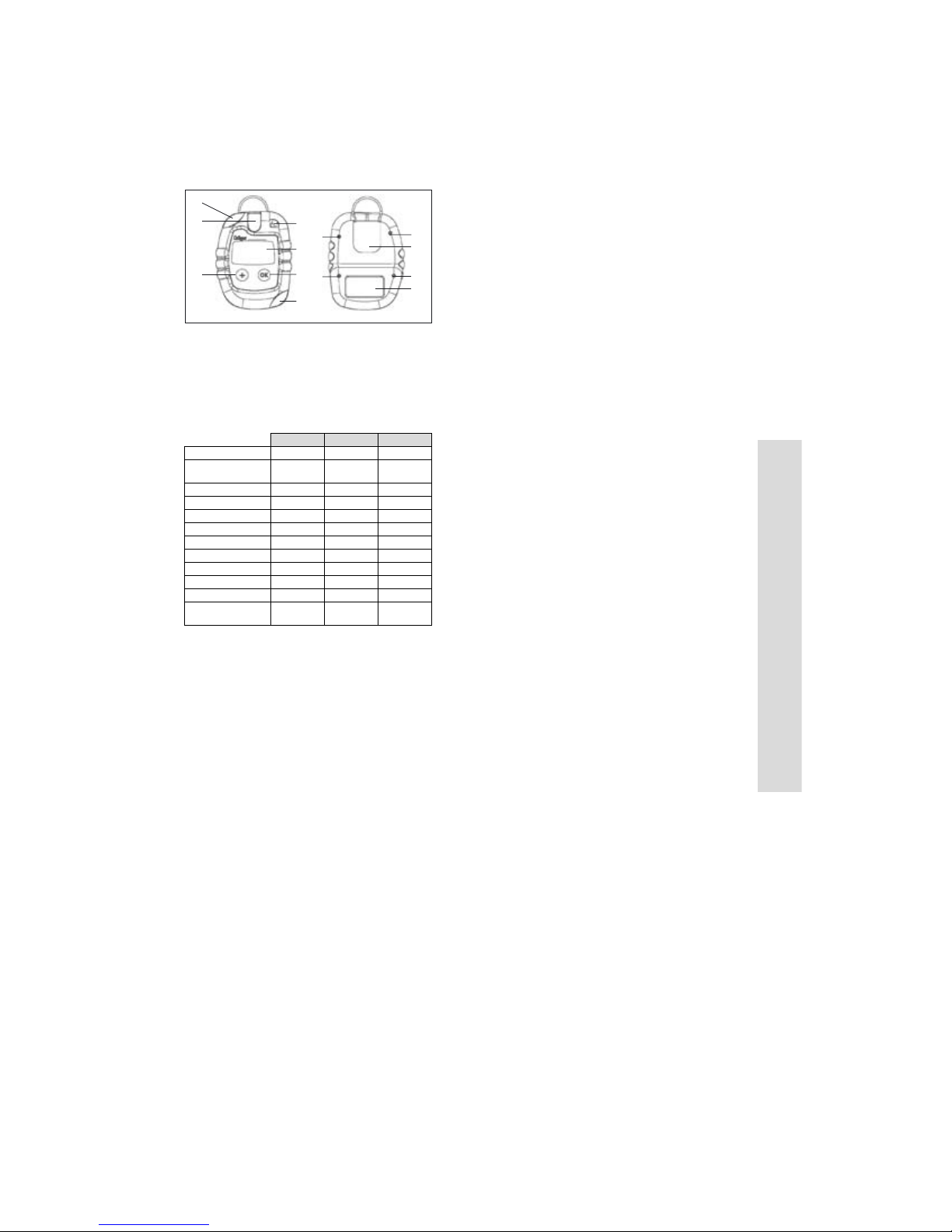
1 What is what
1
6
5
1 Alarm LED 6 Gas Opening
2 Horn 7 Screw
3 Concentration Display 8 Clip
4 OK Key On/Off/Alarm Acknowledge 9 Label
5 + Key Off/Bump Test
2 Standard configuration
Order No.
Measuring Range 0 to 500
Vibrating alarm Yes Yes Yes
Alarm Threshold A1 30 ppm 10 ppm 19 vol.-%
acknowledgeable Yes Yes No
latching No No Yes
Alarm Threshold A2 60 ppm 20 ppm 23 vol.-%
acknowledgeable No No No
latching Yes Yes Yes
Display numeric numeric numeric
Life Signal on on on
Turning the
instrument off
2
7
3
4
7
1
1)
CO H2S O
0 to 100
ppm
always
allowed
ppm
always
allowed
2
0 to 25
vol.-%
always
allowed
7
8
7
9
3 Safety advisory
— The use of the Dräger Pac 5000 instruments assumes a
complete knowledge and adherence to the users manual.
— The Pac 5000 may only be used in areas subject to
explosion hazards which are explicitly covered under the
Ex Approvals which have been given to the Pac 5000.
— Pac 5000 is not for use in oxygen-enriched atmospheres.
— Please check calibration before safety relevant use.
— The performing of calibration and bump testing shall be
conducted according to local regulations.
— Dräger Safety AG & Co. KGaA is not responsible for
damages incurred when the above guidelines are not
explicitly adhered to.
4 Intended Use
— Personal gas alarm in the workplace.
5 Operation
5.1 Remaining life of the instrument
— Once activated check the remaining life by pressing [+]
while instrument is turned off. The gas to be measured will
be shown. After another press “d” will be shown.
After another press the remaining time in days will be
shown, e. g. “CO”, “d”, “750”.
_____________
1) Please be aware of special settings by customer requirements.
2) For O
A1 is the lower alarm threshold, used to indicate oxygen deficiency
2
5.2 Activating a new instrument
— Press and hold [+] for approximately 3 seconds while
“3, 2, 1“ appears in the display. The instrument’s usable
life is now started. The number of days remaining is
shown in alternation with “d” until the + key is released.
e.g. “750”, ”d”, “750”, “d”, ...
5.3 Turning the instrument on
— Press and hold [OK]. The display counts down until
startup: “3, 2, 1”.
— All display segments are lit. Next, the LED, Alarm and
Vibrating alarm are activated in sequence. Please check
these before each use.
— The instrument will perform a self test.
00123806_1.eps
— The software version and the gas name are displayed.
— The number of days of remaining operation are shown,
e. g. “750”, “d”.
— The A1 and A2 alarm limits are displayed.
— When the instrument is first activated, a sensor warm up
time of up to approx. 5 minutes is needed. The gas name
flashes until the warm up time has passed.
5.4 Before entering a working place
— After turning the instrument on, the gas name to be
measured will normally be shown in the display.
— Check for the notice icon [!]. When lit, it is recommended
that you perform a bump test as described in section 5.5.
— Clip the instrument to clothing before working in or near
potential gas hazards.
— Insure that the gas opening is not covered and that the
instrument is also near to your breathing area.
2)
5.5 Performing a “bump test” with gas
— Prepare a Dräger test gas cylinder with 0.5 l/min and a
gas concentration higher than the alarm threshold to be
tested.
— Connect Pac 5000 and the test gas cylinder to the
calibration adapter or to the Dräger Bump Test Station.
— To achieve the bump test mode press and hold [+] for
3 seconds. The instrument beeps twice, quickly. The
Display begins to flash slowly. Release [+].
— Open the regulator valve to let test gas flow over the
sensor.
— If gas concentration exceeds the alarm thresholds A 1 or
A 2 the corresponding alarm will occur.
— To finish the bump test press [OK] for 1 second, the [!]
icon is removed from the display and the instrument
returns to the measuring mode.
— If during the bump test no alarm occurs within 1 minute,
the instrument beeps three times to indicate failure. The
[X] icon is lit; error code 240 is shown for 10 seconds.
Afterwards, “-- -- --“ is shown instead of the gas name, and
the [X] icon stays lit. In this case the bump test can be
repeated or the instrument can be calibrated.
— The result of the bump test (passed or failed) will be
stored in the event logger (see section 5.8).
— The bump test can also be made by an automatic function.
This function can be activated using the PC software
Pac Vision or CC Vision (see section 5.9).
5.6 During operation
— If the allowable measurement range is exceeded or a
negative drift occurs, the following will appear in the
display: “_ _ _” (too high concentration) or “___” (negative
drift).
— Alarms are indicated as described in section 6.
— Continuous function of the instrument is indicated by the
life signal, which is a beep every 60 seconds, if
configured (see section 2).
5.7 Turning the instrument off
— Simultaneously hold both keys for approximately 2
seconds until “3” appears in the display. Continue to hold
both keys until the countdown is finished. The alarm and
LED will be activated momentarily.
5.8 Event logger
— Pac 5000 is equipped with an event logger. The event
logger stores 60 events. If event No. 61 occurs the logger
overwrites the oldest stored event.
— For download of the stored data connect Pac 5000 to a
PC using the connecting cradle or the E-Cal System. The
stored data can be downloaded with installed software
Pac Vision or Gas Vision.
English
Page 3

English
5.9 Calibration and configuration
— For calibration or individual configuration connect Pac
5000 to a PC using the connecting cradle or the E-Cal
System. Calibration and configuration can be done with
installed software Pac Vision or CC Vision. A calibration
“due date” can be set using the operation timer (in days).
5.10 Adjustable operation timer (in days)
— Pac 5000 is equipped with an adjustable operation timer.
The operation timer can be used to set an individually
operation period e. g. to adjust a “calibration due date”,
an “inspection due date”, an “out of order date” etc.
— To adjust the operation timer connect Pac 5000 to a PC
using the connecting cradle or the E-Cal System. The
adjustment can be done with installed software Pac
Vision or CC Vision.
6 Alarms
6.1 Concentration Pre/Main Alarms
— The alarm will activate whenever the alarm thresholds A1
or A2 are exceeded. The instrument is equipped with a
vibrating alarm. It vibrates in parallel to these alarms.
— During an A1, the LED will blink and the alarm will sound.
— During an A2, the LED and alarm tone will repeat in a
double repeating pattern.
— The display will alternate between the measurement value
and “A1” or “A2”.
— The alarms may, according to the selected configuration,
be acknowledged or turned off. (See section 2.)
“Acknowledgeable”: alarms and LED can be
acknowledged by pressing [OK] for 1 second.
— “Latching”: The alarm will only deactivate when the
concentration falls under the alarm threshold and then
[OK] is pressed for 1 second.
— If the alarm is not latching, the alarm will deactivate as
soon as the concentration falls under the alarm threshold.
6.2 Battery pre/main alarms
— When the battery pre-alarm is activated, the audible alarm
sounds and the LED blinks, and the “low battery” icon
»«
flashes.
— To acknowledge the pre-alarm, push [OK] for 1 second.
— After the first battery pre-alarm, the battery will last for
approx. 1 further week and the “low battery” icon stays lit.
— When the battery main alarm is activated, the audible
alarm sounds in a repeating pattern of 2 repeating tones
and the LED blinks in the same pattern.
— The battery main alarm is not acknowledgeable; the
instrument will automatically turn off after approx. 1
minute.
— In case of a very low battery, the internal voltage monitor
could activate the LED’s.
6.3 Changing the battery
— Do not change the battery in explosion-hazard areas!
— The instrument contains a replaceable lithium ion battery.
— The battery is part of the Ex approval.
— Only the following battery types shall be used:
— Duracell DL 123 Lithium Type CR123A, 3 V
— ………
— ………
— Turn the instrument off.
— Unscrew the 4 screws from the back case.
— Open the front case and remove the depleted battery.
— Insert the new battery according to specified polarity
(+/–).
— Place front case back and fasten it by tightening the 4
screws of the back case.
6.4 Handling of exhausted batteries
—Caution:
— Never throw them into a fire!
— Never attempt to charge them!
— Never attempt to open them, danger of explosion!
— Dispose of exhausted batteries only as special waste in
accordance with local regulations.
— Spent batteries may be returned to Dräger for disposal.
6.5 Usable life alarm
— Before the end of the instrument’s usable life, a warning
period begins. During this period the remaining life time
flashes just after turning the instrument on, e. g. “30”/“d”.
— To acknowledge this message [OK] must be pressed for
approx. 1 second. After that, the instrument can be used
further.
— After the usable life has expired the text “0“/“d“ will
alternate in the display and cannot be acknowledged.
Pac 5000 will not longer measure and may be returned to
Dräger for recycling.
6.6 Instrument alarm
— The alarm and LED will be activated three times,
periodically.
— The [X] icon will be lit, with a 3 digit error code shown in
the display.
— If an error appears in the display see section 6.7 and if
necessary please contact DrägerService.
6.7 Trouble shooting errors
Code Cause Remedies
100 Flash / EEprom write
fail
102 AD system defect Contact DrägerService
104 Flash check sum
wrong
107 Self test failed Contact DrägerService
210 Fresh air calibration
failed
220 Span calibration failed Repeat operation
240 Bump test failed Repeat operation or
Contact DrägerService
Contact DrägerService
Repeat operation
calibrate instrument
7 Technical Specifications
Environmental Conditions
During
operation
Conditions
for storage
Ingress
protection
Operating
times
Battery life
(typical at
o
25
C)
Intensity of
alarm
Dimensions 54 x 84 x 34 mm
Weight 120 g
Approvals
(only
approvals
printed on the
instrument
are valid)
o
–30 to 50
700 to 1300 hPa
5 to 95% relative humidity
0 to 40
30 to 80% relative humidity
IP 65
2 years (typical at 25
24 hours of use per day,
2 minutes alarm per day:
CO, H
O2: >3600 hours
typical 90 dBA at 30 cm
CE Sign (89/336/EEC , 94/9/EC)
DMT 98 ATEX E021X
II 2 G EEx ia IIC T4, –40
I M1 EEx ia I, –40
UL Class I, II, III Div I, Group A, B, C, D, F, G,
Temp Code T4, Exia
CSA Class I, Groups A, B, C, D, Exia Temp
Code T4
C
o
C
S: >8000 hours
2
o
C)
o
C ..55 oC
o
C ..55 oC.
8 Sensor Specifications
Reproducibility
Zero point:
Sensitivity:
Temperature Influence
Zero point:≤ ±5 ppm≤ ±2 ppm≤ ±0.2 vol.-%
Sensitivity:
Drift (20
Zero point:
Sensitivity:
Please be aware of possible sensor cross sensitivities (see
Sensor Data Sheet XX XX XXX).
CO H2S O
≤
±5 ppm≤ ±2 ppm≤ ±0.2 vol.-%
≤
±3 % of
measured value
≤
±0.4 % of
measured
value / K
o
C)
≤
±5 ppm/a≤ ±1 ppm/a≤ ±0.5 vol.-%/a
≤
±1 % of
measured
value / month
≤
±5 % of
measured value
≤
±5 % of
measured value
≤
±1 % of
measured
value / month
2
≤
±1 % of
measured value
≤
±1 % of
measured value
≤
±1 % of
measured
value / month
 Loading...