

Page 1
GE
Sensing
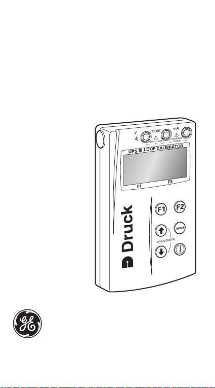
Druck UPS-III Loop Calibrator
User manual -K0317
Page 2
Approved Service Agents
For the list of service centres visit our web site:
Symbols
www.gesensing.com
This equipment meets the requirements
of all relevant European safety
directives. The equipment carries the
CE mark.
This symbol, on the instrument,
indicates that the user should refer to
the user manual.
Do not dispose of this product as
household waste. Use an approved
organisation that collects and/or
recycles waste electrical and electronic
equipment. For more information:
Contact us at www.gesensing.com
Page 3
UPS III Loop Calibrator
Introduction
The Druck UPS III Series of loop calibrators can supply power
(source mode) and produce readings (measure mode) to
perform f ield calibrations on 2-wire devices. The set-up menu
enables the user to “source” or “measure” in either voltage or
current and to perform continuity tests. These user
instructions include the operation, safety instructions and
installation requirements for the loop calibrator.
Specifications
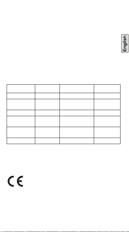
Accuracy
Values in table below includes temperature effects 17°C to 27 °C
Outside these limits .................. 0.003%/°C(0.0015%/°F)
Calibration Reference................ 22°C ±1°C/RH45%±15%
Mode Range Accuracy Remarks
Source mA 0 to 24 mA* 0.01% rdg + 2 lsd V-max. 75V
Source mA +
24V
Measure mA 0 to 24 mA* 0.01% rdg + 2 lsd V-max. 75V
Measure mA
+ 24V
Measure V 0 to 60V* 0.02% rdg + 4 lsd R-measure
Continuity <100Ω ** -1 mA
* Resolution 0.001 lsd least significant digits
** Audio + visual rdg reading
Hart® communications...............menu selectable 220Ωloop resistor
Operating Temperature...... -10°C to 50°C (-14°F to 122°F)
Storage Temperature......... -20°C to 70°C (-4°F to 158°F)
Conforms to ......... EN61010, EN 61326-1(1997)+ A1(1998)
Electrical Power Supply
.................................... 4 x 1.5 V alkaline size AA or
Universal power supply {see accessories}
0 to 24 mA* 0.01% rdg + 2 lsd R-max 1k
0 to 24 mA* 0.01% rdg + 2 lsd R-measure
This loop calibrator meets the essential protection
requirements of the relevant EEC directives.
at 20 mA
15
Ω
Ω
1M
Ω
1 K0317 Issue No. 3
Page 4

Physical
Dimensions......................... 77 x 129 x 24 mm(3” x 5” x 1”)
Weight .................................................. 275 grams (9.7 oz.)
Terminals ...................................4 mm sockets {gold plated}
Case ....................................................... High impact ABS
Relative Humidity....................................................0 to 90%
Safety
This symbol, on the loop calibrator, indicates that the
user should refer to the user guide or manual.
Batteries
• Remove batteries from the loop calibrator immediately
when discharged and before storage.
• Dispose of batteries in accordance with local regulations
and battery manufacturers' instructions.
• When storing and transporting batteries make sure they
cannot be short circuited.
Power Supply
The power supply for this loop calibrator can be the internal
non-rechargeable batteries or the external Universal power
supply unit (see accessories).
Battery life >
The display shows with low battery power.
Battery Replacement
• Unscrew and remove the securing screw from the battery
panel.
• Replace the batteries, check the polarity of the batteries.
• Refit and secure the battery panel.
Accessories
Assy 305 Test lead set
191-129 Power supply, Universal, 100-240 V a.c. 47-63Hz
38016 Carrying case
38023 Protective rubber boot
75 hours in measure mode
18 hours at 12 mA (source mode)
>
K0317 Issue No. 3 2
Page 5
OPERATION
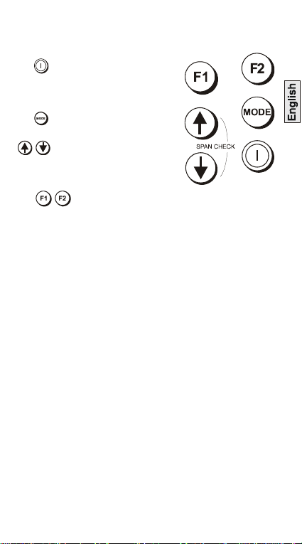
Keys
The key switches the calibrator
on and off. Press and hold for 2
seconds.
The key changes the measure or
source operating mode. Pressing the
keys makes menu selections,
sets numerical values and controls
step and ramp functions (up/down).
The select advanced
functions shown on the bottom of the display. When no key is
pressed for 10 minutes, the calibrator times out and switches
off. To disable this automatic time out, select autpower down
in the set-up menu.
3 K0317 Issue No. 3
Page 6
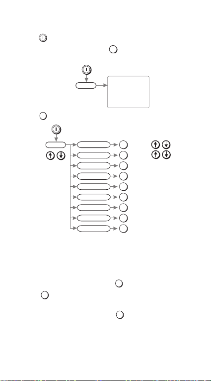
Operating Modes
F1
F1
Serial number
VERSION
CAL. DATE
HART
BATTERY
Information
F2
F2
Resolution
adjust
F2
Contrast
adjust
F2
Range
4-20 mA/0-20mA
F2
Source unit
mA/%
F2
Hart® ON/OFF
F2
Aut power down
ON/OFF
F2
Decimal
.,/
F2
Access code
menu
F2
Calibration
menu
F2
F1
F2
F2
Pressing
the start-up sequence. Pressing , at this time, the display
shows the information screen:
Pressing , at this time, the display shows the set-up screen:
switches the instrument on and the display shows
The calibrator can be used in two modes
measu re
or
source
Measure mode
The display shows the measured value; depending on the
settings made in set-up and advanced settings:
When measuring current pressing enables linear or flow,
pressing enables mA or % (value of 4 to 20 mA or 0 to 20
mA).
When measuring voltage pressing changes the resolution
between 0.00V and 0.000V.
To measure continuity the displays shows an open or closed
switch symbol with an audible signal on switch closure.
K0317 Issue No. 3 4
.
Page 7

Connect the loop calibrator to the device to be tested:
and Measure mA
Press the mode key and select [Measure mA]. External power
supplies Vmax = 60 V for the loop. The calibrator measures
the current flow of the loop.
Closed loop current measurement from transmitter test
terminal.
* test terminal
Measure mA with 24 V
Press mode key and select [Measure mA and 24V]. The
calibrator supplies 24 V for the loop, maximum 24 mA
5 K0317 Issue No. 3
Page 8

Measure Volts
Press mode key and select [Measure V], measure range 60V,
maximum impedance 1 Mohm.
Continuity Test
Press mode key and select [Continuity Test].
Pressing switches the audible signal on/off.
K0317 Issue No. 3 6
Page 9

Source Mode
The display shows the source value in mA or % value of 4 to 20
mA or 0 to 20 mA, linear or flow depending on the settings
made in set-up and advanced settings.
Source mA
Press mode key and select [Source mA]. The calibrator
supplies maximum output of: 24 mA; Vmax = 60; receiver input
Rmax = 1kOhm.
Source mA with 24V
Press mode key and select [Source mA and 24V]. The calibrator
supplies maximum loop power of: 24 V and 24 mA.
7 K0317 Issue No. 3
Page 10

Advanced Options in a Source mode
MODE
F1
Lin
Flow
Valve
Step
Auto-step
Span Check
Ramp
Time (M:SS)
Time (M:SS)
Adjust +1/ -1 second
Adjust +1/ -1 second
F2
Mode
mA source
mA source & 24V
select
Enter
Advanced
select
F2
select
F2
F2
F2
Press the key and select mA Source or mA Source & 24V.
Use and
(Enter) to select the function.
Press the key (Advanced) and the display shows:
Linear simulates linear transmitt ers.
Flow simulates flow transmitters.
Valve simulates valve control signals.
Use and
(Enter) to select the Advanced option:
Advanced
Step 25% steps for linear and flow - fixed values for
valve.
Auto-step The same as step with a timed step interval.
Span Check Step between 4 (or 0) mA and 20 mA.
Ramp Automatic ramp between 4 (or 0) mA and 20 mA.
Note: Ramp function not available for valve selection.
Use
to quit.
The display returns to the selected source
mode with the advanced setting available.
K0317 Issue No. 3 8
Page 11

Operation of Advanced Options
Advanced
%
+100.0%
mA
m
A
(
24
V
)
CO
M
V
+24.000
mA
Hart®
communicator
W
220W
menu selectable loop resistor
Press the key to switch the advanced setting on and off:
on or off
e.g.
Press or to:
step the output up or down.
step the span check maximum or minimum
start the “ramp”.
Press then to start:
continuous auto-step.
or
continuous ramp cycle.
Hart® Application
This application allows mA measure and source modes to be
used through the Hart® communicator.
9 K0317 Issue No. 3
Page 12

blank page
K0317 Issue No. 3 10
Page 13

Maintenance
• Return the loop calibrator to an authorised repair centre
for any repairs, it cannot be repaired on-site.
• To keep the loop calibrator accurate a calibration check
should be carried out once per year.
Cleaning
• Clean the loop calibrator case with a moist, lint-free cloth
and weak detergent.
11 K0317 Issue No. 3
Page 14

Battery Replacement
Only use the battery type listed on page one.
Unscrew and remove the securing screw from the battery panel.
Replace the batteries, check the polarity of the batteries. Refit and
secure the battery panel.
K0317 Issue No. 3 12
Page 15

Calibration Instructions
General
The instrument is supplied by the manufacturer, complete
with calibration certificate(s). A calibration period of 12
months is recommended. The actual calibration interval
depends on instrument usage and the total measurement
uncertainty acceptable for the specified application.
The
UPS-III
is a very precise measuring instrument and the test
equipment and conditions of test must be suitable for the type
of work. The calibration check and calibration adjustment
should be carried out in a controlled environment by a
calibration technician*.
The manufacturer offers a comprehensive and, if required,
UKAS accredited calibration service.
*
A calibrati on technician must have the necessary technical knowledge,
documentation, special test equipment and tools to carry out the calibration
work on this equipment.
Calibration Equipment
The following tables give the accuracy requirements for the
calibration equipment and the UPS-III.
Calibration requires a stable temperature of 21° ±1°C (70° ±2°F).
UPS-III measure mode
Applied mAPermitted UPS-III error
0 0.002 0
4 0.002 0.00014
12 0.002 0.00030
20 0.002 0.00046
Table 1
mA measure
(mA)
Calibrator error
(mA)
13 K0317 Issue No. 3
Page 16

Table 2
Applied V Permitted UPS-III error
0 0.004 0.00040
20 0.004 0.00014
40 0.005 0.00064
50 0.005 0.00070
V measure
Calibrator error
(mV)
(mV)
UPS-III source mode
Applied mAPermitted UPS-III error
0 0.002 0
4 0.002 0.00012
12 0.002 0.00011
20 0.002 0.00015
Table 3
mA source
(mA)
Calibrator error
(mA)
Calibration Check
1.Connect the UPS-III to the electrical calibrator. Switch on the
electrical calibrator and allow it to thermally stabilise.
2.Switch on the UPS-III and allow the instrument to thermally
stabilise.
3.Set the UPS-III to mA measure, adjust the electrical calibrator
to apply the first value in the table 1. Record the reading of the
UPS-III.
4.Repeat step 3 for all the values in the table 1.
5.Compare the recorded values and the applied values. If the
difference is greater than the permitted error, the instrument
requires a calibration adjustment.
6.Repeat this procedure for V measure (table 2) and mA source
(table 3).
K0317 Issue No. 3 14
Page 17

Calibration Adjustment
1.Connect the UPS-III to the electrical calibrator. Switch on the
electrical calibrator and allow it to thermally stabilise.
2.Switch on the UPS-III and press , within two seconds to
select Calibration. Enter the access code [9410 factory
setting] and allow the instrument to thermally stabilise.
3.Select the parameter required for calibration. Use the
display menu to select the calibration values. After a
successful calibration enter the new calibration date.
15 K0317 Issue No. 3
Page 18

K0317 Issue No. 3 16
Page 19

17 K0317 Issue No. 3
Page 20

K0317 Issue No. 3 18
 Loading...