

Page 1
Haas Technical Documentation
Spindle - 40-Taper - Belt Drive - Drawbar
Assembly - Replacement
Scan code to get
the latest version
of this document
Translation
Available
Applies to machines built from:
December, 1989
AD0278 Rev B
Spindle - 40-Taper - Drawbar Assembly - Replacement
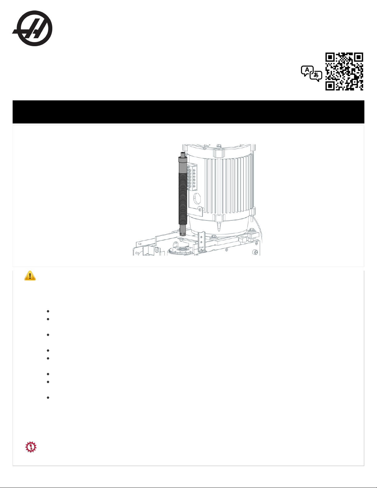
This procedure tells you how to replace the drawbar assembly.
Caution: When you do maintenance or repair on CNC machines and their components, you must always follow basic safety
precautions. This decreases the risk of injury and mechanical damage.
Do these steps before you do work in the machine or in the control cabinet:
Set the main circuit breaker to the [OFF] position.
Use an approved lock with an approved safety tag. Always follow lock-out procedures in accordance to local government
rules.
After turning off the machine, wait at least 5 minutes before working in the control cabinet, to allow power to dissipate. Wait
for the voltage indicator LED on the vector drive to go off completely.
Always turn off the main air supply when you work on any part of the pneumatic system.
Make sure to rest the spindle head on a block of wood when work is done on a vertical axis. This will prevent any unintended
movement that could result in the axis falling.
Never alter any safety circuits on the machine.
Never change any parameter while in DEBUG mode (Classic Haas Control) and the servos ON. Put the machine in
Emergency Stop mode to change any parameters.
Never operate the machine in DEBUG mode (Classic Haas Control).
You should not do machine repair or service procedures unless you are qualified and knowledgeable about the processes. Serious
damage to the machine components can result in costly repairs. The service technicians at your Haas Factory Outlet (HFO) have
the training and experience, and are certified to do these tasks safely and correctly. The repair and service work performed by your
HFO is protected with a limited warranty.
Danger: Some service procedures can be dangerous or life-threatening. DO NOT attempt a procedure that you do not fully
understand. If you have any doubts about doing a procedure contact your Haas Factory Outlet (HFO) and schedule a service visit.
Copyright 2017 by Haas Automation, Inc. No unauthorized reproduction | Last Published On June 16, 2016 1/3
Page 2
Prerequisites
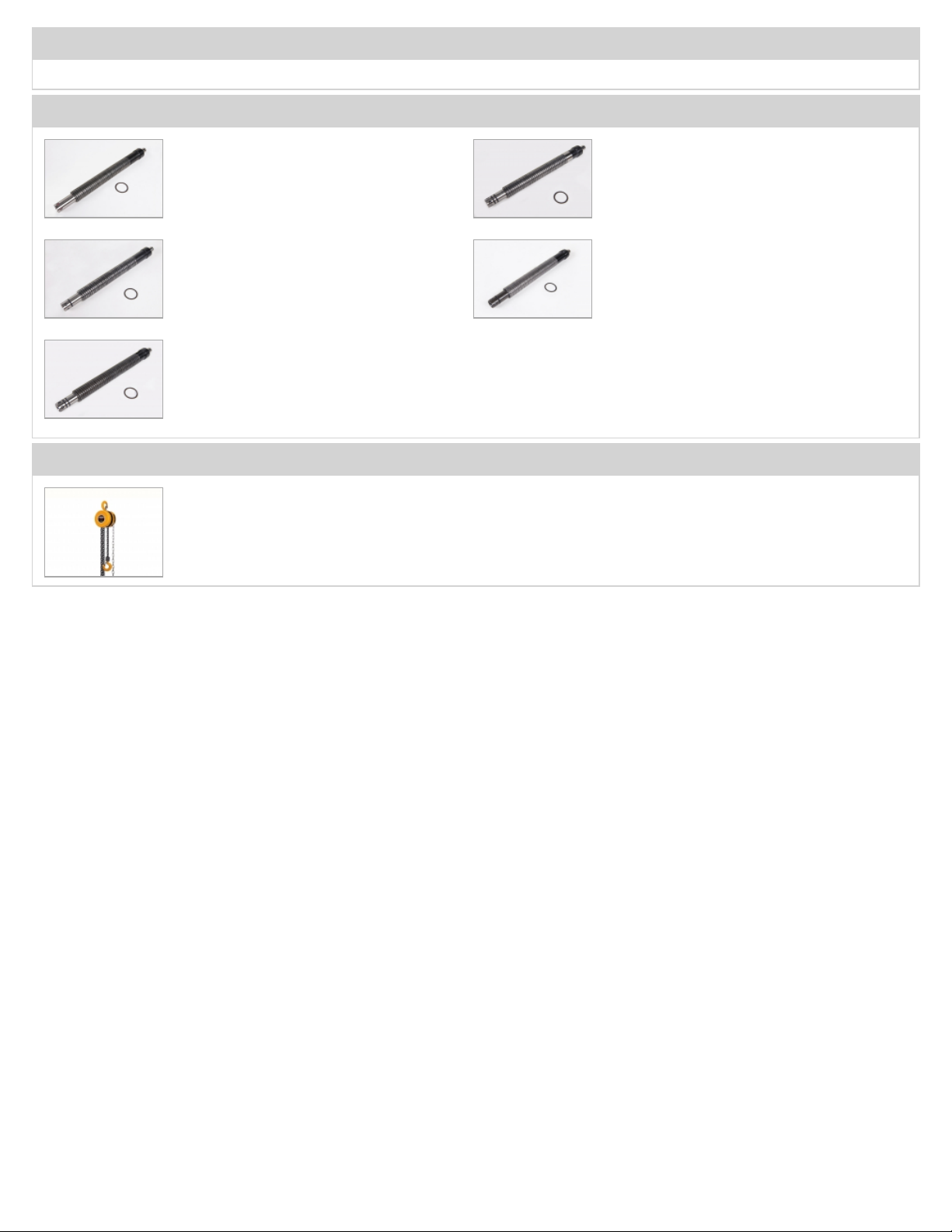
This procedure is applicable to (5) different kits. You use only (1) of the kits from the "Parts Included" section.
Parts Included
Tools Required
KIT 93-30-3410C
QTY: 1
DRAWBAR, 40T BELT DRIVE, 900 1300 LB
KIT 93-30-2406A
QTY: 1
DRAWBAR, 40T BELT DRIVE (15K),
900 - 1300LB
KIT 93-30-3410D
QTY: 1
DRAWBAR, 40T BELT DRIVE, 1000 1200 LB
KIT 93-30-3415F
QTY: 1
DRAWBAR, 40T BELT DRIVE, 1000 1200 LB
KIT 93-30-3415H
QTY: 1
DRAWBAR, 40T TSC BELT DRIVE,
1750 - 2100 LB
Gearbox machines: hoist that has a 200
lb (91 kg) capacity
Copyright 2017 by Haas Automation, Inc. No unauthorized reproduction | Last Published On June 16, 2016 2/3
Page 3

STEP 1
Push [EMERGENCY STOP] when you do maintenance on the machine.
Put a toolholder without a tool in the spindle. Close the primary air valve to the machine. Remove the tool release piston (TRP)
assembly [1]. Remove the retaining ring [2] from the spindle shaft. Install the TRP assembly [1]. Open the primary air valve to the
machine. Remove the toolholder from the spindle. Close the primary air valve to the machine. Remove the TRP assembly [1].
If the machine has a gearbox: Remove the (6) screws [4] from the gearbox base. Use the hoist [5] to lift the gearbox and spindle
motor assembly [6] until you can easily remove the drawbar [3].
Remove the used drawbar assembly [3]. Clean the bore of the spindle shaft. Make sure the balls [7] or o-rings from the used
drawbar assembly [3] did not fall into the bore of the spindle shaft.
Make sure the (5) balls [7] are fully in position at the end of the replacement drawbar [3]. Lightly push the drawbar [3] to install it
into the spindle shaft.
Caution: Install the drawbar [3] with light force so you do not damage the o-rings. Do not use a tool to hit the drawbar
into position.
Install the TRP assembly [1]. This lets you put a toolholder into the spindle. Open the primary air valve to the machine. Put a
toolholder without a tool in the spindle. Close the primary air valve to the machine.Remove the TRP assembly [1]. Install the
retaining ring [2] onto the spindle shaft.
If the machine has a gearbox: Install the (6) screws [4] into the gearbox base. Make sure the drive belts are moderately tight. If
the belts are too tight, they make noise at high speeds. If the belts are too loose, they vibrate. If you cannot adjust the drive belt
tension, speak to your local HFO. Torque the screws [4] on the gearbox base to 25 ft-lbs.
Install the TRP assembly [1]. Torque the screws to 45 ft-lbs.
Copyright 2017 by Haas Automation, Inc. No unauthorized reproduction | Last Published On June 16, 2016 3/3
 Loading...