


PRIMECARE®
P703 Long Term Care Bed
OWNER’s MANUAL
*Shown with Optional Deluxe Rotating Assist Rails/Bars .
Manual must be given to the Owner/User
of this bed and should be read carefully before putting this product into use. Keep manual in an accessible location for future reference.

|
P703 Owner's Manual| REV 001 |
|
Dec 1st, 2017 |
TABLE OF CONTENTS |
|
STANDARD SYMBOLS USED IN THIS MANUAL ............................................................................. |
2 |
WARNING LABELS.......................................................................................................................... |
3 |
INTENDED USE ................................................................................................................................ |
4 |
CONTRA-INDICATIONS ................................................................................................................. |
4 |
GENERAL SAFETY ........................................................................................................................... |
4 |
LEFT/RIGHT REFERENCE GRAPHIC ............................................................................................... |
9 |
ELECTROMAGNETIC EMMISSION AND IMMUNITY ..................................................................... |
9 |
FEATURES AND ACCESSORIES.................................................................................................... |
13 |
TECHNICAL SPECIFICATIONS ..................................................................................................... |
14 |
COMPLIANCE INFORMATION.................................................................................................... |
15 |
UNPACKING INSTRUCTIONS ....................................................................................................... |
16 |
ASSEMBLY..................................................................................................................................... |
17 |
ACCESSORY INSTALLATION........................................................................................................ |
21 |
BED OPERATION .......................................................................................................................... |
40 |
BED MOBILIZATION AND STABILIZATION ................................................................................... |
43 |
CARE AND MAINTENANCE ........................................................................................................ |
44 |
INSPECTIONS................................................................................................................................ |
45 |
SERVICING ................................................................................................................................... |
47 |
TROUBLESHOOTING GUIDE ........................................................................................................ |
49 |
WARRANTY................................................................................................................................... |
50 |
END OF LIFE DISPOSAL................................................................................................................ |
52 |
APPENDIX ..................................................................................................................................... |
52 |
NOTE: DO NOT operate this product without first reading and understanding this user manual. Damage or injury may result from improper use of this product.
Page 1
The information in this document is subject to change without notice.

P703 Owner's Manual| REV 001
Dec 1st, 2017
STANDARD SYMBOLS USED IN THIS MANUAL
This manual includes important information about the safety of personnel and equipment. As you read through this manual be aware of the symbols and their meanings.
 DANGER
Information that appears under the DANGER symbol concerns the protection of personnel from direct and pending hazards that, if not avoided, will result in immediate, serious personal injury or death in addition to damage of the equipment.
DANGER SHOCK HAZARD
Information that appears under the DANGER SHOCK HAZARD symbol concerns the protection of personnel from possible hazards related to electrical shock.
FIRE HAZARD
Information that appears under the FIRE HAZARD symbol concerns the protection of personnel from possible hazards related to fire and flammability.
 WARNING
Information that appears under the WARNING symbol concerns the protection of personnel from possible hazards that can result in injury or death in addition to damage of the equipment.
 CAUTION
Information that appears under the CAUTION symbol concerns the protection of personnel from possible hazards that may result in minor injury or damage of the equipment.
CRUSH HAZARD
Information that appears under the CRUSH HAZARD symbol concerns the protection of personnel from possible hazards related to reduce clearances.
NOTE:
Information that appears with the NOTE text gives added information, which helps in understanding the item being described.
The information in this document is subject to change without notice.
Page 2

|
|
|
P703 Owner's Manual| REV 001 |
||
|
|
|
|
Dec 1st, 2017 |
|
PRODUCT SYMBOLS |
|
|
|
|
|
Symbols |
Description |
Symbols |
|
Description |
|
|
Type B applied part equipment |
|
|
Recycle the item in |
|
|
|
|
|
accordance with local |
|
|
|
|
|
regulations. |
|
|
|
|
|
|
|
|
According to IEC 60529. Rating for |
|
|
Intertek’s ETL listed mark for |
|
|
dust-protection and identified as |
|
|
US and Canada. A product |
|
|
equipment that is protected |
|
|
bearing the ETL listed Mark is |
|
|
against splashing water jets |
|
|
determined to have met |
|
|
|
|
|
the minimum requirements |
|
|
|
|
|
of prescribed product |
|
|
|
|
|
safety standards. |
|
|
Class II equipment |
|
|
Maximum patient weight |
|
|
|
|
|
and safe working load. |
|
|
|
|
|
|
|
|
The owner’s manual must be read |
|
|
|
|
|
before operating the bed. |
|
|
|
|
|
|
|
|
|
|
WARNING LABELS
Page 3
The information in this document is subject to change without notice.

P703 Owner's Manual| REV 001
Dec 1st, 2017
INTENDED USE
The PrimeCare P703 bed is intended for use within an institutional healthcare environment, Application Environment 3 (i.e.: Skilled Nursing, Transitional Care, Rehabilitation Care, Assisted Living).
Compliance with the regulations and guidelines as specified by your facility is recommended.
This bed is NOT intended for patient/resident transport. Wheels are provided only to allow movement within the patient/resident room for cleaning or patient/resident access.
CONTRA-INDICATIONS
This bed should not be operated (control the movements of the bed through the control interfaces)by persons who do not have the cognitive skills to understand the information in the owner’s manual or cannot understand and perform the proper operation of the bed. This bed should not be used or operated by children.
GENERAL SAFETY
NOTE: In this manual, the terms patient and resident refer to a resident of a nursing home, Long Term Care, assisted living or rehabilitation facility.
 WARNING
NEVER allow anyone under the bed at any time.
DO NOT let any body parts protrude over the side or between parts, especially when the bed is being operated.
This bed should not be placed in an oxygen enriched environment.
Unplug bed or stop pressing pendant button when bed does not function as expected.
DO NOT operate this product without first reading and understanding this user manual. Damage or injury may result from improper use of this product.
Possible injury or Death may occur if accessories are not provided by Drive DeVilbiss Healthcare. Please contact Drive DeVilbiss Healthcare for accessories that are compatible with this bed.
Possible injury or Death may occur if replacement parts are not provided by Drive DeVilbiss Healthcare. Please contact Drive DeVilbiss Healthcare for replacement parts compatible with this bed.
The information in this document is subject to change without notice.
Page 4

P703 Owner's Manual| REV 001
Dec 1st, 2017
 WARNING
Power cord must be plugged into appropriate wall outlet, ensuring it can be unplugged easily in case of an emergency.
Never permit more than one (1) person in/on the bed at any time. Never exceed the weight capacity of this bed. The maximum safe working load for this bed including resident/patient, bedding, support surface and accessories is 500lbs (227kg), with weight evenly distributed and the maximum patient weight is 475 lbs (215kg). The weight of the accessories are show as below:
ACCESSORY DESCRIPTION |
WEIGHT |
Head/Foot Board |
33 Ibs (15kg) |
|
|
Mattress |
21 Ibs (9.5kg) |
|
|
Deluxe Rotating Assist Rail (pair) |
24.2 Ibs (11kg) |
|
|
Rotating 1/4 Assist Rail (pair) |
18 Ibs (8.2kg) |
|
|
Rotating Assist Bar (pair) |
11.9 Ibs (5.4kg) |
|
|
Width Extension |
22 Ibs (10kg) |
|
|
Trapeze |
42.9 Ibs (19.5kg) |
|
|
Staff Control Panel |
0.8 lbs (0.36kg) |
|
|
Battery Backup |
3.4 lbs (1.6kg) |
|
|
Length Extension 88" |
6.8 lbs (3.1kg) |
|
|
The medical bed should be left in its lowest position except when care is being provided in order to reduce risk of injury due to falls.
The bed MUST be connected to an appropriate power source. Unless equipped with the optional battery backup, this bed will not operate when not plugged in. Mains cable and proper function must be checked regularly.
Possible Injury or Death may occur if bed is pushed over abrupt thresholds while bed is occupied. This bed is not intended for patient/resident transport. Please use an approved resident transport device when moving a resident.
Page 5
The information in this document is subject to change without notice.

P703 Owner's Manual| REV 001
Dec 1st, 2017
DANGER SHOCK HAZARD
DO NOT plug anything into the control box of bed (i.e. pendants and actuators) while mains cable (power cord) is plugged into the wall outlet.
Any cords or tubing used on or with this bed MUST be routed and secured properly to ensure that they do NOT become entangled, kinked or severed during normal operation of the bed.
DO NOT roll the bed over any power or pendant cords.
This bed is equipped with a three-prong grounding plug for protection against possible shock hazard. DO NOT under any circumstances cut or remove the grounding prong.
DO NOT open any actuators, control boxes, pendants or battery. Service and repair must only to be performed by authorized service personnel. If unauthorized service is performed on any components the warranty is void.
Inappropriate handling of power supply cords can create a shock hazard.
When routing cables from other equipment in the medical bed, precautions shall be taken to avoid squeezing those between parts of the medical bed.
DO NOT allow the cord, electrical outlets, and electrical control box or hand pendant to become wet or submerged.
DO NOT operate the bed if any electrical component such as the power cord, electrical outlet, connections, motor/actuator or mechanical component has malfunctioned or has been damaged in any way.
To avoid risk of electric shock, this equipment must only be connected to a supply mains with protection earth.
The bed MUST be connected to an appropriate power source. Unless equipped with the optional battery backup, this bed will not operate when not plugged in. Mains cable and proper function must be checked regularly.
Possible injury or Death may occur due to pendant cord being a source for entangling patient/resident. Patients/residents with decreased mental acuity should NOT have access to pendant.
The information in this document is subject to change without notice.
Page 6

P703 Owner's Manual| REV 001
Dec 1st, 2017
FIRE HAZARD
DO NOT use near open flame or explosive gases.
Possible Fire Hazard if used with nasal mask in 1/2 bed tent 02 administering equipment. If 02 tent is being used it should not fall below the mattress deck. The pendant should not be placed in an oxygen enriched environment such as an 02 tent.
This bed should not be placed in an oxygen enriched environment.
 CAUTION
This medical bed is not intended to work with patient lifts other than those specified by Drive DeVilbiss Healthcare as being compatible.
Do NOT use rotating assist bars/rails as handles for moving the bed.
Keep all moving parts, including the mattress deck (sleep surface), main frame, all drive actuators and moving components free of obstructions.
Ensure that the individual using this bed is properly positioned, particularly when the bed is being operated.
Body weight should be evenly distributed over the sleeping surface of the bed. Avoid situations where entire body weight is on a raised head or foot surface. This includes while assisting the resident in repositioning or transferring in or out of bed.
Supervision is required when this product is operated by or near children or people with disabilities.
Do not modify this bed without authorization of the manufacturer. If unauthorized service is performed on any components the warranty is void.
This bed frame complies with EMC requirements of IEC 60601-1-2. Radio transmitting equipment, cell phones or similar electronic devices, used in proximity of the bed, may affect the beds performance.
Page 7
The information in this document is subject to change without notice.
P703 Owner's Manual| REV 001
Dec 1st, 2017
CRUSH HAZARD
Possible crush hazard exists when pressing the Foot Lock Mechanism to the floor. This feature was designed to be activated by your foot. Using your hand could result in injury. Keep feet out from under Foot Lock Mechanism when activating.
Possible crush hazard exists between the floor and the square tubes used for mounting rotating assist bars/rails. Keep feet out from under the square tubes on the edge of the bed while operating the bed.
Possible Injury may occur when lowering or raising the bed. Keep feet and hands clear of bed frame.
 ENTRAPMENT WARNING
The entrapment issues can still arise when components and accessories are not properly installed.
If a resident/patient’s mental or physical condition could lead to resident/patient entrapment, the mattress deck (sleep surface) should be left in the flat position when unattended. Failure to do so could result in injury or death.
Incompatible mattress and assist rails/bars can create hazards. Only compatible Drive DeVilbiss Healthcare rotating assist bars and rails may be used on this bed. Make sure mattress is the correct size for bed frame and the assist bars are secured to frame to decrease the risk of entrapment.
If bed frames have been serviced or any other adjustments have been made, you must ensure all parts are securely back in place before operating the bed.
MATTRESS SPECIFICATIONS WARNING
Possible ENTRAPMENT Hazard may occur if you do not use the recommended specification mattress.
Resident entrapment may occur leading to injury or death.
A mattress may not be included with this bed. It is recommended that a 36", 39”, or 42” wide mattress that is made to fit an 76”,80”, 84" or 88” length bed frame is used, such as a Drive DeVilbiss Healthcare Pressure Redistribution Mattress.
Mattress height must be a minimum of 5-1/2 inches and a maximum of 7 inches.
Also available are Drive DeVilbiss Healthcare’s assortment of mattress overlays and Low Air Loss flotation mattress systems.
See Technical Specifications page for compatible mattress dimensions.
The information in this document is subject to change without notice.
Page 8

P703 Owner's Manual| REV 001
Dec 1st, 2017
LEFT/RIGHT REFERENCE GRAPHIC
ELECTROMAGNETIC EMMISSION AND IMMUNITY
This MEDICAL ELECTRICAL EQUIPMENT needs special precautions regarding EMC and needs to be installed and put into service according to the EMC information provided in the table below.
Portable and mobile RF communications equipment can affect MEDICAL ELECTRICAL EQUIPMENT
 WARNING
The use of ACCESSORIES, transducers and cables other than those specified, with the exception of transducers and cables sold by the manufacturer of the EQUIPMENT or SYSTEM as replacement parts for internal components, may result in increased EMISSION or decreased IMMUNITY of the EQUIPMENT or SYSTEM.
 WARNING
The ME EQUIPMENT or SYSTEM should not be used adjacent to or stacked with other equipment and that if adjacent or stacked use is necessary, the ME EQUIPMENT or SYSTEM should be observed to verify normal operation in the configuration in which it will be used.
Page 9
The information in this document is subject to change without notice.
P703 Owner's Manual| REV 001
Dec 1st, 2017
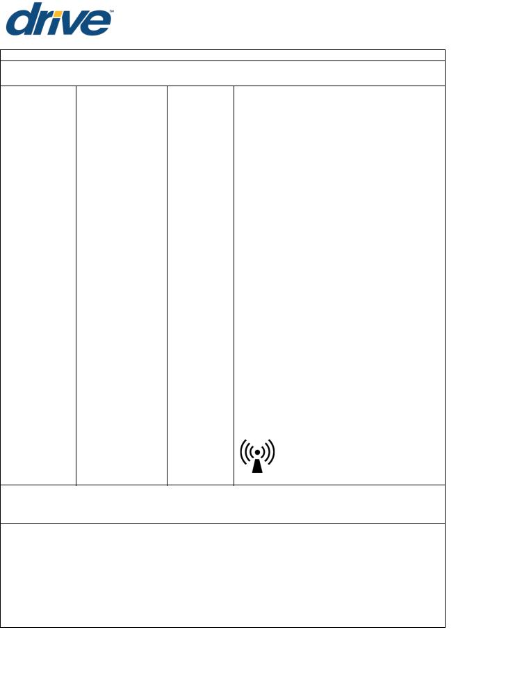
DECLARATION - ELECTROMAGNETIC EMISSIONS
Guidance and manufacturer's declaration - Electromagnetic emissions
The Prime Care™P703 is intended for use in the electromagnetic environment specified below. The customer or the user of the Prime Care™P703 should ensure that it is used in such an environment.
Emissions Test |
Compliance |
Electromagnetic environment - Guidance |
|
|
|
|
|
RF Emissions CISPR 11 |
Group 1 |
The Prime Care™P703 uses RF energy only for its |
|
internal function. Therefore, its RF emissions are |
|||
|
|
||
|
|
very low and are not likely to cause any |
|
RF Emissions |
|
||
Class B |
interference in nearby electronic equipment. |
||
CISPR 11 |
|
||
|
|
||
|
|
|
|
|
|
The Prime Care™P703 is suitable for use in all |
|
Harmonic Emissions |
|
establishments including domestic |
|
Class A |
establishments and those directly connected to |
||
IEC 61000-3-2 |
|||
|
the public power supply network that supplies |
||
|
|
||
|
|
buildings used for domestic purposes. |
|
|
|
The Prime Care™P703 is not suitable for |
|
RF emissions |
Complies |
interconnection with other equipment. |
|
CISPR 14-1 |
|
||
|
|
||
|
|
|
|
RF emissions |
Complies |
|
|
CISPR 15 |
|
||
|
|
||
|
|
|
The information in this document is subject to change without notice.
Page 10

P703 Owner's Manual| REV 001
Dec 1st, 2017
Recommended separation distances between portable and mobile
RF communications equipment and the Prime Care™P703
The Prime Care™P703 is intended for use in the electromagnetic environment in which radiated RF disturbances are controlled. The customer or the user of the Prime Care™P703 can help prevent electromagnetic interference by maintaining a minimum distance between portable and mobile RF communications equipment (transmitters) and the Prime Care™P703 as recommended below, according to the maximum output power of the communications equipment.
Rated maximum output power |
Separation distance according to frequency of transmitter |
|||||||||
|
|
|
m |
|
|
|
||||
of transmitter |
|
|
|
|
|
|
||||
|
|
|
|
|
|
|
|
|
||
150 kHz to 80 MHz |
80 MHz to 800 MHz |
800 MHz to 2,5 GHz |
||||||||
W |
||||||||||
|
|
|
|
|
|
|
|
|
||
( √ ) |
( √ ) |
( √ ) |
||||||||
|
||||||||||
0.01 |
0.12 |
|
|
0.12 |
|
|
0.23 |
|
|
|
|
|
|
|
|
|
|
|
|
|
|
0.1 |
0.38 |
|
|
0.38 |
|
|
0.73 |
|
|
|
|
|
|
|
|
|
|
|
|
|
|
1 |
1.2 |
|
|
1.2 |
|
|
2.3 |
|
|
|
|
|
|
|
|
|
|
|
|
|
|
0.1 |
0.38 |
|
|
0.38 |
|
|
0.73 |
|
|
|
|
|
|
|
|
|
|
|
|
|
|
10 |
3.8 |
|
|
3.8 |
|
|
7.3 |
|
|
|
|
|
|
|
|
|
|
|
|
|
|
100 |
12 |
|
|
12 |
|
|
23 |
|
|
|
|
|
|
|
|
|
|
|
|
|
|
For transmitters rated at a maximum output power not listed above, the recommended separation distance d in meters (m) can be estimated using the equation applicable to the frequency of the transmitter, where P is the maximum output power rating of the transmitter in watts (W) accordable to the transmitter manufacturer.
NOTE: I At 80 MHz and 800 MHz the separation distance for the higher frequency range applies
NOTE: 2 These guidelines may not apply in all situations. Electromagnetic propagation is affected by absorption and reflection from structures, objects and people.
Page 11
The information in this document is subject to change without notice.
P703 Owner's Manual| REV 001
Dec 1st, 2017
Guidance and manufacturer's declaration: Electromagnetic Immunity
The Prime Care™P703 is intended for use in the electromagnetic environment specified below. The customer or the user of the Prime Care™P703 should ensure that it is used in such an environment.
Immunity test IEC 60601 test |
Compliance Electromagnetic environment - guidance |
level |
level |
|
|
|
Portable and mobile RF communications |
|
equipment should be used no closer to any |
|
part of the Prime Care™P703, including |
|
cables, than the recommended separation |
|
distance calculated from the equation |
|
applicable to the frequency of the |
|
transmitter. |
|
|
|
Recommended separation distance |
|||||||||||
|
|
|
|
|
|
|
|
|
|
|
|
|
|
|
Conducted |
|
|
|
|
|
|
|
( |
|
√ ) |
||||
|
|
|
|
|
|
|
|
|||||||
|
|
|
|
|
|
|
|
|
|
|
|
|
|
|
RF |
3 Vrms |
|
|
|
|
|
|
|
|
|
||||
|
( |
|
|
√ |
|
) 80MHz to 800MHz |
||||||||
|
|
|
||||||||||||
IEC 61000-4-6 |
150 kHz to 80 MHz |
10 V |
|
|
|
|
|
|
|
|
|
|
|
|
( |
|
|
√ |
) 800MHz to 2,5GHz |
||||||||||
|
|
|
|
|
||||||||||
|
|
|
|
|
||||||||||
|
|
|
Where P is the maximum output power |
|||||||||||
Radiated RF |
3 V/m |
10 V/m |
rating of the transmitter in watts (W) |
|||||||||||
IEC |
80 MHz to 2.5 GHz |
|
according to the Transmitter manufacturer |
|||||||||||
61000-4-3 |
|
|
and d is the recommended separation |
|||||||||||
|
|
|
distance in meters (m). Field strengths from |
|||||||||||
|
|
|
fixed RF transmitters, as determined by an |
|||||||||||
|
|
|
electromagnetic site survey, a should be less |
|||||||||||
|
|
|
than the compliance level in each |
|||||||||||
|
|
|
frequency range.b |
|||||||||||
|
|
|
Interference may occur in the vicinity of |
|||||||||||
|
|
|
equipment marked with the following |
|||||||||||
|
|
|
symbol: |
|
|
|
|
|
|
|
||||
NOTE: I At 80MHz and 800MHz the higher frequency range applies.
NOTE: 2 These guidelines may not apply in all situations. Electromagnetic propagation is affected by absorption and reflection from structures, objects and people.
aField strengths from fixed transmitters, such as base stations for radio (cellular/cordless) telephones and land mobile radios, amateur radio, AM and FM radio broadcast and TV broadcast cannot be predicted theoretically with accuracy. To assess the electromagnetic environment due to fixed RF transmitters, an electromagnetic site survey should be considered. If the measured field strength in the location in which the Prime Care™P703 is used exceeds the applicable RF compliance level above, the Prime Care™ P703 should be observed to verify normal operation. If abnormal performance is observed, additional measures may be necessary, such as reorienting or relocating the Prime Care™ P703.
bOver the frequency range 150 kHz to 80 MHz, field strengths should be less than 10 V/m.
The information in this document is subject to change without notice.
Page 12

P703 Owner's Manual| REV 001
Dec 1st, 2017
FEATURES AND ACCESSORIES
Standard Features
76’’,80”, and 84” adjustable sleep surface
Height adjustable from 7” to 30”.
Synchronized control system.
Roll-at-any-Height design
Floor Lock System: Foot Pad Lock Mechanism
Welded Tubular Steel Frame
Slat Sleep Deck
Wall Guard
IV Pole Holders
Heavy Duty 3” Dual Footprint Casters
Adjustable Mattress Retainers
Heel Lift Ratchet
Soft Grey Frame
Under bed light
Accessories and Options
Pressure Reduction Mattress
Air Flotation Mattress
Cushion Fall Mat
Assorted Bed End styles & colors
39”-42” Integrated width extension
Staff Control Panel
Rotating Assist Rails &Bars
Deluxe Rotating Assist Rails
Battery Back-Up
Trapeze Assembly
Bed Transporter System
88" Length Extension
 WARNING
Incompatible mattress and rotating assist bars/rails can create hazards. Read instructions for use.
Bed Serial Numbers
When ordering parts or when contacting Drive DeVilbiss Healthcare Customer Service Department, please include bed's model and serial numbers, found on the identification labels as below. The identification labels are located under the sleep deck on the either side of the bed frame.
Page 13
The information in this document is subject to change without notice.
P703 Owner's Manual| REV 001
Dec 1st, 2017
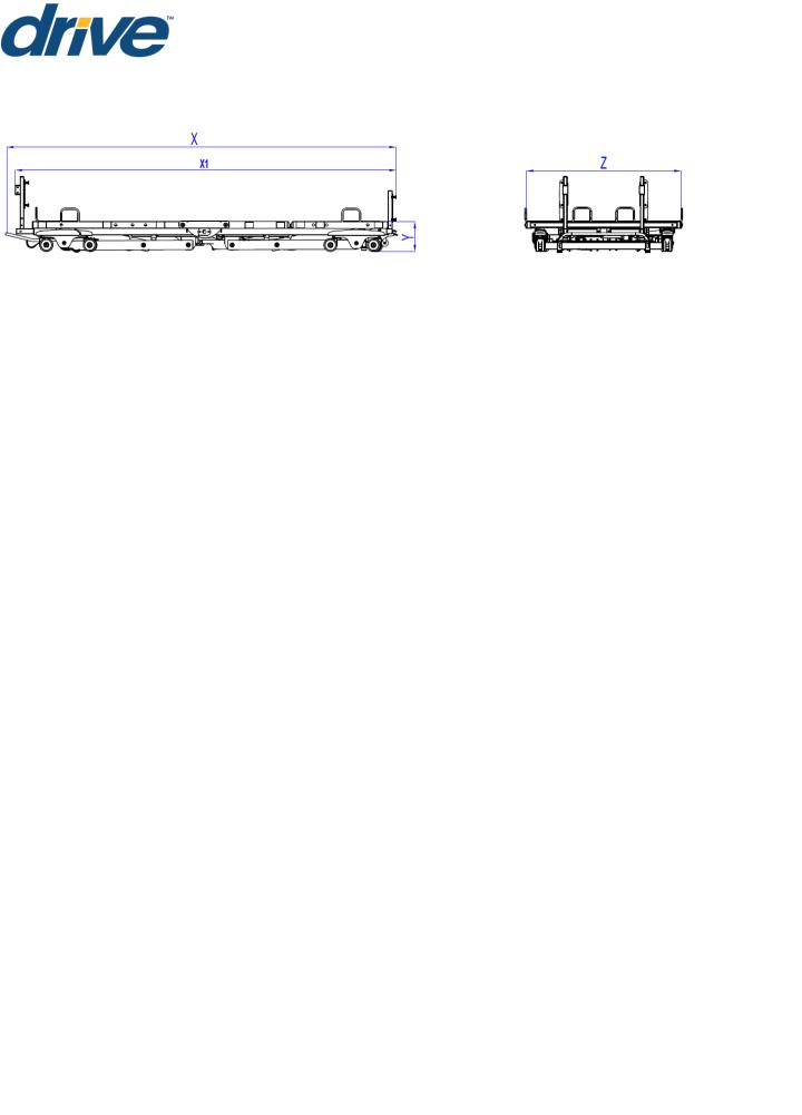
TECHNICAL SPECIFICATIONS
ITEM |
|
SPECIFICATION |
|
Overall Length (with wall bumper) (X) |
89”,93”,97”,101” |
227cm,237cm,247cm,257cm |
|
Overall Length (without wall bumper) (X1) |
83”,87”,91”,95” |
212cm,220cm,230cm,240cm |
|
Bed height range (Y) |
7” to 30” |
|
17.8cm to 76.2cm |
Overall Width without width extension* (Z) |
36” |
|
91.4cm |
Overall Width with width extension Z |
39” or 42” |
|
99cm” to 107cm |
Length of Mattress Deck |
76” |
|
1934cm |
Mattress Thickness Range |
5.5" to 7" |
|
14cm to 18cm |
Mattress Lengths without length extension |
76”, 80”, 84”, |
|
193cm,203cm, 213cm |
Mattress Lengths with length extension |
88” |
|
223.5cm |
Mattress Width |
36" , 39” ,42" |
|
91.5cm,99cm, 107cm |
Weight of Bed without H/F boards or |
215.8 lbs |
|
98.1kg |
accessories |
|
||
|
|
|
|
Maximum Weight Capacity (SWL)** |
500 lbs |
|
227 kg |
Maximum User’s Weight |
475 lbs |
|
215kg |
Head Deck Angle Range |
|
|
0°to 65° |
Thigh Deck Angle Range |
|
|
0°to 32° |
Foot Deck Angle Range |
|
|
0°to 11° |
Input Voltage*** |
100-240 VAC, 50/60 Hz |
||
Protective Earth Ground |
|
|
CLASS II |
Electrical Shock Protection |
|
|
TYPE B |
Enclosure Protection |
|
|
IP54 |
Duty cycle |
Min. 2min (on)/ Max. 18min (off) |
||
NOTE: All length and height measurements ± .75”, Angle measurements ± 3°
* Rotating Assist Bar/Rails add 3” (7.5cm) to each side of the bed
**SWL includes the weight of the resident/patient and all other accessories including, but not limited to mattresses, head/footboards, rotating assist bars, etc.
***Means of isolating equipment from supply mains:
This bed may be isolated from the supply mains by unplugging the mains cable (power cord) from the wall outlet.
The information in this document is subject to change without notice.
Page 14

P703 Owner's Manual| REV 001
Dec 1st, 2017
COMPLIANCE INFORMATION
Matching the correct bed components to meet regulatory specifications can be complicated. Drive DeVilbiss Healthcare offers a wide variety of compliance options and we can assist your facility in selecting components or accessories that are recommended for the specific bed model.
General information
The recommended environment for operation and storage/transportation of the bed is listed below:
|
Operation |
Storage/Transportation |
Ambient temperature: |
10°C ~ 36°C (50°F~96.8°F) |
-10°C ~ 50°C (14°F~122°F) |
Relative humidity range: |
30% ~ 75% |
20% ~ 95% |
Atmospheric pressure: |
86KPa~ 106Kpa |
70KPa~ 106KPa |
This bed is classified for intermittent operation. Bed may be operated for 2 minutes out of every 20 minutes.
Applied Parts List
Bed Frame
Head/ Foot Board
Rotating Assist Bars/ Rails
Mattress Retainer
Width Extension
Pendant
Trapeze
Staff control panel
Length Extension
Materials accessible to user
Surface Coating: Powder Coating
Color of Powder: Carbon black, Ethylene Bis-Stearamide, Solvent Red
Pendant Housing: ABS
Staff control panel housing: ABS
Plastic Cover of Rail/Bar: PU
Head/Foot Board: Wood
Trapeze: Nylon webbing
Page 15
The information in this document is subject to change without notice.

P703 Owner's Manual| REV 001
Dec 1st, 2017
UNPACKING INSTRUCTIONS
TOOLS REQUIRED
Pliers or Wire Cutters |
Utility Knife |
 CAUTION
Unpack the bed in an area with sufficient room to work. Do not allow residents/patients near the bed until it has been completely set up and the work area has been cleared of all debris.
1.Inspect the bed for shipping damage. If the bed is damaged. Do not use bed and immediately contact Drive DeVilbiss Healthcare for further instruction.
2.Verify the proper bed model was shipped. If you feel there was a mistake. Do not use bed and immediately contact Drive DeVilbiss Healthcare for further instruction.
3.After verifying you’ve received the correct device without damage, cut black strapping around box and remove enclosing bed frame.
NOTE: If the carton is in an upright position, slowly lower to the floor. It may be necessary for two or more people to help in lowering the bed.
4.Cut zip ties to remove wall guard at the head of the bed.
5.Cut the zip ties to remove mattress retainers on each side of the bed.
6.Remove ties from pendant.
7.Remove any remaining zip ties or foam left on bed frame.
NOTE: Damage to the equipment may occur if the zip ties are removed incorrectly.
 CAUTION
DO NOT remove zip ties that are holding cords underneath bed frame.
INITIAL INSPECTION
1.Inspection of All Components - Receipt of assembled bed.
2.Check bed components for obvious damage.
3.Inspect power supply cords for cuts and/or damage.
4.Check that actuator cords are connected properly to the controller.
5.Locate power cord and plug into grounded 100-240VAC outlet.
6.Raise the bed frame and check to make sure everything is plugged into the control box and no wires are loose. If wires are not in control box. Do not use bed and immediately contact Drive DeVilbiss Healthcare for further instruction.
The information in this document is subject to change without notice.
Page 16
 Loading...