

Page 1
www.drivemedical.co.uk
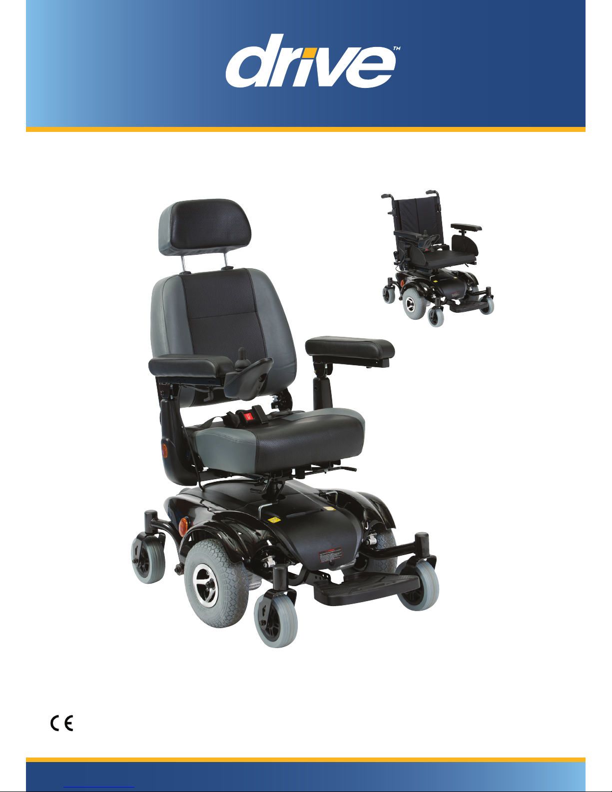
Seren Powerchair
User Manual
Page 2

SEREN
TABLE OF CONTENTS
INTRODUCTION
IMPORTANT PRECAUTIONS
ELECTROMAGNETIC INTERFERENCE AND WARNINGS
IDENTIFICATION OF PARTS
OPERATING YOUR POWER CHAIR
DISASSEMBLING / RE-ASSEMBLING YOUR POWER CHAIR
CHARGING THE BATTERIES
CARE
AND MAINTENANCE
TROUBLESHOOTING
TECHNICAL SPECIFICATIONS
---------------------------------------------------------1
------------------------------------------2
-------3
------------------------------------------5
---------------------------------8
-12
----------------------------------------14
------------------------------------------16
-------------------------------------------------18
--------------------------------------20
Instruction Booklet
Page 3

SEREN
Information of European Representative :
EMERGO EUROPE
Molenstraat 15
2513 BH, The Hague
The Netherlands
If you have any question, please contact your local dealer or:
INTRODUCTION
1
Thank you and congratulation on purchasing your new 'ULYH Power Chair. It is
designed to provide you with transportation ability indoors and outdoors.
We pride ourselves on providing safe and comfortable products. Our goal is to ensure
your complete satisfaction with our product. We are certain that you will enjoy your
Drive Medical power chair.
Please read and observe all warning and instruction provided in owner's manual before
operating with this power chair. Also, retain this booklet for future reference.
Instruction Booklet
Page 4

SEREN
IMPORTANT PRECAUTIONS
2
•Only one person at a time can ride a Drive Medical Power Chair.
•Maximum load is 136 kg/300 lbs.
•Turn off power before getting on or off your power chair.
•
Always drive carefully with your feet on the footplate and be aware of others in your area.
•Always use pedestrian crossings wherever possible. Take extreme when care crossing
roads.
•Do not drive on slopes exceeding 6 degrees, and take extreme care when turning on
slopes.
•Do not use full power when turning to sharp corners.
•Take great care and drive in low speeds when backing up, riding downhill, or on uneven
surfaces
and climbing curb.
•The power chair may not operate well in high humidity.
•Never put your power chair in neutral when staying on slopes.
•Follow all traffic laws when riding in the vicinity of public roads.
•It is NOT recommended to use your power chair in wet environments as it may cause
damage.
Instruction Booklet
Page 5
SEREN
ELECTROMAGNETIC INTERFERENCE
AND WARNINGS
3
CAUTION: It is very important that you read this information regarding the possible
effects of Electromagnetic Interference on your power chair.
Powered wheelchairs and motorized scooters may be susceptible to electromagnetic
interference (EMI), which is interfering electromagnetic energy (EM) emitted from sources
such a radio stations, TV stations, amateur radio (HAM) transmitters, two-way radios, and
cellular phones. The interference (from radio wave sources) can cause the motorized
scooter to release its brakes, move by itself, or move in unintended directions. It can also
permanently damage the motorized scooter control system. The intensity of the interfering
EM energy can be measured in volts per meter (V/m). Each motorized scooter can resist
EMI up to a certain intensity. This is called its "immunity level." The higher the immunity
level, the greater the protection will be. At this time, current technology is capable of
achieving at least a 20 V/m immunity level, which would provide useful protection from
the more common sources of radiated EMI. The immunity level of this motorized scooter
model is 20 V/m.
There are a number of sources of relatively intense electromagnetic fields in the everyday
environment. Some of these sources are obvious and easy to avoid. Others are not
apparent and exposure is unavoidable. However, we believe that by following the warnings
listed below, your risk to EMI will be minimized.
Some cellular telephones and similar devices transmit signals while
they are ON, even when not being used.
The sources of radiated EMI can be broadly classified into three types:
1.Hand-held portable transceivers (transmitters-receivers) with the antenna mounted
directly on the transmitting unit. Examples include: citizens band (CB) radios, "walkie
talkie," security, fire, and police transceivers, cellular telephones, and other personal
communication devices.
2.Medium-range mobile transceivers, such as those used in police cars, fire trucks,
ambulances, and taxis. These usually have the antenna mounted on the outside of
the vehicle.
Instruction Booklet
Page 6
SEREN
4
3.Long-range transmitters and transceivers such as commercial broadcast transmitters
(radio and TV broadcast antenna towers) and amateur (HAM) radios.
Because EM energy rapidly becomes more intense as one moves closer to the transmitting
antenna (source), the EM fields from hand-held radio wave sources (transceivers) are of
special concern. It is possible to unintentionally bring high levels of EM energy very close
to the power chair control system while using these devices. This can affect power chair
movement and braking. Therefore, the warnings listed below are recommended to prevent
p
ossible interference with the control system of the power chair
.
Other types of hand-held devices, such as cordless phones, laptop computers,
AM/FM radios, TV sets, CD players, and cassette players, and small appliances,
such as electric shavers and hair dryers, so far as we know, are not likely to
cause EMI problems to your motorized scooter.
Power Chair Electromagnetic Interference:
Electromagnetic interference (EMI) from sources such as radio and TV stations, amateur
radio (HAM) transmitters, two-way radios, and cellular phones can affect the power chair.
Following the warnings listed below should reduce the chance of unintended brake release
or power chair movement, which could result in serious injury.
1.Do not operate hand-held transceivers (transmitters-receivers), such as citizens band
(CB) radios, or turn ON personal communication devices, such as cellular phones,
while the power chair is turned ON;
2.Be aware of nearby transmitters, such as radio or TV stations, and try to avoid coming
close to them;
3.If unintended movement or brake release occurs, turn the power chair OFF as soon
as it is safe;
4.Be aware that adding accessories or components, or modifying the power chair, may
make it more susceptible to EMI; and
5.Report all incidents of unintended movement or brake release to the distributor listed
on the inside front cover of this manual. Note whether there is a source of EMI nearby.
Warnings:
Important Information
1.20 volts per meter (V/m) is a generally achievable and useful immunity level against EMI
(as of May 1994). The higher the level, the greater the protection.
2.The immunity level of this product is 20 V/m.
Instruction Booklet
Page 7
SEREN
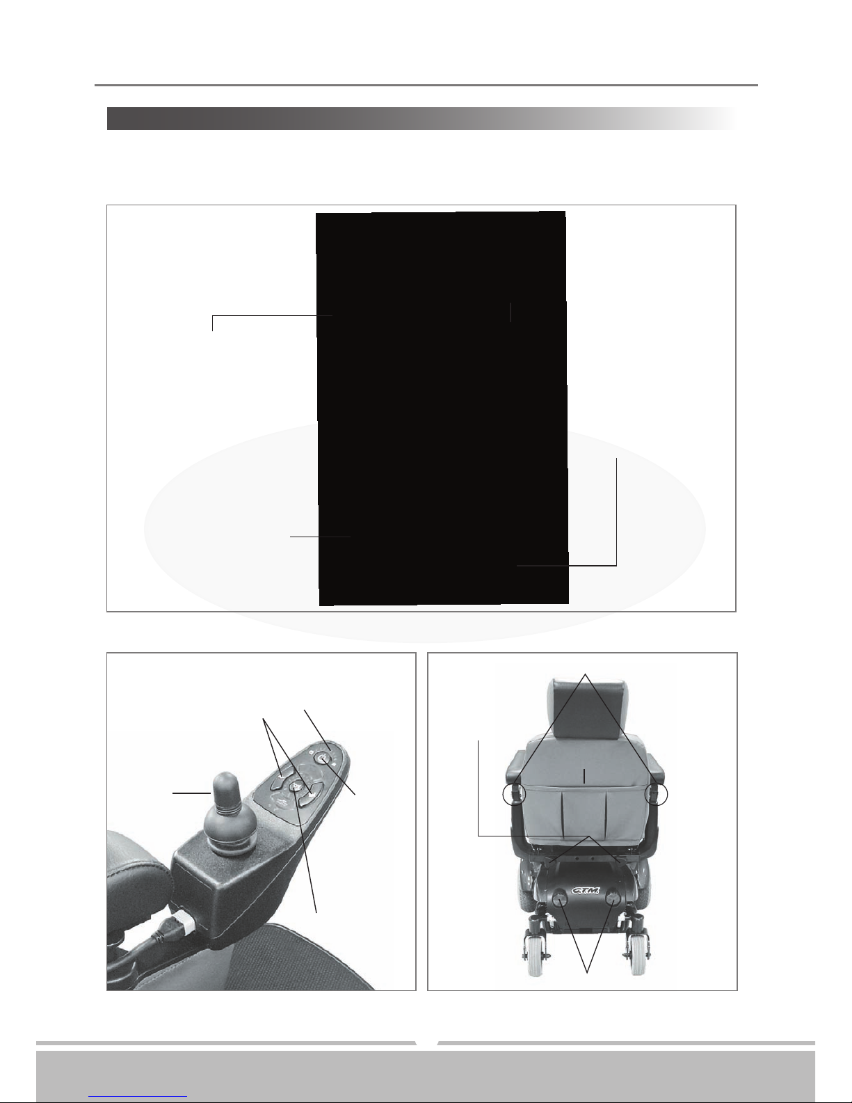
On/Off
Button
Horn
Joystick
Speed Control Button
Self Diagnostic
Warning Lights &
Battery Gauge
Rear Bag
Armrest width
Adjustment
Thumbscrews
Armrest height Adjustment Thumbscrews
Rear Reflectors
Figure 1 - Seren Power Chair Front View
Figure 2 - Seren Joystick
Figure 3 - Seren Power Chair Rear View
IDENTIFICATION OF PARTS
5
Before attempting to drive this power chair on your own, it is important that you familiarize
yourself with the controls and how they operate.
19" Mid-Back Seat
w/ Adj. Headrest & Seat Belt
Width & Height
Adjustable Armrests
Extended Footplate
with 3-Angle Adjustment
10"
Drive Wheels
Instruction Booklet
Page 8
6
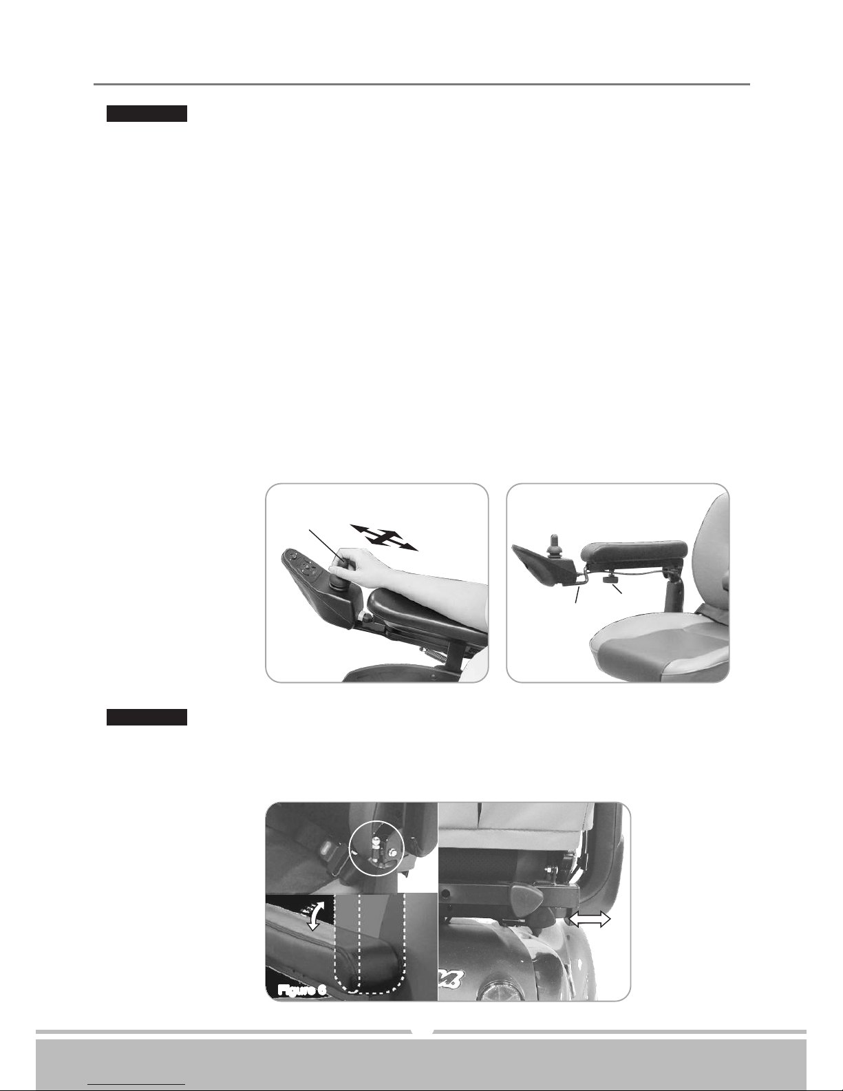
JOYSTICK:
•Self Diagnostic Warning Lights
Flashing of lights indicates there is a problem within power chair. See page 18 for more
information.
•Battery Gauge
There are eleven LED lights on joystick. When all LED lights are on, batteries are
fully charged; The Battery Gauge is used to indicate power on and provides an estimate
of the remaining battery capacity.
Any green LEDs lit indicate well charged batteries.
If only amber and red LEDs are lit, the batteries are moderately charged. Recharge
before undertaking a long trip.
If only red LEDs are lit, the batteries are running out of charge. Recharge as soon as
possible.
•Extendable Bracket
By releasing Knob (B) the joystick bracket (C) is able to extend and retract. With joystick
retracted, this enables you to pull up to any table, and tighten knob (B), when adjusted
to a comfortasle position.
ARMREST:
•Armrest width & height Adjustment Thumbscrews
Loosen two thumbscrews to adjust armrest width & height tighten again to lock in
desired position.
Figure 4 Figure 5
Figure 6
(A)
(C)
(B)
SEREN
Instruction Booklet
Page 9
SEREN
7
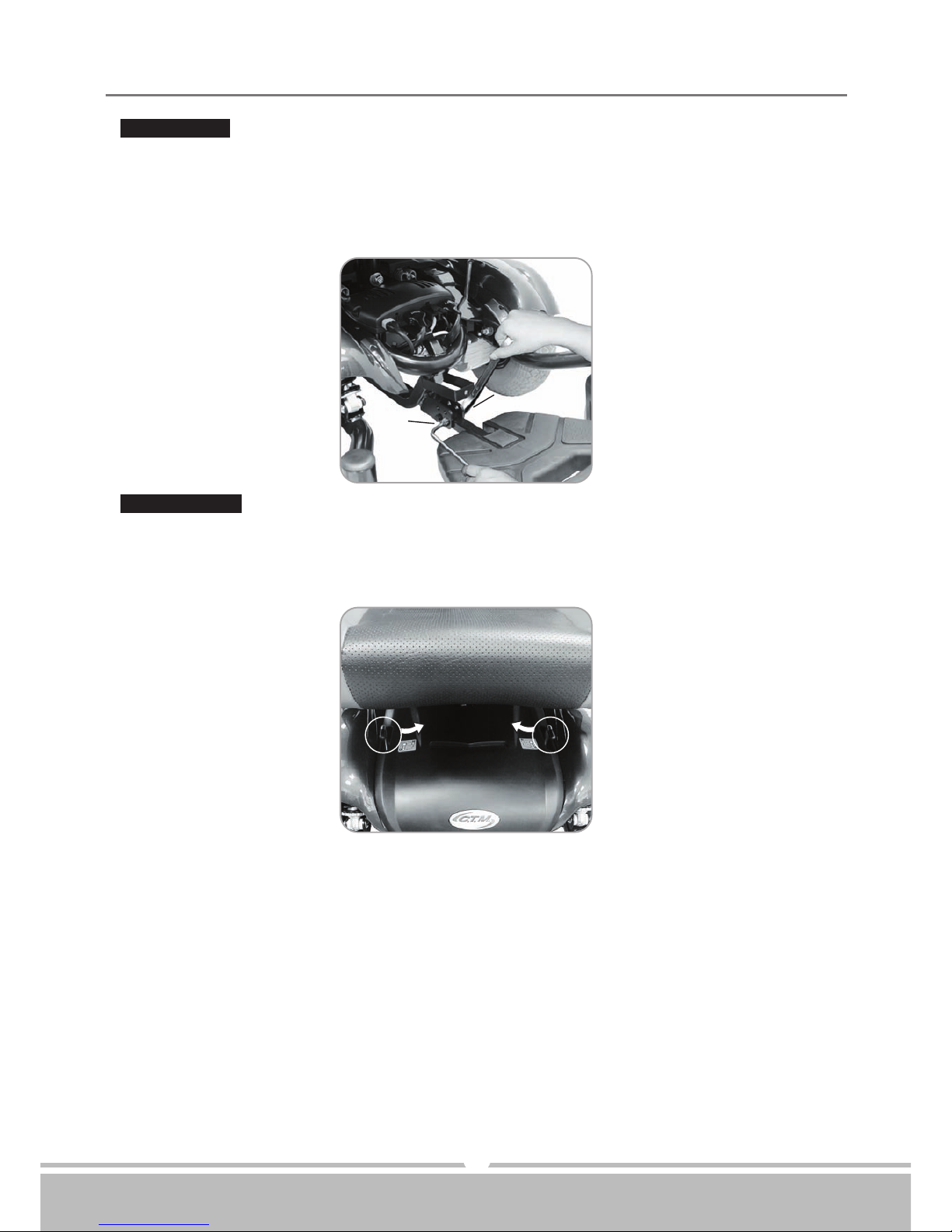
FOOTPLATE:
•Footplate
The footplate can be adjusted according to your specific needs. It can be width &
adjusted vertically or horizontally. To adjust footplate, loosen screw and arrange height
to desired position, then, tightened screw to secure plate in place. (D & E)
Figure 7Figure 7
POWER BASE:
•Free-Wheeling Lever
When lever is in N (Neutral) position, power chair can be moved manually.
When lever is in D (Drive) position, power chair can be driven. Normal position is D.
Figure 8Figure 8
(D)
(E)
Instruction Booklet
Page 10
SEREN
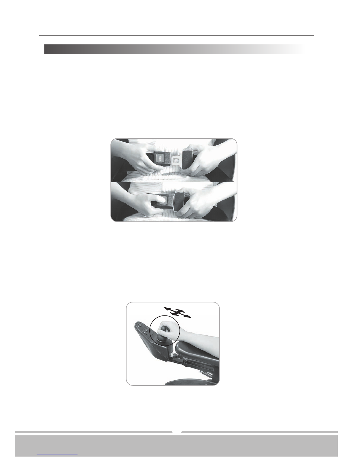
Figure 9Figure 9
Figure 10Figure 10
OPERATING YOUR SCOOTER
8
Before beginning your journey with your new power chair, make sure power chair is on
a level surface and clear of any obstacle. Although your power chair is able to climb slopes,
it is safer to practice on a leveled surface.
1.Before operating with your power chair, check the following:
•free-wheeling lever is on D.
•speed dial is at the lowest speed (fully turned counterclockwise).
2.Sit on chair and fasten seat belt.
3.When power is turned on, all battery gauge LED lights should be lit lighting. The self-
diagnostic warning lights should not be blinking.
4.While resting your arm on armrests, joystick should be within reach. By pushing joystick
slightly forward, power chair will move forward slowly, and pushing joystick fully forward,
chair will move at normal speed. And adjusting speed dial will also decrease or increase
speed. Also, with joystick, you are able to turn chair in 360
o
. When joystick is let go and
back in center position, chair will stop.
5.Practice driving where there is no obstacle. Start at slowest speed and move forward
and backward; make some turns. As you get more comfortable, you can increase the
speed by turning speed dial knob clockwise.
(F)
(G)
(H)
Instruction Booklet
Page 11
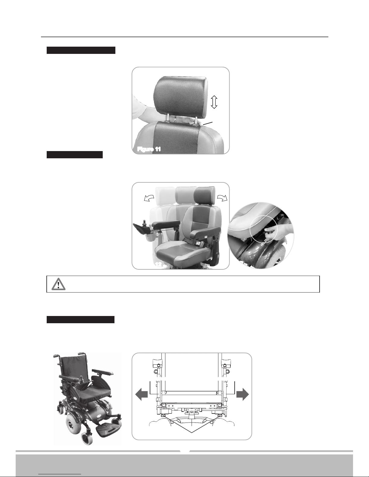
Figure 11
Figure 12
9
Headrest Adjustment:
Seat Adjustment:
By pressing (k) to adjust the headrest (J) up & down to a comfortable position.
By lifting up lever (L) to rotate seat (See Fig. 12)
Note: Do not swivel seat angle over 90 degrees, to prevent wires twist.
While standing up, avoid stepping on footplate as it may cause injury.
The batteries should be charged as soon as possible after each ride. See CHARGING
THE BATTERIES on page 14.
(J)
(L)
Figure 13
Front View
Right Armrest Bracket
Knob
Left Armrest Bracket
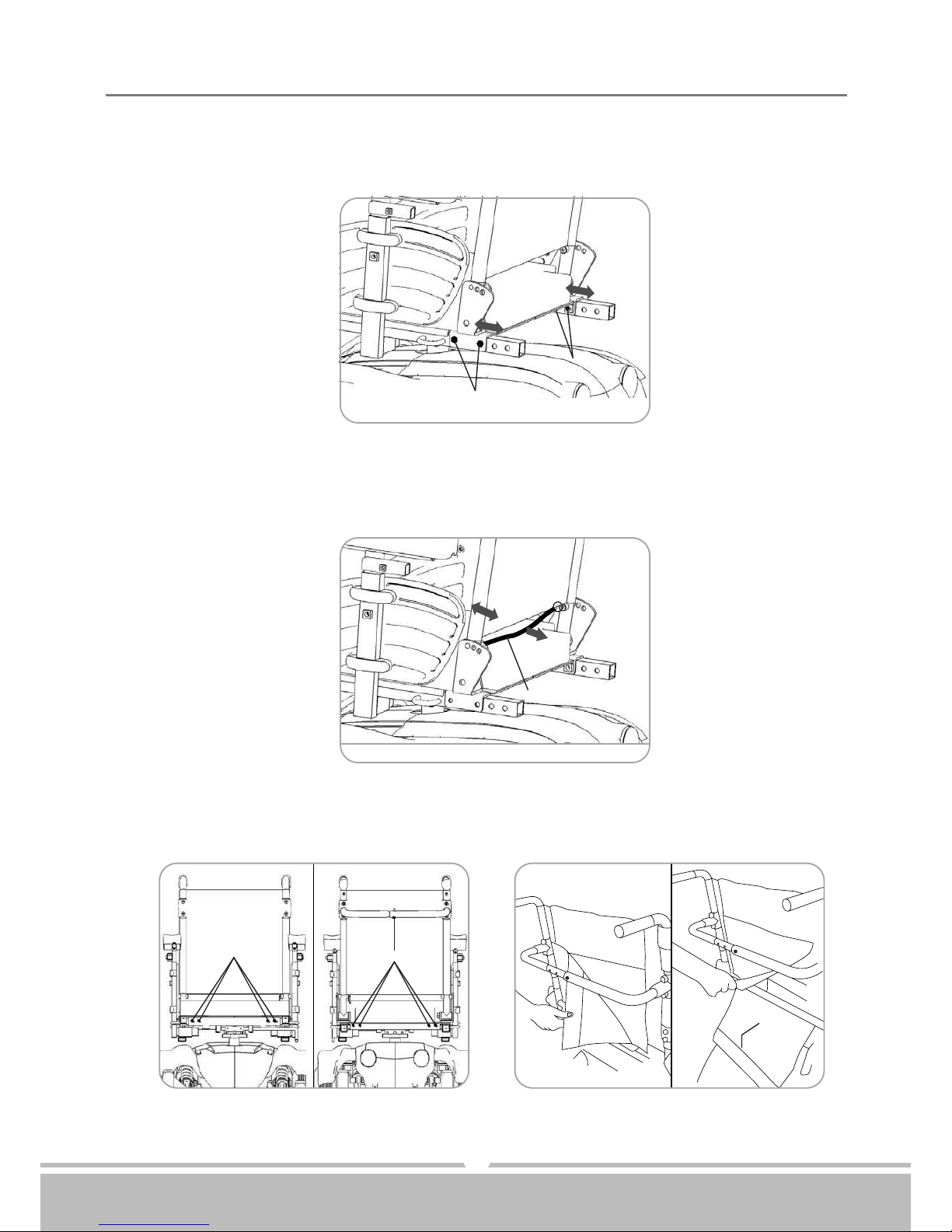
Optional Seat (A~D):
(A). Armrests' Width Adjustment
By releasing both sides knobs, and adjust armrests to a comfortable position, then
tighten with knobs.
(K)
SEREN
Instruction Booklet
Page 12
SEREN
10
Figure 14Figure 14
Fixation ScrewFixation Screw
Fixation ScrewFixation Screw
(B). Seat's Depth Adjustment
By releasing fixation screws from back sides, and adjust to a comfortable position,
then tighten with fixation screws.
Figure 15Figure 15
Fixation Vel-croFixation Vel-cro
(C). Backrest Angle Adjustment
By pulling the fixation vel-cro backwards to disengage the pins from the holes, and
adjust angle to a comfortable position, then release fixation vel-cro to engage to it's
position.
Figure 17Figure 17
Backrest PadBackrest Pad
Figure 16Figure 16
Front ViewFront View
Fixation ScrewFixation Screw
Fixation ScrewFixation Screw
Rear ViewRear View
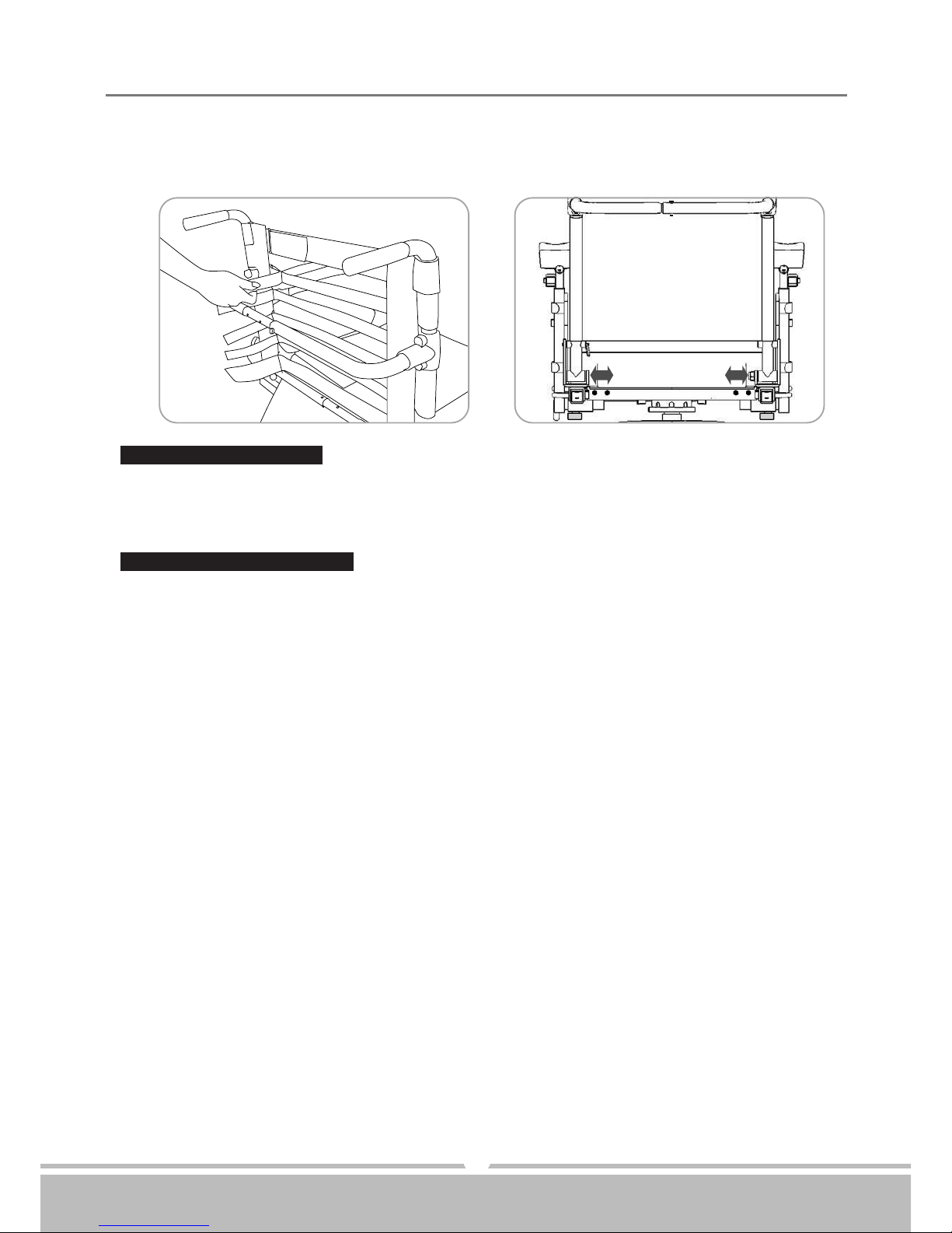
(D). Seat's Width Adjustment
1.By taking front&rear and support brace's fixation screws(9pcs) off.
2.Take off backrest pad by release it's vel-cro.
Instruction Booklet
Page 13
SEREN
Other Operating Information:
Hill climbing : You may need to use a higher speed. For a higher speed, turn speed dial
clockwise.
Down slopes :
Proceed with dawnward slope slowly, and turn speed dial counterclockwise.
This enables good control when speed is set in slower motion. However,
your power chair will not self accelerate down hills due to. automatic
braking, taking effect should you attempt to drive too fast.
Curb climbing :
Approach slowly from right angles to the curb. A direct approach is
needed. Do not attempt greater than a 2" curb.
If Self-Diagnostic Warning Lights start to flash, identify problem from chart on page 18
and take action.
If power chair breaks down and must be moved, please follow below directions :
1.Get off power chair.
2.Push free-wheeling lever to N.
3.Move power chair slowly to a safe location.
4.Push free-wheeling lever back to D.
11
Keep in mind these rules:
•Use your power chair only where it is safe for walking.
•
Drive in low speed when reversing, riding downhill on ramp or curb or on uneven surface.
3.Release all backrest's vel-cro straps.
4.
Adjust frame to a comfortable width position and adjust vel-cro to appropriate tightness,
then put backrest pad back, complete by tighten 9pcs of width fixation screws.
Figure 19Figure 19
Rear ViewRear View
Figure 18Figure 18
Instruction Booklet
Page 14
SEREN
12
DISASSEMBLING / RE-ASSEMBLING
YOUR POWER CHAIR
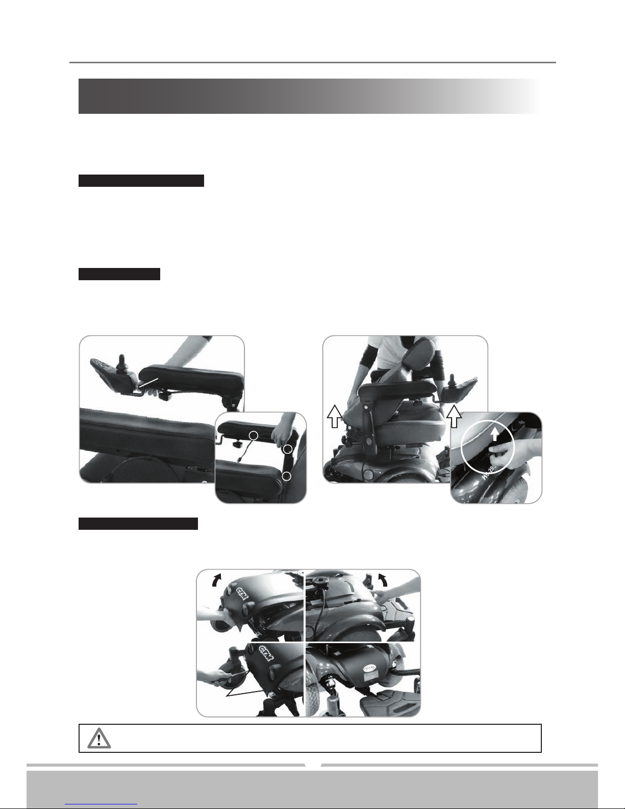
Joystick Cable Removal:
Please follow instructions below to remove joystick cable (M) from armrest.
1.Unplug joystick cable (See Fig. 20).
2.Press lock pins underneath front and along seat sides to unlock, then lift chair up to
remove (See Fig. 21) Joystick cable is tied up by 3 cord clips on armrest (See white circle).
Remove cable from armrest.
Seat Removal:
1.Fold down seat back.
2.
Pull up the seat lock lever (N).
3.Lift up on seat assembly (O) to ensure the seat is secure
(See Fig. 14).
Body Shroud Removal:
By using a screw driver to pressing down at the center of the push rivet, to
release the shroud.
1. Remove 3 push rivets (P1) from both front shroud (P) and rear shroud (P2).
2. Follow the arrow's direction to lift up shrouds (See Fig. 22).
Taking apart your power chair enables you to save space when keeping it in storage or
carrying it along in your vehicle. Having power chair disassembled is easier than ever
since no tools are required.
Figure 20Figure 20 Figure 21Figure 21
(O)
(M)
(N)
Figure 22Figure 22
(P1)
(P1)
(P2)
(P)
Instruction Booklet
Page 15
SEREN
Be careful when carry the batteries as they are heavy.
DO NOT connect the Positive (+) to the Negative (-) battery terminal by any
conductive metals.
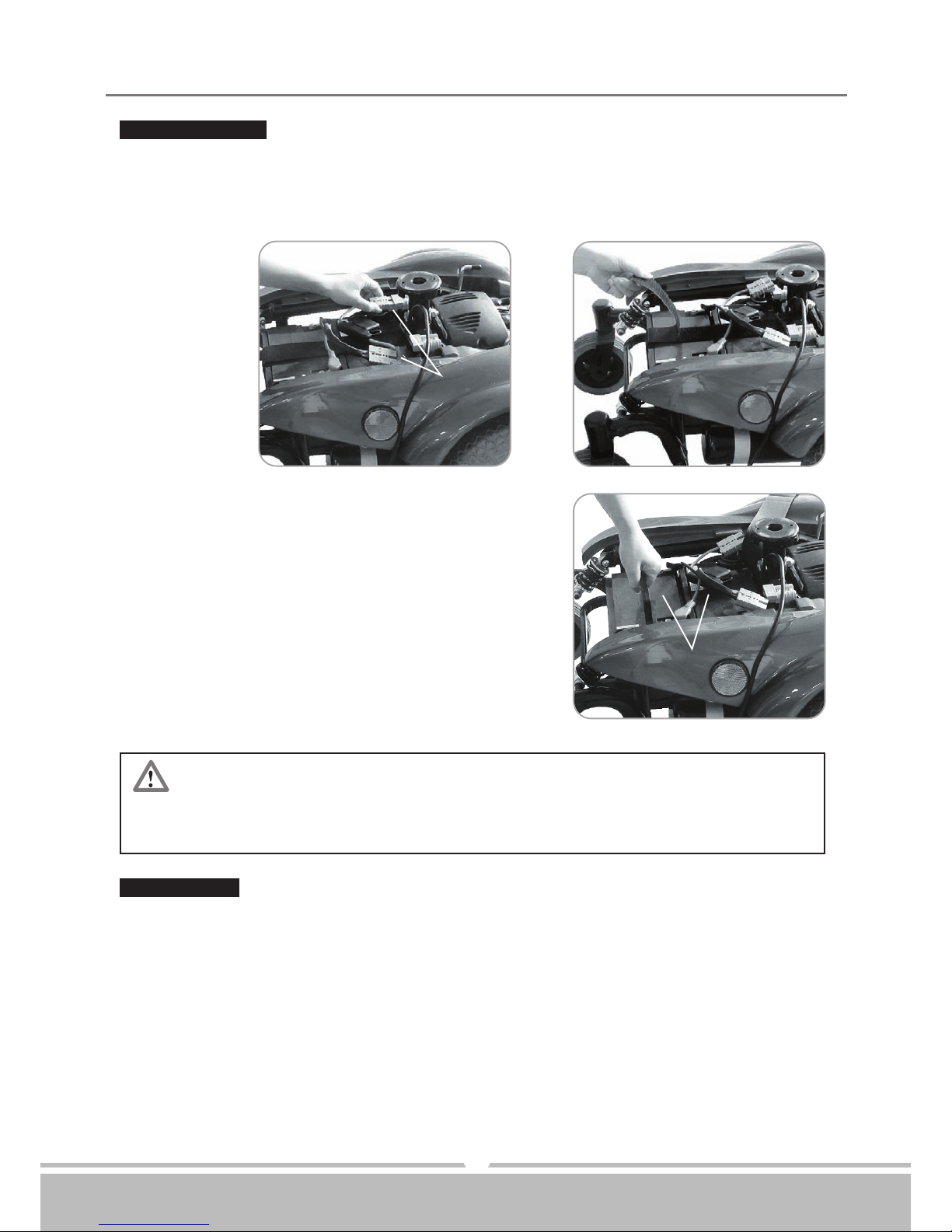
Battery Removal:
1.Disconnect two battery plugs (Q) (See Fig. 23).
2.Unfasten velcro strap that hold batteries in place
(See Fig. 24).
3.Remove two batteries (S)
(See Fig. 25).
13
Figure 23Figure 23
Figure 24Figure 24
Figure 25Figure 25
(Q)
(R)
(S)
Re-assemble:
To re-assemble your power chair, you can repeat disassembly directions in reverse.
Instruction Booklet
Page 16
SEREN
14
CHARGING THE BATTERIES
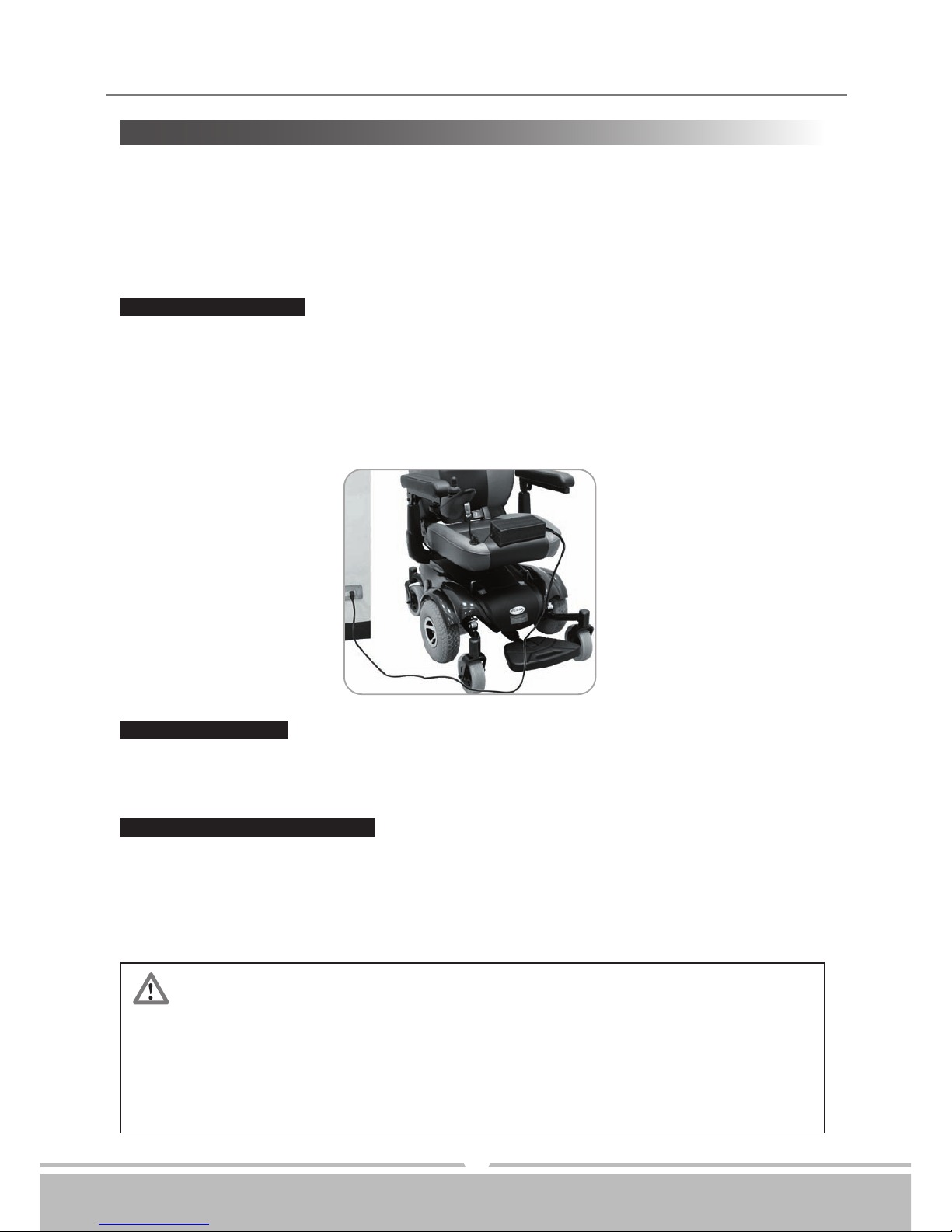
Your Drive power chair is equipped with two, service free 12V 36Ah rechargeable
batteries and one 24V/5A off-board charger. Batteries must be charged before using
power chair for the first time and it is recommended to be charged up to 8 - 14 hours
after each day's use. Be sure power switch is in OFF position and free-wheeling
lever is in "D" position.
1.Position Seren power chair next to a standard wall outlet.
2.Insert the the battery charger cord into the chair input battery charging socket, which
is located on the frout of the joystick.
3.Plug the other end of power cord into a standard electrical wall outlet.
4.Switch the charger power On.
If charging your power chair for over 8 - 14 hours and it does not function,
please check :
•fuse is not burned out
•power chair is turned off
•circuit breaker is pushed in
•if none of above is the problem, contact your authorized dealer.
Charging the batteries:
While the batteries are being recharged, a orange light appear on the battery charger,
i
ndicating that the power is connected and charging is in progress.
During the recharge:
1.A green light will appear on the charger. This indicates that the batteries are fully charged
and ready for use.
2
.Please unplug power cord from wall outlet and power chair
.
The power cord should be
stored in a safe and dry area until next use.
At the end of the recharge cycle:
Figure 26Figure 26
Instruction Booklet
Page 17
SEREN
The time needed to recharge will vary depending on depletion of batteries.
Charging for longer than necessary will not harm batteries. They cannot
be overcharged.
Keep in mind these rules:
•Fully charge batteries at least once a month; more if you use power chair regularly.
Charge after each trip exceeding 3 kilometers / 1.86 miles.
•
If storing your power chair for some time (one month or more) make sure batteries
are fully charged, and on returning, charge them again before using power chair.
Batteries will only give maximum performance after power chair has been used, and
b
atteries have been recharged up to 10 times.
For safety, please follow guidelines below.
1.DO NOT use charger if power cord is damaged.
2.DO NOT use an extension cord when charging batteries. A risk of fire and/or electric
shock could be encountered.
3.DO NOT take charger apart, as this will void warranty.
15
Instruction Booklet
Page 18
SEREN
An authorized dealer should handle all maintenance and repair associating
with electronics, batteries, motor parts, and tires. Here are the guidelines
that can be followed by authorized dealer.
16
CARE AND MAINTENANCE
Taking care of your power chair will keep it in top-notch condition. It is recommended
that you have your dealer to provide a thorough inspection and servicing. Regular cleaning
will reveal loose or worn parts and enhance the smooth operation of your powered scooter.
Routine maintenance will extend the life and efficiency of your power scooter.
BODY SHROUD:
If your power chair is dirty, use a damp or lightly soapy cloth to wipe it down. Do not use
running water to wash or rinse power chair in order to protect electrical parts. Polish
with an automotive liquid polish.
SEAT AND ARMRESTS:
The seat material used by Drive is of high quality and will remain in good condition for
many years if treated responsibly. Using a damp cloth helps clean the upholstery greatly.
Please note that using power chair outdoors could lead to sun damage to upholstery
material, and normal wearing and tearing is not covered under warranty.
SEAT BELT:
A damp cloth with mild soapsuds should only be used to clean seat belts. Wipe seat belts
gently and remove residue. Do not use any chemical products to clean seat belts as fabric
will be weakened.
FLAT SPOT (for solid tires only):
During storage period, a flat spot may occur to solid tires. Weather conditions and storage
period determine the condition of flat spots. By driving power chair 20 to 30 minutes, flat
spots could be eliminated.
Instruction Booklet
Page 19

SEREN
17
TIRE PRESSURE (for air-filled tires only):
The condition of tires and maintenance of specified tire pressures not only influence
tire life, but also effect road safety to a very considerable extent. Incorrect pressure is
often a cause of tire problems and could result in an accident. The recommended tire
pressure is 35 psi.
TIRE TREAD:
Inspect the tires frequently for any signs of damage, such as unusual wearing or insufficient
tread depth. Tread depth should not be allowed to drop below 1 mm.
ELECTRICAL CONNECTIONS:.
Make sure battery terminals and all plug connectors are secured and firmly attached. If
battery terminals are corroded, please contact your dealer for replacement.
HARDWARE:
Check that all hardwares and are securely fastened. Replace any missing hardware by
contacting your dealer.
STORING:
Also between uses, your power chair is best stored in a dry location at room temperature.
Instruction Booklet
Page 20
SEREN
TROUBLESHOOTING
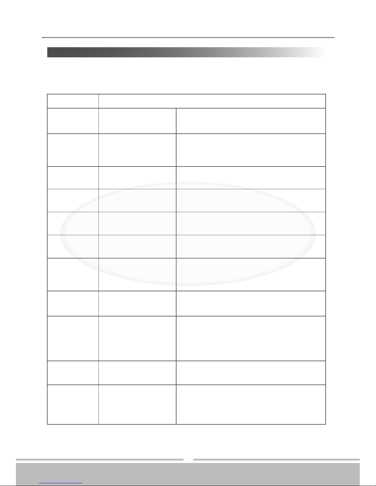
Flash Code Description
1
2
3
4
5
6
7
8
9
10
11
User Fault
Battery Fault
Left Motor Fault
Right Motor Fault
Left Park Brake Fault
Right Park Brake Fault
SHARK Remote Fault
SHARK Power Module
Fault
SHARK
Communications Fault
Unknown Fault
Incompatible Remote
Possible stall timeout or user error.
Release the joystick to neutral and try again.
Try charging the batteries.
Batteries may require replacing.
Check the batteries and cabling.
Check the left motor, connections and
cabling.
Check the right motor, connections and
cabling.
Check the left park brake, connections and
cabling.
Check the right park brake, connections and
cabling.
Check the SHARK Communications Bus
connections and wiring.
Replace the Remote.
Check SHARK connections and wiring.
Replace the Power Module.
Check Battery voltage is greater than 17V.
Check SHARK Bus Cable.
Replace the SHARK Power Module.
Replace the SHARK Remote.
Check all connections and wiring.
Consult a service agent.
The Remote is incompatible with the Power
Module.
Ensure the brand of the Power Module
matches that of the Remote.
Flash codes indicate the nature of an abnormal condition directly from the SHARK lnformation
Gauge. Without the use of any servicing tools, the condition can be simply diagnosed.
18
TROUBLESHOOTING
Instruction Booklet
Page 21

Other Problems:
19
•Power chair will not move when power is turned on :
1.Check Battery Gauge on joystick. All LED lights should be on.
2.Check Self-Diagnostic Warning Light. It should be steady; if it is flashing, see the
chart on page 18 for problem identification.
3.Check all electrical connections to be sure they are tight.
4.Make sure batteries are connected correctly.
5.If none of above correct problem, contact your authorized dealer.
•If charging your scooter for over 14 hours and light on charger does not change to green,
then contact your authorized dealer.
SEREN
Instruction Booklet
Page 22
SEREN
SPECIFICATION
20
Overall Length
Overall Width
Overall Height
Wheels: Front
Wheels: Middle
Wheels: Rear
We
ight w/ Batteries
Max. Speed
Weight Capacity
Ground Clearance
Grade Climbable
Curb Climbing
Tu
rning Radius
Brake
Seat Width
Drive Tr
ain
Battery Weight
Motor Size
Travel Range
Battery
Charger
Electronics
Seat Ty
pe
995 mm / 39"
610 mm / 24"
1080 mm / 42.5"
155 mm / 6"
260 mm / 10"
155 mm / 6"
82 kg / 180.8 lbs
6.7 kmph / 4.2 mph
136 kg / 300 lbs
60 mm / 2.4"
6 degree
40 mm / 1.6"
620 mm / 24.4"
Electro-Mechanical
490 mm / 19"
2-Motor Mid-Wheel Drive
24.2 kg / 53 lbs
420W 4900 r.
p.m
20 km / 12.4 Miles
(2) 12V.
36Ah
5A
Off Board
SHARK
Mid-back Seat w/ Adj.
H
eadrest & Seat Belt
*Subject to change without notice.
Instruction Booklet
Seat Type Mid-back Seat w/ Adj.
Headrest & Seat Belt
Padded, Breathable
Ballistic Nylon Back Rest
Overall Length 995 mm / 39" 995 mm / 39”
Overall Width 610 mm / 24" 610 mm / 24”
Overall Height 1080 mm / 42.5" 930 mm / 37”
Wheels: Front 155 mm / 6" 155mm / 6”
Wheels: Middle 260 mm / 10" 260 mm / 10”
Wheels: Rear 155 mm / 6" 155mm / 6”
Weight w/ Batteries 82 kg / 180.8 lbs 80 kg / 176 lbs
Max. Speed 6.7 kmph / 4.2 mph 6.7 kmph / 4.2 mph
Weight Capacity 136 kg / 300 lbs 136 kg / 300 lbs
Ground Clearance 60 mm / 2.4" 60mm / 2.4”
Grade Climbable 6 degree 6 degree
Curb Climbing 40 mm / 1.6" 40mm / 1.6”
Turnin g Radi us 620 mm / 24.4" 620mm / 24.4”
Brake Electro-Mechanical Electro-Mechanical
Seat Width 490 mm / 19" 420-470 mm / 16.5”-18.5”
Seat Depth 450-475-500 mm / 17.7”-18.7’’-19.6”
Armrest Height 225-250-270 mm / 8.9”-9.8”-10.6”
Seat Back Angle 100 - 120 degree
Seat Back Height 445 mm / 17.5”
Drive Train 2-Motor Mid-Wheel Drive 2-Motor Mid-Wheel Drive
Battery Weight 24.2 kg / 53 lbs 24.2 kg / 53 lbs
Motor Size 420W 4900 r.p.m 420W 4900 r.p.m
Travel Range 20 km / 12.4 Miles 20 km/ 12.4 Miles
Battery (2) 12V. 36Ah (2) 12V. 36Ah
Charger 5A Off Board 5A Off Board
Electronics SHARK SHARK
Page 23

Warranty Information
Drive Medical Seren Powerchairs are warranted for 12months (24 months frame) from the
date of purchase on side frames and crossbars. (NB Baeries are warranted for 12 months.)
»
During the warranty period any parts that have become defective due to
faulty workmanship or material will be repaired or replaced without charge
by Drive Medical supplier/dealer
»
The warranty excludes tyres, punctures and items that become worn due to
normal wear and tear such as upholstery and armrest pads
» The warranty excludes all items that have been subject to undue
wear and tear and misuse
» Unauthorised changes or modications will forfeit your warranty
» If a defect or fault is discovered, the Drive Medical supplier/dealer
from whom the Wheelchair was purchased should be notied immediately
Limitation of Liability
The warranty does not extend to the consequential costs resulting from fault clearance, in
particular freight and travel costs, loss of earnings, expenses, etc. The manufacturer will not
accept responsibility for any damage or injury caused by misuse or non-observance of the
instructions set out in this user manual.
Dealer Stamp
Drive Medical Limited
Ainleys Industrial Estate, Elland
West Yorkshire, HX5 9JP
Tel: +44 (0) 1422 314 488
Fax: +44 (0) 1422 314 489
Email: [email protected]
www.drivemedical.co.uk
 Loading...