


DASHDAQ-XL
DashDAQ XL
Instruction Manual
1

Dear Customer,
Congratulations! You have just purchased the most powerful, sophisticated, and easy to use automotive data logger ever created. The
DashDAQ XL gives everyone access to the powerful information embedded in their vehicle. When it comes to automotive performance,
knowledge is horsepower.
The DashDAQ XL works with any OBD II vehicle. It can also be fitted to any other vehicle using optional add-ons. Now you have a device
that captures information on your new vehicle as well as your vintage one.
This is an exciting time for vehicle performance, and the more you know about your vehicle the more you can get out of it. The
DashDAQ gives automotive enthusiasts the edge in knowing their vehicle, new or old.
Drew Technologies would like to thank you on your decision to buy the DashDAQ XL. However you use your DashDAQ, we know you will
be satisfied with all aspects of the product. You demand the best, we deliver the best.
Thank You,
Drew Technologies, Inc.
2

Table Of Contents
Important Notices ................................................................................................................... 6
Components ............................................................................................................................. 7
Installation............................................................................................................................... 8
SAFETY FIRST! ......................................................................................................................................... 8
OBD II Connector.................................................................................................................................... 8
Cable Routing ......................................................................................................................................... 8
Attaching Windshield Mount ................................................................................................................. 8
Windshield Mounting............................................................................................................................. 9
Connections............................................................................................................................................ 9
SD Memory Card .................................................................................................................................. 10
Basic Operation ..................................................................................................................... 11
Menu Navigation.................................................................................................................................. 11
New Vehicle Setup/Find Signals........................................................................................................... 11
Main Menu and Setup Menu ............................................................................................................... 12
Gauge Setup & Navigation .................................................................................................... 13
Navigating Gauges................................................................................................................................ 13
Assign a Signal to a Gauge.................................................................................................................... 13
Set Gauge Min/Max Values-Optional .................................................................................................. 14
Set Gauge Low Warning / High Warning-Optional .............................................................................. 14
Warning Sounds-Optional .................................................................................................................... 15
Setting Signal/Graph Colors-Optional .................................................................................................. 16
Global Data Logger ............................................................................................................................... 16
Device Manager/Third Party Accessories* ........................................................................... 17
Licensed DashDAQ Drivers ................................................................................................................... 18
Using Device Manager.......................................................................................................................... 18
3

Adding Enhanced OBD II DATA............................................................................................................. 19
Adjusting Driver Parameters ................................................................................................................ 20
Data Logging......................................................................................................................................... 21
Calculators ............................................................................................................................ 22
Installing a Calculator Driver ................................................................................................................ 22
Setting the Parameters for Calculator Drivers ..................................................................................... 23
Dyno Calculator .................................................................................................................................... 23
Fuel Economy Calculator...................................................................................................................... 24
Rescale Signal Calculator...................................................................................................................... 25
Boost Signal Calculator......................................................................................................................... 25
RPM Adjustment Signal Calculator ...................................................................................................... 26
Tire Size Adjustment Calculator ........................................................................................................... 26
Statistics Calculator (Min / Max / Average) ......................................................................................... 26
Performance Measurements ................................................................................................. 27
1/4-mile, 1/8-mile, 0-60mph Test ........................................................................................................ 27
User Defined Speed Tests .................................................................................................................... 28
Diagnostic Code Reader ........................................................................................................ 29
DashDAQ Media Player .......................................................................................................... 30
Customizing your DashDAQ................................................................................................... 31
Installing Files From SD Card ................................................................................................................ 31
Custom Splash Screen .......................................................................................................................... 31
Changing Gauge Themes...................................................................................................................... 31
Adjusting Standard/Metric Units ......................................................................................................... 31
Display Dimmer/Display Brightness ..................................................................................................... 32
Off / On / Low Power Mode................................................................................................................. 32
Default Power-up Screen ....................................................................................................................... 32
4

Analog Inputs......................................................................................................................... 33
Connections and Wiring ....................................................................................................................... 33
Linear Analog Input Driver Setup ......................................................................................................... 33
Linear Analog Driver Correction Factor and Correction Offset............................................................ 34
Converting an Analog Voltage into Physical Units ............................................................................... 34
Non Linear Analog Input Driver Setup ................................................................................................. 35
Non Linear Analog Input Configuration ............................................................................................... 35
Non Linear Analog Input Driver Configuration File .............................................................................. 35
Updating DashDAQ ................................................................................................................ 36
Installing the DashDAQ Recovery Tool................................................................................................. 36
Updating DashDAQ .............................................................................................................................. 38
APPENDIX .............................................................................................................................. 42
Technical Support................................................................................................................................. 42
Technical Specifications ....................................................................................................................... 42
Appendix A: Accessory Cable Pin Out .................................................................................................. 43
Appendix B: CAN expansion Cable Pin Out .......................................................................................... 44
Appendix C: English to Metric Conversion Unit Names ....................................................................... 45
Appendix D: GPS Navigation Setup-Discontinued ............................................................................... 46
Limited Warranty ................................................................................................................................. 47
5

IMPORTANT!
THIS IS A HIGH PERFORMANCE PRODUCT, USE AT YOUR OWN RISK
Do not use this product until you have carefully read the following terms and conditions for the use of this product. The installation of
this product indicates the BUYER has read and understands this agreement and accepts its terms and conditions. This agreement takes
precedence.
DISCLAIMER OF LIABILITY
Drew Technologies and its successors, distributors, jobbers, and dealers (hereafter SELLER) shall in no way be responsible for the
product’s proper use and serviceability.
THE BUYER HEREBY WAIVES ALL LIABILITY CLAIMS.
The BUYER acknowledges that he/she is not relying on the SELLER’s skill or judgment to select or furnish goods suitable for any
particular purpose and that there are no liabilities which extend beyond the description on the face hereof and the BUYER hereby
waives all remedies or liabilities, expressed or implied, arising by law or otherwise, (including without any obligations of the SELLER with
respect to fitness, merchantability, and consequential damages) or whether or not occasioned by the SELLER’s negligence. The SELLER
disclaims any warranty and expressly disclaims any liability for personal injury or damages. The BUYER acknowledges and agrees that
the disclaimer of any liability for person injury is a material term for this agreement and the BUYER agrees to indemnify the SELLER and
to hold the SELLER harmless from any claim related to the item of the equipment purchased. Under no circumstances will the SELLER be
liable for damages or expenses by reason of use or sale of any such equipment. The SELLER assumes no liability regarding the improper
installation or misapplication of its products. It is the installer’s responsibility to check for proper installation and if in doubt, contact the
manufacturer.
IN THE EVENT THAT THE BUYER DOES NOT AGREE WITH THIS AGREEMENT: THE BUYER MAY PROMPTLY RETURN THIS PRODUCT, IN A
NEW AND UNUSED CONDITION, WITH A DATED PROOF OF PURCHASE, TO THE PLACE OF PURCHASE FOR A FULL REFUND. THE
INSTALLATION OF THIS PRODUCT INDICATES THAT THE BUYER HAS READ AND UNDERSTANDS THIS AGREEMENT AND ACCEPTS ITS
TERMS AND CONDITIONS.
Warning: Minnesota and California state laws restrict the method of attachment and placement of objects to the
windshield and side windows of motor vehicles (See Minnesota Statutes 2005, Section 169.71 and California Vehicle
Code Section 26708(a)). Drew Technologies does not take any responsibility for any fines, penalties, or damages that
may be incurred as a result of disregarding the laws and statutes of the jurisdictions in which a DashDAQ is operated.
Similar laws may apply within your province or state. Please verify your provincial or state laws prior to installation.
Warning: When mounting the DashDAQ to the windshield, place the device in a location where it does not obstruct the
driver’s view of the road and does not interfere with vehicle controls and safety devices or the safe operation of the
vehicle.
Attention:
Onstar subscribers may notice an interruption in Onstar diagnostic services while using OBD II scan tool
devices, including DashDAQ. Normal operation will resume once the device has been removed from the OBD II
port.
6
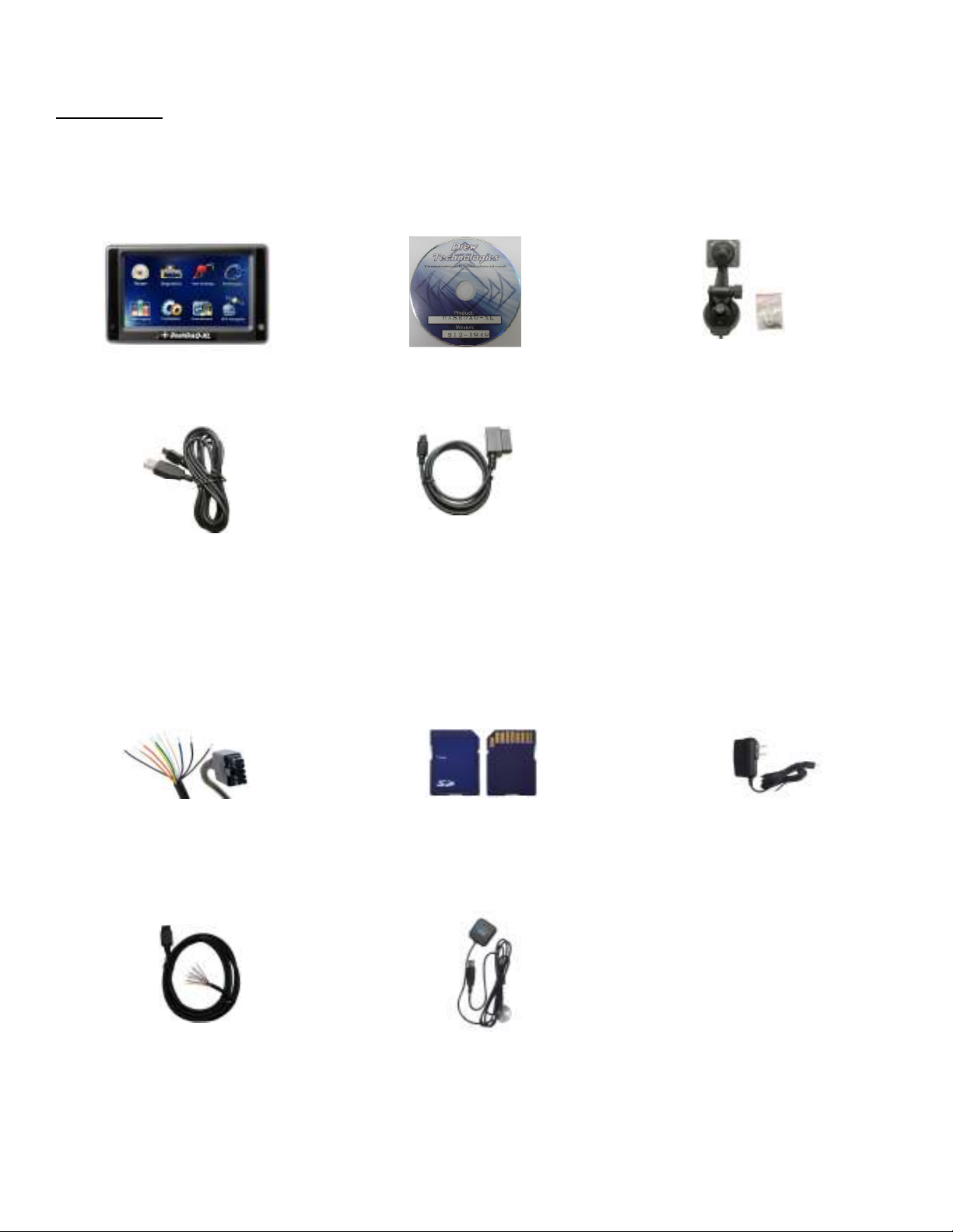
Components
Included with DashDAQ
Display Unit
USB Cable
Optional DashDAQ Accessories
Software CD
OBD II Cable
Windshield Mount with four screws
Accessory Cable
CAN Expansion Cable
SD Memory Card.
GPS Receiver
110V Power Supply
7
INSTALLATI ON
SAFETY FIRST!
Install DashDAQ in such a manner that it does not interfere with the safe operation of the vehicle. If DashDAQ cannot be mounted in
such a manner, promptly return the DashDAQ to Drew Technologies or your purchasing location. Visit www.dashdaq.com to see Drew
Technologies return/refund policy.
OBD II CONNECTOR
The OBD II, or “data link,” connector is necessary for DashDAQ operation in OBD II vehicles. Power and all vehicle information come
directly from this vehicle link.
Most OBD II connectors are found directly below the steering column. If you cannot find the OBD II connector, a local mechanic should
be able to assist you.
*Vehicles not equipped with OBD II may require additional hardware. See Device Manager/Third Party Accessories (pg 17) for more
info.
CABLE ROUTING
The DashDAQ OBD II cable must be routed so that it does not interfere with safe operation of the vehicle.
Cable routing tips:
• Find the OBD II connector first and work the cable to where DashDAQ is to be mounted on the windshield.
• Route the DashDAQ OBD II cable between interior panel grooves to hold the cable as well as conceal it.
• Use wire or zip ties to bundle any excess cable.
Cable routing “Don’ts”
• Don’t let the cable dangle by your feet.
• Don’t let the cable hang free.
• Keep the cable away from the steering wheel and any steering column controls.
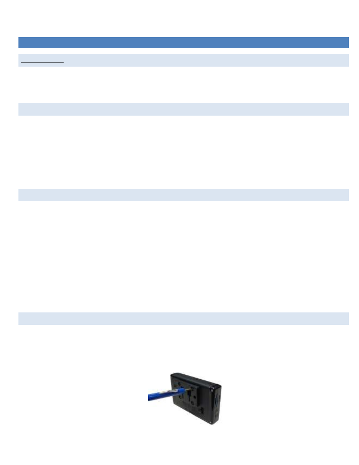
ATTACHING WINDS H I E L D MOUNT
1. Remove these two items from packaging:
a. Display Unit
b. Windshield Mount
2. Line up the four holes on the windshield mount and thread each of the four screws into the display unit.
3. Using a Phillips head screwdriver, lightly tighten each of the four screws. Note: Over tightening can cause the mount to crack.
Attaching the windshield mount to DashDAQ
8

WINDSHIELD MOU NT I NG
Mount the DashDAQ on the windshield in a spot that does not obstruct the view of the road or in any way that interferes with the safe
operation of the vehicle.
Mounting Suggestions:
• Mount the DashDAQ as low to the dashboard as possible.
• Mounting to the left or in the middle works well.
CONNECTIONS
Audio Output
Accessory Port
OBD II Port
USB Update
Port
USB Ports
Power Button
MMC SD Memory
Card Slot
Light Sensor
9
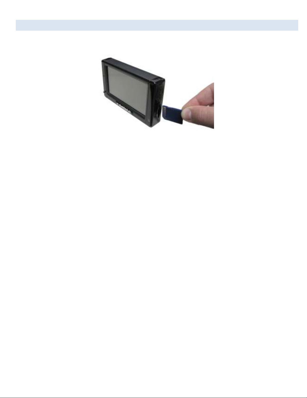
SD MEMORY C A R D
Always insert and remove the memory card with the DashDAQ powered off. Insert the card with the gold connections facing towards
the screen. Press the card into the DashDAQ until a click is heard. If the card sticks out at all, it has not been pushed in all the way.
To remove, press the card in until a click is heard. Release and the card will eject enough to grab it.
10
BASIC OPERA T I ON
MENU NAVIGATION
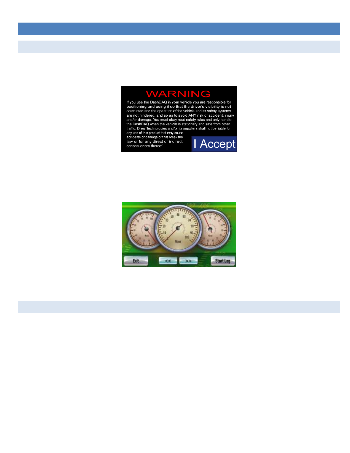
When DashDAQ first starts up, a boot screen will appear. Start will take a few moments to start up.
When this warning screen appears, please read carefully.
To continue, tap the [I Accept] button. If you do not agree to abide by the warning, please disconnect DashDAQ and contact Drew
Technologies for a return authorization.
Tapping the [I Accept] button will bring up the gauge screen:
The [<<] and [>>] arrow buttons at the bottom are used to cycle through different gauge layouts.
The [Exit] button in the lower left corner returns the screen to the main menu for accessing all of DashDAQ’s features.
NEW VEHICLE SE T U P /FIND SIGNALS
The DashDAQ has been designed to be used on any 1996 and newer OBD II vehicle. Vehicles, which the DashDAQ is connected, will
typically offer a different set of parameters or signals available.
The New Vehicle setup:
1. Plug DashDAQ into the vehicle.
2. Turn the vehicle’s key to the on position. The engine does not need to be started.
3. Turn on the DashDAQ.
4. From the DashDAQ main menu, Tap [Setup], tap [Devices].
5. Tap [Find Signals].
6. Follow the on-screen instructions. When DashDAQ lists how many signals were found, DashDAQ has finished.
7. Repeat steps 1-6 every time DashDAQ is connected to a new vehicle.
*Signals may appear and not function if the New Vehicle Setup is not run when the DashDAQ is connected to a different vehicle
11
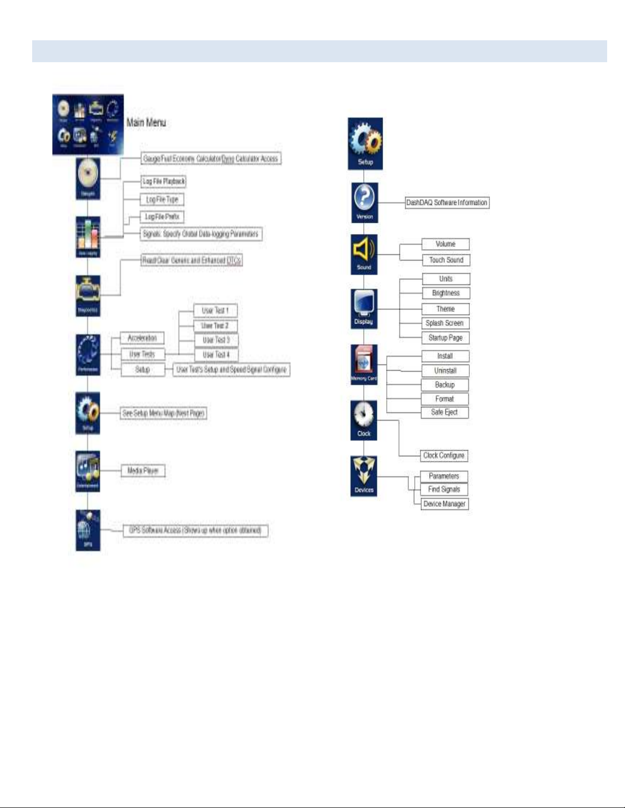
MAIN MENU AND S E T UP MENU
12

GAUGE SETUP & NA VI G A TI ON
DashDAQ offers the ability to monitor hundreds of vehicle sensors for real time display and data logging. Data sample rates will vary by
vehicle. This rate is a fixed amount and the total of active signal being monitored and logged will share this sample rate.
NAVIGATING GAUGE S
From the Main Menu tap [Gauges].
Layout with 3 round gauges
Tap on the [<<] and [>>] buttons to view other gauge layout options. Two gauge layout examples:
Layout for graphing up to 8 signals
Layout for displaying up to 9 numeric signals
ASSIGN A SIGNAL T O A GA U G E
Be sure the New Vehicle Setup (pg 11) has been completed before assigning signals to a gauge.
1. Tap on the gauge region where the signal will be displayed. This screen will appear:
Assign signal screen
2. Tap on [Signal] area in the black region.
3. Use the [<] or [>] at the top to select the Data group you wish to select your signals from.
4. Use the scroll bar to the right to locate and select the signal you wish to monitor.
5. Tap [Save].
13

SET GAUGE MIN/M A X VALUES-OPTIONAL
Tap on the [Low Limit] button to set the bottom value for the signal.
Tap on the [High Limit] button to set the top value for the signal.
1. Tap [Low Limit] or [High Limit] will bring up this screen:
Entering maximum value for a gauge
2. Type in the desired value.
3. To make the value negative tap [+/-].
4. Tap [save]
5. Repeat steps 1-4 to set the signal’s minimum value.
SET GAUGE LOW W A R NI N G / H I G H W AR N IN G - OPTIONAL
You can also create an upper and lower “redline” region on the DashDAQ. The below gauge has a “redline danger zone” between 5000
and 6000 RPM.
To set a High/Low Warning:
1. Tap on the gauge where a High/Low Warning is to be set.
2. On the Assign Signal screen, tap on [High Warning] or [Low Warning].
3. Type in the desired upper or lower warning level number. Tap [+/-] to make the value negative.
4. Tap [Save].
5. Tap [Save] on the Assign Signal screen to go back to the gauges.
Round gauge with a high limit warning
14
WARNING SOUNDS - O PT IO N A L
DashDAQ can also play a pre-installed or user defined audible warning when a signal has entered the upper or lower warning area.
To set a Warning Sound:
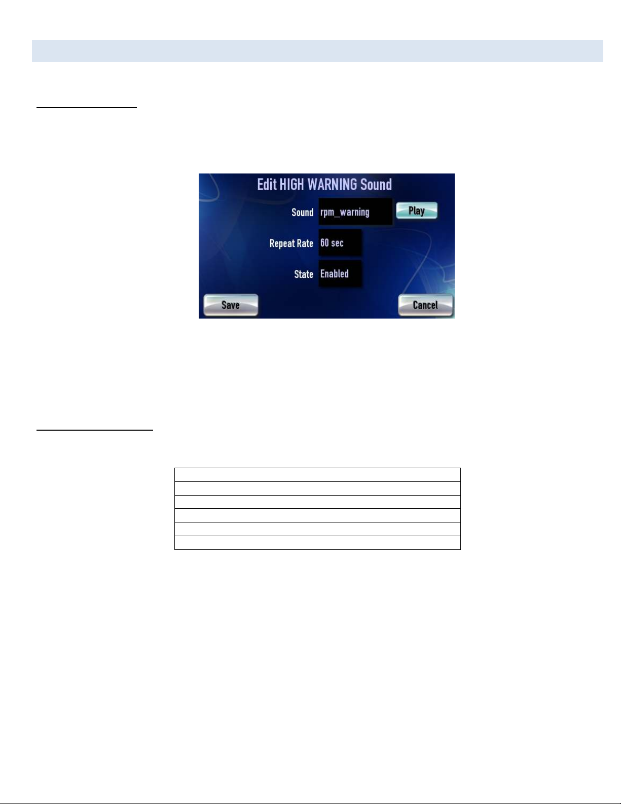
1. Tap on a gauge that you want the warning sound to be apparent on.
2. Tap on the crossed out speaker for either the High or Low warning.
3. Tap on the black box next to “Sound” to select the audio clip to be played when the threshold is crossed.
High Warning sound set for RPM warning.
4. The repeat rate is how often the sound will repeat while the threshold is crossed. 0 will repeat constantly.
5. The “State” field will either enable or disable the warning. Tap [Save].
6. Make sure your warning threshold for the high or low warning that you use is set, and make sure your signal for the gauge is
specified.
To upload your own sounds:
1. Sound files must have these attributes:
Extension: .wav
Encoding: PCM (uncompressed)
Size: 8 or 16 bit signed integer
Sample Rate: 22050, 11025, 5512 or 5513 KHZ
Channels: Stereo or Mono
Length: Less than 10 seconds
2. Create a folder on your SD called named “Transfer,” and place file inside folder.
3. Insert the SD into the DashDAQ, and turn the unit on.
4. From the Main Menu tap on [Setup], then [Memory Card], then [Install], then [Sound].
5. Select which sound you wish to install and tap [Install].
You can now specify this warning sound for any High or Low warning in the gauges.
15
 Loading...