

Page 1
Owner’s Manual
ADVANTAGE
™
High Speed Rotary Saw
Model 9000
™
• Safety
• Descriptions
• Assembly
• Operation
• Maintenance and Service
• Warranty
P.O. Box 1468
Racine, Wisconsin 53401
Parlez-vous français?
Voir page 13
¿Habla español?
Vea página 25
1-800-437-3635
www.dremel.com
2610913622 3/02 PRINTED IN U.S.A.
Page 2

Power Tool Safety Rules
WARNING
!
Read and understand all instructions. Failure to follow all instructions
listed below, may result in electric shock, fire and/or serious personal injury.
SAVE THESE INSTRUCTIONS
Work Area
Keep your work area clean and well lit.
C l u t t e red benches and dark areas invite
a c c i d e n t s .
Do not operate power tools in ex p l o s i v e
atmospheres, such as in the presence of
f l a m m a ble liquids, gases, or dust. P o w e r
tools create sparks which may ignite the dust
or fumes.
Keep by - s t a n d e rs, children, and visitors
aw ay while operating a power tool.
Distractions can cause you to lose contro l .
Electrical Safe t y
Double Insulated tools are equipped with
a polarized plug (one blade is wider than
the other.) This plug will fit in a polarized
outlet only one way. If the plug does not
fit fully in the outlet, reverse the plug. If it
still does not fit, contact a qualified
electrician to install a polarized outlet. Do
not ch a n ge the plug in any way. D o u b l e
Insulation eliminates the need for the
t h r ee wire ground ed power cord an d
g rounded power su pply sys tem. B e fo r e
plugging in the tool, be certain the outlet
voltage supplied is within the voltage marked
on the nameplate. Do not use “AC only” rated
tools with a DC power supply.
Avoid body contact with grounded surfaces
s u ch as pipes, radiators, ranges and
r e f r i ge r a t o rs . T h e re is an increased risk of
electric shock if your body is grounded. If
operating the power tool in damp locations is
unavoidable, a Ground Fault Circuit Interrupter
must be used to supply the power to your
tool. Electrician’s rubber gloves and footwear
will further enhance your personal safety.
Don't expose power tools to rain or wet
c o n d i t i o n s . Water entering a power tool will
i n c rease the risk of electric shock.
Do not abuse the cord. Never use the cord
to carry the tools or pull the plug from an
outlet. Keep cord aw ay from heat, oil, sharp
e d ges or moving parts. Replace damage d
c o rds immediately. Damaged cords incre a s e
the risk of electric shock.
When operating a power tool outside, use
an outdoor extension cord marked "W- A "
or "W." These cords are rated for outdoor use
and reduce the risk of electric shock. Refer to
“Recommended sizes of Extension Cords” in
the Accessory section of this manual.
Pe rsonal Safe t y
S t ay alert, watch what you are doing and
use common sense when operating a
p ower tool. Do not use tool while tired or
under the influence of drugs, alcohol, or
m e d i c a t i o n . A moment of inattention while
operating power tools may result in serious
personal injury.
Dress pro p e r ly. Do not wear loose cl o t h i n g
or jew e l ry. Contain long hair. Keep yo u r
h a i r, clothing, and gloves aw ay fro m
m oving parts. Loose clothes, jewelry, or long
hair can be caught in moving parts. Keep
handles dry, cl ean and free from oil and
g re a s e .
Avoid accidental starting. Be sure sw i t ch is
“OFF” before plugging in. Carrying tools
with your finger on the switch or plugging in
tools that have the switch “ ON ” invite s
a c c i d e n t s .
R e m ove adjusting keys or wrenches befo r e
turning the tool “ON”. A wrench or a key that
is left attached to a rotating part of the tool
may result in personal injury.
Do not ov e r r e a ch. Keep proper footing and
balance at all times. P roper footing and
balance enables better control of the tool in
unexpected situations.
Use safety equipment. Alw ays wear eye
p ro t e c t i o n . Dust mask, non-skid safety shoes,
h a rd hat, or hearing protection must be used
for appropriate conditions.
Tool Use and Care
Use clamps or other practical way to
secure and support the workpiece to a
s t a ble platfo r m . Holding the work by hand or
against your body is unstable and may lead to
loss of contro l .
Do not fo rce tool. Use the correct tool fo r
your application. The correct tool will do the
job better and safer at the rate for which it is
d e s i g n e d .
Page 2
Do not use tool if sw i t ch does not turn it
“ON” or “OFF”. Any tool that cannot be
c o n t rolled with the switch is dangerous and
must be re p a i re d .
Disconnect the plug from the power sourc e
b e fore making any adjustments, ch a n g i n g
accessories, or storing the tool. S u c h
p reventive safety measures reduce the risk of
starting the tool accidentally.
Store idle tools out of reach of children and
other untrained pers o n s . Tools are
d a n g e rous in the hands of untrained users.
Maintain tools with care. Keep cutting tools
sharp and cl e a n . P roperly maintained tools,
with sharp cutting edges are less likely to bind
and are easier to control. Any alteration or
modification is a misuse and may result in a
d a n g e rous condition.
C h e ck for misalignment or binding of
m oving parts, breakage of parts, and any
other condition that may affect the tools
operation. If damaged, have the tool
s e rviced before using. Many accidents are
Rotary Saw Safety Rules
Hold tool by insulated gripping surfaces
when performing an operation where the
cutting tool may contact hidden wiring or
its own cord. Contact with a "live" wire will
make exposed metal parts of the tool "live"
an d shock the op erato r. If cutting into
existing walls or other blind areas where
e l e c t rical wiring may exist is unavo i d a bl e,
disconnect all fuses or circuit breake r s
feeding this worksite.
A lw ays make sure the work surface is
free from nails and other foreign objects.
Cutting into a nail can cause the bit and the
tool to jump and damage the bit.
Never hold the workpiece in one hand and
the tool in the other hand when in use.
N ever place hands near or below cutting
surface. Clamping the material and guiding
the tool with both hands is safer.
N ever lay workpiece on top of hard
surfaces, like concrete, stone, etc...
P rotruding cutting bit may cause tool to
jump.
caused by poorly maintained tools. Develop a
periodic maintenance schedule for your tool.
Use only accessories that are recommended by the manufacturer for yo u r
model. Accessories that may be suitable for
one tool, may become hazardous when used
on another tool.
S e rv i c e
Tool service must be performed only by
qualified repair pers o n n e l . Servic e or
main te nance performed by unqualified
personnel could result in a risk of injury. For
example: internal wires may be misplaced or
pinched, safety guard re t u rn springs may be
i m p roperly mounted.
When servicing a tool, use only identical
replacement parts. Follow instructions in
the Maintenance section of this manu a l .
Use of unauthorized parts or failure to follow
Maintenance Instructions may create a risk of
electric shock or injury. Certain cleaning
agents such as gasoline, carbon tetrachloride,
ammonia, etc. may damage plastic parts.
A lw ays wear safety goggles and dust
mask. Use only in well ventilated area.
Using personal safety devices and working
in safe environment reduces risk of injury.
After changing the bits or making any
adjustments, make sure the collet nut and
a ny other adjustment devices are
s e c u r e ly tightened. Lo ose adjustment
device can unexpectedly shift, causing loss
of control, loose rotating components will be
violently thrown.
N ever start the tool when the bit is
e n g aged in the material. The bit cutting
edge may grab the material causing loss of
control of the cutter.
A lw ays hold the tool with two hands
during start-up. The reaction torque of the
motor can cause the tool to twist.
The direction of feeding the bit into the
material is very important and it relates to
the direction of bit rotation. Most materials
should be cut in a clockwise direction. An
exception is when cutting around an outlet
Page 3
Page 3
box in drywall, which should be cut counterclockwise. Steering the tool in the wro n g
direction, causes the cutting edge of the bit
to climb out of the work and pull the tool in
the direction of the feed.
N ever use dull or damaged bits. Sharp
bits must be handled with care. Damaged
bits can snap during use. Dull bits re q u i re
m o re force to push th e tool, possibly
causing the bit to break.
Never touch the bit during or immediately
after the use. After use the bit is too hot to
be touched by bare hands.
N ever lay the tool down until the motor
has come to a complete standstill. T h e
spinning bit can grab the surface and pull
the tool out of your control.
N ever use bits that have a cutting
diameter greater than the opening in the
base.
Do not use the tool for drilling purposes.
This tool is not intended to be used with drill
bits.
S y m b o l s
!
WARNING
Some dust created by
p ower sanding, saw i n g ,
grinding, drilling, and other construction
activities contains chemicals known to
cause cancer, birth defects or other
r e p roductive harm. Some examples of
these chemicals are:
• Lead from lead-based paints,
• Crystalline silica from bricks and cement
and other masonry products, and
• Arsenic and chromium from chemically-
treated lumber.
Your risk fro m t he se exposu re s var ie s,
depending on how often you do this type of
work. To reduce your exposure to these
chemicals: work in a well ventilated are a ,
and work with approved safety equipment,
such as those dust masks that are specially
designed to filter out microscopic particles.
Always use the tool with the depth guide
s e c u r e ly attached and positioned flat
against material being cut. The guide
securely positioned on the material improves
the stability and control of your tool.
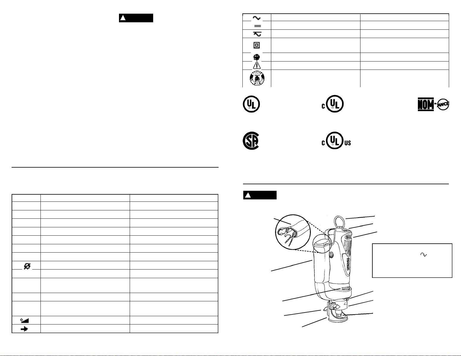
A l t e rnating curre n t Type or a characteristic of curre n t
D i rect curre n t Type or a characteristic of curre n t
A l t e rnating or direct curre n t Type or a characteristic of curre n t
Class II construction Designates Double Insulated
Construction tools.
Earthing terminal G rounding terminal
Wa rning symbol Alerts user to warning messages
Ni-Cad RBRC seal Designates Ni-Cad battery re c y c l i n g
p ro g r a m
This symbol designates
that this tool is listed by
Underwriters Laboratories.
This symbol designates
that this tool is listed to
Canadian Standards by
Underwriters Laboratories.
This symbol designates
This symbol designates
that this tool is listed by
the Canadian Standard s
A s s o c i a t i o n .
that this tool is listed by
Underwriters Laboratories,
and listed to Canadian
S t a n d a rds by Underwriters
L a b o r a t o r i e s .
This symbol
d e s i g n a t e s
t h a t
this tool
c o m p l i e s
to NOM
M e x i c a n
S t a n d a rd s .
IMPORTANT: Some of the following symbols may be used on your tool. Please study them
and learn their meaning. Proper interpretation of these symbols will allow you to operate the
tool better and safer.
S y m b o l N a m e D e s i g n a t i o n / E x p l a n a t i o n
V Vo l t s Voltage (potential)
A A m p e re s C u r re n t
H z H e r t z F requency (cycles per second)
W Wa t t P o w e r
k g K i l o g r a m s We i g h t
m i n M i n u t e s T i m e
s S e c o n d s T i m e
D i a m e t e r Size of drill bits, grinding wheels, etc.
n
0
No load speed Rotational speed, at no load
. . . / m i n Revolutions or re c i p rocation per minute Revolutions, strokes, surface speed,
orbits etc. per minute
0 O ff position Z e ro speed, zero torq u e . . .
1, 2, 3, ... Selector settings Speed, torque or position settings.
I, II, III, Higher number means greater speed
Infinitely variable selector with off Speed is increasing from 0 setting
A r ro w Action in the direction of arro w
Page 4
Functional Description and Specifications
WARNING
!
measures reduce the risk of starting the tool accidentally.
TO O L
S TO R AG E
AU X I L I A RY
H A N D L E
E X H AUST
AIR VENTS
DEPTH GUIDE
LOCKING WINGNUT
Disconnect the plug from the power source before making any
assembly, adjustments or changing accessories. Such preventive safety
DEPTH GUIDE
Page 5
HANG BA I L
I N TAKE AIR VENTS
SPEED DIAL
Model number 9000
Voltage rating 120V 50 - 60Hz
Amperage rating 4.5 A
No load speed n0 1 0 , 0 0 0 - 3 5 , 0 0 0 /m i n
Collet capacities 1 / 8", 1 / 4"
SHAFT LOCK
DEPTH GUIDE BRAC K E T
COLLET NUT
Page 4

Page 5

WARNING
!
Do not attempt to use this
tool to make cut-outs
a round any fixture or opening which has
live electrical wires, or on any wall which
m ay have live electrical wiring behind it,
as the bit could conduct current to the
tool, creating an electrocution hazard fo r
the operator. Shut off breakers or re m o v e
fuses to disconnect the circuit. Always hold
the tool by its thermoplastic housing, and
always wear eye protection when operating
this device.
• Step 1: Be certain that the box or fixture
which re q u i res a cut-out is firmly mounted
and all wires or other obstructions aro u n d
the opening are pushed back out of the way.
The drywall cut-out bit uses the outer edge
of the box or fixture as a guide, so it is
important that there is nothing in the way
which can prevent it from guiding completely
around the opening. For the purposes of this
instruction manual, the procedure discussed
will be to make a cut-out around a standard
2 1/8" x 3 3/4" electrical box.
• Step 2: Before fastening the drywall sheet,
make a mark close to the center of the
opening in the box on the side of the drywall
facing you. You may then begin to screw or
nail the sheet to the wall, but do not install
fasteners closer then about 15" to the box,
or the sheet will likely bulge and crack before
you cut the opening.
• Step 3: Holding the tool firmly switch the
tool to th e "ON " pos ition as described
earlier.
• Step 4: Holding the tool firmly with both
hands, push the bit through the drywall at
the mark you made in step 2. Guide the bit
to the right until you feel it make contact with
the inside edge of the box. Then retract the
bit slightly, (do not pull entirely out) to allow it
to penetrate through the drywall and contact
the outside edge of the box by continuing to
move the tool slightly to the right as you cut.
• Step 5: Keeping the bit in contact with the
outside of the box, move the tool counterclockwise to crea te the opening. When
ro unding a co rn e r, keep app lying li gh t
pressure towards the center of the box while
moving the bit steadily and smoothly around
the whole box until the entire cut has been
completed. Slide the switch to the "OFF"
position, and pull the bit free of the drywall.
You may then remove the piece you have
cut, and you will have a smooth opening.
The rest of the screws or nails may now be
put in place on the drywall sheet, and the
task is completed.
CAUTION
!
The motor may stall if
i m p ro pe rly used or overloaded. Reduce the pre s s u re or feed rate to
p revent possible damage to the tool. Do not
attempt to start the tool when the bit is
engaged in the workpiece. Always be sure the
collet nut is tightened securely before use.
Page 8
MAKING CUT-OUTS IN MATERIALS
OTHER THAN DRYWALL
Your tool is capable of cutting many types of
building materials in addition to drywall.
T h e re are several diff e rent bits available for
use on these materials. Most materials can
be cut with the "multipurpose" bit, however
the "carbide" burr bits must be used for
h a rd, abrasive materials such as ceramic
wall tile (will not work on ceramic floor grade
tile), cement board, plaster etc.
To ma ke cut-outs, insert and adjust the
proper bit according to previous instructions.
Hold the tool firmly and turn it on. Place the
depth guide at about a 45º angle against the
work surface and tilt the tool to an upright
po sition with the bit entering the scrap
portion of the area being cut. Move the bit to
the line you wish to follow and cut in a
clockwise direction. Cutting at a slow even
rate will make following a line easier and will
put less stress on the bit.
N OT E : When cutting on a vertical surface,
avoid ending your cut at the bottom of the
hole. If possible, start and end your cut at
the top so the scrap part will not drop onto
the rotating bit. Turn the tool off and remove
it from the cut out hole.
Maintenance Information
C L E A N I N G
To avoid accidents alw ays disconnect the
tool from the power supply before cl e a n i n g
or performing any maintenance. The tool
may be cleaned most effectively with
c o m p ressed dry air. A lw ays wear safety gog-
gles when cleaning tools with compressed
a i r. Ventilation openings and switch levers
must be kept clean and free of foreign matter.
Do not attempt to clean by inserting pointed
objects through openings.
!
CAUTION
p a rt s . Some of these are: gasoline, carbon
tetrachloride, chlorinated cleaning solvents,
ammonia and household detergents that
contain ammonia.
C e rtain cleaning agents and
solvents damage plastic
P r eventive maintenance performed by
SERVICE
u n a u t h o r i zed personnel may result in
misplacing of internal wires and
components which could cause serious
h a z a rd. We recommend that all tool service be
performed by a Dremel Service Facility.
FIG. 11
BRUSH & SPRING
ASSEMBLY
B RUSH CA P
CURVED END OF BRU S H
MUST MATCH CURVAT U R E
OF HOUSING
CARBON BRU S H E S
The brushes and commutator in your tool have
been engineered for many hours of dependable
service. To maintain peak efficiency of the
m o t o r, we recommend every two to six months
the brushes be examined. Only genuine Dre m e l
replacement brushes specially designed for
your tool should be used.
MAINTENANCE OF REPLAC E A B L E
B RUSHES Model 9000
The brushes should be inspected fre q u e n t l y
when tools are used continuously. If your tool
runs sporadically, loses power, makes unusual
noises or runs at a reduced speed, check the
brushes. To continue using the tool in this
condition will permanently damage your tool.
With the cord unplugged, remove the brush
caps one at a time with a small screwdriver by
rotating cap counter-clockwise and check each
b r u s h .
If the brush is less than 1/4" long and the end
surface of the brush that contacts the
commutator is rough and/or pitted, they should
be replaced. Check both brushes. Usually the
brushes will not wear out simultaneously. If one
brush is worn out, replace both brushes. Make
s u re the brushes are installed as illustrated. The
curved surface of the brush must match the
c u r v a t u re of the commutator.
After replacing brushes the tool should be run
at no-load; place it on a clean surface and run it
f reely for 5 minutes before loading (or using) the
tool. This will allow the brushes to “seat”
p roperly and will give you more hours of life
f rom each set of brushes. This will also extend
the total life of your tool since the commutator
surface will “wear” longer.
B e a r i n g s - Model 9000 is equipped with ball
bearing construction. Under normal use no
additional lubrication is re q u i re d .
Page 9
C U R VATURE
OF HOUSING
Page 6

If an extension cord is necessary, a cord
Extension Cord s
with adequate size conductors that is
capable of carrying the current necessary
for your tool must be used. This will prevent
excess ive voltage drop, loss of power or
overheating. Grounded tools must use 3-wire
extension cords that have 3-prong plugs and
receptacles.
N OT E : The smaller the gauge number, the
heavier the cord .
RECOMMENDED SIZES OF EXTENSION
CORDS 120 VOLT ALTERNATING
CURRENT TOOLS
Tool’s
Ampere
Rating
3 - 6
6 - 8
8 - 1 0
1 0 - 1 2
1 2 - 1 6
Cord Size in A.W.G.
Cord Length in Feet Cord Length in Meters
2 5 5 0 1 0 0 1 5 0 1 5 3 0 6 0 1 2 0
1 8 1 6 1 6 1 4 . 7 5 . 7 5 1 . 5 2 . 5
1 8 1 6 1 4 1 2 . 7 5 1 . 0 2 . 5 4 . 0
1 8 1 6 1 4 1 2 . 7 5 1 . 0 2 . 5 4 . 0
1 6 1 6 1 4 1 2 1 . 0 2 . 5 4 . 0 —
1 4 1 2 — — — — — —
Wire Sizes in mm
D r emel Advantage Service
Parts Diagram
Dremel Advantage™
Service Parts List
2
Ref. No. Part Part No.
1 Depth Guide Cutting Base Plate 2610916273
2 Depth Guide Wingnut (pair) 2610914431
3 Depth Guide Nut Plate 2610913184
4 Depth Guide Retainer 2610916274
5 Retainer nut 3603301505
6 Collet nut 2610913319
7 1/8" Collet 2615295093
8 Wrench 2615295097
9 Shaft lock assembly 2610907116
10 Shaft lock retaining ring 2610909201
11 Brush caps (pair) 2610913159
12 Motor brushes and springs (pair) 2610913160
13 Motor brush holder with straight lead 2610915244
14 Motor brush holder with right angle lead 2610915245
15 Cap for on/off switch 2610913156
16 On/off switch 2610996245
17 Power cord 2610913157
18 Speed control assembly 2610913155
19 Motor assembly 2610914664
20 Field assembly 2604220677
21 Rubber isolator ring 2615297373
22 Screws (five) 2610326578
23 Handle assembly 2610913023
24 Housing set with labels 2610907339
25 Tool hanger 2610913164
O rder by part number, not re f e rence number.
Write for current price or call 1-800-4 DREMEL
Page 11Page 10
Page 7

Dremel Limited Wa r r a n t y
Your Dremel product is warranted against defective material or workmanship for a
period of two years from date of purchase. In the event of a failure of a product to
conform to this written warranty, please take the following action:
1. DO NOT return your product to the place of purchase.
2. Carefully package the product by itself, with no other items, and return it, freight
prepaid, along with:
A. A copy of your dated proof of purchase (please keep a copy for yourself).
B. A written statement about the nature of the problem.
C. Your name, address and phone number to:
UNITED STATES
Dremel Service Center D remel Service Center
4915 Tw e n t y - F i rst Street OR 4631 E. Sunny Dunes
R a c i n e, Wisconsin 53406 Palm Springs, CA 92264
C A N A DA OUTSIDE
Giles Tool Agency CONTINENTAL UNITED STATES
6520 Lawrence Av. East See your local distributor or write
S c a r b o rough, Ont. to Dremel, 4915 Twenty-First St.
Canada M1C 4A7 Racine, Wisconsin 53406
We recommend that the package be insured against loss or in transit damage for
which we cannot be responsible.
This warranty applies only to the original re g i s t e red purc h a s e r. DAMAGE TO THE
PRODUCT RESULTING FROM TAMPERING, ACCIDENT, ABUSE, NEGLIGENCE,
UNAUTHORIZED REPAIRS OR ALT E R ATIONS, UNAPPROVED AT TACHMENTS OR
OTHER CAU SES U NR ELATED T O P ROBLEMS WITH M ATERI AL OR
WORKMANSHIP ARE NOT COVERED BY THIS WARRANTY.
No employee, agent, dealer or other person is authorized to give any warranties on
behalf of Dremel. If Dremel inspection shows that the problem was caused by
problems with material or workmanship within the limitations of the warranty, Dremel
will repair or replace the product free of charge and return product prepaid. Repairs
made necessary by normal wear or abuse, or repair for product outside the warranty
period, if they can be made, will be charged at regular factory prices.
DREMEL MAKES NO OTHER WARRANTY OF ANY KIND WHATEVER, EXPRESSED
OR IMPLIED, AND ALL IMPLIED WARRANTIES OF MERCHANTABILITY AND FITNESS
FOR A PA RTIC ULAR PUR POSE WHICH E XCEED THE ABOVE MENTIONED
O B L I G ATION ARE HEREBY DISCLAIMED BY DREMEL AND EXCLUDED FROM THIS
LIMITED WA R R A N T Y.
This warranty gives you specific legal rights and you may also have other rights which
vary from state to state. The obligation of the warrantor is solely to repair or replace the
p roduct. The warrantor is not liable for any incidental or consequential damages due to
any such alleged defect. Some states do not allow the exclusion or limitation of
incidental or consequential damages, so the above limitations or exclusion may not
apply to you.
For prices and warranty fulfillment in the continental United States, contact your local
D remel distributor.
Page 12
 Loading...