

Page 1
ÉQUIPEMENT DOYON INC.
1255, rue Principale
Linière, Qc, Canada G0M 1J0
Tel.: 1 (418) 685-3431
Canada: 1 (800) 463-1636
US: 1 (800) 463-4273
FAX: 1 (418) 685-3948
Internet: http://www.doyon.qc.ca
e-mail: doyon@doyon.qc.ca
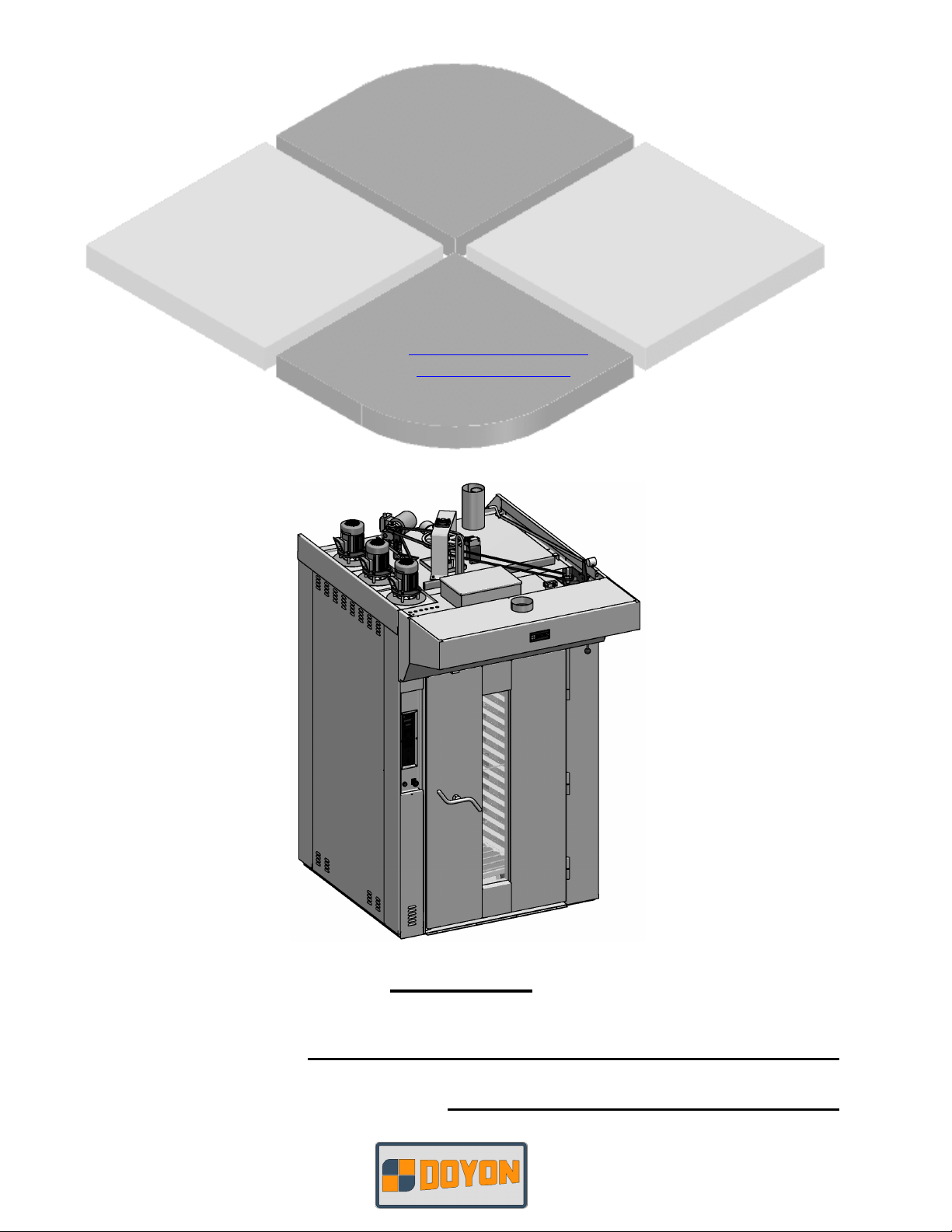
TLOI - TLOII
Product / Produit:
Serial number / Numéro de série:
Page 2

IMPORTANT SAFETY INSTRUCTIONS
SAVE THESE INSTRUCTIONS
DANGER
TO REDUCE THE RISK OF FIRE OR ELECTRIC SHOCK
CAREFULLY FOLLOW THESE INSTRUCTIONS
TABLE OF CONTENTS
(table des matières :page suivante)
DESCRIPTION________________________________________________________________ A-1
Introduction________________________________________________________________ A-1
Construction _______________________________________________________________ A-1
Shipping __________________________________________________________________ A-1
Installation warnings_________________________________________________________ A-3
Distances to respect for the installation near flammable products ______________________ A-3
Installation ________________________________________________________________ A-5
ECM-1 Programmable control - Operating modes__________________________________ A-7
Manual mode ______________________________________________________________ A-9
Program mode_____________________________________________________________ A-10
Troubleshooting ___________________________________________________________ A-21
Oven maintenance and cleaning _______________________________________________ A-23
Maintenance and lubrication__________________________________________________ A-23
Lubication ________________________________________________________________ A-25
COMPONENT PARTS __________________________________________________________B-1
TLOI – Front view ___________________________________________________________B-1
TLOII – Top view____________________________________________________________B-3
Rack hloder assembly _________________________________________________________B-5
CONTROL PANELS ____________________________________________________________C-1
TLO break rack panel _________________________________________________________C-1
TLO1 3PH 120/208 120/240V 60Hz _____________________________________________C-2
FAM TLOE.doc 04/09
Page 3

IMPORTANT INSTRUCTIONS DE SÉCURITÉ
CONSERVEZ CE MANUEL D’INSTRUCTIONS
DANGER
AFIN DE RÉDUIRE LES RISQUES D'INCENDIE OU D'ÉLECTROCUTION
SUIVRE CES INSTRUCTIONS AVEC SOIN
TABLE DES MATIÈRES
DESCRIPTION _________________________________________________________________A-2
Introduction ________________________________________________________________A-2
Construction ________________________________________________________________A-2
Expédition __________________________________________________________________A-2
Avertissement lors de l'installation_______________________________________________A-4
Distances à respecter lors de l’installation près de produits inflammables________________A-4
Installation _________________________________________________________________A-6
Contrôle programmable ECM-1 - Modes d'opération _______________________________A-14
Mode manuel_______________________________________________________________A-16
Mode programmable_________________________________________________________A-17
Dépannage ________________________________________________________________A-22
Entretien et nettoyage du four__________________________________________________A-24
Entretien et lubrification______________________________________________________A-24
Lubrification _______________________________________________________________A-25
PIÈCES COMPOSANTE _________________________________________________________B-1
TLOI – Vue de face ___________________________________________________________B-1
TLOII – Vue de dessus ________________________________________________________B-3
Support de chariot ___________________________________________________________B-5
PANNEAUX DE CONTRÔLE _____________________________________________________C-1
TLO panneau arrêt chariot_____________________________________________________C-1
TLO1 3PH 120/208 120/240V 60Hz______________________________________________C-2
Page 4

A-1
SECTION A:
DESCRIPTION
INTRODUCTION
The manufacturer suggests to read this manual carefully.
This equipment is manufactured with first quality material by experienced technicians. Proper
installation and maintenance will guarantee a reliable service for years to come.
A nameplate fixed to the front or right side of the oven specifies the model number, serial number,
voltage and amperage.
Drawings and replacement parts numbers are included in this manual. The electrical diagram is affixed
in the control panel at the back of the oven.
ATTENTION
DOYON is not responsible for damages to the property or the equipment caused
by personnel who is not certified by known organisations. The customer is
responsible for finding qualified technicians in electricity and plumbing for the
installation of the oven.
CONSTRUCTION
You just bought the most advanced oven in the world, "DOYON" technology at it’s best. This oven is
manufactured using the highest quality components and material.
The oven gives a perfect uniform baking with its unique Jet Air convection system. The DOYON oven
is designed with parts that are easy to find.
SHIPPING
For your safety, this equipment has been verified by qualified technicians and carefully crated before
shipment. The freight company assumes full responsibility concerning the delivery in good condition of
the equipment in accepting to transport it.
IMPORTANT
RECEPTION OF THE MERCHANDISE
Take care to verify that the received equipment is not damaged before signing the delivery receipt. If a
damage or a lost part is noticed, write it clearly on the receipt. If it is noticed after the carrier has left,
contact immediately the freight company in order that they do their inspection.
We do not assume the responsibility for damages or losses that may occur during transportation.
Page 5

A-2
DESCRIPTION
INTRODUCTION
Le fabricant suggère de lire attentivement ce manuel et de suivre avec soin les instructions fournies.
Votre équipement est fabriqué avec des matériaux de première qualité par des techniciens
d'expérience. Une utilisation normale et un entretien adéquat de l'équipement vous assureront
plusieurs années de bon service.
Une plaque signalétique, située sur le coin avant droit ou le côté droit du four, mentionne le numéro
de modèle, le numéro de série, la tension et l'ampérage.
Les dessins et les numéros de pièces de rechange sont inclus dans ce manuel. Le plan électrique est
affiché dans la boîte de contrôle à l'arrière du four.
ATTENTION
Équipement Doyon Inc. ne peut être tenu responsable pour les dommages causés à
la propriété ou à l'équipement par du personnel non certifié par des organismes
accrédités. Le client a la responsabilité de retenir les services d'un technicien
spécialisé en électricité et d'un plombier qualifié pour l'installation du four.
CONSTRUCTION
Vous avez maintenant en votre possession le four le plus performant présentement disponible sur le
marché, un four utilisant la technologie "DOYON" à son meilleur. Ce four est fabriqué avec des
matériaux de première qualité.
Avec son système unique de convection «Jet Air», ce four vous permettra d'obtenir une cuisson
uniforme. Le four Doyon est fabriqué avec des matériaux et pièces composantes facilement disponibles
sur le marché.
EXPÉDITION
Pour votre protection, cet équipement a été vérifié et emballé avec précaution par des techniciens
qualifiés avant son expédition. La compagnie de transport assume la pleine responsabilité
concernant la livraison de cet équipement en bon état en acceptant de le transporter.
IMPORTANT
RÉCEPTION DE LA MARCHANDISE
Avant de signer le reçu de livraison, prenez soin de vérifier dès la réception si l'équipement n'est pas
endommagé. Si un dommage ou une perte est détecté, écrivez-le clairement sur le reçu de livraison
ou votre bon de transport et faites signer le livreur. Si le dommage est remarqué après le départ du
transporteur, contactez immédiatement la compagnie de transport afin de leur permettre de
constater les dommages causés.
Nous ne pouvons assumer la responsabilité pour les dommages ou les pertes qui pourraient survenir
pendant le transport.
Page 6
A-3
INSTALLATION WARNINGS
POWER FAILURE WARNING
WHEN YOU HAVE A POWER FAILURE, SHUT OFF THE OVEN POWER SWITCH TO
PROTECT THE ELECTRONIC COMPONENTS WHEN THE POWER COMES BACK.
FOR YOUR SAFETY
DO NOT STORE OR USE GASOLINE OR OTHER FLAMMABLE VAPORS
AND LIQUIDS IN THE VICINITY OF THIS OR ANY APPLIANCE.
INSTALLATION AND SERVICE
WARNING
IMPROPER INSTALLATION, ADJUSTMENT, ALTERATION, SERVICE OR
MAINTENANCE CAN CAUSE PROPERTY DAMAGE, INJURY OR DEATH.
READ THE INSTALLATION, OPERATING AND MAINTENANCE INSTRUCTIONS
THOROUGHLY BEFORE INSTALLING OR SERVICING THIS EQUIPMENT.
Installation and service must be done by specialised technicians. Contact a certified electrician and
plumber for set up.
The oven must be connected to the utility and electrically grounded in conformity to the effective
local regulations. If these are not established, the oven must be connected according to the Canadian
Electrical Code (CSA-C22.1-XX) or National Electrical Code (NFPA 70-XX). Refer to last edition
year for XX. Installation must also allow proper access for service (24 inches each side and back).
The ovens must be installed with a proper ventilation according with the local building code.
DISTANCES TO RESPECT FOR THE INSTALLATION NEAR
FLAMMABLE PRODUCTS
A) Back and sides of the oven: 4 inch.
B) Top of the oven: a clearance of 36 inches to the ceiling must exist to permit adequate venting
of the exhaust pipe and hot parts and to give a proper access to a technician.
C) Floor: The oven must be installed on a non-combustible floor.
D) you must have at least 18 inches when you evacuate through a hood canopy.
Page 7

A-4
AVERTISSEMENT LORS DE L'INSTALLATION
PANNE ÉLECTRIQUE
LORS D'UNE PANNE ÉLECTRIQUE, FERMER L'INTERRUPTEUR DU FOUR POUR
PROTÉGER LES COMPOSANTES ÉLECTRONIQUES.
POUR VOTRE SÉCURITÉ
NE PAS EMMAGASINER OU UTILISER D'ESSENCE OU AUTRES VAPEURS
ET LIQUIDES INFLAMMABLES À PROXIMITÉ DE CET ÉQUIPEMENT
OU DE TOUT AUTRE APPAREIL.
INSTALLATION ET SERVICE
AVERTISSEMENT
UNE INSTALLATION, UN AJUSTEMENT, UNE ALTÉRATION, UN SERVICE OU UN
ENTRETIEN NON CONFORME AUX NORMES PEUT CAUSER DES DOMMAGES À LA
PROPRIÉTÉ, DES BLESSURES OU LA MORT. LIRE ATTENTIVEMENT LES DIRECTIVES
D'INSTALLATION, D'OPÉRATION ET D'ENTRETIEN AVANT DE FAIRE
L'INSTALLATION OU L'ENTRETIEN DE L'ÉQUIPEMENT.
L'installation et le service doivent être faits par un technicien spécialisé. Contactez un technicien
spécialisé en électricité.
Cet appareil doit être branché et mis à la terre (grounded) conformément aux règlements effectifs de
votre localité. Si aucune réglementation n'est établie, le four doit être branché conformément au Code
Canadien de l’électricité CSA 22.1-XX ou au Code National de l'Électricité NFPA 70-XX. Référez-vous
à l’année de la dernière édition pour XX. L'installation doit aussi permettre un accès suffisant pour
effectuer le service sur l'équipement (24 pouces sur toutes les faces).
Le four doit être installé sous une ventilation adéquate respectant les norme locales.
DISTANCES À RESPECTER LORS DE L’INSTALLATION PRÈS DE
PRODUITS INFLAMMABLES
A) Arrière et côtés du four : 4 pouce.
B) Dessus du four : Il est obligatoire d'avoir au moins 36 pouces entre le dessus du four et le
plafond de manière à permettre une ventilation adéquat du tuyau
d’évacuation et des parties chauffantes tout en permettant l’accès à un
technicien.
C) Plancher : Le four doit être installé sur un plancher non combustible.
D) Il doit y avoir au moins 18 pouces lorsque le four est installé sous une hotte ventilée.
Page 8

A-5
INSTALLATION
IN GENERAL
See ¨Warnings¨ and ¨Distance to respect for the installation¨.
Take off the packaging material with care. Take off all the material used for packing and accessories.
Bolt the oven to the floor using the 10 bolts included with the oven. Seal the unit on the floor with
silicone. Install the draft hood on the chimney. Verify every adjustment and correct it if necessary.
Install the hood covering the top front of the oven.
Each unit is set up to be used with the electrical supply specified on the nameplate fixed on the front
of the oven.
1. To the electrician
Electrical supply installation must be in accordance with the electrical rating on the nameplate.
WARNING
The electrician must make sure that the supply cable does not come in contact with the oven top
which becomes hot.
A phase sequence and loss of phase relay is installed on 3 phases models to avoid wrong rotation
direction of the blowers. If the oven does not light up, swing two phases conductors in the supply
box and try again. Be sure that the power is really on the 3 phases wires next to the fuses in the
control compartment on the front of the oven. Check also if the control fuse located near the main
switch is not blown.
2. To the plumber
Connect the water supply pipe to the oven using good quality sealing compound. Take care that
combustible water pipes do not come in contact with hot parts on the top of the oven.
Check for leaks of solenoid valve.
Note: The water flow valves for steam have been adjusted, DO NOT TOUCH.
This equipment is to be installed to comply with the applicable federal, state, or local plumbing
codes.
Connect the steam system (1/4 NPT) to the cold water distribution network. We highly recommend
a water softener to eliminate minerals in the water. We suggest to use CUNO # CFS6135 (Doyon
part number PLF240).
Page 9

A-6
INSTALLATION
GÉNÉRALITÉS
Voir ¨Avertissement¨ et ¨Distances à respecter lors de l’installation¨.
Enlever l'emballage avec soin. Enlever tous les matériaux servant à l’emballage ainsi que les
accessoires. Visser le four au plancher en utilisant les dix (10) boulons inclus avec l'unité. Appliquer
un joint de silicone à la base de l'unité. Raccordez le four à la cheminée à l’aide du coupe tirage.
Vérifiez les ajustements et corrigez au besoin. Installer la hotte recouvrant le devant du four.
Chaque unité est fabriquée pour être utilisée avec la source électrique spécifiée sur la plaque
d'identification à l'avant du four.
1. À l’électricien
L'installation de l'alimentation électrique des fours doit être conforme avec la source électrique
spécifiée sur la plaque d'identification.
AVERTISSEMENT
L'électricien doit s'assurer que le câble d'alimentation ne touche pas le dessus du four à cause
du degré élevé de chaleur dégagée par celui-ci.
Un relais de détection d'ordre des phases et de perte de phase est installé sur le modèle 3 phases
afin d'éviter une rotation en sens inverse des ventilateurs. Si le four ne réagit pas lors de la mise en
marche, inverser deux phases et réessayer. Si le four ne réagit toujours pas, s'assurer que la tension
apparaît bien sur les trois conducteurs de phase à la sortie des fusibles d'entrée situés dans le
compartiment de contrôle sur le devant du four. Vérifier également si le fusible du circuit de
contrôle situé près des boutons n'est pas brûlé.
2. Au plombier
Faire le raccordement de l'arrivée d'eau au four en utilisant des matériaux de qualité assurant
l'étanchéité. S'assurer que le tuyau d'arrivée d'eau n'entre pas en contact avec les parties chaudes
du dessus du four.
Vérifier l'étanchéité de la valve solénoïde.
Note : Les valves pour le contrôle du débit d'eau sont pré-ajustées. NE PAS TOUCHER.
Relier le système de vapeur (1/4 NPT) au réseau de distribution d’eau.
Il est fortement recommandé d’installer un adoucisseur d’eau à l’entrée de l’appareil afin
d’éliminer les minéraux dans l’eau.
Nous recommandons la marque CUNO #CFS6135 (numéro de pièce Doyon PLF240).
Page 10
A-7
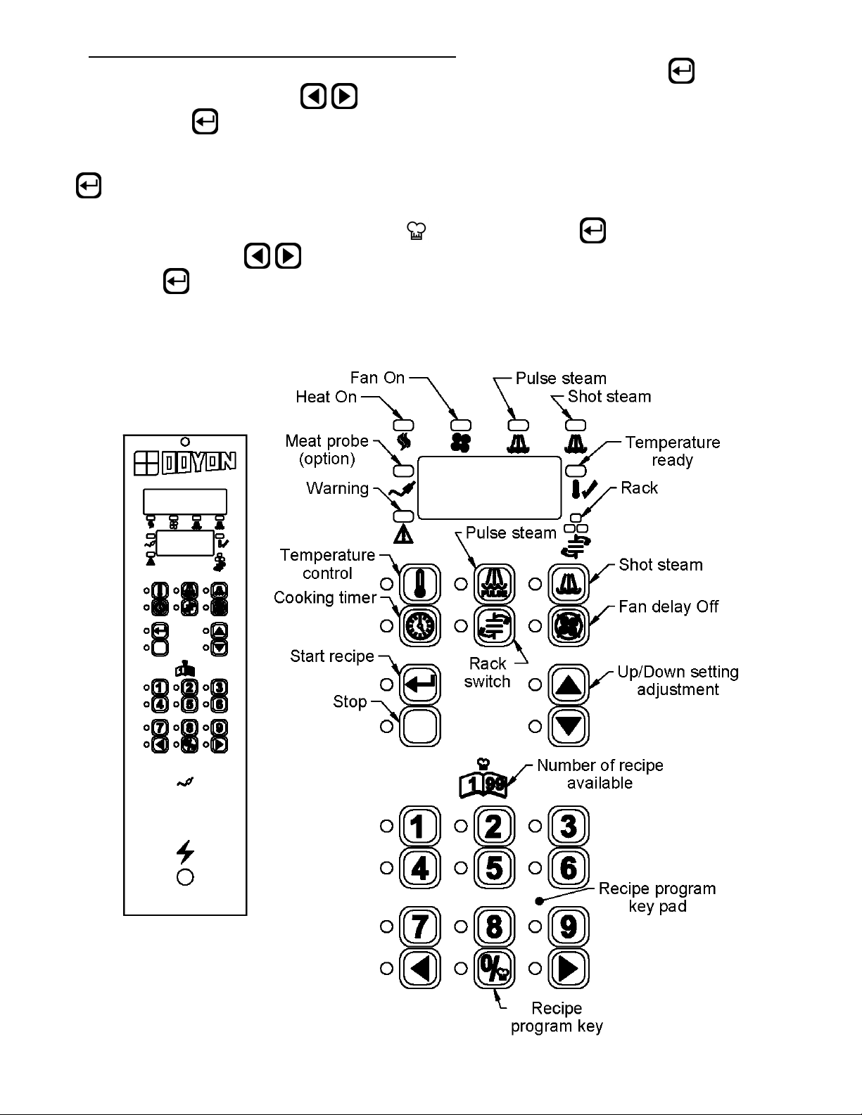
ECM-1 PROGRAMMABLE CONTROL - OPERATING MODES
The Doyon ECM-1 controller has two operation modes Manual and Programmable.
MANUAL: to use all functions without using recipe program.
PROGRAMMABLE: to use with recipe cook program.
Program capacity
□ Programs #1 to #99 can have up to 10 steps each (low-level programmable).
□ Program #0 is always used as the default Manual Cook mode setting (single-step).
OFF MODE
Display/LED
□ Display shows OFF.
□ All other LEDs are off, except the
Press on (start) when the oven is ON, the oven will run on preheat mode at the manual mode set
point (except if you select a cook program referred in How to Select a Cook Program or the Manual
Mode section).
To switch the oven OFF Press the RED stop button and hold it for 3 seconds. The oven will run on
cool down mode until it reaches 250°F and then switch OFF.
To change the temperature set point or timer setting press and hold for 3 sec. on
appears on the left side of the display, press on / (up / down) to select the desired
temperature set point or timer setting. The new set point or time setting will be automatically saved
after 3 seconds.
Display/LED
□ Display scrolls current cook program name (by default MANUAL if no program yet
selected).
□ 2nd line shows actual oven temperature.
□ Heat and Fan, LED follows output state.
□ Ready LED blinks.
□ Stop LED is on.
This is the default mode when the controller powers up.
Start key LED.
or
. When
When probe temperature reaches set point, the unit beeps 5 seconds, the ready LED stays on and the
oven goes into COOK MODE.
When the oven is ON, a 3 second long press of red Stop key will go to Cool Down mode if the oven
temperature is over 250°F / 120°C before going to OFF mode. If the temperature is bellow 250°F /
120°C, the oven goes directly to the OFF mode.
DOOR SWITCH
□ If door is opened:
○ Display scrolls DOOR OPEN.
○ All outputs are turned off (unless in Cool Down mode, then fan remains on).
○ All timers pause until the door is closed.
□ When the door is closed, a short delay must expire before all accessories resume normal
operation.
Page 11
A-8
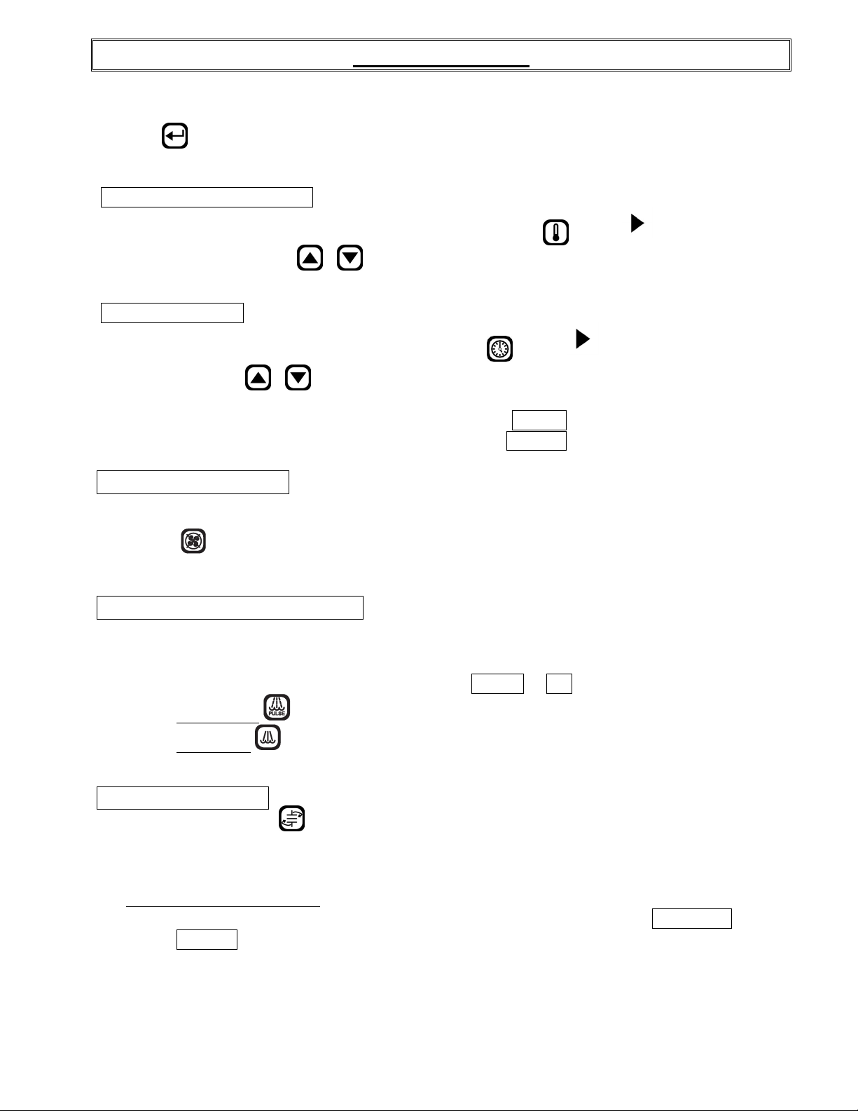
How to select a cook program or the Manual Mode
To select a recipe program, enter the recipe number with the numeric keypad and press (Start) or
use the Next or Previous arrow
confirm with the (Start) key.
When the recipe is selected, it will be active in the preheat mode until the set point in the first step is
reached. The LED of the red Stop key will light. The recipe will start only when the LED of the key
(Start) is lit.
To go back to the Manual Mode, press on the key and then on the (Start) key or use the
Next or Previous arrow
with the key (Start).
to jump from one to an other program without having to confirm
to jump from one to an other program without having to
Page 12
A-9
MANUAL MODE
This mode is used to work one step program.
Press on (Start) when the oven is ON, the oven will run on preheat mode at the manual mode set
point (by exception if you select a cook program referred in the PROGRAM MODE section).
TEMPERATURE FUNCTION
To change the temperature set point, press and hold for 3 sec. on . When
side of the display, press on / (Up / Down) to select the desired temperature set point. The
new set point will be automatically saved after 3 seconds.
TIMER FUNCTION
To change the time setting, press and hold for 3 sec. on
the display, press on / (Up / Down) to select the desired time setting. The new time setting
will be automatically saved after 3 seconds.
□ If time is less than 60 minutes, it will be displayed as MM.SS
□ If time is 60 minutes or more, it will be displayed as HH:MM
FAN DELAY FUNCTION
□ The fan is always in function, but you can delay the fan for 5 minutes by pressing the Delay
key . After 5 minutes, the fan will run normally. By pressing a second time on the key
before the end of the delay, the fan will remain in function.
STEAM GENERATION FUNCTION
When
.
appears on the left side of
appears on the left
□ Steam output can be turned on only if oven’s temperature >= steam threshold
(300°F /149°C).
□ Steam output can be turned on only if fan is on PULSE
○ Pulse Steam
○ Shot steam : steam output is turned on for duration of preset time.
□ Note: Steam and Pulse-Steam in Manual Mode will force Fan On.
FUNCTION CHARIOT
This function is available only with ovens using a rotating rack. This function allows to start and
stop the rack.
Food Probe in Manual Mode
○ When activated, the food probe temperature can only be used in mode MONITOR
ONLY. This will indicate the internal food temperature, not the cooking. To control
cooking, use the Programming mode.
: will turn on and off the steam output continuously if pressed again.
or ON.
Page 13

A-10
PROGRAM MODE
This mode is used to program a Cook Recipe.
Cook Program structure
A cook program consists of a name as well as a number of steps. The name is pre-programmed into
the unit (each name can have up to 30 characters). Each step has the following programmable
parameters:
Oven temperature: the oven set point for this step.
Food temperature: the food temperature at which this step will end.
Time: the time duration for the current step.
Steam: the time steam is injected into the oven at the beginning of the step.
Fan: fan mode.
Aux.: on or off during step (only programmable via PC).
Rack: on or off during step.
Step End: user action needed at the end of step.
Programming
LED/Display
□ 1st line displays currently selected parameter’s value.
□ 2nd line displays current step.
Keys
□ To program or modify a recipe program, select the recipe name first, press and hold for 3
seconds on the Program key. This will give you access to the recipe program. If no
change is made in the recipe during more than 5 seconds, the controller will exit the recipe
program mode by itself and go back to standby mode.
□ All parameters can be programmed in any order within a step.
To program or modify a recipe, follow these steps :
□ Use the parameter keys (Temperature, Time, Steam, Pulse-Steam, Fan, Rack, or Step End) to
display and change its value.
○ Temperature key is used twice to program 2 parameters: Oven Set Point and Food
Temperature.
□ Use the Up / Down keys to change the current parameter.
□ Use the Previous / Next keys to change the current step number.
□ If Step End key is set to LAST
more steps may follow in the program.
□ After last step is programmed, hold the Program key for 3 seconds to exit programming
mode.
Valid programming ranges
Temperature
□ 50-500°F / 10-260°C
Food Temperature
□ 125-225°F / 51-107°C, must be enabled in Low-level programming to be used.
Time
□ Time is programmed in HH:MM.SS
□ Time can be programmed at any value between 00:00 minimum and 12:00 maximum.
□ Default is 00:00 for all steps / programs.
, it is considered to be the last step of the program even though
Page 14

A-11
Steam
□ 1st parameter can be: OFF, ON, PULSE.
○ If OFF, steam remains off for duration of step.
○ If ON, steam remains on for duration of step.
○ If PULSE, pulsed steam is enabled for duration of step.
□ Default is OFF for all steps / programs (no steam).
Pulse-Steam
□ Steam parameter (see above) must be set to PULSE.
□ Pressing Pulse-Steam allows programming TON 0.02 seconds by default.
□ Pressing Pulse-Steam a 2nd time allows programming TOFF 0.30 seconds by default.
□ Default is OFF for all steps / programs (no steam).
Fan
□ 1st parameter can be: OFF, ON, PULSE.
○ If OFF, fan remains off for duration of step.
○ If ON, fan remains on for duration of step.
○ If PULSE
, pulse fan is enabled (pulse mode for duration of step).
■ Pressing Fan a 2nd time allows programming TON 02.30 minutes by default.
■ Pressing Fan a 3
rd
time allows programming TOFF from 0.25 seconds by default.
□ Default is PULSE for all steps/programs.
Rack
(Functional only with oven models with rotating racks).
□ Rack must be enabled in low-level programming to be useable.
□ This can be ON or OFF for each step.
□ Default is ON for all steps / programs, if enabled in low-level programming.
Step End
□ Step End defines what happens with the end of a Cook Program Step (Stop key is used to
program Step End parameter).
○ AUTO: nothing happens, automatically move on to the next step (buzzer output remains
off).
○ WARN: move on automatically to the next step, but turn on buzzer output for 5 seconds.
○ MANUAL: activates buzzer output until user manually presses Start key to enable next
step.
○ LAST: activate buzzer output until user manually presses Stop key to end the recipe.
□ Default is AUTO
for all steps / programs.
Food Probe in Programming Mode
□ Food temperature can be programmed to the following settings OFF ON MONITOR.
○ ON
: using food temperature’s programming set point to end the current step at that
temperature.
○ OFF: default for all steps / programs.
○ MONITOR
: to ignore food probe temperature, but still display the information if
requested.
Page 15

A-12
COOK MODE
reminder, this mode can cook without using the timer.
Display/LED
□ The 1st line display depends on which view is selected:
○ Time View
○ Temperature View
○ Default View:
□ 2nd line shows current step number if oven is active.
□ Heat, Fan, Steam LED follows output state.
Keys
□ Note : Any changes to the various oven parameters in this mode will not be stored, but will
□ Press Temperature key to toggle the current view between Default, Cavity Probe and Food
Probe.
□ Press Time key:
○ Recipe active: toggles between default and remaining step time.
○ Last Step: toggles between the default and holding time.
□ 3-second long press of Temperature key to change set point (using Up/Down keys).
○ If enabled, a second press of the Temperature key will display the food probe setting.
□ 3-second long press of Time key to change timer’s value (using Up/Down keys).
□ Press Start key to start timer countdown (and rack rotation, if enabled).
□ 3-second long press of Next key to skip to next step.
□ 3-second long press of Previous key to go back to previous step.
□ Press Stop key to cancel countdown and return to idle.
□ 3-second long press of Stop key to go into Cool Down mode.
□ In Manual Mode only, Fan, Rack, Steam and Auto-Steam keys can be used to toggle their
respective output states.
□ Auto-Steam key will start/stop the auto-steam according to Low-level Steam Override TON
and TOFF parameters.
□ If oven is idle, a 5-second long press of the
the currently selected Cook Program (or Manual Program).
□ When last step timer expires, the unit beeps 5 times and displays PRODUCT READY.
Pressing Stop red key will clear the message and resume idle.
When a Cook Program is used, if the timer is inactive, the oven is considered idle
(but it still maintains the set point). In Manual Mode, the timer is used only as a
■ Current time left in step is displayed, except in the last step, where hold time is
displayed.
■ Cavity temperature.
■ Current program name is displayed, except in last step, where PRODUCT READY
displayed.
simply take effect in the current step. This allows “tweaking” recipes from time to
time due to product variations or other factors. For changes to be stored, program
mode must be used.
Program key will enable Program Mode for
is
Page 16

A-13
SYSTEM DIAGNOSTICS
Cavity Probe Alarm
□ Occurs when units detects a defective cavity or food temperature probe.
□ Unit goes into Off mode with error message CAVITY PROBE ERROR or
FOOD PROBE ERROR.
Accessory Failure
□ Occurs when input signal is no longer received.
□ Unit goes into Off mode with error message:
○ Accessory failure input # generates ACCESSORY 1 FAILURE.
○ Accessory failure input # generates OVERHEAT FAILURE over heat alarm in control
compartment (check cooling fan and filter).
LANGUAGE DISPLAY
Three languages are available. To change the language display, the controller must be at OFF mode.
Press and hold the key for 5 seconds and use
□ENGLISH, FRANCAIS, ESPANOL
Only the following message will be changed, you can only change the recipe name by using a PC.
/ keys to select the language.
□ English French Spanish
OFF ARRÊT APAGADO
ON MARCHE MARCHA
PULSE IMPULSION IMPULSO
AUTO AUTOMATIQUE AUTOMATICO
WARN AVERTISSEMENT ADVERTENCIA
MANUAL MANUEL MANUAL
LAST DERNIER ULTIMO
MONITOR MONITEUR MONITOR
COOLING DOWN REFROIDISSEMENT ENFRIAMIENTO
ECONOMY MODE MODE ECONOMIQUE MODO ECONOMICO
DOOR OPEN PORTE OUVERTE PUERTA ABIERTA
PRODUCT READY PRODUIT PRET PRODUCTO LISTO
CAVITY PROBE ERROR ERREUR DE SONDE DE ERROR SONDA DE
CAVITE CAVIDAD
FOOD PROBE ERROR ERREUR DE SONDE DE ERROR SONDA DE
NOURRITURE ALIMENTOS
ACCESSORY FAILURE 1 ECHEC ACCESSOIRE 1 FALLA ACCESORIO 1
ACCESSORY FAILURE 2 ECHEC ACCESSOIRE 2 FALLA ACCESORIO 2
Page 17

CONTRÔLE PROGRAMMABLE ECM-1 - MODES D'OPÉRATION
Le contrôleur ECM-1 Doyon est doté du mode de fonctionnement manuel et programmable.
MANUEL : pour l’utilisation des fonctions sans avoir de recettes à programmer.
PROGRAMMABLE : ce mode est utilisé pour programmer une recette de cuisson.
Capacité du programme
□ Le programme #0 est toujours utilisé comme programme par défaut du mode Cuisson
Manuel (une seule étape).
□ Les programmes de #1 à #99 peuvent contenir jusqu'à 10 étapes de fonctionnement par
recette.
A-14
MODE ARRET
État d'affichage & DEL
□ L'écran affiche ARRET
□ Toutes les autres DEL sont éteintes, sauf celle de la touche
En appuyant sur (départ) quand le four est en marche, le four se met en mode préchauffage sur
le point de consigne du mode manuel sauf si un programme est sélectionné au préalable (voir plus
bas comment sélectionner une recette ou le Mode Manuel).
Pour mettre le four à l'arrêt appuyer sur le bouton rouge pendant 3 sec. Le four va se mettre en
mode de refroidissement et s'arrêter lorsque la température de la chambre atteindra 250°F.
Pour changer le degré de température ou le temps désiré, appuyez 3 sec. sur
apparaît à gauche de l'affichage, appuyez sur / (haut / bas) pour choisir le degré de
température et le temps désiré. La nouvelle consigne va s’enregistrer automatiquement après 3
secondes.
État d'affichage & DEL
□ L'écran défile le nom du programme de cuisson en cours (par défaut MANUEL si aucun
programme n'a été sélectionné).
□ La 2e ligne affiche la température actuelle du four.
□ Chaleur et Ventilateur, les DEL suivent l'état de leur sortie.
□ La DEL Prêt clignote.
□ La DEL Arrêt est allumée.
Fonction par défaut lors de l'alimentation
(départ).
ou
. Lorsque
Lorsque la température du four atteint le point de consigne, l'unité bip-bip pendant 5 secondes et
lorsque la DEL Prêt reste allumée et ne clignote plus, le four est prêt à être utilisé en MODE
CUISSON.
En appuyant 3 secondes sur la touche (arrêt rouge) quand le four est en marche, le Mode de
Refroidissement s'active si la température interne du four est supérieure à 250°F /120°C avant de
se mettre en MODE ARRÊT. Si la température est inférieure à 250°F /120°C, le four se met
immédiatement en MODE ARRÊT.
OUVERTURE DES PORTES
□ Si la porte est ouverte :
○ L'écran d'affichage défile PORTE OUVERTE.
○ Toutes les sorties ne sont pas en fonction.
○ Toutes les minuteries s'arrêtent et ne poursuivent que lorsque la porte est fermée.
□ Tous les accessoires reprennent leur état initial quelques secondes après avoir refermé la
porte.
Page 18

A-15
Comment sélectionner une recette programmée ou le Mode Manuel
Pour choisir une recette programmée, entrez le numéro de la recette à l'aide du clavier numérique et
appuyez sur (départ ou utilisez les flèches
avoir à le confirmer avec la touche (départ).
Lorsque la recette est choisie, elle s'active en mode préchauffage selon la programmation de la
recette. La DEL de la touche (arrêt rouge) est donc allumée et la recette ne peut être activée
seulement lorsque la DEL de touche
(départ) est allumée.
pour sauter d'un programme à l'autre sans
Pour revenir au Mode Manuel, appuyez sur la touche
pour sauter du programme sélectionné au programme manuel sans avoir à le confirmer
avec la touche (départ).
et sur (départ) ou utilisez les flèches
Page 19

MODE MANUEL
Ce mode est employé pour l’utilisation des fonctions sans avoir de recettes à programmer.
FONCTION TEMPÉRATURE
A-16
Pour changer le degré de température désiré, appuyez 3 sec. sur . Lorsque
gauche de l'affichage, appuyez sur / (haut / bas) pour choisir le degré de température
désiré. La nouvelle consigne devrait s’enregistrer automatiquement après 3 secondes.
FONCTION MINUTERIE
Pour changer le temps de cuisson, appuyez 3 sec. sur
l'affichage, appuyez sur
consigne devrait s’enregistrer automatiquement après 3 secondes.
□ Si le temps est moins que 60 minutes, le temps est affiché dans le format MM.SS
□ Si le temps est de 60 minutes ou plus, le temps est affiché dans le format HH:MM
FONCTION DELAI VENTILATEUR
□ Le ventilateur est toujours en fonction. Par contre, si l'utilisateur appuie sur la touche délai
ventilateur , le ventilateur s'arrêtera pour une période de 5 minutes. En appuyant une
seconde fois, le ventilateur se remet en fonction.
FONCTION GÉNÉRATION DE VAPEUR
/ (haut / bas) pour ajuster le temps de cuisson. La nouvelle
Lorsque
.
apparaît à gauche de
apparaît à
□ La sortie Vapeur peut être activée seulement si la température du four ≥ (300ºF / 149ºC).
□ La génération de vapeur peut se faire de 2 façons :
○ Vapeur pulsée : la sortie Vapeur commute continuellement pour la durée de l'étape
en mode programmation ou jusqu'à ce qu’on appuie à nouveau sur Vapeur Automatique
en Mode Manuel.
○ Injection unique à demande : la sortie Vapeur est activée pour la durée préréglée.
□ Note: La vapeur pulsée ou la vapeur à la demande force le ventilateur à fonctionner.
FONCTION CHARIOT
Cette fonction est utilisée pour les modèles de four avec chariot rotatif seulement et permet d'activer
ou désactiver le chariot.
Sonde de nourriture en Mode Manuel
□ La température de la sonde de nourriture si activée peut être utilisée en mode MONITEUR
seulement. Ceci indique la température interne de la nourriture, mais ne contrôle pas la
cuisson. Pour contrôler la cuisson, il faut utiliser le mode programmable.
Page 20

A-17
MODE PROGRAMMABLE
Ce mode est utilisé pour programmer une recette de cuisson.
Structure d'un Programme de Cuisson
Un Programme de Cuisson consiste donc en un nom de recette qui est préenregistré dans le contrôle
(chaque nom peut contenir jusqu'à 30 caractères, PC requis). Les paramètres suivants peuvent être
programmés pour chacune des étapes d'une recette :
Température four : point de consigne du four pour cette étape.
Température nourriture : température de la sonde de nourriture où l'étape prendra fin.
Temps : la durée de l'étape en cours.
Vapeur : la durée de l'injection de vapeur à partir du début de l'étape.
Ventilateur : mode Ventilateur.
Aux. : activé ou désactivé durant l'étape (PC requis).
Plateau tournant : activé ou désactivé durant l'étape.
Fin d'étape : intervention de l'utilisateur requise à la fin de l'étape.
Programmation
Affichage / DEL
□ La 1
□ La 2
Touches
□ Pour programmer ou modifier une recette, sélectionnez le numéro de la recette désirée,
□ Aucun ordre particulier est nécessaire pour la programmation des paramètres dans une
ère
ligne affiche la valeur du paramètre sélectionné à l'aide de la touche.
ème
ligne affiche l'étape en cours.
maintenez la touche Programme pendant 3 secondes pour avoir accès à la
programmation de la recette. Pendant la programmation, si aucune touche est utilisée après
5 secondes, le contrôleur retournera de lui-même en mode attente.
étape.
Pour programmer ou modifier une recette suivre les étapes suivantes:
□ Utilisez les touches de paramètres (Température, Minuterie, Vapeur, Vapeur Automatique,
Ventilateur, Plateau ou Fin Étape) pour afficher et changer sa valeur.
○ La touche Température est utilisée à 2 reprises pour programmer 2 paramètres : point
de consigne du four et température de la sonde de nourriture si activée.
□ Utilisez les touches Haut / Bas pour modifier la valeur du paramètre en cours.
□ Utilisez les touches Précédent / Suivant pour changer de numéro d'étape.
□ Si la touche Fin Étape est réglée à DERNIER, c'est considéré comme étant la dernière étape
du programme même si d'autres étapes suivent dans le programme.
□ Après la programmation de toutes les étapes, maintenez la touche Programme pendant 3
secondes pour quitter le mode programmation.
Plages de valeurs permises
Température
□ 50-500°F/10 -260°C
Température de la sonde de nourriture
□ 125-225°F / 51-107°C, doit être activée dans la programmation de bas niveau afin d'être
utilisée.
Temps
□ Le temps est programmé sous le format HH : MM.SS.
□ Le temps peut être programmé à toutes les valeurs entre 00:00 minimum et 12:00 heures
maximum.
□ Le temps par défaut est 00:00 pour tous les programmes / étapes.
Page 21

Vapeur
□ Pour le 1er paramètre, les choix sont : MARCHE, ARRET, PULSE.
○ ARRET : la vapeur reste fermée pour toute la durée de l'étape.
○ MARCHE : la vapeur reste active pour toute la durée de l'étape.
○ PULSE
□ ARRET
: la vapeur est pulsée pour toute la durée de l'étape.
: par défaut pour toutes les étapes / programmes (pas de vapeur).
Vapeur-Pulsée
□ Le paramètre de Vapeur doit être réglé à PULSE.
□ Appuyer sur la touche Vapeur-pulsée permet de programmer TON 0.02 secondes par défaut.
□ Appuyer sur touche Vapeur-pulsée une 2
ème
fois permet de programmer T
0.30 secondes
OFF
par défaut.
□ ARRET par défaut pour toutes les étapes / programmes (pas de vapeur pulsée).
Ventilateur
□ Pour le 1er paramètre, les choix sont : MARCHE, ARRET, PULSE
○ ARRET : le ventilateur est arrêté pour toute la durée de l'étape.
○ MARCHE : le ventilateur tourne pour toute la durée de l'étape.
○ PULSE : le ventilateur tourne à intermittence pour toute la durée de l'étape.
■ Appuyer sur la touche Ventilateur une 2
ème
fois permet de programmer TON du
ventilateur 2.30 minutes par défaut.
ème
■ Appuyer sur la touche Ventilateur une 3
ventilateur 0.30
par défaut.
fois permet de programmer T
□ PULSE par défaut pour toutes les étapes / programmes.
Chariot
(pour les modèles de four avec chariot rotatif seulement)
□ Afin de pouvoir utiliser le Chariot, ce dernier doit être activé dans la programmation de Bas
Niveau.
□ Le Chariot peut prendre l'état MARCHE ou ARRET pour chacune des étapes.
□ Le Chariot prend l'état MARCHE par défaut pour toutes les étapes / programmes si activé
dans la programmation de Bas Niveau.
Fin D'étape
□ Étape Fin défini ce qui se produit avec l'avertisseur à la fin d'une étape d'un Programme de
Cuisson ( la touche arrêt est utilisée pour programmer le paramètre Étape Fin ).
○ AUTOMATIQUE
: rien ne se passe, allez directement à l'étape suivante ( l'avertisseur ne
se fait pas entendre ).
○ AVERTISSEMENT
: passe directement à l'étape suivante, mais l'avertisseur émet un
bruit pour une période de 5 secondes.
○ MANUEL
: l'avertisseur se fait entendre jusqu'à ce que l'utilisateur appuie sur la touche
de départ, déclenchant du même coup le passage à l'étape suivante.
○ DERNIER : l'avertisseur se fait entendre jusqu'à ce que l'utilisateur appuie sur la touche
arrêt, mettant ainsi fin au Programme de Cuisson.
○ AUTOMATIQUE
: par défaut pour toutes les étapes / programmes.
OFF
A-18
du
Sonde de nourriture en mode programmable
□ La Température de la sonde de nourriture peut être programmée des manières suivantes :
○ MONITEUR : indique la température interne de la nourriture, ne contrôle pas la
cuisson.
○ ON : prend charge de la cuisson et lorsque la température interne de la nourriture
atteint sa consigne définie dans la recette, elle met fin à la recette.
○ OFF
par défaut pour toutes les étapes / programmes.
Page 22

A-19
MODE CUISSON
Fonction par défaut lors de l'utilisation d'un Programme de Cuisson (ou Mode
Manuel). Si la minuterie n'est pas active, le four est considéré inactif (mais le
point de consigne est maintenu).
Affichage/DEL
□ L'affichage sur la 1
ère
ligne de l'écran dépend du type d'affichage sélectionné:
○ Temps
■ Un compte à rebours est affiché pour chacune des étapes, sauf pour la dernière étape
où c'est le temps de maintien qui est affiché.
○ Température
■ Température de la cavité.
○ Par défaut:
■ Le nom du programme en cours est affiché, sauf à la dernière étape, où PRODUIT
PRET est affiché.
□ La 2
ème
ligne affiche le numéro de l'étape en cours si le four est activé.
□ Les DEL Chaleur, Ventilateur et Vapeur suivent l'état de leur sortie.
Touches
□ Note : Dans ce mode, tout changement effectué sur les différents paramètres du four ne
seront pas conservés, mais prendront effet uniquement pour l'étape en cours. Cela
permet un ajustement ponctuel des recettes pour palier aux variations du produit et
facteurs divers. Le Mode Programmation doit être utilisé si les changements sont à
garder en mémoire.
□ L'affichage bascule entre Défaut, Sonde de cavité et Sonde de nourriture si activée en
appuyant sur la touche température.
□ En appuyant sur la touche de minuterie :
○ Recette active : bascule entre l'affichage par défaut et compte à rebours (étape).
○ Dernière étape : bascule entre l'affichage par défaut et le temps de maintien.
□ Le changement du point de consigne s'effectue en appuyant 3 secondes sur la touche
température (modifiez la température à l'aide des touches haut / bas).
○ Si activée, une seconde pression sur la touche température permet d'afficher l'ajustement
de la sonde de nourriture.
□ L'ajustement de la minuterie s'effectue en appuyant 3 secondes sur la touche de minuterie (à
l'aide des touches haut / bas).
□ Le compte à rebours de la minuterie (et la rotation du plateau, si activée) débute en
appuyant sur la touche départ.
□ Pour passer directement à l'étape suivante, appuyez 3 secondes sur la touche Suivant.
□ Pour revenir à l'étape précédente, appuyez 3 secondes sur la touche Précédent.
□ Pour annuler le compte à rebours et retourner à la température de maintien, appuyez sur la
touche Arrêt.
□ Le mode de Refroidissement s'active en appuyant 3 secondes sur la touche d'Arrêt.
□ En mode Manuel seulement, les touches Ventilateur, Plateau, Vapeur et Vapeur Automatique
peuvent être utilisées pour basculer vers leurs états respectifs.
□ La touche Vapeur Automatique va démarrer / arrêter la vapeur selon les paramètres TON et
TOFF selon le niveau de vapeur.
□ Si la température du four est en maintien, l'activation du Mode Programmation pour le
Programme de Cuisson (ou Programme Manuel) venant d'être sélectionné s'effectue en
appuyant 5 secondes sur programme
.
□ Lorsque le compte à rebours de la dernière étape se termine, l'unité émet 5 bips et affiche
PRODUIT PRÊT
. Si la touche minuterie est active, le compte à rebours indique la période
écoulée depuis la fin de la recette. En appuyant sur la touche (arrêt rouge), le message et le
temps s'efface et la température de maintien est conservée.
Page 23

A-20
DIAGNOSTIQUE DU SYSTÈME
Alarme de sonde de cavité
□ Survient lorsque l'unité détecte une défectuosité en ce qui concerne la sonde de cavité ou la
sonde de nourriture.
□ L'unité se met en mode Arrêt et affiche le message ERREUR DE SONDE DE CAVITE ou
message ERREUR DE SONDE DE NOURRITURE
Défectuosité accessoire
□ Survient lorsque l'unité ne reçoit plus le signal d'entrée pour un accessoire donné.
□ L'unité se met en mode Arrêt et affiche le message :
ECHEC ACCESSOIRE # (# correspond au numéro de l'accessoire en cause).
ECHEC SURCHAUFFE alarme de surchauffe dans le compartiment de contrôle (Vérifiez
ventilateur de refroidissement et filtre).
LANGUE D'AFFICHAGE
POUR CHANGER LA LANGUE D'AFFICHAGE
Trois langues sont disponibles. Pour changer la langue d'affichage, mettre le four en mode ARRÊT.
Ensuite, appuyez et maintenez la touche pour 5 secondes et appuyez sur les touches /
pour changer la langue. □ENGLISH, FRANCAIS, ESPANOL seulement les messages de l'interface
ci bas seront changés, les noms de recettes doivent être fait à partir d'un PC.
□ English French Spanish
OFF ARRÊT APAGADO
ON MARCHE MARCHA
PULSE IMPULSION IMPULSO
AUTO AUTOMATIQUE AUTOMATICO
WARN AVERTISSEMENT ADVERTENCIA
MANUAL MANUEL MANUAL
LAST DERNIER ULTIMO
MONITOR MONITEUR MONITOR
COOLING DOWN REFROIDISSEMENT ENFRIAMIENTO
ECONOMY MODE MODE ECONOMIQUE MODO ECONOMICO
DOOR OPEN PORTE OUVERTE PUERTA ABIERTA
PRODUCT READY PRODUIT PRET PRODUCTO LISTO
CAVITY PROBE ERROR ERREUR DE SONDE DE ERROR SONDA DE
CAVITE CAVIDAD
FOOD PROBE ERROR ERREUR DE SONDE DE ERROR SONDA DE
NOURRITURE ALIMENTOS
ACCESSORY FAILURE 1 ECHEC ACCESSOIRE 1 FALLA ACCESORIO 1
ACCESSORY FAILURE 2 ECHEC ACCESSOIRE 2 FALLA ACCESORIO 2
Page 24

A-21
TROUBLESHOOTING
BEFORE CALLING FOR SERVICE
ANSWERS TO MOST FREQUENT QUESTIONS
Always cut off the main power before replacing any parts. Take care of water piping system
when servicing.
Control parts are under the left front bottom panel and under the control panel.
Remove the front panels by screwing out the only screw on each panel.
Questions Solutions
The oven temperature drops when loading
and needs a certain amount of time before it
stabilizes.
The oven does not turn on.
The oven does not produce heat.
This is normal. The opening of the door produces
an important loss of heat. The rack loaded with
cold pastries need a large amount of heat to get
back to its original temperature. The same thing
happens with domestic ovens. You will realize
that your new TLO electric oven can provide an
excellent baking quality for any kind of products
you want to bake.
If the oven is turned on for the first time and
nothing happens, just reverse the two phases
feeders in the main supply box. A phase
sequence relay is installed on the oven to avoid
burner fan to turn in the wrong direction.
If the oven has already functioned, check the
motor fuses and the overload relays located in the
electrical control panel. Turn the main power off
to replace the fuses.
Make sure that the door is closed and the
thermostat adjusted to the desired
temperature. (You can hear the oven
blowers).
The steam system does not react correctly.
If the oven blowers are not on, check the
overload relays located in the control
compartment. If anyone of these is
disengaged, call for a qualified technician.
Check if the water supply is connected and the
input valve opened.
Call for a qualified electrician or plumber if
required..
Page 25

A-22
DÉPANNAGE
AVANT D'APPELER LE DÉPARTEMENT DE SERVICE
SOLUTION AUX PROBLÈMES LES PLUS FRÉQUENTS
Toujours fermer l'approvisionnement du courant principal avant le remplacement de pièces.
Prendre garde aux tuyaux d'eau avant de déplacer le four.
Les pièces de contrôle sont sous le panneau gauche à l’avant du four et sous le panneau de
contrôle.Enlever le panneau en dévissant la seule vis qui maintient chaque panneau.
Problèmes Solutions
La température du four baisse lors de
l'enfournage et prend un certain temps avant de
se stabiliser.
Le four ne réagit pas lors de la mise en marche.
C’est normal. L'ouverture de la porte fait entrer
une grande quantité d'air froid dans le four. Le
chariot chargé de pâtisseries froides nécessite
une quantité considérable de chaleur avant que
le four ne se stabilise à la température préréglée.
Le même phénomène se produit dans les fours
domestiques. Vous constaterez la très haute
qualité de cuisson réalisée avec votre four TLO
électrique pour les divers types de pâtisseries
Si le four est mis en marche pour la première
fois, il se peut que ce soit la séquence des phases
qui soit inversée. Un relais de détection de la
séquence des phases et de la perte d'une phase
est installé sur le four. Inverser deux conducteurs
de phase et essayer de nouveau.
Si le four a déjà fonctionné, vérifier les fusibles
de moteur et les relais de surcharge situés dans
le compartiment de contrôle du four en bas près
de la porte. Fermer l’approvisionnement du
courant principal avant de remplacer les
fusibles.
Le four ne produit pas de chaleur.
Le système de vapeur ne répond pas comme il se
doit.
1. Si les moteurs tournent:
•
Assurez-vous que le thermostat est ajusté à
une température suffisamment élevée pour
faire allumer la lampe témoin.
2. Si les moteurs ne tournent pas:
•
Vérifier les relais de surcharge situés dans la
boîte de contrôle. Si un des relais n'est pas
engagé, appeler un technicien qualifié.
Vérifier si l'entrée d'eau est bien connectée et la
valve d'entrée ouverte.
Contacter un électricien ou un plombier qualifié
si nécessaire.
Page 26

A-23
OVEN MAINTENANCE AND CLEANING
Questions Solutions
Clean the inside of the oven and the proofer
with water and soap.
After cleaning the inside of the oven, apply a
silicone base oven protector. It avoids food
from sticking to the metal.
Clean the oven windows with products like
Brasso or equivalents. They are copper
cleaners but good for this use
Clean the oven exterior with a stainless steel
cleaner.
We recommend and sell:
Dirt Buster III: Action foam cleaner
CHEMCO
Part number: NEB201
We recommend and sell:
316 Silicone base protector and lubricant for
oven
Dow Corning
Part number : EXS400
We recommend and sell:
Wright's: Cream copper cleaner
J.A. Wright & Co.
Part number : EXC300
We recommend and sell:
Stainless steel cleaner
SANY or CURTIS (comestible)
Part number : NES201
MAINTENANCE AND LUBRICATION
MAINTENANCE AND LUBRICATION OF THE OVEN :
¾ Grease regularly as shown in «Lubrication» section.
Use only grease provided with the oven.
¾ It is recommended to use a water filter to avoid accumulation of minerals inside the oven
during the use of the steam cycle.
Page 27

ENTRETIEN ET NETTOYAGE DU FOUR
Étape par étape Solutions
A-24
Nettoyer l'intérieur du four avec de l'eau et un
détergent.
Après avoir nettoyé l'intérieur du four,
appliquer un protecteur sur les parois et les
grilles. Le produit empêche les aliments de
coller sur les parois du four.
Nettoyer les vitres du four avec du Brasso ou un
produit équivalent. Bien que ce soit des
nettoyeurs à cuivre, ils s'avèrent très efficaces.
Nettoyer l'extérieur du four avec un produit
d'entretien pour l'acier inoxydable.
ENTRETIEN ET LUBRIFICATION
ENTRETIEN ET LUBRIFICATION DU FOUR :
¾ Une lubrification régulière devrait être faite tel qu’indiqué à la section «Lubrification».
Produit recommandé:
Dirt Buster III
Nettoyant à four à action moussante
No de pièce: NEB201
Produit recommandé:
Protecteur de silicone pour four
No de pièce: EXS400
Produit recommandé:
Nettoyeur pour vitres de four
No de pièce: EXC300
Produit recommandé:
Nettoyeur pour acier inoxydable
No de pièce: NES201
Utiliser uniquement la graisse fournie avec le four.
¾ Il est recommandé d'utiliser un filtre à eau pour éviter l'accumulation de particules de
calcaire ou de minéraux à l'intérieur du four pendant le cycle de vapeur.
Page 28

A-25
A-25
LUBICATION
LUBRIFICATION
Page 29

Page 30

B-1
B-1
SECTION B:
COMPONENT PARTS
PIÈCES COMPOSANTE
TLOI – FRONT VIEW
TLOI – VUE DE FACE
Page 31

B-2
Item Part Number Description Quantity
1 ELP407 EMERGENCY STOP RED BUTTON 40mm TURNS TO
RELEASE
2 ELI408 MOUNTING BASE ONLY 1
3 ELI409 CONTACT BLOCK NC 1
4 ELI556 0/1 PLATE 1
5 ELI419 ''EMERGENCY STOP'' PLATE 1
6 ELC481 NICKEL CAP 7/8" 1
7 ELB096 5A BREAKER 1
8 ELT539-K1 ETHERNET JACK ASSEMBLY 1
9 ELC800 SOLID STATE RELAY FOR WATLOW CONTROL 2
10 ELM760 COOLING FAN 120V 1
11 ELT681 THERMOSTAT KNOB 700°F 1
12 ELT620 THERMOSTAT BEZEL 1
13 ELT680 THERMOSTAT 700°F 1
14 ELC507 ELEMENT CONTACTOR 100A, COIL 120V 2
15 ELD050 INCANDESCENT LIGHT SOCKET 1
16 ELA350 HALOGEN BULB 100 W 120V 1
17 50001403 50001114 AND 50001118 ASS. 1
18 50001405 50001116 AND 50001119 ASS. 2
19 50001404 50001115 AND 50001118 ASS. 1
20 ELE195K ELEMENT BLOCK 208V 4667W (TLO1) 1
ELE196K ELEMENT BLOCK 240V 4667W (TLO1) 1
ELE210K ELEMENT BLOCK 400V 4667W (TLO1) 1
ELE199K ELEMENT BLOCK 600V 4667W (TLO1) 1
1
Item Numéro Pièce Description Quantité
1 ELP407 ARRÊT D'URGENCE 40mm TOURNE POUR RELÂCHER
ROUGE
2 ELI408 BASE SANS CONTACT 1
3 ELI409 BLOC CONTACT NC 1
4 ELI556 PLAQUED'IDENTIFICATION 0/1 1
5 ELI419 PLAQUE ''EMERGENCY STOP'' 1
6 ELC481 BOUCHON 7/8" NICKEL 1
7 ELB096 DISJONCTEUR 5A 1
8 ELT539-K1 PRISE ETHERNET ASSEMBLÉE 1
9 ELC800 RELAIS STATIQUE POUR CONTRÔLE WATLOW 2
10 ELM760 VENTILATEUR DE REFROIDISSEMENT 120 V 1
11 ELT681 BOUTON DE THERMOSTAT 700°F 1
12 ELT620 PLAQUE DE THERMOSTAT 1
13 ELT680 THERMOSTAT 700°F 1
14 ELC507 CONTACTEUR D'ÉLÉMENT 100A, BOBINE 120V 2
15 ELD050 BASE DE LUMIÈRE 1
16 ELA350 AMPOULE HALOGÈNE 100 W 120V 1
17 50001403 ASS. 50001114 ET 50001118 1
18 50001405 ASS. 50001116 ET 50001119 2
19 50001404 ASS. 50001115 ET 50001118 1
20 ELE195K BLOC ÉLÉMENT 208V 4667W (TLO1) 1
ELE196K BLOC ÉLÉMENT 240V 4667W (TLO1) 1
ELE210K BLOC ÉLÉMENT 400V 4667W (TLO1) 1
ELE199K BLOC ÉLÉMENT 600V 4667W (TLO1) 1
1
Page 32

B-3
B-3
TLOII – TOP VIEW
TLOII – VUE DE DESSUS
Page 33

Item Part Number Description Quantity
1 ELP900 SPLITTER BOX 225A 4P 1
2 ELM820TL LEROY SOMER MOTOR 3PH 3/4HP 230/460V 1
3 ELV590 NEEDLE VALVE 1
4 ELS887 SOLENOID VALVE WITH DIN CONNECTION
110/120V 50/60HZ
5 ELS889 JONCTION BOX FOR ELS887 & ELS888 1
6 PLF100 WATER FILTER 1
7 ELM765 GEARBOX MOTOR 1/8HP 1PH 115V 1
8 QUC800 V BELT 52" 1
9 ELM595 MICRO SWITCH (RACK) 1
10 QUC310 ROLLER CHAIN #41 1
11 ELM575 MICRO SWITCH (DOOR) 1
Item Numéro Pièce Description Quantité
1 ELP900 PANNEAU DE RÉPARTITION 225A 4 PÔLES 1
2 ELM820TL MOTEUR LEROY SOMER 3PH 3/4HP 230/460V 1
3 ELV590 VALVE À POINTEAU 1
4 ELS887 VALVE À SOLENOÏDE AVEC CONNECTION DIN
110/120V 50/60HZ
5 ELS889 BOÎTE DE JONCTION POUR ELS887 ET ELS888 1
6 PLF100 FILTRE À EAU 1
7 ELM765 MOTEUR RÉDUCTEUR 1/8HP 1PH 115V 1
8 QUC800 COURROIE EN V 52" 1
9 ELM595 INTERRUPTEUR DE POSITION (CHARIOT) 1
10 QUC310 CHAÎNE #41 1
11 ELM575 INTERRUPTEUR DE POSITION (PORTE) 1
1
1
B-4
Page 34

B-5
B-5 B-5
RACK HLODER ASSEMBLY
SUPPORT DE CHARIOT
Page 35

B-6
B-6
Page 36

C-1
C-1
SECTION C:
CONTROL PANELS
PANNEAUX DE CONTRÔLE
TLO BREAK RACK PANEL
TLO PANNEAU ARRÊT CHARIOT
Page 37

C-2
C-2
TLO1 3PH 120/208 120/240V 60HZ
TLO1 3PH 120/208 120/240V 60HZ
Page 38

NOTES
Page 39

LIMITED WARRANTY
(Continental United States Of America And Canada Only)
Doyon Equipment Inc. guarantees to the original purchaser only that its product are
free of defects in material and workmanship, under normal use.
This warranty does not cover any light bulbs, thermostat calibration or defects due to
or resulting from handling, abuse, misuse, nor shall it extend to any unit from which
the serial number has been removed or altered, or modifications made by
unauthorised service personnel or damage by flood, fire or other acts of God. Nor will
this warranty apply as regards to the immersion element damaged by hard water.
The extent of the manufacturer’s obligation under this warranty shall be limited to the
replacement or repair of defective parts within the warranty period. The decision of
the acceptance of the warranty will be made by Doyon Equipment service
department, which decision will be final.
The purchaser is responsible for having the equipment properly installed, operated
under normal conditions with proper supervision and to perform periodic preventive
maintenance.
If any parts are proven defective during the period of one year from date of purchase,
Doyon Equipment Inc. hereby guarantees to replace, without charge, F.O.B. Linière,
Quebec, Canada, such part or parts.
Doyon Equipment Inc will pay the reasonable labour charges in connection with the
replacement parts occurring within one year from purchase date. Travel over 50
miles, holiday or overtime charges are not covered. After one year from purchase
date, all labour and transportation charges in connection with replacement parts will
be the purchaser’s responsibility.
Doyon Equipment Inc. does hereby exclude and shall not be liable to purchaser for
any consequential or incidental damages including, but not limited to, damages to
property, damages for loss of use, loss of time, loss of profits or income, resulting
from any breach or warranty.
In no case, shall this warranty apply outside Canada and continental United States
unless the purchaser has a written agreement from Doyon Equipment Inc.
Page 40

GARANTIE LIMITÉE
(Pour le Canada et les États continentaux des États-Unis)
Équipement Doyon Inc. garantit ses produits à l'acheteur original, contre tout défaut
de matériaux ou de fabrication, en autant qu'ils aient été utilisés de façon normale.
Cette garantie ne s'applique cependant pas sur les ampoules, les calibrations de
température, tout défaut dû ou résultant d'une mauvaise manipulation, d'un emploi
abusif ou d'un mauvais usage. La garantie ne s'applique pas non plus sur tout
équipement dont le numéro de série aurait été enlevé ou altéré, tout produit modifié
par du personnel de service non autorisé, endommagé par une inondation, un feu ou
tout autre acte de Dieu, ni sur les éléments immergés endommagés par l'eau dure.
L'étendue des obligations du manufacturier, selon cette garantie, est le remplacement
ou la réparation des pièces défectueuses durant la période de garantie. L'acceptation
de la garantie sera faite par le département de service d'Équipement Doyon Inc.
Cette décision sera définitive.
L'acheteur est responsable de faire installer son équipement adéquatement, de
l'opérer sous des conditions normales d'utilisation avec une bonne supervision, ainsi
que d'effectuer un entretien préventif périodique.
Dans le cas où les pièces s'avéreraient défectueuses durant une période d'un an à
partir de la date d'achat, Équipement Doyon Inc. s'engage à les remplacer, sans
frais, F.O.B. Linière, Québec, Canada.
Équipement Doyon Inc. couvrira les frais raisonnables de main-d'œuvre reliés au
remplacement des pièces, pour une période d'un an à partir de la date d'achat.
Toutefois, les frais encourus pour les déplacements au-delà de 50 milles, le temps
supplémentaire et les jours de congé ne sont pas couverts. Au-delà d'un an après la
date d'achat, tous frais de transport et de main-d'œuvre pour le remplacement des
pièces sont la responsabilité de l'acheteur.
Équipement Doyon Inc. ne se tient pas responsable envers l'acheteur pour toutes
conséquences ou dommages incluant, mais non limités à, dommages à la propriété,
dommages pour perte d'usage, perte de temps, perte de profits ou de revenus,
provenant de tout bris de garantie.
En aucun cas, cette garantie ne s'applique à l'extérieur du continent des États-Unis
d'Amérique ou du Canada, à moins que l'acheteur n'ait une entente écrite avec
Équipement Doyon Inc.
 Loading...