

Page 1
1255, rue Principale
Linière, Qc, Canada G0M 1J0
Tel.: 1 (418) 685-3431
Canada: 1 (800) 463-1636
US: 1 (800) 463-4273
FAX: 1 (418) 685-3948
SRO1G & SRO2G
Product / Produit:
Serial number / Numéro de série:
Page 2

IMPORTANT SAFETY INSTRUCTIONS
SAVE THESE INSTRUCTIONS
CAUTION
In case of strong gas odours, shut off the gas input valve and contact a specialised gas
technician
TABLE OF CONTENTS
(table des matières : page suivante)
DESCRIPTION________________________________________________________________ A-1
Introduction ________________________________________________________________ A-1
Construction _______________________________________________________________ A-1
Shipping __________________________________________________________________ A-1
Installation warnings _________________________________________________________ A-3
Distances to respect__________________________________________________________ A-4
Power failure _______________________________________________________________ A-4
Installation_________________________________________________________________ A-7
Ebake control key fonction description _________________________________________ A-11
Ebake Programmable control - Operating modes __________________________________ A-12
Manual mode _____________________________________________________________ A-13
Programmed cooking mode __________________________________________________ A-15
Troubleshooting ___________________________________________________________ A-23
Oven maintenance and cleaning _______________________________________________ A-27
Maintenance of the burner ___________________________________________________ A-27
WARANTY
FOR YOUR SAFETY
DO NOT STORE OR USE GASOLINE OR OTHER FLAMMABLE VAPORS OR LIQUIDS
IN THE VICINITY OF THIS OR ANY OTHER APPLIANCE.
WARNING
IMPROPER INSTALLATION, ADJUSTMENT, ALTERATION, SERVICE OR
MAINTENANCE CAN CAUSE PROPERTY DAMAGE, INJURY OR DEATH. READ THE
INSTALLATION, OPERATING AND MAINTENANCE INSTRUCTIONS THOROUGHLY
BEFORE INSTALLING OR SERVICING THIS EQUIPMENT.
FAM SROxG rev 07-13.doc 10/13
Page 3

IMPORTANT INSTRUCTIONS DE SÉCURITÉ
CONSERVEZ CE MANUEL D’INSTRUCTIONS
AVERTISSEMENT
Dans le cas où une odeur de gaz serait détectée, fermer la valve d'admission de gaz principale
du four et contacter la compagnie locale de gaz ou un technicien spécialisé.
TABLE DES MATIÈRES
DESCRIPTION________________________________________________________________ A-2
Introduction ________________________________________________________________ A-2
Construction _______________________________________________________________ A-2
Expédition _________________________________________________________________ A-2
Avertissement lors de l'installation ______________________________________________ A-5
Distances à respecter _________________________________________________________ A-6
Panne de courant ____________________________________________________________ A-6
Installation_________________________________________________________________ A-9
Description des touches du contrôle Ebake ______________________________________ A-11
Mode d'operation du contrôle programmable Ebake _______________________________ A-17
Mode manuel _____________________________________________________________ A-18
Mode de cuisson programmé _________________________________________________ A-20
Dépannage________________________________________________________________ A-25
Entretien et nettoyage du four _________________________________________________ A-28
Entretien du brûleur ________________________________________________________ A-28
GARANTIE
POUR VOTRE SÉCURITÉ
NE PAS ENTREPOSER NI UTILISER D'ESSENCE NI AUTRES VAPEURSOU LIQUIDES
INFLAMMABLES À PROXIMITÉ DE CET APPAREIL OU DE TOUT AUTRE APPAREIL.
AVERTISSEMENT
L’INSTALLATION, LE RÉGLAGE, LA MODIFICATION, LA RÉPARATION OU
L’ENTRETIEN INCORRECTS DE CET APPAREIL PEUVENT CAUSER DES DOMMAGES
MATÉRIELS, DES BLESSURES OU LA MORT. LIRE ATTENTIVEMENT LES
INSTRUCTIONS D'INSTALLATION, DE FONCTIONNEMENT ET D'ENTRETIEN AVANT
DE PROCÉDER À SON INSTALLATION OU ENTRETIEN.
FAM SROxG rev 07-13.doc 10/13
Page 4

SECTION A:
A-1
DESCRIPTION
INTRODUCTION
The manufacturer suggests to read this manual carefully.
This Jet Air oven is manufactured with first quality material by experienced technicians. Proper
installation and maintenance will guarantee a reliable service for years to come.
A nameplate fixed to the front or right side of the oven specifies the model number, type of
combustible, BTU rating, operating pressures, serial number, voltage and amperage.
Drawings and replacement parts numbers are available from Service Dept. of Doyon Equipment. The
electrical diagram is affixed in the control panel/compartment of the oven.
ATTENTION
DOYON is not responsible for damages to the property or the equipment caused
by personnel who is not certified by known organisations. The customer is
responsible for finding qualified technicians in gas, electricity and plumbing for
the installation of the oven.
CONSTRUCTION
You just bought the most advanced gas fired oven in the world, "DOYON" technology at its best. This
gas fired oven is manufactured using the highest quality components and material.
The oven gives a perfect uniform baking with its unique Jet Air convection system. The DOYON oven
is designed with parts that are easy to find.
SHIPPING
For your safety, this equipment has been verified by qualified technicians and carefully crated before
shipment. The freight company assumes full responsibility concerning the delivery in good condition of
the equipment in accepting to transport it.
IMPORTANT
RECEPTION OF THE MERCHANDISE
Take care to verify that the received equipment is not damaged before signing the delivery receipt. If a
damage or a lost part is noticed, write it clearly on the receipt. If it is noticed after the carrier has left,
contact immediately the freight company in order that they do their inspection.
We do not assume the responsibility for damages or losses that may occur during transportation.
Page 5

A-2
DESCRIPTION
INTRODUCTION
Le fabricant suggère de lire attentivement ce manuel et de suivre avec soin les instructions fournies.
Votre four à convection au gaz est fabriqué avec des matériaux de première qualité par des
techniciens d'expérience. Une utilisation normale et un entretien adéquat de l'équipement vous
assureront plusieurs années de bon service.
Une plaque signalétique, située sur le coin avant droit ou le côté droit du four, mentionne le numéro
de modèle, le type de combustible, BTU, le numéro de série, la tension, l'ampérage et les pressions
d'opérations.
Les dessins et les numéros de pièces de rechange sont disponible sur demande en appelant au Dept.
Service chez Equipement Doyon. Le plan électrique est affiché dans la boîte (compartiment) de
contrôle du four.
Équipement Doyon Inc. ne peut être tenu responsable pour les dommages causés à
la propriété ou à l'équipement par du personnel non certifié par des organismes
accrédités. Le client a la responsabilité de retenir les services d'un technicien
spécialisé gaz ou en électricité et d'un plombier qualifié pour l'installation du four.
ATTENTION
CONSTRUCTION
Vous avez maintenant en votre possession le four au gaz le plus performant présentement disponible sur
le marché, un four utilisant la technologie "DOYON" à son meilleur. Ce four au gaz est fabriqué avec
des matériaux de première qualité.
Avec son système unique de convection «Jet Air», ce four vous permettra d'obtenir une cuisson
uniforme. Le four Doyon est fabriqué avec des matériaux et pièces composantes facilement disponibles
sur le marché.
EXPÉDITION
Pour votre protection, cet équipement a été vérifié et emballé avec précaution par des techniciens
qualifiés avant son expédition. La compagnie de transport assume la pleine responsabilité
concernant la livraison de cet équipement en bon état en acceptant de le transporter.
IMPORTANT
RÉCEPTION DE LA MARCHANDISE
Avant de signer le reçu de livraison, prenez soin de vérifier dès la réception si l'équipement n'est pas
endommagé. Si un dommage ou une perte est détecté, écrivez-le clairement sur le reçu de livraison
ou votre bon de transport et faites signer le livreur. Si le dommage est remarqué après le départ du
transporteur, contactez immédiatement la compagnie de transport afin de leur permettre de
constater les dommages causés.
Nous ne pouvons assumer la responsabilité pour les dommages ou les pertes qui pourraient survenir
pendant le transport.
FAM SROxG rev 07-13.doc 10/13
Page 6

A-3
INSTALLATION WARNINGS
The DOYON gas fired ovens are designed to be used with the gas specified on the descriptive
nameplate. The installation must conform with local codes, or in the absence of local codes, with the
National Fuel Gas Code, ANSI Z223.1/NFPA 54-XX, or the Natural Gas and Propane Installation
Code, CSA B149.1-XX. Refer to last edition year for XX. Copies of these are available at:
American Gas Association, 1515 Wilson Boulevard, Arlington, Virginia, 22209.
Canadian Gas Association, 55 rue Scarsdale, Don Mills, Ontario, Canada, M3B 2R3.
The appliance and its individual shutoff valve must be disconnected from the gas supply piping
system during any pressure testing of that system at test pressures in excess of 1/2 psi (3.5 kPa).
For your convenience, this appliance has an automatic direct ignition burner. Follow Operating
instructions included in this manual and specified on the appliance.
Keep the appliance area free and clear from combustibles.
Do not obstruct the flow of combustion and ventilation air.
INSTALLATION AND SERVICE
Installation and service must be done by specialised technicians. Contact a certified gas technician,
electrician and plumber for set up.
The oven must be connected to the utility and electrically grounded in conformity to the effective
local regulations. If these are not established, the oven must be connected according to the Canadian
Electrical Code (CSA-C22.1-XX) or National Electrical Code (ANSI/NFPA 70-XX), as applicable.
Refer to last edition year for XX. Installation must also allow proper access for service (18 inches
from top).
The ovens must be installed with proper ventilation:
Single connection point on top of Eyebrow Hood: Flue gas are vented through Eyebrow hood
supplied with the oven. The 10”diameter connection collar requires a 900 CFM at 0.6inW.C.
pressure drop through hood. Customer to supply duct and ventilator fan per local code. Airflow
proving switch is factory installed and integrated with burner system operation. Oven provided
relay with max. 10.0 amp 1/2H.P. @ 120V output for fan operation. Ventilator fan is required.
Consult local authorities to determine whether Type 1 (grease) or Type 2 (vapor) duct will be
required. Hood connection suitable for Type B vent, except when products of baking are grease
laden.
Make sure that provision for adequate air supply is provided for the operation of the oven.
FAM SROxG rev 07-13.doc 10/13
Page 7
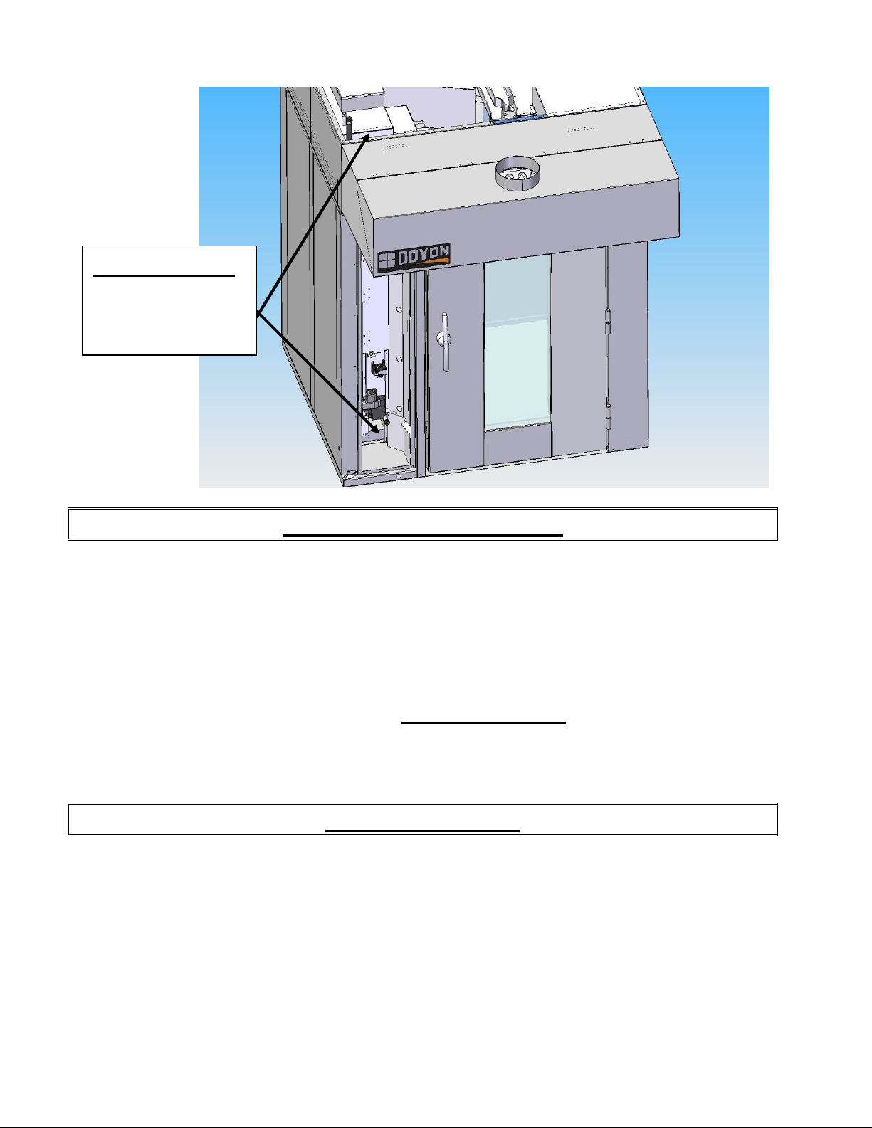
IMPORTANT
Burner Air Intake
Keep this area clean
and clear
A-4
DISTANCES TO RESPECT
For the installation near combustible materials
A) Back and sides of the oven: 0 inch.
B) Top of the oven: a clearance of 18 inches to the ceiling must exist to permit adequate venting
of the exhaust pipe and hot parts and to give a proper access to a technician.
C) Floor: The oven must be installed on a non-combustible floor.
D) you must have at least 18 inches when you evacuate through a hood canopy.
POWER FAILURE
No attempt should be made to operate the appliance during power failure.
The burner, the electric gas valve and the regulator are all designed to be failed safe. There is no
special action to take in case of electrical power failure.
If the main switch in ON when the power comes back, the oven will remain OFF and the oven
control will be energised. It is nevertheless recommended to turn OFF the main switch to protect the
electronic components.
FAM SROxG rev 07-13.doc 10/13
Page 8

A-5
AVERTISSEMENT LORS DE L'INSTALLATION
Les unités au gaz "DOYON" sont fabriquées pour être utilisées uniquement avec le type de gaz
spécifié sur la plaque d'identification. L’installation doit être conformes à la réglementation local,
ou en son absence, se référer au Code National de Gaz, ANSI-Z223.1-XX et CAN/CGA.B149.1-XX.
Référez-vous à l’année de la dernière édition pour XX. Des copies de ces normes sont disponibles
auprès de :
American Gas Association, 1515 Wilson Boulevard, Arlington, Virginia, 22209.
L'appareil et son robinet d'arrêt individuel doivent être débranchés du système d'alimentation en gaz
pendant tout test de pression du système à des pressions d'essai excèdent 1/2psi (3.5 kPa).
Pour votre commodité, cet appareil est conçu avec brûleur à allumage automatique direct. Suivez
les instructions de fonctionnement inclues dans ce manuel et affichées sur l'appareil.
Maintenez la zone appareil libre et exempte de matières combustibles. Ne pas obstruer le flux d'air
de combustion et la ventilation.
L'installation et le service doivent être faits par un technicien spécialisé. Contactez un technicien
spécialisé en gaz, en électricité et un plombier certifié pour l'installation.
Cet appareil doit être branché et mis à la terre (grounded) conformément aux règlements effectifs de
votre localité. Si aucune réglementation n'est établie, le four doit être branché conformément au Code
Canadien de l’électricité CSA 22.1-XX ou au Code National de l'Électricité NFPA 70-XX. Référez-vous
à l’année de la dernière édition pour XX. L’installation doit aussi permettre un accès suffisant pour
effectuer le service sur l’équipement (18 pouces au-dessus).
Le four doit être installé sous une ventilation adéquate :
Connection au-dessus hotte seulement : L’échappement des gaz de combustion se fait au travers de
Assurez-vous d'avoir un approvisionnement d'air suffisant afin d'assurer une ventilation adéquate pour
le bon fonctionnement du four.
Assurez-vous que les ajustements mentionnés dans la section "Installation" ont été faits
correctement avant d'allumer le four ou de le convertir à un autre type de gaz.
Association Canadienne du Gaz, 55 rue Scarsdale, Don Mills, Ontario, Canada, M3B 2R3.
INSTALLATION ET SERVICE
la hotte fourni. Un collet de diamètre 10 pouces à brancher sur système évacuation d’un minimum
900 cfm à dépression de 0.6 pouce colonne d’eau à la hotte. Le client doit fournir les conduits et le
ventilateur nécessaire selon le code local applicable. Un interrupteur à pression est installé sur
l’appareil et branché au système de sécurité du brûleur L’appareil est fourni un contact de relais de
max. 10.0 amp 1/2H.P. @ 120V pour l’opération du ventilateur. Consulter les autorités locales
pour déterminer si la hotte et les conduits de la hotte requis sont de Type I (graisse) ou Type II
(vapeur). La hotte peut-être connecté à un conduit d’évacuation de Type B, sauf si les produits
de cuisson évacuent de la graisse.
AVERTISSEMENT
FAM SROxG rev 07-13.doc 10/13
Page 9
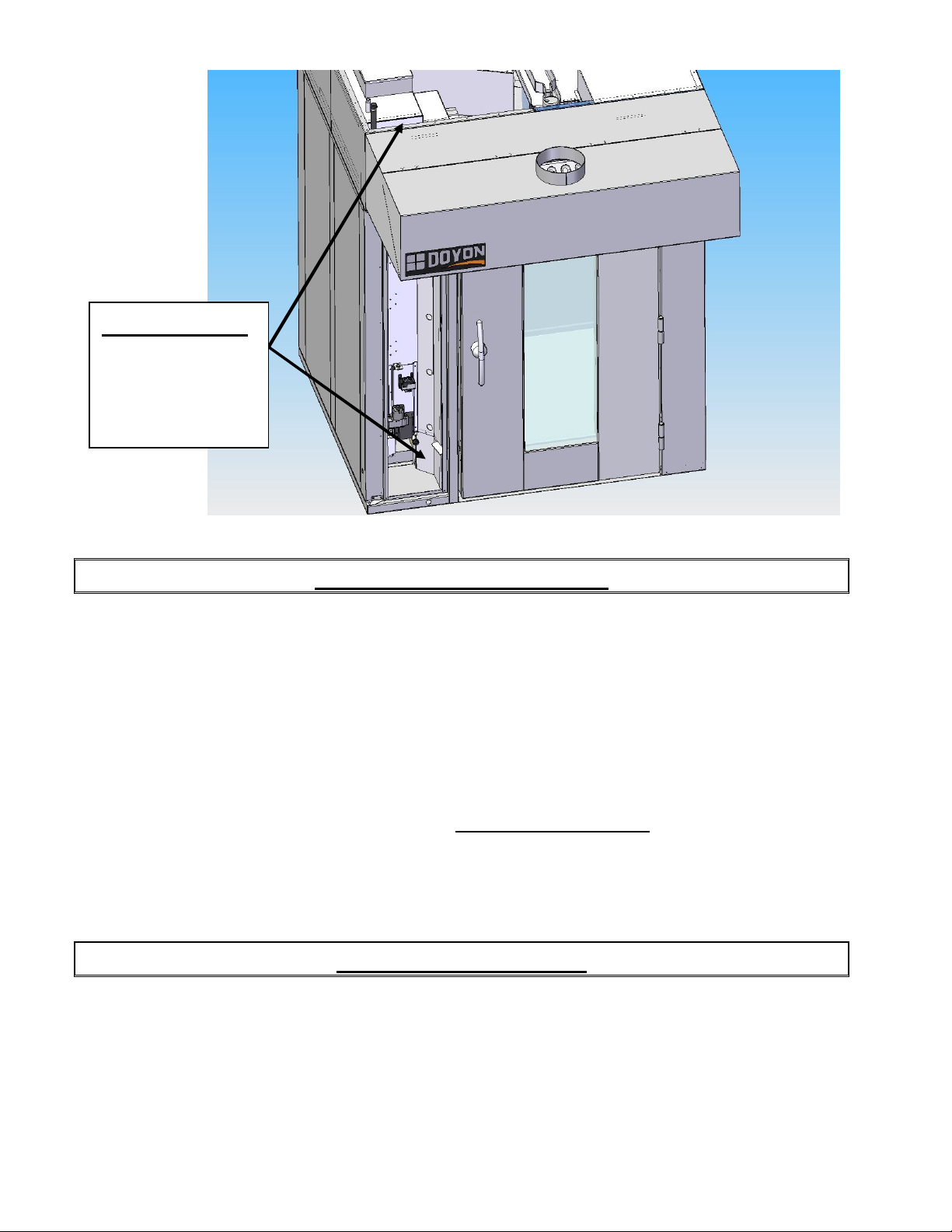
IMPORTANT
Entrée d’air du
brûleur.
Laisser cette région
libre et propre
A-6
DISTANCES À RESPECTER
Lors de l’installation près de matériaux combustibles
A) Arrière et côtés du four : 0 pouce.
B) Dessus du four : Il est obligatoire d'avoir au moins 18 pouces entre le dessus du four et le
plafond de manière à permettre une ventilation adéquat du tuyau
d’évacuation et des parties chauffantes tout en permettant l’accès à un
technicien.
C) Plancher : Le four doit être installé sur un plancher non combustible.
D) Il est recommandé d'installer une longueur supplémentaire de tuyau d'eau, de câble électrique
entre le four et le mur pour faciliter l'accès au technicien
PANNE DE COURANT
Pendant une panne de courant, on ne doit pas essayer d’opérer l’appareil.
Le brûleur et la valve à gaz automatique sont conçus de manière à être sécuritaires. La valve se
ferme en cas de panne électrique. Il n’y a donc aucune action spéciale à prendre de ce coté.
Lorsque le courant revient, le four demeurera arrêté et le contrôle sera sous tension si l’interrupteur
principal est en position MARCHE. Il est quand même recommandé de fermer l’interrupteur
principal du four pour protéger les composantes électroniques.
FAM SROxG rev 07-13.doc 10/13
Page 10

FAM SROxG rev 07-13.doc 10/13
Page 11
INPUT
REGULATOR
REGULATOR
INPUT
REGULATOR
REGULATOR
A-7
INSTALLATION
Take off the packaging material with care. Take off all the material used for packing and accessories.
Seal the unit on the floor with silicone. Verify every adjustments and correct it if necessary. Install
the hood covering the top front of the oven.
Each unit is set up to be used with the type of gas and electrical supply specified on the nameplate
fixed on the oven.
The installation must be conform with National fuel gas code ANSI Z223.1-XX and CAN/CGAB149-XX, Gas installation Code and local Codes where applicable. Refer to last edition year for
XX.
The oven's combustion system consists of a very safe gas burner certified in accordance to the
American Gas Association Standard in USA and with the Canadian Gas Association in Canada.
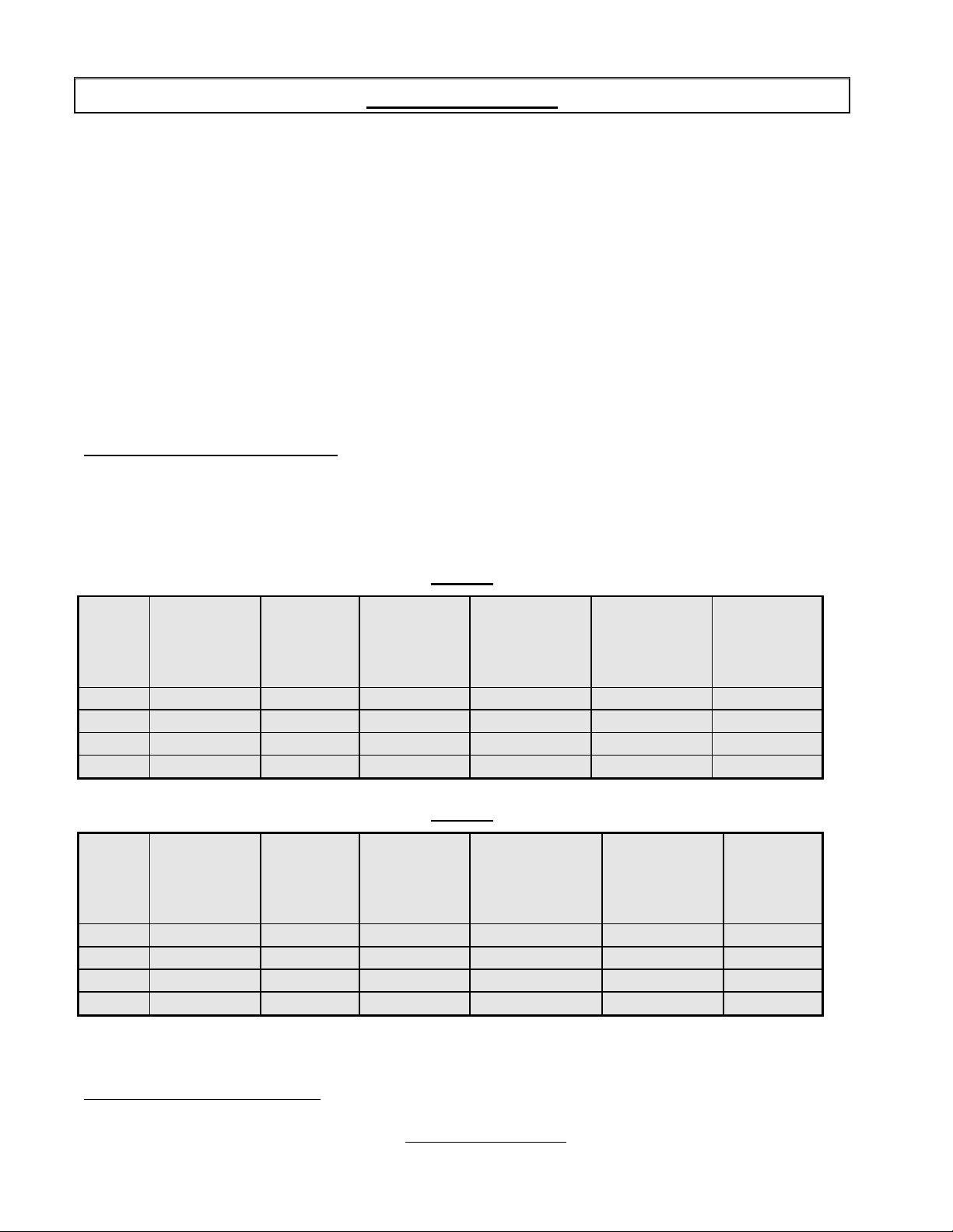
1. To the certified gas technician
The burner installed on DOYON gas fired ovens is set up and adjusted at the plant for a first class
operation. It is nevertheless necessary to verify on site the pressure at the burner input. The
following table indicates the pressures that must be set up to remain conform to the AGA standards
or CGA.
SRO1G
GAS
TYPE
Propane
MANIFOLD
PRESSURE
(Water column
inches)
ALTITUDE
(FT)
(BTU)
EACH
OVEN
SECTION
INPUT
PRESSURE
(Water column
inches)
OUTPUT
PRESSURE
(Water column
inches)
0-2000 175 000 11.0 8.6 8.5 # 66 drill
BURNER
ORIFICE
SIZE (DMS)
QTY=26)
Propane 2000-4500 175 000 11.0 8.6 8.5 # 66 drill
Natural
0-2000 175 000 7.0 3.4 3.3 # 53 drill
Natural 2000-4500 175 000 7.0 3.4 3.3 # 53 drill
SRO2G
GAS
TYPE
Propane
MANIFOLD
PRESSURE
(Water column
inches)
ALTITUDE
(FT)
(BTU)
EACH
OVEN
SECTION
INPUT
PRESSURE
(Water column
inches)
OUTPUT
PRESSURE
(Water column
inches)
0-2000 275,000 11.0 7.6 7.3 # 60 drill
BURNER
ORIFICE
SIZE (DMS)
QTY=26)
Propane 2000-4500 275,000 11.0 7.6 7.3 # 60 drill
Natural
0-2000 275,000 7.0 3.4 2.75 # 52 drill
Natural 2000-4500 275,000 7.0 3.4 2.75 # 52 drill
The burner used is adjusted for use with the gas indicated on the nameplate. It is nevertheless
possible to convert the burner to another gas by doing the modifications indicated in the
CONVERSION PROCEDURE provided with the oven. These modifications must be done carefully
and completely under the company's instruction to remain conform to A.G.A. or C.G.A standards.
Refer to Doyon Equipment to get the right CONVERSION KIT.
FAM SROxG rev 07-13.doc 10/13
Page 12

A-8
The pipe fittings compound must be certified for gas.
The customer must install a manual shut off valve at the end of the gas supply pipe near the
appliance which is approved by the American Gas Association Standard in the United States and
with the Canadian Gas Association in Canada.
Clean the air contained in the gas supply pipe at the installation to insure a successful firing on
the first try. The gas pipe sealing compound tightness must be verified using a solution of water
and soap prior to firing the unit.
WARNING
Make sure not to obstruct the overpressure opening on the gas regulator.
NOTE:If there's any modification done to the system or change of the type of gas used, make
sure that the regulator pressure of the burner is adjusted as recommended in this manual.
2. To the electrician
Electrical supply installation must be in accordance with the electrical rating on the nameplate.
A phase sequence and loss of phase relay is installed on 3 phases models to avoid wrong rotation
direction of the blowers. If the oven does not light up, swap two phases conductors in the supply
box and try again. Be sure that the power is really on the 3 phases wires next to the fuses in the
control compartment on the front of the oven. Check also if the control fuse located near the
main switch is not blown.
WARNING
The electrician must make sure that the supply cable does not come in contact with the oven top
which becomes hot.
3. To the plumber
This equipment is to be installed to comply with the applicable federal, state or local plumbing
codes.
Connect the water supply pipe to the oven using good quality sealing compound. Take care that
combustible water pipes do not come in contact with hot parts on the top of the oven.
Connect the steam system (1/2 NPT) to the cold water distribution network. Minimum Water
Flow required is 4.5 USGPM (0.29 l/sec).@ 50psi
We highly recommend a water softener to eliminate minerals in the water. We suggest you to use
Doyon installation kit number 50-1530 and replacement cartridges 50-1531 to achieve minimum
flow requirement.
FAM SROxG rev 07-13.doc 10/13
Page 13

A-9
INSTALLATION
Ouvrir avec soin l'emballage de votre équipement. Enlever tous les matériaux utilisés pour
l'envelopper ainsi que les accessoires... Appliquez un joint de silicone à la base de l’unité. Vérifiez
les ajustements et corrigez au besoin. Installez la hotte recouvrant le brûleur sur le devant du four.
Chaque unité est fabriquée pour être utilisée avec le type de gaz et la source électrique spécifiés sur
la plaque signalétique de l’appareil.
L'installation doit être conforme avec le Code National de Gaz, ANSI-Z223.1-XX et CAN/CGAB149-XX, le code d'installation au gaz et les codes locaux si applicables. Référez-vous à l’année de
la dernière édition pour XX.
Le système de combustion du four est conçu à partir d'un brûleur certifié en conformité avec les
normes de l'Association Américaine des Standards de Gaz et l'Association Canadienne de Gaz.
1. Au technicien spécialisé pour le gaz
Le brûleur installé sur les fours au gaz DOYON est monté et ajusté à l'usine par le fabricant pour un
fonctionnement optimal. Il est néanmoins nécessaire de vérifier sur place la pression à l'entrée du
brûleur. La table suivante indique la pression qui doit être ajustée pour se conformer aux standards
de AGA ou de CGA.
SRO1G
TYPE
DE GAZ
ALTITUDE
(PI)
ENTRÉE
(BTU)
PAR
SECTION
DE FOUR
PRESSION À
L’ENTRÉE DU
RÉGULATEUR
(Colonne d'eau en
pouces)
PRESSION À
LA SORTIE DU
RÉGULATEUR
(Colonne d'eau
en pouces)
PRESSION À
D'ADMISSION
AU BRÛLEURr
(Colonne d'eau
en pouces)
DIMENSION
ORIFICE
BRÛLEUR
Quantité =26
Propane 0-2000 175 000 11.0 8.6 8.5 Mèche #66
Propane 2000-4500 175 000 11.0 8.6 8.5 Mèche 66
Naturel 0-2000 175 000 7.0 3.4 3.3 Mèche #53
Naturel 2000-4500 175 000 7.0 3.4 3.3 Mèche #53
SRO2G
TYPE
DE GAZ
ALTITUDE
(PI)
ENTRÉE
(BTU)
PAR
SECTION
DE FOUR
PRESSION À
L’ENTRÉE DU
RÉGULATEUR
(Colonne d'eau en
pouces)
PRESSION À
LA SORTIE DU
RÉGULATEUR
(Colonne d'eau
en pouces)
PRESSION À
D'ADMISSION
AU BRÛLEURr
(Colonne d'eau
en pouces)
DIMENSION
ORIFICE
BRÛLEUR
Quantité =26
Propane 0-2000 275 000 11.0 7.6 7.3 Mèche #60
Propane 2000-4500 275 000 11.0 7.6 7.3 Mèche #60
Naturel 0-2000 275 000 7.0 3.4 2.75 Mèche #52
Naturel 2000-4500 275 000 7.0 3.4 2.75 Mèche #52
FAM SROxG rev 07-13.doc 10/13
Page 14

A10
Le brûleur utilisé est ajusté pour être installé seulement avec le type de gaz spécifié sur la plaque
d'identification. Il est néanmoins possible de convertir le brûleur à un autre type de gaz en
suivant les modifications mentionnées dans la PROCÉDURE DE CONVERSION fournis avec le
four. Pour demeurer conforme aux standards de AGA et CGA, ces modifications doivent être
faites au complet et avec précaution en suivant les instructions du manufacturier. Se référer à
Équipement Doyon pour obtenir le nécessaire de conversion adéquat.
Le composé de joint à tuyau utilisé pour relier les appareils au gaz doit être certifié résistant à
l'action du gaz.
Le client doit installer une vanne manuelle à la sortie de l'alimentation au gaz près de l’appareil,
laquelle doit être approuvée par l'Association Américaine des Standards de Gaz aux Etats-Unis
et par l'Association Canadienne de Gaz au Canada.
Pour vous assurer d'un bon allumage lors de votre premier essai, videz le tuyau d'alimentation
au gaz de l'air qu'il contient lors de l'installation. Les joints des tuyaux devraient être vérifiés
avec une solution d'eau et de savon pour détecter les fuites avant de faire fonctionner l'unité.
ATTENTION
Ne pas obstruer le limiteur de fuite du régulateur de pression.
NOTE:Dans le cas d'une modification du système ou d'un changement de type de gaz, s'assurer
d'ajuster la pression du régulateur du brûleur telle que recommandée dans ce manuel.
2. À l'électricien
L'installation de l'alimentation électrique des fours doit être conforme avec la source électrique
spécifiée sur la plaque signalétique.
AVERTISSEMENT
L'électricien doit s'assurer que le câble d'alimentation ne touche pas le dessus du four à cause
du degré élevé de chaleur dégagé par celui-ci.
3. Au plombier
Faire le raccordement d’entrée d’eau au four en utilisant des matériaux de qualité assurant
l’étanchéité. S’assurer que le tuyau d’arrivée d’eau n’est pas en contact avec les parties
chaudes sur le dessus du four.
Vérifier l’étanchéité de la valve électrique.
Relier le système de vapeur (1/2 NPT) au réseau de distribution d'eau froide.
Il est fortement recommandé d’installer un adoucisseur d’eau à l’entrée de l’appareil de
capacité minimum de 4.5 GPM (0.29 l/sec).@ 50psi afin d’éliminer les minéraux dans l’eau.
Nous recommandons l’ensemble d'installation Doyon modèle 50-1530 et la cartouche de
remplacement 50-1531 pour atteindre le débit d’eau requis par l’appareil.
FAM SROxG rev 07-13.doc 10/13
Page 15

A11
FAM SROxG rev 07-13.doc 10/13
Page 16

A-12
EBAKE PROGRAMMABLE CONTROL - OPERATING MODES
The Doyon Ebake controller has two operation modes Manual and Programmable.
MANUAL: to use all functions without using a recipe program.
PROGRAMMABLE : to use with a recipe program.
Program capacity
□ Program #1 is always used as the default Manual Cooking mode setting (single stage).
□ Programs #2 to #99 can have up to 8 stages each recipe.
OVEN START UP
Turn on the main power switch. The controller will power up and display:
□ OFF, PRESS POWER KEY TO START.
Press the red POWER key, the oven will go ON. The display will read PREHEAT and the oven will heat to reach the
MANUAL preset temperature. Then, the oven will display READY and the alarm will beep 5 times. This will mean that
the oven is at the desired temperature.
To turn the oven OFF, press the red POWER key and hold it for 3 seconds. The oven will run on COOL DOWN mode
until it reaches 250°F and then, it will automatically turn OFF. At this moment, the display will show : OFF, PRESS
POWER KEY TO START.
DOOR SWITCH
□ If the door is opened :
○ Display scrolls recipe NAME and DOOR OPEN.
○ All functions are turned OFF (unless in Cool Down mode, then the fan remains on).
○ All timers pause until the door is closed.
FAM SROxG rev 07-13.doc 10/13
Page 17

A-13
MANUAL MODE
This mode is used to work in a single stage.
Turn the dial until MANUAL is highlighted, press the dial to confirm
COOL DOWN FUNCTION
For fast cool down, press on the COOL DOWN key, the fan will remain ON while the door is open.
Note : if the oven reaches 200°F, it will turn OFF automatically. Display will show : OFF, PRESS POWER KEY TO
START.
TEMPERATURE FUNCTION
To change the temperature set point, press on . Display will show actual temperature set point. Turn the dial to select
.
the desired temperature set point (by increments of 5 degrees) and press
note that the new set point will automatically be saved after exiting if the dial is not pressed after changing the setting. If
the dial is not pressed or turned within 3 seconds, the last set temperature will be saved.
to confirm and exit the setting mode. Also,
TIMER FUNCTION
To change the time setting, press on
(by increments of 15 sec.) and press
the last set time will be saved.
Press on timer START/STOP key to start the timer countdown. At the end of the countdown, display will show BAKE
DONE. If needed, you can add 1 minute by pressing the ADD TIME key. It will automatically add 1 minute without
changing the original time setting. If more then one minutes is needed turn the dial to desired add time and press
When the countdown is finished, the display will show BAKE DONE.
Also, at any time during the countdown, the time can be paused by pressing on the TIMER START/STOP key or
cancelled by pressing and holding the START/STOP key for 3 seconds.
When the door is open, the timer pauses and the display indicates DOOR OPEN until the door is closed.
□ If the remaining time is less than 60 minutes, it will be displayed as MM:SS
□ If the remaining time is 60 minutes or more, it will be displayed as HH:MM
Note : Timer in MANUAL mode is only a reminder.
Display will show time setting. Turn the dial to select the desired timer setting
.
to confirm and exit setting. If the dial is not pressed or turned within 3 seconds,
FAN OFF DELAY FUNCTION
By pressing on the FAN OFF DELAY key, the fan remains OFF for a period of time before starting working in normal
fan mode. After pressing FAN OFF DELAY key, the display will show NONE. Turn the dial to select HIGH (3 minutes)
or LOW (2 minutes) fan off delay and press
OFF DELAY will be saved.
To cancel fan off delay, press the FAN OFF DELAY key, turn the dial to NONE and press
Note : during FAN OFF DELAY the oven heating system is not functional. A higher set point temperature preheat is
recommended if use more then 3 minutes FAN OFF DELAY.
If the dial is not pressed or turned within 3 seconds, the last set FAN
.
FAM SROxG rev 07-13.doc 10/13
Page 18

A-14
FAN SPEED
You can change the fan speed. There are 2 different fan speed setting available STD & HIGH available. Default speed is
STD. To select a different fan speed then STD press on the FAN SPEED key, turn the dial to desire fan speed and
press
This function will change the fan speed of the fan, creating a different air flow.
.
STEAM FUNCTION
Steam output can be turned ON only if oven temperature is >= (250°F /121°C).
○ Pressing SHOT STEAM key : A single steam injection will inject for duration of preset time. The
display will toggles the recipe name and the steam. following the steam injection you will have
automatically a FAN OFF DELAY for the period of steam after steam period, the vent system will
automatically evacuate steam out of the oven and go on normal baking cycle.
□ Note: When pressing the SHOT STEAM key, it will force the fan OFF.
○ Pressing PULSE STEAM key : It will create continuous steam injections. If pressed again, it will
cancel the pulse steam function. When active, the display scrolls recipe name and pulse steam.
□ Note: When pressing the PULSE STEAM key, the fan will stay ON to create continuous moisture during
the baking cycle.
VENT KEY FUNCTION
During Manual mode Only at any time vent can be open or close by pressing the vent key.
□ Note: When the SHOT STEAM sequence the vent will operate automatically.
RACK KEY FUNCTION
Rack is always rotated when oven is powered, when door are opening the rack will automatically index with the door
opening and drop down to load or unload the rack. If desired Rack can be stop and index during baking by pressing the
RACK key.
To restart the rack press again on the RACK key or after opening the door and closed back the rack will start rotating
in normal mode.
FAM SROxG rev 07-13.doc 10/13
Page 19

A-15
PROGRAMMED COOKING MODE
This mode is used to work with 1 to 8 stages recipe programs.
To select a programmed recipe, turn the dial until name or number of product is highlighted. Press
program. The oven will preheat to the programmed temperature. Display will show READY and the alarm will beep 5
times when the oven is at the desired temperature.
Press on START/STOP key to start the programmed recipe. The timer will countdown. At the end of the recipe, display
will show BAKE DONE. If needed, you can add time pressing the BAKE MORE TIME key. It will automatically add 1
minute without changing the original time setting. If more then one minutes is needed after pressing the BAKE MORE
TIME key, turn the dial to desire add time and press
DONE. Press on START/STOP key to stop the recipe.
Also, at any time during the countdown, the recipe can be paused by pressing on the START/STOP timer key or
canceled by pressing and holding the key for 3 seconds.
When the door is open, the timer pauses Rack will index and drop down to floor, the display shows DOOR OPEN until
the door is closed.
To see current stage information during baking process, press on the TIMER key. It will display recipe name, stage
number, stage status and time reminder.
Note : During a programmed recipe, the keys SHOT & PULSE STEAM, FAN OFF DELAY are not functional. All
those functions need to be set in the recipe program.
RACK FUNCTION
When the countdown is finished, the display will show BAKE
Rack is always rotated when oven is powered, when door are opening the rack will automatically
index with the door opening and drop down to load or unload the rack. If desired Rack can be stop
and index during baking by pressing the RACK key.
To restart the rack press again on the RACK key or after opening the door and closed back the rack
will start rotating in normal mode.
Cook Program Structure
Each recipe name can have maximum of 15 character. Up to 10 characters will show a fixe recipe name on the display. If
more then 10, the recipe name will scroll on the display and when timer is activate the recipe name will be fixe and show
only the 10 first characters.
Each recipe can have preheat temps, core probe, cook stage, cook & hold function. Each stage has the following
programmable parameters :
Time: the time duration of the current stage.
Oven temperature: the oven set point for current stage.
Steam: shot or pulse steam injected into the oven chamber.
Fan off delay: 0 to 3 minutes can be programmed after the shot steam injection.
Fan off delay: duration of the fan OFF
Fan speed: STD/HIGH
Vent opening: vent opening delay during stage.
Entering the Programming mode
to select product
Press the PROGRAM KEY . If the control is protected by a password. The display reads ENTER CODE. Use the
dial to enter the 4 digits code. Select the number and press to go to the next number. After the last number
confirmation, you will enter program mode.
FAM SROxG rev 07-13.doc 10/13
Page 20

A-16
Programming a product recipe
Note : the control can hold up to 99 recipes. Each recipe can have up to 8 stages.
Rotate the dial to the desired recipe and press .
To edit a new or existing name:
Turn the dial to the edit name or option name and press .
-EDIT NAME: Use dial to select each letter and press to step to the next letter.
-OPTION NAME: Select one of the library listed product name.
After product name is edited, you will enter to the following recipe programming mode.
1-PREHEAT
If no preheat needed: Use the dial to step on next programming function.
If preheat needed: Turn the dial to select preheat and press .Use the dial to select YES and press .
Rotate the dial to set the desire preheat temperature and press to exit and save preheat function.
2-STAGE PROGRAMMING
Turn the dial to the product stage 1 and press . Display will show the following programming process.
a) Set stage timer: Turn the dial to select desired current stage cooking time and press . Note if core probe is set to
cooking the cook time function will be disabled and you will start with set temperature instead of set Time.
b) Set temperature: Turn the dial to set the current stage temperature and press .
c) Steam: If no steam is needed, press to skip steam function and go to FAN speed.
If steam is needed, rotate the dial to select YES and press . Use the dial to select SHOT or PULSE and
press . If SHOT is selected, rotate the dial to select LOW(+/- 0.67 us gallon/ 2.6 liters) or HIGH(+/- 1
Usgallon/4 liters) steam and press .
If after steam SHOT fan delay is needed, set the fan off delay time (0 to 3min) and press . If no fan delay
needed set the time to 00:00.
To exhaust excess of steam after steam process, add desired time (0 to 3min) to activate and press . I f no
need set the time to 00:00
If pulse is selected, rotate the dial to select STD(steam every 2 minutes), HI(steam every 1 minute) or
MED(steam every 1.5 minutes) pulse and press .
d) Fan delay: If no fan delay is needed, press of the dial to skip to fan cycle. If fan delay is needed, rotate the dial to
select LOW (1 minutes) or HIGH (3 minutes) and press . If a fan off delay is needed, press to step to
fan cycle.
e) Fan Speed: If fan speed STD is ok, press . If HIGH fan speed, is desired, Turn the dial to select HIGH and press
.
f) Vent opening : If Vent need to be open during the stage set desired time you want the vent open, exp: if after 15 min
baking you want vent open set 15:00min, vent will open after 15 min for the balance of the stage time. normally
use to exhaust excess of product vapor before end of baking process or prevent excess of vapor coming out
during opening door.
You have now completed 1 stage program. If another stage is needed, select stage 2 and follow same process as stage 1.
If a 2nd stage is not needed, turn the dial to exit and the recipe will be registered.
FAM SROxG rev 07-13.doc 10/13
Page 21

A-17
MODE D'OPÉRATION DU CONTRÔLE PROGRAMMABLE
EBAKE
Le contrôle programmable Doyon EBAKE a deux fonctions d'opération Manuel et Programmable.
MANUEL: pour utiliser avec toutes les fonctions sans recette programmer.
PROGRAMMABLE : Pour utilisation avec recette programmée.
Capacité du Programme
□ Programmes 2 à 99 sont disponible avec 8 étapes par recette.
□ Programme #1 est toujours utilisé comme recette MANUEL par défaut, avec une seule étape.
DÉMARRAGE DU FOUR
Tournez l'interrupteur principal en position marche. Le contrôleur affichera
"ARRÊT APPUYER SUR DÉMARRER".
Appuyez sur la touche rouge DÉMARRER. Le four démarrera et l'affichage indiquera PRÉCHAUFFAGE. Le four
atteindra la température ajustée dans le mode MANUEL. Ensuite, le four affichera PRÊT, suivi d'une sonnerie de 5
coups, qui confirmera que le four est prêt à être utilisé.
Pour éteindre le four, appuyez et maintenir 3 secondes la touche DÉMARRER. Le four se mettra en mode
refroidissement jusqu’à ce que la température soit à 250°F et s'éteindra automatiquement. L'affichage indiquera :
ARRÊT APPUYER SUR DEMARRER
INTERRUPTEUR DE PORTE
□ Si la porte est ouverte :
○ L'affichage indiquera, en alternance, le nom de la recette et P OUVERTE.
○ Toutes les sorties seront en mode arrêt (sauf si la fonction refroidissement est activée, le ventilateur
demeurera en fonction).
○ Toutes les minuteries se mettront en mode pause jusqu’à ce que la porte se referme.
FAM SROxG rev 07-13.doc 10/13
Page 22

A-18
MODE MANUEL
Ce mode est utilisé pour travailler manuellement avec une étape de cuisson seulement.
À l'aide du sélecteur, mettre en surbrillance la recette MANUEL et appuyez sur
FONCTION REFROIDISSEMENT
Dans le cas où la température du four serait trop élevée et une température plus basse est désirée
rapidement, appuyez sur la
touche REFROIDISSEMENT . Le ventilateur restera en fonction lorsque la porte sera ouverte
afin d'abaisser la température du four rapidement.
Note : Lorsque la température atteindra 250°F, le four s'éteindra automatiquement. L'affichage indiquera : ARRÊT
APPUYER SUR DEMARRER
FONCTION TEMPERATURE
Pour changer la température, appuyez sur . L'affichage indiquera la température désirée. À l'aide du sélecteur,
.
ajustez la température désirée, (par incrément de 5 degrés) et appuyez sur
ajustement de la température.
Lorsque la température sera atteinte, l'affichage indiquera PRÊT, ouvrir les portes et enfourner les produits. Si la
minuterie est nécessaire, appuyez sur la touche DÉPART/ARRÊT de la minuterie. (voir instructions fonction minuterie)
pour confirmer et sortir du mode
FONCTION MINUTERIE
Pour changer le temps de la minuterie, appuyez sur
ajustez le temps désiré (par incrément de 15 secondes) et appuyez sur
du temps.
Appuyez sur la touche DÉPART/ARRÊT sous les touches minuteries, pour que la minuterie commence un compte à
rebours. À la fin du compte à rebours, si besoin, il est possible d'ajouter 1 minute en appuyant sur la touche AJOUT DE
TEMPS. Cela ajoutera automatiquement 1 minute à la minuterie sans changer l'ajustement original du programme.
Lorsque le temps est écoulé, l'affichage indiquera PRÊT À SORTIR. Appuyez sur DÉPART/ARRÊT pour annuler la
minuterie et la sonnerie.
Sortir les produits du four.
En tout temps, durant le compte à rebours de la minuterie, il est possible de mettre la minuterie en mode pause en
appuyant sur la touche DÉPART/ARRÊT ou de l’annuler en appuyant sur la touche DÉPART/ARRÊT de la minuterie
durant 3 secondes.
Lorsque les portes du four sont ouvertes, la minuterie se met en mode pause et l'affichage indique P. OUVERTE jusqu’à
ce que la porte soit refermer.
□ Si le temps indiqué est inférieur à 60 minutes, l'affichage indiquera le temps comme suit MM : SS
□ Si le temps indiqué est supérieur à 60 minutes, l'affichage indiquera le temps comme suit HH : MM
Note : La minuterie en mode MANUEL est une fonction de rappel seulement, elle ne contrôle pas la cuisson.
Pour contrôler la cuisson avec la minuterie, vous devez programmer une recette.
L'affichage indiquera le temps désiré. À l'aide du sélecteur,
.
pour confirmer et sortir du mode ajustement
FAM SROxG rev 07-13.doc 10/13
Page 23

A-19
FONCTION DÉLAI DU VENTILATEUR
En appuyant sur la touche DELAI DU VENTILATEUR, le ventilateur peut se mettre en mode arrêt pour un temps
prédéterminé avant de démarrer en mode normal. Après avoir appuyé sur la touche DELAI DU VENTILATEUR,
l'affichage indiquera AUCUN. À l'aide du sélecteur, sélectionnez le temps de délai du ventilateur désiré HAUT 3
minutes ou BASSE 2 minutes et appuyez sur
Pour annuler, appuyez sur la touche DÉLAI DU VENTILATEUR sélectionnez AUCUN à l'aide du sélecteur et appuyez
sur
pour confirmer ou maintenez enfoncer la touche DÉLAI DU VENTILATEUR pour 3 secondes.
pour confirmer.
FONCTION VITESSE VENTILATEUR
En appuyant sur la touche VITESSE DU VENTILATEUR La vitesse du ventilateur peut être changé. Deux (2) vitesse
de ventilation STD ou HAUTE
FONCTION GÉNÉRATION DE VAPEUR
La vapeur peut être activée seulement si la température interne du four est supérieure à 250°F /121°C.
La vapeur peut être activée seulement lorsque le ventilateur est en fonction.
○ VAPEUR PULSÉE : Active la vapeur par cycle pulsé afin d'avoir une humidité constante durant une
cuisson. Pour annuler la fonction, appuyez à nouveau sur la touche . Lorsque la vapeur pulsée est
activée, l'affichage indique en alternance le nom de la recette en cours et vapeur pulsée et le ventilateur est
toujours en marche.
○ VAPEUR UNIQUE : La vapeur s'active en début de cuisson pour un temps prédéterminer.
□ Note: La vapeur unique en mode manuel, va forcer le ventilateur en mode arrêt. Lorsque cette fonction est
active, l'affichage indiquera en alternance le nom de la recette en cours et vapeur. Après l'injection de la
vapeur un délais du ventilateur prédéterminer est en fonction, suite au délais le système d'évent va s'ouvrir
pour un temps prédéterminer afin d'évacuer le surplus de vapeur dans la chambre de cuisson. Lorsque les 3
étapes mentionner seront terminer, le ventilateur va ce mettre en marche.
FONCTION CHARIOT
Cette fonction est disponible seulement avec les fours munis du chariot rotatif. Elle permet de mettre en mode arrêt
le chariot durant la cuisson. En appuyant sur la touche , le chariot va s'indexer à la position arrêt, pour annuler le
mode arrêt du chariot, appuyez de nouveau sur la touche ou ouvrir et refermer la porte du four.
FAM SROxG rev 07-13.doc 10/13
Page 24

A-20
MODE DE CUISSON PROGRAMMÉ
Ce mode est utilisé pour travailler avec 1 à 8 étapes pour chaque programme de recette.
À l'aide du sélecteur, choisir une recette pour qu’elle soit en surbrillance et appuyez sur
four va préchauffer à la température programmée de la recette sélectionnée. Lorsque que le programme sera prêt à
démarrer, l'affichage indiquera PRÊT et une sonnerie se laissera entendre à 5 reprises.
Ouvrir les portes et enfourner les produits.
Appuyez sur DÉPART/ARRÊT pour commencer le cycle de cuisson. Le temps est compté à rebours. À la fin du
programme, l'affichage indiquera PRÊT À SORTIR. Vous pourrez ajouter du temps de cuisson, si besoin, en appuyant
sur la touche AJOUT DE TEMPS. Cela ajoutera automatiquement 1 minute supplémentaire sans changer le programme
original. Lorsque terminé, l'affichage indiquera de nouveau PRÊT À SORTIR, appuyez sur DÉPART/ARRÊT et sortir
les produits du four.
À n'importe quel temps durant le programme, il est possible de mettre le programme en mode pause en appuyant sur
DÉPART/ARRÊT ou de l’annuler en appuyant et en maintenant 3 secondes la touche DÉPART/ARRÊT.
Lorsque les portes sont ouvertes le programme se mettra en mode pause et l'affichage indiquera P. OUVERTE jusqu’à la
fermeture des portes.
Pour voir l'état du programme en cours, appuyez sur la touche MINUTERIE. L'affichage indiquera le nom de la recette,
le numéro de l'étape en cours et le temps restant.
Note : Pendant un programme de cuisson, les touches suivantes ne sont pas active, elles doivent être programmées dans
la recette. VAPEUR UNIQUE, VAPEUR PULSÉE, VITESSE DU VENTILATEUR, DÉLAI DU VENTILATEUR.
pour la sélectionner. Le
FAM SROxG rev 07-13.doc 10/13
Page 25

A-21
Structure de programmation
Chaque nom de recette peut contenir 10 caractères. Chaque recette peut avoir : une température de préchauffage,
fonction sonde à viande, mode cuire et attendre. Chaque étape de programme a les paramètres suivants programmables :
Temps: Le temps de l'étape en cours.
Température du four : La température de chaque étape en cours.
Vapeur : Injection de la vapeur UNIQUE ou PULSÉE dans le four au début de la cuisson ou durant l'étape
en cours. Aussi, au besoin, un temps de pause du ventilateur après l'injection de la vapeur unique peut être
programmer.
Délai du ventilateur.
Vitesse du ventilateur
Ouverture Évent
Access au mode programmation de recette
Appuyez sur la touche PROGRAMME . Si le contrôleur est protégé par un mot de passe, l'affichage indiquera
ENTRER CODE. Utilisez le sélecteur pour entrer le code à 4 chiffres. Appuyez sur pour chaque chiffre choisi afin
de passer au suivant. Après le dernier numéro, confirmez. Vous allez entrer dans le mode programme recette. Si le code
n'est pas valide, vous allez sortir du mode programme recette.
Pour une nouvelle recette:
À l'aide du sélecteur, choisir une recette disponible . Appuyez sur pour y avoir accès.
Pour éditer une nouvelle recette ou une existante:
À l'aide du sélecteur, choisir éditer le nom ou nom optionnel et appuyez sur .
-EDITER NOM: À l'aide du sélecteur, choisir la lettre désirée et appuyez sur pour passer à la lettre suivante.
-OPTION NOM: À l'aide du sélecteur, sélectionnez un nom préenregistré à la liste de noms de produits.
Après que le nom est éditer, vous allez entré dans le mode programmation suivant.
Programmer un recette
Note: Le contrôleur EBAKE peut contenir un maximum de 99 recettes. Chaque recette peut utiliser 8 différentes étapes
de cuisson.
Après que le nom du produit soit édité, à l'aide du sélecteur, mettre en surbrillance le nom du produit et appuyez sur
pour choisir le produit.
1-PRÉCHAUFFAGE :
Si préchauffage n'est pas nécessaire: Tourner le sélecteur pour aller a la fonction suivante.
Si la recette nécessite un préchauffage à l'aide du sélecteur, choisir préchauffage et appuyez sur . À l'aide du
sélecteur choisir OUI et appuyez sur . À l'aide du sélecteur, ajustez la température de préchauffage désirée et
appuyer sur pour sortir et sauvegarder la fonction préchauffage.
2-Programmation d'une étape: À l'aide du sélecteur, mettre le nom de la recette étape 1 en surbrillance et appuyez sur
pour le sélectionner l'étape.
-Temps de cuisson: À l'aide du sélecteur, ajustez le temps de cuisson de l'étape en cours et appuyez sur .
-Ajuster la température: À l'aide du sélecteur, ajustez la température désirée de l'étape en cours et appuyez sur .
FAM SROxG rev 07-13.doc 10/13
Page 26

A-22
Vapeur: Si non utilisée, appuyez sur pour sauter la fonction vapeur et passer a l'étape vitesse du ventilateur.
Si la vapeur est utilisée, à l'aide du sélecteur, sélectionnez OUI et appuyez sur . Ensuite, à l’aide du
sélecteur, choisir UNIQUE ou PULSE et appuyez sur . Si UNIQUE est sélectionné, à l'aide du sélecteur,
choisir la vapeur BASSE (+/-2.6 Litres) ou HAUTE (+/- 4 Litres) et appuyez sur . Si un délai du ventilateur
est nécessaire, à l'aide du sélecteur, ajustez un temps de délai du ventilateur, ajustable entre 00:00 et 3 minutes
Si nécessaire affin de sortir l’excès de vapeur après son procéder, a laide du sélecteur ajuster le temps désirer de
l'ouverture de l'évent après le délai de ventilateur.
(0 signifie pas d,évent délai ou ouverture évent après l'injection de la vapeur unique) et appuyez sur .
Si la vapeur PULSE est sélectionnée, à l'aide du sélecteur choisir STD (défaut au 2 minutes), MED(au 1.5
minutes) ou HAUTE ( au 1 minute) et appuyez sur .
-Délai du ventilateur: dans le cas ou la vapeur n'est pas utiliser il est possible de programmer la fonction suivante.
Si un délai du ventilateur n'est pas nécessaire appuyez sur pour passer à la fonction suivante : cycle du ventilateur.
Si un délai du ventilateur est nécessaire, à l'aide du sélecteur, choisir le délai du ventilateur désiré BASSE (2 minutes) ou
HAUTE (3 minutes) et appuyez sur pour passer à la fonction suivante.
-Vitesse de ventilateur: Si activée, la vitesse par défaut est STD. Appuyez sur . Si la HAUTE vitesse est nécessaire,
à l'aide du sélecteur choisir HAUTE et appuyez sur .
-Ouverture de l'évent: si a la fin ou durant une étape l'ouverture de l'évent est nécessaire pour évacuer l’excès de vapeur
causer par le produit, programmer le temps que l'évent devras ouvrire exp.: si après 15 minute de cuisson vous désirer
ouvrir l'évent pour le reste de l'étape ajuster le temps a 15 min.
normalement utiliser pour évacuer les vapeur provenant du produit avant la fin de la cuisson ou pour éviter l’excès de
vapeur qui sort lors de l'ouverture de la porte.
Vous avez maintenant terminer une programmation complète d'un stage. Si un autre stage est nécessaire, à l'aide du
sélecteur choisir l'étape 2 et répéter les instructions ci haut. Si une autre étape n'est pas nécessaire, à l'aide du sélecteur,
mettre en sur brillance SORTIR et appuyez sur pour sortir et sauvegarder la recette.
Appuyez sur la touche pour retourner en mode normal de cuisson.
FAM SROxG rev 07-13.doc 10/13
Page 27

The oven temperature drops when loading
This is normal. The opening of the door produces an important loss
The oven does not turn on.
Check the breakers
of the building.
The oven does not produce heat.
Make sure the thermostat is adjusted to a temp
erature high
A-23
TROUBLESHOOTING
WARNING: Always disconnect the power supply to the appliance before cleaning, doing preventive maintenance or
servicing.
WARNING: Contact the factory, the factory representative or a local service company to perform maintenance and
repair.
Convection blower, draft inducer motor, vent motor and rack lift/rotating system are on the top of the oven. These
components are sealed and don’t require lubrication.
Electric Control parts, gas manual shut off valve, water manual shut off valve are behind the control panel door.
BEFORE CALLING FOR SERVICE ANSWERS TO MOST FREQUENT QUESTIONS
Questions Solutions
and needs a certain amount of time before it
stabilizes.
of heat. The rack loaded with cold pastries need a large amount of
heat to get back to its original temperature. The same thing
happens with domestic ovens. You will realize that your new SRO
oven can provide an excellent baking quality for any kind of
products you want to bake.
Check the breaker on the front panel.
Check if the door is tightly closed.
Inside the control compartment, check if the breaker of the
convection blower is ON
enough to turn on the heat.
Check that the gas manual shut-off valve is open
1. If the Hood Vent Blower is not on
Check its power supply.
2. If the oven blower is not on
Check the breaker behind the control door.
3. Check burner draft inducer if work and draft inducer damper if
open.
4. If the control display gas system fault press on the dial to
reset system and restart oven.
5. Check the LED blinking sequence on the ignition module.
Steady ON : replace module
1 blink: Air flow pressures switches issue, refer to point 1 & 3.
2 blink: flame ON without heat demand shut off gas valve call
gas technician.
3 blink: module Lockout shut off oven power for 10 second to
reset.
If it does not start up again, contact our company or a certified gas
technician.
FAM SROxG rev 07-13.doc 10/13
Page 28

The burner goes to lock
-
out because
of:
The burner is equipped with multiple interlocked safety devices.
Uneven baking.
Verify that hot air diffuser and convection air intake is not block.
If steam device of the oven does not work
Check if the water supply valve (of the building) is open.
a) Flame failure:
b) The spark is irregular or not present:
c) The air pressure switch does not close its
contact.
properly.
In the event of a failure of the flame or any blockage of the
combustion air supply or exhaust, the burner will "lock out" in
the safety condition.
Air has not been bled from the gas line.
Porcelain insulators cracked (very little crack is enough).
Spark probe grounded.
It may be disconnected, incorrectly set or defective or maybe
the blower is not running.
Do not use foil on the grills.
Verify the temperature of the oven by using an oven thermometer
and make sure that it is even with the thermostat setting.
Verify if water manual shut off valve located behind the control
panel is open.
Steam injection is not permitted if actual oven temperature is
below 250F
The oven must be idling at temperature over 350F for at least 15
minutes to get a good amount of steam
Verify if “Y” filter is clean (First, turn the water manual shut off
valve OFF and bleed the line by having the appliance
injecting water.)
Check the solenoid valve.
FAM SROxG rev 07-13.doc 10/13
Page 29

C’est normal. L'ouverture de la porte fait entrer une grande
Vérifier le disjoncteur du p
anneau avant du four.
DÉPANNAGE
AVERTISSEMENT : Toujours couper l’alimentation de l’appareil avant de faire le nettoyage, le
maintien ou la réparation
AVERTISSEMENT : Contacter le fabricant, son représentant ou un technicien de service local pour
effectuer la maintenance ou la réparation de cet équipement.
Le moteur de convection, le ventilateur d’échappement, les moteurs de volet et les composantes du
système de lever/rotation du chariot sont accessibles par le dessus du four.
Les composantes de contrôle électrique, la valve à gaz manuelle, la valve à eau manuelle sont
derrière la porte du contrôle
AVANT D'APPELER LE DÉPARTEMENT DE SERVICE
SOLUTION AUX PROBLÈMES LES PLUS FRÉQUENTS
Problèmes Solutions
La température du four baisse lors de
l'enfournage et prend un certain temps avant
de se stabiliser.
Le four ne démarre pas.
Le four ne produit pas de chaleur.
quantité d'air froid dans le four. Le chariot chargé de pâtisseries
froides nécessite une quantité considérable de chaleur avant que le
four ne se stabilise à la température préréglée. Le même
phénomène se produit dans les fours domestiques. Vous
constaterez la très haute qualité de cuisson réalisée avec votre
four SRO pour les divers types de pâtisseries
Vérifier les disjoncteurs du bâtiment.
Vérifier si la porte est bien fermée.
Vérifier le disjoncteur du moteur de convection à l’intérieur du
compartiment de contrôle.
Assurez-vous que le thermostat est ajusté à une température
suffisamment élevée.
Vérifier si la vanne à gaz manuelle est ouverte.
1. Si la ventilation de la hotte ne marche pas:
Vérifier son disjoncteur du coté du bâtiment.
Si le contrôle affiche ERREUR SYTÈME GAZ, appuyer sur le bouton
rotatif pour enclencher le système et redémarrer le four.
Vérifier la séquence de flashage du DEL sur le module
d’allumage du brûleur.
a) Allumer : Remplacer le module.
b) 1 flashe : Interrupteur de pression ouvert, vérifier la ventilation de
la hotte et ou du moteur d’évacuation des brûleurs.
c)2 flashe : Présence de flamme sans demande de chauffage,
fermer la valve a gaz et contacter un technicien.
d)3 flashe : Le module est en faute, fermer l’appareil pour 30
secondes et le re démarrer si le problème persiste contacter
un technicien.
Si le brûleur ne s'allume toujours pas, appeler notre
compagnie ou contacter un technicien en gaz.
FAM SROxG rev 07-13.doc 10/13
Page 30

brûleur est conçu avec de multiples fonctions de
a une anomalie, le brûleur se
Il peut être débranché, désajusté, défectueux ou le
que les entrées et les sorties d’air de
nvection ne sont pas bloquées. Ne recouvrez pas
température actuelle du four est en dessous de
50F pour
si la valve à eau principale du four et à
(Avant de
manuelle et purger cette section en demandant une
Le brûleur bloque à la position de
sécurité parce que :
a) La flamme s'éteint:
b) L'ignition est irrégulière ou il n'y
en a aucune :
c) L'interrupteur de pression d'air ne
ferme pas ses contacts.
Cuisson inégale.
Le
sécurité. S'il y
bloquera à la position de sécurité.
Il reste de l'air dans le tuyau de gaz.
L'isolant de porcelaine est fissurée.
L’électrode d’allumage est mise à la terre.
ventilateur ne fonctionne pas.
Vérifier
co
les grilles de papier d'aluminium.
Le four ne produit pas de vapeur.
L’injection de vapeur n’est pas permise si la
250F. Assurez-vous que le four cycle à 3
une période de 15 minutes avant d’injecter la
vapeur.
Vérifiez
l’intérieur du compartiment de contrôle sont bien
ouvertes.
Vérifiez si le filtre à eau en « Y » est propre.
démonter le bouchon, fermer la valve à eau
injection de vapeur au contrôle.
Vérifiez si la valve électrique fonctionne.
Gardez l'entrée d'air du brûleur libre de toute obstruction.
AVERTISSEMENT
Ne jamais essayer de modifier les contrôles du brûleur.
Toute modification requiert les services d'un technicien qualifié ainsi que les instructions du fabricant.
FAM SROxG rev 07-13.doc 10/13
Page 31

mend to use Stainless steel oven
316 Silicone base protector and lubricant for
A-27
OVEN MAINTENANCE AND CLEANING
WARNING: Always disconnect the power supply to the appliance before cleaning,
doing preventive maintenance or servicing.
Questions Solutions
Clean the inside of the oven proofer with
water and soap.
After cleaning the inside of the oven, apply a
We recom
cleaner
We recommend and sell:
silicone base oven protector. It avoids food
from sticking to the metal.
oven
Dow Corning
Part number : EXS400
Clean the oven windows with products like
Brasso or equivalents. They are copper
cleaners but good for this use
We recommend and sell:
Wright's: Cream copper cleaner
J.A. Wright & Co.
Part number : EXC300
Clean the oven exterior with a stainless steel
cleaner.
We recommend and sell:
Stainless steel cleaner
SANY or CURTIS (comestible)
Part number : NES201
MAINTENANCE OF THE BURNER
Every three months verify and clean the burner air inlet in order to remove dust and
1. Clean the air inlet of the control and burner compartment
2. The in-shot burner.
3. Inspect and clean both burners electrodes
4. Verify the burner input and output pressure.
5. Verify proper operation of flue gas damper and draft inducer.
6. Verify Steam Generator bars, distribution pan and drain pan for scale build up. If needed, let
them soak in a descaler solution or vinegar. Then rinse prior to installation.
particles. (Refer to page A-4)
Once a year, you should ask a certified technician to make a tune up.
Make sure everything works properly, verify and clean especially:
FAM SROxG rev 07-13.doc 10/13
Page 32

Produit recommandé: nettoyeur concu pour acier
A-28
ENTRETIEN ET NETTOYAGE DU FOUR
AVERTISSEMENT : Toujours couper l’alimentation de l’appareil avant de faire le
nettoyage, le maintien ou la réparation
Étape par étape Solutions
Nettoyer l'intérieur du four avec de l'eau et un
détergent.
Après avoir nettoyé l'intérieur du four,
appliquer un protecteur sur les parois et les
grilles. Le produit empêche les aliments de
coller sur les parois du four.
Nettoyer les vitres du four avec du Brasso ou un
produit équivalent. Bien que ce soit des
nettoyeurs à cuivre, ils s'avèrent très efficaces.
Nettoyer l'extérieur du four avec un produit
d'entretien pour l'acier inoxydable.
inoxidable pour interieur de four.
Produit recommandé:
Protecteur de silicone pour four
No de pièce: EXS400
Produit recommandé:
Nettoyeur pour vitres de four
No de pièce: EXC300
Produit recommandé:
Nettoyeur pour acier inoxydable
No de pièce: NES201
ENTRETIEN DU BRÛLEUR
Aux trois mois, vérifier et nettoyer l’entrée d’air du compartiment électrique et celle du
brûleur pour enlever toute accumulation de poussière ou de mousse. (Voir page A-6).
Vous devriez faire faire l’entretien de votre système de brûleur par un technicien
qualifié une fois par année. Le technicien doit s’assurer que tout fonctionne bien, vérifier
et nettoyer spécialement :
1. L’entrée du compartiment électrique et celle du brûleur.
2. Nettoyer si nécessaire les mélangeurs de chaque brûleur.
3. Inspecter et nettoyer les 2 électrodes du brûleur.
4. Vérifier la pression d’entrée et sortie de la valve à gaz.
5. Vérifier l’opération du ventilateur de la cheminée du brûleur et de son volet. Nettoyer si
nécessaires.
6. Vérifier s’il y a des dépôt de calcaire dans le générateur de vapeur : les bars, le plat de
distribution d’eau et le récipient de drain. Au besoin, nettoyer avec un détartrant ou du
vinaigre. Bien rincer avant de remettre en place les composantes
FAM SROxG rev 07-13.doc 10/13
Page 33

A29
A-39
NOTES
FAM SROxG rev 07-13.doc 10/13
Page 34

LIMITED WARRANTY
(Continental United States Of America And Canada Only)
Doyon Equipment Inc. guarantees to the original purchaser only that its product are
free of defects in material and workmanship, under normal use.
This warranty does not cover any light bulbs, thermostat calibration or defects due to
or resulting from handling, abuse, misuse, nor shall it extend to any unit from which
the serial number has been removed or altered, or modifications made by
unauthorised service personnel or damage by flood, fire or other acts of God. Nor will
this warranty apply as regards to the immersion element damaged by hard water.
The extent of the manufacturer’s obligation under this warranty shall be limited to the
replacement or repair of defective parts within the warranty period. The decision of
the acceptance of the warranty will be made by Doyon Equipment service
department, which decision will be final.
The purchaser is responsible for having the equipment properly installed, operated
under normal conditions with proper supervision and to perform periodic preventive
maintenance.
If any parts are proven defective during the period of one year from date of purchase,
Doyon Equipment Inc. hereby guarantees to replace, without charge, F.O.B. Linière,
Quebec, Canada, such part or parts.
Doyon Equipment Inc will pay the reasonable labour charges in connection with the
replacement parts occurring within one year from purchase date. Travel over 50
miles, holiday or overtime charges are not covered. After one year from purchase
date, all labour and transportation charges in connection with replacement parts will
be the purchaser’s responsibility.
Doyon Equipment Inc. does hereby exclude and shall not be liable to purchaser for
any consequential or incidental damages including, but not limited to, damages to
property, damages for loss of use, loss of time, loss of profits or income, resulting
from any breach or warranty.
In no case, shall this warranty apply outside Canada and continental United States
unless the purchaser has a written agreement from Doyon Equipment Inc.
Page 35

GARANTIE LIMITÉE
(Pour le Canada et les États continentaux des États-Unis)
Équipement Doyon Inc. garantit ses produits à l'acheteur original, contre tout défaut
de matériaux ou de fabrication, en autant qu'ils aient été utilisés de façon normale.
Cette garantie ne s'applique cependant pas sur les ampoules, les calibrations de
température, tout défaut dû ou résultant d'une mauvaise manipulation, d'un emploi
abusif ou d'un mauvais usage. La garantie ne s'applique pas non plus sur tout
équipement dont le numéro de série aurait été enlevé ou altéré, tout produit modifié
par du personnel de service non autorisé, endommagé par une inondation, un feu ou
tout autre acte de Dieu, ni sur les éléments immergés endommagés par l'eau dure.
L'étendue des obligations du manufacturier, selon cette garantie, est le remplacement
ou la réparation des pièces défectueuses durant la période de garantie. L'acceptation
de la garantie sera faite par le département de service d'Équipement Doyon Inc.
Cette décision sera définitive.
L'acheteur est responsable de faire installer son équipement adéquatement, de
l'opérer sous des conditions normales d'utilisation avec une bonne supervision, ainsi
que d'effectuer un entretien préventif périodique.
Dans le cas où les pièces s'avéreraient défectueuses durant une période d'un an à
partir de la date d'achat, Équipement Doyon Inc. s'engage à les remplacer, sans
frais, F.O.B. Linière, Québec, Canada.
Équipement Doyon Inc. couvrira les frais raisonnables de main-d'œuvre reliés au
remplacement des pièces, pour une période d'un an à partir de la date d'achat.
Toutefois, les frais encourus pour les déplacements au-delà de 50 milles, le temps
supplémentaire et les jours de congé ne sont pas couverts. Au-delà d'un an après la
date d'achat, tous frais de transport et de main-d'œuvre pour le remplacement des
pièces sont la responsabilité de l'acheteur.
Équipement Doyon Inc. ne se tient pas responsable envers l'acheteur pour toutes
conséquences ou dommages incluant, mais non limités à, dommages à la propriété,
dommages pour perte d'usage, perte de temps, perte de profits ou de revenus,
provenant de tout bris de garantie.
En aucun cas, cette garantie ne s'applique à l'extérieur du continent des États-Unis
d'Amérique ou du Canada, à moins que l'acheteur n'ait une entente écrite avec
Équipement Doyon Inc.
FAM SROxG rev 07-13.doc 10/13
 Loading...