

Page 1
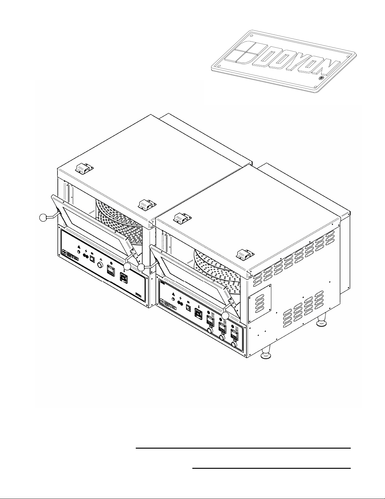
FPR2 & FPR3
Product / Produit:
Serial number / Numéro de série:
Page 2

Page 3

IMPORTANT SAFETY INSTRUCTIONS
SAVE THESE INSTRUCTIONS
DANGER
TO REDUCE THE RISK OF FIRE OR ELECTRIC SHOCK
CAREFULLY FOLLOW THESE INSTRUCTIONS
TABLE OF CONTENTS
(table des matières :page suivante)
Description ___________________________________________________________________ A-1
Introduction________________________________________________________________ A-2
Construction _______________________________________________________________ A-2
Shipping __________________________________________________________________ A-2
Installation warnings_________________________________________________________ A-4
Distances to respect__________________________________________________________ A-4
Installation ________________________________________________________________ A-6
Operation of the oven ________________________________________________________ A-8
Instructions for oven ________________________________________________________ A-10
Troubleshooting ___________________________________________________________ A-12
Oven maintenance and cleaning _______________________________________________ A-14
How to cook your favorite pizza_______________________________________________ A-16
Bake chart ________________________________________________________________ A-20
Stacking kit instruction ______________________________________________________ A-22
Component parts ________________________________________________________________B-1
FPR2 Front view_____________________________________________________________B-2
FPR2 Interior front ___________________________________________________________B-4
FPR2 Side & back____________________________________________________________B-6
FPR3 Front view_____________________________________________________________B-8
FPR3 Interior front __________________________________________________________B-10
FPR2/FPR3 Element_________________________________________________________B-12
FPR2-2 / FPR3-2____________________________________________________________B-14
Control Panels__________________________________________________________________C-1
FPR2 & FPR3 1PH 208-240V 50/60HZ ___________________________________________C-2
Warranty ________________________________________________________________________1
FPR [LIVRET].doc Rev. 04/2010
Page 4

IMPORTANT INSTRUCTIONS DE SÉCURITÉ
CONSERVEZ CE MANUEL D’INSTRUCTIONS
DANGER
AFIN DE RÉDUIRE LES RISQUES D'INCENDIE OU D'ÉLECTROCUTION
SUIVRE CES INSTRUCTIONS AVEC SOIN
TABLE DES MATIÈRES
Description ____________________________________________________________________A-1
Introduction ________________________________________________________________A-3
Construction ________________________________________________________________A-3
Expédition __________________________________________________________________A-3
Avertissement lors de l'installation_______________________________________________A-5
Distances à respecter _________________________________________________________A-5
Installation _________________________________________________________________A-7
Opération du four ____________________________________________________________A-9
Instructions pour four ________________________________________________________A-11
Dépannage ________________________________________________________________A-13
Entretien et nettoyage du four__________________________________________________A-15
Comment faire cuire facilement de la pizza _______________________________________A-18
Tableau de cuisson __________________________________________________________A-21
Instruction pour installation superposée _________________________________________A-22
Pièces composantes _____________________________________________________________B-1
FPR2 Vue de face ____________________________________________________________B-2
FPR2 Devant intérieur ________________________________________________________B-4
FPR2 Côté & arrière _________________________________________________________B-6
FPR3 Vue de face ____________________________________________________________B-8
FPR3 Devant intérieur _______________________________________________________B-10
FPR2/FPR3 Elément_________________________________________________________B-12
FPR2-2 / FPR3-2 ___________________________________________________________B-14
Panneaux de contrôle ____________________________________________________________C-1
FPR2 & FPR3 1PH 208-240V 50/60HZ ___________________________________________C-2
Garantie ________________________________________________________________________1
FPR [LIVRET].doc Rev. 04/2010
Page 5

SECTION A:
DESCRIPTION / DESCRIPTION
Page 6

A-2
INTRODUCTION
The manufacturer suggests to read this manual carefully.
This equipment is manufactured with first quality material by experienced technicians. Proper
installation and maintenance will guarantee a reliable service for years to come.
A nameplate fixed to the front or right side of the oven specifies the model number, serial number,
voltage and amperage.
Drawings and replacement parts numbers are included in this manual. The electrical diagram is affixed
in the control panel at the back of the oven.
ATTENTION
DOYON is not responsible for damages to the property or the equipment caused
by personnel who is not certified by known organisations. The customer is
responsible for finding qualified technicians in electricity and plumbing for the
installation of the oven.
CONSTRUCTION
You just bought the most advanced oven in the world, "DOYON" technology at it’s best. This oven is
manufactured using the highest quality components and material.
The oven gives a perfect uniform baking with its unique Jet Air convection system. The DOYON oven
is designed with parts that are easy to find.
SHIPPING
For your safety, this equipment has been verified by qualified technicians and carefully crated before
shipment. The freight company assumes full responsibility concerning the delivery in good condition of
the equipment in accepting to transport it.
IMPORTANT
RECEPTION OF THE MERCHANDISE
Take care to verify that the received equipment is not damaged before signing the delivery receipt. If a
damage or a lost part is noticed, write it clearly on the receipt. If it is noticed after the carrier has left,
contact immediately the freight company in order that they do their inspection.
We do not assume the responsibility for damages or losses that may occur during transportation.
Page 7

A-3
INTRODUCTION
Le fabricant suggère de lire attentivement ce manuel et de suivre avec soin les instructions fournies.
Votre équipement est fabriqué avec des matériaux de première qualité par des techniciens
d'expérience. Une utilisation normale et un entretien adéquat de l'équipement vous assureront
plusieurs années de bon service.
Une plaque signalétique, située sur le coin avant droit ou le côté droit du four, mentionne le numéro
de modèle, le numéro de série, la tension et l'ampérage.
Les dessins et les numéros de pièces de rechange sont inclus dans ce manuel. Le plan électrique est
affiché dans la boîte de contrôle à l'arrière du four.
ATTENTION
Équipement Doyon Inc. ne peut être tenu responsable pour les dommages causés à
la propriété ou à l'équipement par du personnel non certifié par des organismes
accrédités. Le client a la responsabilité de retenir les services d'un technicien
spécialisé en électricité et d'un plombier qualifié pour l'installation du four.
CONSTRUCTION
Vous avez maintenant en votre possession le four le plus performant présentement disponible sur le
marché, un four utilisant la technologie "DOYON" à son meilleur. Ce four est fabriqué avec des
matériaux de première qualité.
Avec son système unique de convection «Jet Air», ce four vous permettra d'obtenir une cuisson
uniforme. Le four Doyon est fabriqué avec des matériaux et pièces composantes facilement disponibles
sur le marché.
EXPÉDITION
Pour votre protection, cet équipement a été vérifié et emballé avec précaution par des techniciens
qualifiés avant son expédition. La compagnie de transport assume la pleine responsabilité
concernant la livraison de cet équipement en bon état en acceptant de le transporter.
IMPORTANT
RÉCEPTION DE LA MARCHANDISE
Avant de signer le reçu de livraison, prenez soin de vérifier dès la réception si l'équipement n'est pas
endommagé. Si un dommage ou une perte est détecté, écrivez-le clairement sur le reçu de livraison
ou votre bon de transport et faites signer le livreur. Si le dommage est remarqué après le départ du
transporteur, contactez immédiatement la compagnie de transport afin de leur permettre de
constater les dommages causés.
Nous ne pouvons assumer la responsabilité pour les dommages ou les pertes qui pourraient survenir
pendant le transport.
Page 8

A-4
INSTALLATION WARNINGS
POWER FAILURE WARNING
WHEN YOU HAVE A POWER FAILURE, SHUT OFF THE OVEN POWER SWITCH TO
PROTECT THE ELECTRONIC COMPONENTS WHEN THE POWER COMES BACK.
FOR YOUR SAFETY
DO NOT STORE OR USE GASOLINE OR OTHER FLAMMABLE VAPORS
AND LIQUIDS IN THE VICINITY OF THIS OR ANY APPLIANCE.
INSTALLATION AND SERVICE
WARNING
IMPROPER INSTALLATION, ADJUSTMENT, ALTERATION, SERVICE OR
MAINTENANCE CAN CAUSE PROPERTY DAMAGE, INJURY OR DEATH.
READ THE INSTALLATION, OPERATING AND MAINTENANCE INSTRUCTIONS
THOROUGHLY BEFORE INSTALLING OR SERVICING THIS EQUIPMENT.
Installation and service must be done by specialised technicians. Contact a certified electrician and
plumber for set up.
The oven must be connected to the utility and electrically grounded in conformity to the effective
local regulations. If these are not established, the oven must be connected according to the Canadian
Electrical Code (CSA-C22.1-XX) or National Electrical Code (NFPA 70-XX). Refer to last edition
year for XX. Installation must also allow proper access for service (24 inches each side and back).
The ovens must be installed with a proper ventilation according with the local building code.
DISTANCES TO RESPECT
A) Back and sides of the oven: 4 pouces.
B) Top of the oven: a clearance of 12 inches to the ceiling must exist to permit adequate
venting of the exhaust pipe and hot parts and to give proper access to a
technician. The draft hood must have a clearance of 2 inches minimum all
around.
C) Floor: on it's legs 4 inches minimum.
D) Sides of the oven: do not install other than easily removable equipment for service and
maintenance (not closer than 4 inches).
E) It is recommended to have a certain length of electric cable between oven and wall to help
gain access for service.
Page 9

A-5
AVERTISSEMENT LORS DE L'INSTALLATION
PANNE ÉLECTRIQUE
LORS D'UNE PANNE ÉLECTRIQUE, FERMER L'INTERRUPTEUR DU FOUR POUR
PROTÉGER LES COMPOSANTES ÉLECTRONIQUES.
POUR VOTRE SÉCURITÉ
NE PAS EMMAGASINER OU UTILISER D'ESSENCE OU AUTRES VAPEURS
ET LIQUIDES INFLAMMABLES À PROXIMITÉ DE CET ÉQUIPEMENT
OU DE TOUT AUTRE APPAREIL.
INSTALLATION ET SERVICE
AVERTISSEMENT
UNE INSTALLATION, UN AJUSTEMENT, UNE ALTÉRATION, UN SERVICE OU UN
ENTRETIEN NON CONFORME AUX NORMES PEUT CAUSER DES DOMMAGES À LA
PROPRIÉTÉ, DES BLESSURES OU LA MORT. LIRE ATTENTIVEMENT LES DIRECTIVES
D'INSTALLATION, D'OPÉRATION ET D'ENTRETIEN AVANT DE FAIRE
L'INSTALLATION OU L'ENTRETIEN DE L'ÉQUIPEMENT.
L'installation et le service doivent être faits par un technicien spécialisé. Contactez un technicien
spécialisé en électricité.
Cet appareil doit être branché et mis à la terre (grounded) conformément aux règlements effectifs de
votre localité. Si aucune réglementation n'est établie, le four doit être branché conformément au Code
Canadien de l’électricité CSA 22.1-XX ou au Code National de l'Électricité NFPA 70-XX. Référez-vous
à l’année de la dernière édition pour XX. L'installation doit aussi permettre un accès suffisant pour
effectuer le service sur l'équipement (24 pouces sur toutes les faces).
Le four doit être installé sous une ventilation adéquate respectant les norme locales.
DISTANCES À RESPECTER
A) Arrière du four : 4 pouces.
B) Dessus du four : Il est obligatoire d'avoir au moins 12 pouces entre le dessus du four et le
plafond de manière à permettre une ventilation adéquate du tuyau
d’évacuation et des parties chauffantes tout en permettant l’accès à un
technicien.
C) Plancher : Une distance de 4 pouces minimum.
D) Les côtés du four : Installer uniquement des équipements légers et faciles à déplacer pour être
en mesure d'effectuer l'entretien de l'appareil (4 pouces minimum).
E) Il est recommandé d'installer une longueur supplémentaire de câble électrique entre le four et le
mur pour faciliter l'accès au technicien.
Page 10

A-6
INSTALLATION
IN GENERAL
Take off the packaging material with care. Take off all the material used for packing and accessories.
If the equipment is delivered with casters, always lock the wheels after installation and use flexible
wire. It must also be installed with restraining device (chain comes with the oven) to guard against
transmission of strain to the gas supply and connectors.
1. To the electrician
Electrical supply installation must be in accordance with the electrical rating on the nameplate.
WARNING
The electrician must make sure that the supply cable does not come in contact
with the oven top which becomes hot.
Page 11

A-7
INSTALLATION
EN GÉNÉRAL
Ouvrir avec soin l'emballage de votre équipement. Enlever tous les matériaux utilisés pour
l'envelopper ainsi que les accessoires.
Si l'appareil est muni de roulettes, veuillez toujours les bloquer après l'installation et utiliser un
cordon souple. De plus, des équipements de retenues (chaîne comprise avec le four) doivent être
installés pour empêcher le tuyau d'alimentation et les connecteurs de subir des tensions lorsque le
four est déplacé.
1. À l'électricien
L'installation de l'alimentation électrique des fours doit être conforme avec la source électrique
spécifiée sur la plaque signalétique de l’appareil.
AVERTISSEMENT
L'électricien doit s'assurer que le câble d'alimentation ne touche pas le dessus du
four à cause du degré élevé de chaleur dégagée par celui-ci.
Page 12

A-8
OPERATION OF THE OVEN
1. Turn the switch to the " ON " position.
• The light inside the oven must light up.
2. Adjust the thermostat at the desired setting (see THERMOSTAT INSTRUCTIONS below).
N.B. The red light must be "ON" (If not, press the breaker on the front).
3. Heat the unit until you reach the baking temperature.
When the desired temperature is reached, the red light goes out and turns green.
If the light is still "ON" and the oven does not produce heat, call for service.
4. Load the oven as fast as possible to avoid letting out too much heat.
5. Set the timer to the desired value and start it. (See page A-10.)
NOTE: The timer does not shut the oven off at the end of its cycle. It simply activates the
buzzer.
6. Wait until the product is ready. Do not open the doors until the product is done.
VERY IMPORTANT
This oven has an overheat warning alarm to protect the electrical components against overheating. If
the red pilot light (OVERHEAT WARNING) is lit and you hear a buzzer, see Troubleshooting.
THERMOSTAT INSTRUCTIONS
To obtain a very good thermal stability, we use a digital temperature controller with thermocouple.
The Omron E5CS thermostat controls the heat of every element at the SP (set point).
The temperature of the oven is always shown on the display of the thermostat and an arrow indicates
if the temperature is over or below the SP. When the green light is lit, it indicates that the
temperature is at the SP ± 1 %.
To adjust the SP (set point) value, you just have to press the key on the left and use the up and down
keys to set the temperature. Press the left key to return to run mode.
Page 13

A-9
OPÉRATION DU FOUR
1. Démarrer le four (tourner le sélecteur à la position "MARCHE").
•
La lumière à l'intérieur du four doit allumer.
2. Ajuster le thermostat à la température désirée (voir FONCTIONNEMENT DU THERMOSTAT).
N.B. L'affichage digital doit être allumé. Si ce n'est pas le cas, vérifier le disjoncteur situé
sur le panneau avant.
3. Laisser chauffer jusqu'à ce que la température de cuisson soit stable, une lumière verte située
sur le thermostat s'allumera pour l'indiquer. (Si l'afficheur du thermostat est allumé et que le
four ne produit pas de chaleur, il y a un problème, contacter une compagnie de service.)
4. Enfourner le four le plus rapidement possible afin d'éviter de faire sortir la chaleur du four.
5. Ajuster et démarrer la minuterie (voir les explications à la page A-11).
NOTE: À la fin du cycle, la minuterie n'arrête pas le four de chauffer. Elle ne fait qu'émettre
un avertissement sonore.
6. Attendre que les produits soient complètement cuits avant d'ouvrir les portes.
TRÈS IMPORTANT
Ce four est équipé d’une alarme de surchauffe afin d’éviter des bris de pièces causés par la chaleur
dans les contrôles avant. Si la lampe témoin avis de surchauffe à côté du thermostat est allumée et
qu’une sonnerie se fait entendre; référez-vous à la section Dépannage.
FONCTIONNEMENT DU THERMOSTAT
Afin d'obtenir une très bonne stabilité thermique, nous utilisons un contrôleur de température digital
associé à un thermocouple. Le thermostat Omron E5CS maintient la température au point de
réglage SP (set point).
En tout temps, le contrôleur de température affiche la température du four et une flèche indique si
elle est supérieure ou inférieure au point de réglage SP (set point). Une lumière verte indique que la
température est à ± 1% de la valeur SP.
Pour régler la température, il suffit de presser sur le bouton de gauche pour sélectionner la variable
(SP) et d'utiliser les flèches pour régler la valeur. Il faut ensuite revenir au mode de fonctionnement
normal en appuyant à nouveau sur le bouton de gauche.
Page 14
A-10
INSTRUCTIONS FOR OVEN
COOKING TIMER
Set the baking time required with the small push button on the timer. The yellow display is the
setting time and the red display is the countdown time (Ex: 25 minutes = set 2500 on green display).
After setting: Push the START/STOP button then, when the time is expired, the buzzer will rings.
Push the START/STOP button again to stop the buzzer.
If you want to restart the time in the middle of the countdown, press on the yellow RST button on the
timer.
P.S.The timer is simply a reminder for the approximate duration of the baking time.
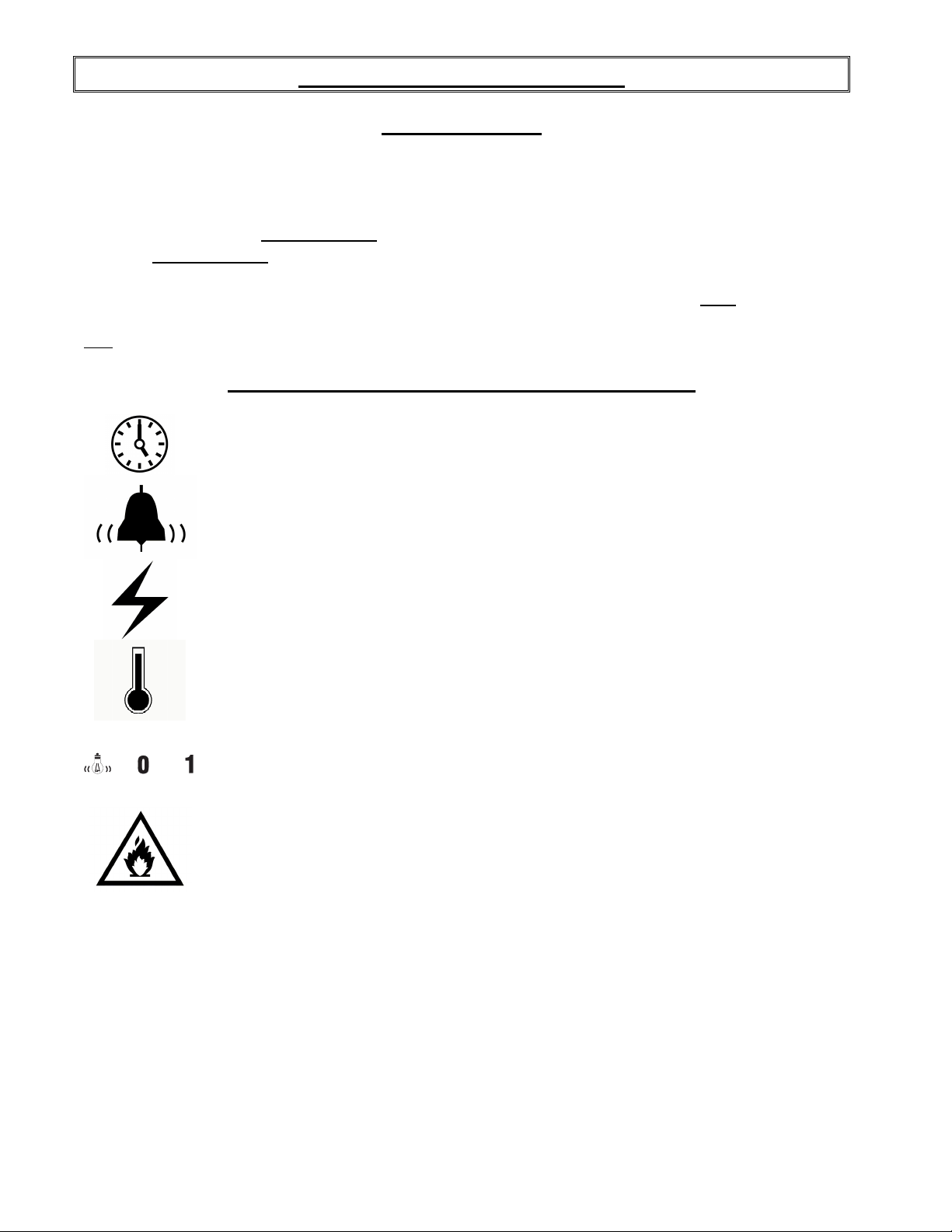
FRONT CONTROL PANEL SYMBOL SIGNIFICATION
Cooking timer
On / Off cooking timer switch
Breaker
Temperature control
OFF/ON main power switch
Overheat alarm
Page 15
A-11
INSTRUCTIONS POUR FOUR
MINUTERIE DE CUISSON
Le mécanisme doit être ajusté au temps désiré (utiliser les boutons en bas de l’affichage).
L'affichage vert est le temps désiré et l'affichage rouge est le décompte du temps de cuisson avant
que la sonnerie ne se fasse entendre.
Exemple: 25 minutes = 2500 (sur la minuterie)
Après ajustement: Presser le bouton poussoir MARCHE / ARRÊT. Quand le temps sera expiré, la
sonnerie de la minuterie retentira. Presser le bouton poussoir MARCHE / ARRÊT à nouveau pour
l’arrêter.
Si vous désirez repartir le décompte à nouveau avant que celui-ci soit terminé, appuyer sur le
bouton RST jaune sur la minuterie et le temps va repartir de nouveau automatiquement.
NB : La minuterie est tout simplement une aide (guide) pour la durée approximative de cuisson. Elle
ne provoque pas l’arrêt du four.
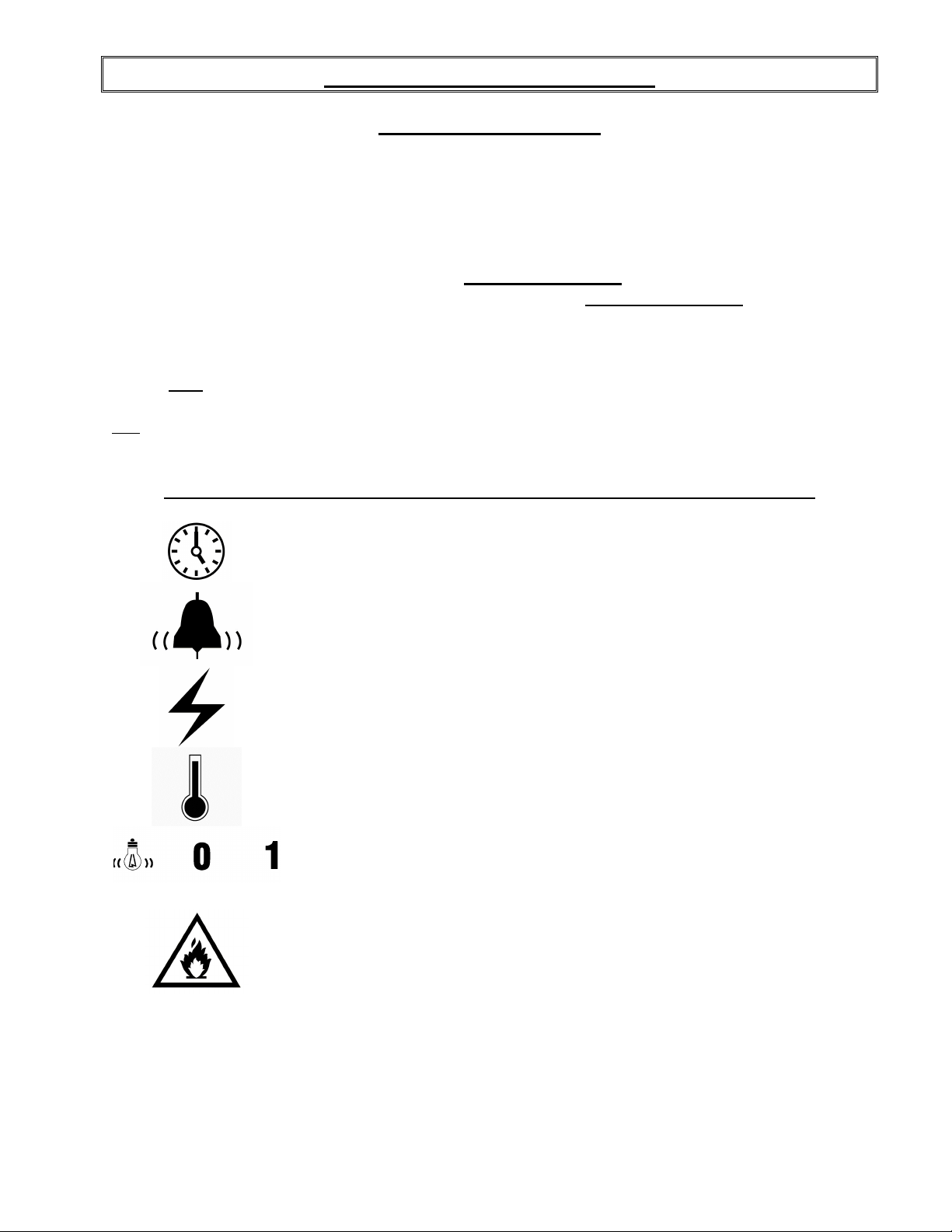
SIGNIFICATION DES SYMBOLES SUR LE PANNEAU DE CONTRÔLE AVANT
Minuterie de cuisson
Bouton de marche / arrêt de la minuterie de cuisson
Disjoncteur
Contrôle de température
MARCHE/ARRÊT principal de l'appareil
Avis de surchauffe des composantes électriques
Page 16

A-12
TROUBLESHOOTING
BEFORE CALLING FOR SERVICE
ANSWERS TO MOST FREQUENT QUESTIONS
Always cut off the main power before replacing any parts. Take care of the electric wire
supply system when pulling the oven.
Control parts on the front control:
Motor system on the back of the oven:
Questions Solutions
The oven does not turn on.
Uneven baking.
The oven does not produce heat.
Remove the side panels of the oven and the
proofer by screwing out the screws.
Pull the oven and screw out the panels.
Check the breakers on the front panel.
Check the breakers of the building.
Check if the doors are tightly closed.
Make sure that the grills don.t obstruct the air
flow. Do not use foil on the grills.
Verify if the rack inside the oven rotates.
Verify the temperature of the oven by using an
oven thermometer and make sure that it is even
with the thermostat setting.
1. If the oven blowers are on
• Make sure: the thermostat is adjusted to a
temperature high enough to turn on the pilot
light.
If the OVERHEAT WARNING light is on,
and you hear the warning buzzer.
2. If the oven blowers are not on
• Check the overload relays located in the
control compartment. If anyone of these is
disengaged, call for a qualified technician.
Check if the cooling fan airflow is not obstructed.
Check the cooling fan if it is running. If the
malfunction light goes on, or if the audible
sound, appliance is malfunctioning.
TURN OFF or disconnect appliance from power
supply and have serviced by a electrician.
Page 17

DÉPANNAGE
AVANT D'APPELER LE DÉPARTEMENT DE SERVICE
SOLUTION AUX PROBLÈMES LES PLUS FRÉQUENTS
Toujours fermer l'approvisionnement du courant principal avant le remplacement de pièces.
A-13
Les pièces de contrôle du four:
Système de moteur à l'arrière du four:
Problèmes Solutions
Le four ne démarre pas.
Le four ne produit pas de chaleur.
Cuisson inégale.
Enlever le panneau de contrôle avant (dévisser les
vis du panneau et le basculer lentement vers l'avant).
Déplacer le four vers l'avant et dévisser le panneau
arrière.
Vérifier les disjoncteurs du panneau avant du
four.
Vérifier les disjoncteurs du bâtiment.
Vérifier si les portes sont bien fermées.
1. Si les moteurs tournent:
•
Assurez-vous que le thermostat est ajusté à
une température suffisamment élevée pour
faire allumer la lampe témoin.
2. Si les moteurs ne tournent pas:
•
Vérifier les relais de surcharge situés dans la
boîte de contrôle. Si un des relais n'est pas
engagé, appeler un technicien qualifié.
Assurez-vous que les grilles permettent à l'air de
circuler librement. Ne recouvrez pas les grilles
de papier d'aluminium.
La lampe témoin AVIS DE SURCHAUFFE est
allumée et une sonnerie se fait entendre
Vérifiez la température du four à l'aide d’un
thermomètre à four et comparez avec le réglage
du thermostat.
Vérifier si le conduit de la ventilation du
ventilateur de refroidissement n'est pas obstrué.
Vérifier si le ventilateur fonctionne. Si le témoin
rouge s'allume, ou un signal sonore se fait
entendre, FERMER l'interrupteur ou débrancher
l'appareil et appeler un électricien.
Page 18

A-14
OVEN MAINTENANCE AND CLEANING
Questions Solutions
Clean the inside of the oven and the proofer
with water and soap.
Take out the grills (the grills of the oven could
be cleaned with "Easy-Off").
After cleaning the inside of the oven, apply a
silicone base oven protector. It avoids food
from sticking to the metal.
Clean the oven windows with products like
Brasso or equivalents. They are copper
cleaners but good for this use
Clean the oven exterior with a stainless steel
cleaner.
We recommend and sell:
Dirt Buster III: Action foam cleaner
CHEMCO
Part number: NEB201
We recommend and sell:
316 Silicone base protector and lubricant for
oven
Dow Corning
Part number : EXS400
We recommend and sell:
Wright's: Cream copper cleaner
J.A. Wright & Co.
Part number : EXC300
We recommend and sell:
Stainless steel cleaner
SANY or CURTIS (comestible)
Part number : NES201
Page 19

ENTRETIEN ET NETTOYAGE DU FOUR
Étape par étape Solutions
A-15
Nettoyer l'intérieur du four et de l'étuve avec de
l'eau et un détergent.
Enlever les grilles.
(Les grilles du four peuvent être nettoyées avec
du "Easy-Off".)
Après avoir nettoyé l'intérieur du four,
appliquer un protecteur sur les parois et les
grilles. Le produit empêche les aliments de
coller sur les parois du four.
Nettoyer les vitres du four avec du Brasso ou un
produit équivalent. Bien que ce soit des
nettoyeurs à cuivre, ils s'avèrent très efficaces.
Nettoyer l'extérieur du four avec un produit
d'entretien pour l'acier inoxydable.
Produit recommandé:
Dirt Buster III
Nettoyant à four à action moussante
No de pièce: NEB201
Produit recommandé:
Protecteur de silicone pour four
No de pièce: EXS400
Produit recommandé:
Nettoyeur pour vitres de four
No de pièce: EXC300
Produit recommandé:
Nettoyeur pour acier inoxydable
No de pièce: NES201
Page 20

A-16
HOW TO COOK YOUR FAVORITE PIZZA
(Pan pizza or regular)
How to cook pan pizza in ovens:
Models: FPR2 ans FPR3
1. Mix your favorite pizza dough formula.
2. When mixing is done:
A. Cut dough in pieces and make balls.
B. Put the dough balls in a plastic basket with a cover.
C. Place in a cooler or refrigerated room for 12 hours.
D. After 12 hours:
1) Remove dough balls from cooler or refrigerated room.
2) Spray the pizza pan with vegetable oil or olive oil.
3) Shape and set pizza dough in the pan.
4) Transfer pizza pan to proofer unit for 45 to 60 minutes.
Proofer set at: 100°F heat, 85% humidity.
5) When pizza dough is ready, put pizza pan with the cover on, back in the cooler.
6) When ready to bake:
• Take the pizza dough from the cooler;
• Put topping on pizza dough;
• Place the pizza in the oven without cover.
Important: If you cook your pizza in a pan or on a screen, the bottom crust will not bake
properly. If you use them, remove the pizza from the pan or the screen after 3
minutes and finish baking it directly on the oven deck.
Oven baking instructions:
• Preheat at 465ºF.
• Baking time:
5-6 mins: 6" 9" 12"
6-8 mins: 16" 18"
Page 21

How to cook regular pizza:
(No pan or screen)
• Preheat oven at 465ºF.
• Remove dough balls from cooler one hour before using.
• For better results:
Dough must be 50ºF to 80ºF.
Bake directly on perforated nickel plate.
Baking time at 465ºF:
5-6 mins: 6" 9" 12"
6-7 mins: 16" 18"
Important: Do not cook with screens.
Cook directly on the perforated nickel deck of the oven.
A-17
Cleaning:
We recommend to clean the oven every day.
1) Remove the lower shelf and clean the bottom of the oven with dry cloth and cleaner supplied
with the oven.
2) Glass doors: During working hours, clean glass with dry cloth (paper towel). At the end of the
day, clean with glass cleaner (Windex and paper towel).
NOTICE:
Never put aluminum foil on top of the shelves. This will affect the air circulation and the oven will
not bake properly.
Page 22

A-18
COMMENT FAIRE CUIRE FACILEMENT DE LA PIZZA
(Pan pizza ou pizza régulière)
Comment cuire la pan pizza dans votre four:
Modèles de four: FPR2 et FPR3
1. Préparer votre pâte à pizza à partir de votre recette favorite.
2. Une fois que la pâte est mélangée:
A. Couper la pâte en petits morceaux et la façonner sous forme de boules.
B. Mettre les boules de pâte dans un bac de plastique avec un couvercle.
C. Placer dans un réfrigérateur ou une chambre réfrigérée pendant 12 à 24 heures.
D. Après 12 à 24 heures:
1) Retirer les boules de pâte du réfrigérateur ou de la chambre réfrigérée.
2 Vaporiser le moule (pan) d'huile végétale ou d'huile d'olive.
3) Façonner et placer la pâte dans le moule.
4) Transférer le moule dans l'étuve pour 45 à 60 minutes.minutes.
Régler l'étuve à : 100°F (37°C) de chaleur, 85% d'humidité.
5) Lorsque la pâte à pizza est prête, replacer le moule, avec un couvercle dessus, dans le
réfrigérateur ou la chambre réfrigérée.
6) Pour la cuisson:
•
Retirer la pâte à pizza du réfrigérateur ou de la chambre réfrigérée;
•
Ajouter les ingrédients sur la pâte à pizza;
•
Placer la pizza dans le four (sans le couvercle).
Important: Afin d’obtenir une meilleur cuisson avec l’utilisation de moule ou de plaque
perforée, enlevez la pizza du moule ou de la plaque après 3 minutes de cuisson et
terminez la cuisson avec la pizza directement sur la plaque du four.
Instructions pour la cuisson au four :
•
Préchauffer le four à 465°F(240°C).
•
Temps de cuisson:
5-6 mins: 6" 9" 12"
6-8 mins: 16" 18"
Page 23

Comment cuire la pizza «régulière»:
(Sans moule ni plaque perforée)
•
Préchauffer le four à 465°F(240°C).
•
Retirer les boules de pâte du réfrigérateur ou de la chambre réfrigérée une heure avant la
cuisson.
•
Pour de meilleurs résultats:
La pâte doit être à une température entre 50°F(5°C) et 80°F(25°C)
Temps de cuisson à 465°F(240°C):
5-6 mins: 6" 9" 12"
6-8 mins: 16" 18"
Important:Ne pas cuire avec des plaques perforées.
Cuire directement sur la plaque de nickel perforée du four.
A-19
Nettoyage:
Nous vous recommandons de nettoyer votre four tous les jours.
1) Enlever la tablette du bas. Nettoyer le fond du four avec un essuie-tout et le produit nettoyant
fourni avec le four.
2) Vitre des portes : Durant les heures de travail, nettoyer la vitre régulièrement avec un essuietout. Une fois que la cuisson de la journée est terminée, nettoyer la vitre avec du Windex et un
essuie-tout.
NOTE:
Ne jamais placer de papier d'aluminium sur le dessus des tablettes du four. Le papier d'aluminium
nuit à la circulation d'air, ce qui empêche le four de cuire les produits de façon uniforme.
Page 24

A-20
BAKE CHART
PIZZA OVENS (Table as reference only)
Menu item State
6" Traditional pizzas Fresh 5 480 249
9" Traditional pizzas Fresh 5 480 249
12" Pizza Parbaked 4 465 241
14" Deep Dish Pizza Fresh 7 480 249
Italian sub
6 inches
Mexican Platter Heated 2 425 218
Nachos
3 oz of chips
Biscuits Refrigerated
Chicken Breast
6 oz
Chicken Quarters
pre cooked
Prepaked
bread
Fresh 2 500 260
6/pan
Boneless,
refriger.
Refrigerated 9 480 249
Bake Time
Minutes
3 480 249
6 1/2 400 204
6 1/2 450 232
Bake Temp
ºF
Bake Temp
ºC
Page 25

TABLEAU DE CUISSON
FOURS À PIZZA (Tableau à titre de référence seulement)
A-21
Temps
Item Type
Pizzas 6" Frais 5 480 249
Pizzas 9" Frais 5 480 249
Pizzas 12" Précuit 4 465 241
Pan Pizzas 14" Frais 7 480 249
Sous-marin
6 pouces
Plateau mexicain Chaud 2 425 218
Nachos
3 oz de croustilles
Biscuits
Poitrines de poulet
6 oz
Quarts de poulet
précuit
Pain précuit 3 480 249
Frais 2 500 260
Réfrigéré
6/plaque
Sans os,
réfrigéré
Réfrigéré 9 480 249
cuisson
Minutes
6 1/2 400 204
6 1/2 450 232
Temp. cuissonºFTemp. cuisson
ºC
Page 26

A-22
A-22
STACKING KIT INSTRUCTION
INSTRUCTION POUR INSTALLATION SUPERPOSÉE
Page 27

A-23
Page 28

A-24
Page 29

A-25
Page 30

Page 31

SECTION B:
COMPONENT PARTS / PIÈCES COMPOSANTES
Page 32

B-2
B-2
FPR2 FRONT VIEW
FPR2 VUE DE FACE
Page 33

Item Part Number Description Quantity
1 P1021F OVEN DOOR 21 1/8" X 10 1/2" 1
2 ELL650 RED PILOT LIGHT 250V 1
3 ELB096 5A BREAKER 2
4 ELI636 SWITCH 20/15A 125/250VAC DPST 1
5 ELP401 BLACK PUSHBUTTON PUSH-IN PUSH-OUT 1
6 ELI406 BASE WITH 1NO 1
7 ELM617 BLACK COVER FOR ELM616 1
8 ELM618 FIXING FOR PANASONIC TIMER 1
9 ELM616 ELECTRONIC TIMER 1
10 ELM629 ELECTRONIC TIMER 8 PIN SOCKET 1
11 ELT515 ELECTRONIC THERMOSTAT 1
12 ELM726 FIXING FOR OMRON TIMER 1
13 PAP200 ADJUSTABLE LEG 4" TO 5" 4
Item Numéro Pièce Description Quantité
1 P1021F PORTE FPR2 1
2 ELL650 LAMPE TÉMOIN ROUGE 250 V 1
3 ELB096 DISJONCTEUR 5A 2
4 ELI636 INTERRUPTEUR DPST 20/15A 125/250VAC 1
5 ELP401 BOUTON POUSSOIR NOIR POUSSE-POUSSE 1
6 ELI406 BASE AVEC 1NO 1
7 ELM617 COUVERCLE NOIR DE ELM616 1
8 ELM618 FIXATION POUR MINUTERIE PANASONIC 1
9 ELM616 MINUTERIE ÉLECTRONIQUE 1
10 ELM629 BASE 8 CON. POUR MINUTERIE ÉLECTRONIQUE 1
11 ELT515 THERMOSTAT ÉLECTRONIQUE 1
12 ELM726 FIXATION POUR MINUTERIE OMRON 1
13 PAP200 PATTE AJUSTABLE 4" À 5" 4
B-3
Page 34

B-4
B-4
FPR2 INTERIOR FRONT
FPR2 DEVANT INTÉRIEUR
Page 35

Item Part Number Description Quantity
1 ELM935 GEARBOX FOR ROTATIVE SHELVES 1
2 ELM760 COOLING FAN 120V 1
3 QUF100 FILTER 1
4 ELS950 BUZZER 120V 2
5 ELM570 DOOR SWITCH 15A 1
6 ELM400 ROLLER LEVER SWITCH 1
7 50087003 TEFLON SPACER FOR FPR 2
8 50087030 18" BOTTOM SHELF 1
9 50087070 19" BOTTOM SHELF 1
10 50087040 18" TOP SHELF 1
11 50087060 19" TOP SHELF 1
12 50087013 4 15/16" X 5/8" SUPPORT POST FOR 18" SHELF 3
13 50087141 4 15/16" X 1/2" SUPPORT POST FOR 19" SHELF 3
14 ELT532 THERMOCOUPLE TYPE K 1
Item Numéro Pièce Description Quantité
1 ELM935 REDUCTEUR DE VITESSE POUR PLATEAU 1
2 ELM760 VENTILATEUR DE REFROIDISSEMENT 120V 1
3 QUF100 FILTRE 1
4 ELS950 SONNERIE 120V 2
5 ELM570 MICRO INTERRUPTEUR (15A) PORTE 1
6 ELM400 INTERRUPTEUR À ROULEAU 1
7 50087003 ESPACEUR EN TEFLON POUR FPR 2
8 50087030 PLATEAU DU BAS 18" 1
9 50087070 PLATEAU DU BAS 19" 1
10 50087040 PLATEAU DU HAUT 18" 1
11 50087060 PLATEAU DU HAUT 19" 1
12 50087013 ESPACEUR 4 15/16" X 5/8" POUR PLATEAU 18" 3
13 50087141 ESPACEUR 4 15/16" X 1/2" POUR PLATEAU 19" 3
14 ELT532 THERMOCOUPLE TYPE K 1
B-5
Page 36

B-6
B-6
FPR2 SIDE & BACK
FPR2 CÔTÉ & ARRIÈRE
Page 37

B-7
Item Part Number Description Quantity
1 QUB600 BLACK KNOB FOR OVEN DOOR HANDLE 2
2 40000030 STOPPER 3/4" FOR DOOR WEIGHT (QUE500) 2
3 GRP006A RIGHT DOOR HANDLE OF PIZ6 & FPR 1
4 GRP006 LEFT DOOR HANDLE OF PIZ6 & FPR 1
5 50089001 COUNTERWEIGHT 2
6 ELD088 SOCKET WITH FRAME 77-708 120VOLT 77-708-0126 1
7 ELT681 THERMOSTAT KNOB 700°F 1
8 ELT620 THERMOSTAT BEZEL 1
9 ELT680 THERMOSTAT 700°F 1
10 ELM934A MOTOR 208/240V, 11HP 1
11 ELT503 HIGH LIMIT SWITCH 140°F 1
12 ELF100 PLUG 250V 30A/ 50A (NEMA 6-50P) 1
Item Numéro Pièce Description Quantité
1 QUB600 BOULE NOIRE POUR POIGNÉE DE PORTE 2
2 40000030 AMORTISSEUR 3/4" LG POUR PESÉE DE PORTE (QUE500) 2
3 GRP006A POIGNÉE DR. ASSEMBLÉE POUR FOUR PIZ6 1
4 GRP006 POIGNÉE GA. ASSEMBLÉE POUR FOUR PIZ6 1
5 50089001 CONTREPOIDS 2
6 ELD088 SOCKET AVEC BOITIER DE LUMIERE 77-708 120 VOLT 1
7 ELT681 BOUTON DE THERMOSTAT 700°F 1
8 ELT620 PLAQUE DE THERMOSTAT 1
9 ELT680 THERMOSTAT 700°F 1
10 ELM934A MOTEUR 208/240V, 11HP SHAFT COUPÉ À 3 3/4" 1
11 ELT503 THERMODISQUE 140°F 1
12 ELF100 FICHE MALE 250V 30A/ 50A (NEMA 6-50P) 1
Note: As of April 2010, part ELD088 (#6) will replace parts ELD050 & ELA275.
Note: À partir d’avril 2010, la pièce ELD088 (#6) remplacera les pièces ELD050 & ELA275.
Page 38

B-8
B-8
)35
98 ('()$&(
FPR3 FRONT VIEW
)52179,(:
FPR3 VUE DE FACE
*?$&$'?)35?0$18(/?)35'(9$17GIW
Page 39

Item Part Number Description Quantity
1 P1021F DOOR FPR2 10 1/2 X 21 1/4 1
2 ELL650 RED PILOT LIGHT 250V 1
3 ELB096 5A BREAKER 2
4 ELI636 SWITCH 20/15A 125/250VAC 2 POLES 1
5 ELT515 ELECTRONIC THERMOSTAT 1
6 ELM726 FIXING FOR OMRON TIMER 1
7 ELP401 BLACK PUSHBUTTON PUSH-IN PUSH-OUT 3
8 ELI406 BASE WITH 1NO 3
9 ELM617 BLACK COVER FOR ELM616 3
10 ELM616 ELECTRONIC TIMER 3
11 ELM618 FIXING FOR PANASONIC TIMER 3
12 ELM629 ELECTRONIC TIMER 8 PIN SOCKET 3
13 PAP200 ADJUSTABLE LEG 4" TO 5" 4
Item Numéro Pièce Description Quantité
1 P1021F PORTE FPR2 10 1/2 X 21 1/4 1
2 ELL650 LAMPE TÉMOIN ROUGE 250 V 1
3 ELB096 DISJONCTEUR 5A 2
4 ELI636 INTERRUPTEUR 20/15A 125/250VAC 2 PÔLES 1
5 ELT515 THERMOSTAT ÉLECTRONIQUE 1
6 ELM726 FIXATION POUR MINUTERIE OMRON 1
7 ELP401 BOUTON POUSSOIR NOIR POUSSE-POUSSE 3
8 ELI406 BASE AVEC 1NO 3
9 ELM617 COUVERCLE NOIR DE ELM616 3
10 ELM616 MINUTERIE ÉLECTRONIQUE 3
11 ELM618 FIXATION POUR MINUTERIE PANASONIC 3
12 ELM629 BASE 8 CON. POUR MINUTERIE ÉLECTRONIQUE 3
13 PAP200 PATTE AJUSTABLE 4" À 5" 4
B-9
Page 40

B-10
B-10
FPR3 INTERIOR FRONT
FPR3 DEVANT INTÉRIEUR
Page 41

B-11
Item Part Number Description Quantity
1 ELM935 GEARBOX FOR ROTATIVE SHELVES 1
2 ELM760 COOLING FAN 120V 1
3 QUF100 FILTER 1
4 ELS950 BUZZER 120V 2
5 ELM570 DOOR SWITCH 15A 1
6 50087024 RACK POSITIONING DISC 1
7 50087001 SHELF SHAFT 1
8 ELM400 ROLLER LEVER SWITCH 1
9 50087003 TEFLON SPACER FOR FPR 2
10 50087070 19" BOTTOM SHELF 1
11 50087011 INFERIOR SHELF SUPPORT POST FOR FPR3 3
12 50087060 19" TOP SHELF 2
13 50087012 TOP SHELF SUPPORT POST FOR FPR3 3
14 ELT532 THERMOCOUPLE TYPE K 1
Item Numéro Pièce Description Quantité
1 ELM935 RÉDUCTEUR DE VITESSE POUR PLATEAU 1
2 ELM760 VENTILATEUR DE REFROIDISSEMENT 120 V 1
3 QUF100 FILTRE 1
4 ELS950 SONNERIE 120V 2
5 ELM570 MICRO INTERRUPTEUR 15A (PORTE) 1
6 50087024 DISQUE DE POSITIONNEMENT D'ARRÊT 1
7 50087001 ARBRE DE PLATEAU 1
8 ELM400 INTERRUPTEUR À ROULEAU 1
9 50087003 ESPACEUR EN TEFLON 2
10 50087070 PLATEAU DU BAS 19" 1
11 50087011 ESPACEUR DE PLATEAU BAS FPR3 3
12 50087060 PLATEAU DU HAUT 19" 2
13 50087012 ESPACEUR PLATEAU HAUT FPR3 3
14 ELT532 THERMOCOUPLE TYPE K 1
Page 42

B-12
B-12
)35)35
FPR2/FPR3 ELEMENT
FPR2/FPR3 ELÉMENT
(/(0(17
*?$&$'?)35?0$18(/?)35(/(0(17GIW
Page 43

N° CODE DESCRIPTION FRANÇAISE ENGLISH DESCRIPTION QTY
B-13
1 ELE110F09 ÉLÉMENT FORMÉ 208V
2500W POUR FPR2 #1
2 ELE110F10 ÉLÉMENT FORMÉ 208V
2500W POUR FPR2 #2
1 ELE120F06 ÉLÉMENT FORMÉ 240V
2500W POUR FPR2 #1
2 ELE120F07 ÉLÉMENT FORMÉ 240V
2500W POUR FPR2 #2
FORMED ELEMENT 208V
2500W FOR FPR2 #2
FORMED ELEMENT 208V
2500W FOR FPR2 #1
FORMED ELEMENT 240V
2500W FOR FPR2 #1
FORMED ELEMENT 240V
2500W FOR FPR2 #2
1
1
1*
1*
Page 44

B-14
B-14
)35)35
FPR2-2 / FPR3-2
FPR2-2 / FPR3-2
*?$&$'?)35?0$18(/?)35',0(16,21GIW
Page 45

B-15
Item Part Number Description Quantity
FPR2
1
2 50087090 STACKING KIT FPR 1
Item Numéro Pièce Description Quantité
1
2 50087090 ASSEMBLAGE POUR EMPILEMENT DU FPR 1
OR
FPR3
FPR2
OU
FPR3
ROTATING PIZZA OVEN 2 SHELVES
OR
3 SHELVES
FOUR À PIZZA ROTATIF 2
OU
3 TABLETTES
2
2
Page 46

Page 47

SECTION C:
CONTROL PANELS / PANNEAUX DE CONTRÔLE
Page 48

C-2
C-2
)353+9+=
FPR2 & FPR3 1PH 208-240V 50/60HZ
FPR2 & FPR3 1PH 208-240V 50/60HZ
*?$&$'?3$11($8?3(/(GIW
'.2 $.1%&#.+/'06#6+108#%8&%# 219'45722.;8#%176276#
'.% %106#%6'74&d.d/'06# *'#6+0)%106#%614#
'.% 4'.#+5#801Ä0( 4'.#;#801Ä0(
'.$$ $#44+§4'+51.#06' +057.#6+0)$#44+'4
'.$ $.1%6'4/+0#.# 6'4/+0#.$.1%-#
'.$# #66#%*'d.'%64+37' '.'%64+%#66#%*
'.6 64#05(14/#6'748 8#*< 64#05(14/'48 8#*<
'.. 6'4/+0#.&'/+5'.#6'44' )4170&.7)
0 %1&' &'5%4+26+10(4#0c#+5' '0).+5*&'5%4+26+10 36;
'.$ $140+'42# 6'4/+0#.$.1%-2#
Page 49

WARRANTY / GARANTIE
Page 50

LIMITED WARRANTY
(Continental United States Of America And Canada Only)
Doyon Equipment Inc. guarantees to the original purchaser only that its product are
free of defects in material and workmanship, under normal use.
This warranty does not cover any light bulbs, thermostat calibration or defects due to
or resulting from handling, abuse, misuse, nor shall it extend to any unit from which
the serial number has been removed or altered, or modifications made by
unauthorised service personnel or damage by flood, fire or other acts of God. Nor will
this warranty apply as regards to the immersion element damaged by hard water.
The extent of the manufacturer’s obligation under this warranty shall be limited to the
replacement or repair of defective parts within the warranty period. The decision of
the acceptance of the warranty will be made by Doyon Equipment service
department, which decision will be final.
The purchaser is responsible for having the equipment properly installed, operated
under normal conditions with proper supervision and to perform periodic preventive
maintenance.
If any parts are proven defective during the period of one year from date of purchase,
Doyon Equipment Inc. hereby guarantees to replace, without charge, F.O.B. Linière,
Quebec, Canada, such part or parts.
Doyon Equipment Inc will pay the reasonable labour charges in connection with the
replacement parts occurring within one year from purchase date. Travel over 50
miles, holiday or overtime charges are not covered. After one year from purchase
date, all labour and transportation charges in connection with replacement parts will
be the purchaser’s responsibility.
Doyon Equipment Inc. does hereby exclude and shall not be liable to purchaser for
any consequential or incidental damages including, but not limited to, damages to
property, damages for loss of use, loss of time, loss of profits or income, resulting
from any breach or warranty.
In no case, shall this warranty apply outside Canada and continental United States
unless the purchaser has a written agreement from Doyon Equipment Inc.
Page 51

GARANTIE LIMITÉE
(Pour le Canada et les États continentaux des États-Unis)
Équipement Doyon Inc. garantit ses produits à l'acheteur original, contre tout défaut de matériaux
ou de fabrication, en autant qu'ils aient été utilisés de façon normale.
Cette garantie ne s'applique cependant pas sur les ampoules, les calibrations de
température, tout défaut dû ou résultant d'une mauvaise manipulation, d'un emploi
abusif ou d'un mauvais usage. La garantie ne s'applique pas non plus sur tout
équipement dont le numéro de série aurait été enlevé ou altéré, tout produit modifié
par du personnel de service non autorisé, endommagé par une inondation, un feu ou
tout autre acte de Dieu, ni sur les éléments immergés endommagés par l'eau dure.
L'étendue des obligations du manufacturier, selon cette garantie, est le remplacement
ou la réparation des pièces défectueuses durant la période de garantie. L'acceptation
de la garantie sera faite par le département de service d'Équipement Doyon Inc.
Cette décision sera définitive.
L'acheteur est responsable de faire installer son équipement adéquatement, de
l'opérer sous des conditions normales d'utilisation avec une bonne supervision, ainsi
que d'effectuer un entretien préventif périodique.
Dans le cas où les pièces s'avéreraient défectueuses durant une période d'un an à
partir de la date d'achat, Équipement Doyon Inc. s'engage à les remplacer, sans
frais, F.O.B. Linière, Québec, Canada.
Équipement Doyon Inc. couvrira les frais raisonnables de main-d'œuvre reliés au
remplacement des pièces, pour une période d'un an à partir de la date d'achat.
Toutefois, les frais encourus pour les déplacements au-delà de 50 milles, le temps
supplémentaire et les jours de congé ne sont pas couverts. Au-delà d'un an après la
date d'achat, tous frais de transport et de main-d'œuvre pour le remplacement des
pièces sont la responsabilité de l'acheteur.
Équipement Doyon Inc. ne se tient pas responsable envers l'acheteur pour toutes
conséquences ou dommages incluant, mais non limités à, dommages à la propriété,
dommages pour perte d'usage, perte de temps, perte de profits ou de revenus,
provenant de tout bris de garantie.
En aucun cas, cette garantie ne s'applique à l'extérieur du continent des États-Unis
d'Amérique ou du Canada, à moins que l'acheteur n'ait une entente écrite avec
Équipement Doyon Inc.
Page 52

ÉQUIPEMENT DOYON INC.
1255, rue Principale
Linière, Qc, Canada G0M 1J0
Tel.: 1 (418) 685-3431
Canada: 1 (800) 463-1636
US: 1 (800) 463-4273
FAX: 1 (418) 685-3948
Internet: http://www.doyon.qc.ca
e-mail: doyon@doyon.qc.ca
 Loading...