

Page 1
FC18GEU & FC2GEU
GAS CONVEYOR OVEN
IMPORTANT SAFETY INSTRUCTIONS
SAVE THESE INSTRUCTIONS
DANGER
TO REDUCE THE RISK OF FIRE OR ELECTRICAL SHOCK,
CAREFULLY FOLLOW THESE INSTRUCTIONS
TABLE OF CONTENTS
SECTION « A » DESCRIPTION PAGE
Introduction, construction and shipping . . . . . . . . . . . . . . . . . . . . . . . . . . . A1
Installation Warnings . . .. . . . . . . . . . . . . . . . . . . . . . . . . . . . . . . . . . . . . . . A2
Distances to respect . . . . . . . . . . . . . . . . . . . . . . . . . . . . . . . . . . . . . . . . . . . A3
Installation . . . . . . . . . . . . . . . . . . . . . . . . . . . . . . . . . . . . . . . . . . . . . . . . . . A4
Technical data gas information. . . . . . . . . . . . . . . . . . . . . . . . . . . . . . . . . . A5
User operation / instruction. . . . . . . . . . . . . . . . . . . . . . . . . . . . . . . . . . . . . A7
Control description FC18GEU . . . . . . . . . . . . . . . . . . . . . . . . . . . . . . . . . . A9
Control description FC2GEU . . . . . . . . . . . . . . . . . . . . . . . . . . . . . . . . . . . A10
Cooking time and temperature recommendation. . . . . . . . . . . . . . . . . . . . A11
Instructions to remove the conveyor and clean the oven FC18GEU. . . . . A12
Instructions to reverse direction of the conveyor on FC18GEU . . . . . . . . A16
Instructions to remove the conveyor and clean the oven FC2GEU. . . . . . A17
Instructions to reverse direction of the conveyor on the FC2GEU . . . . . . A19
Maintenance of the burner . . . . . . . . . . . . . . . . . . . . . . . . . . . . . . . . . . . . . A21
Instructions to remove the belt on the conveyor. . . . . . . . . . . . . . . . . . . . . A22
Troubleshooting . . . . . . . . . . . . . . . . . . . . . . . . . . . . . . . . . . . . . . . . . . . . . A26
For more information, please call our office: . . . . . . . . . . . . . . . . . . . . . . . A27
SECTION « B » DIMENSIONS
FC18GEU. . . . . . . . . . . . . . . . . . . . . . . . . . . . . . . . . . . . . . . . . . . . . . . . . . . B1
FC2GEU. . . . . . . . . . . . . . . . . . . . . . . . . . . . . . . . . . . . . . . . . . . . . . .. . . . . B6
SECTION « C » BURNER ADJUSTMENT
FC18GEU Natural Gas . . . . . . . . . . . . . . . . . . . . . . . . . . . . . . . . . . . . . . . C1
FC18GEU LP Gas . . . . . . . . . . . . . . . . . . . . . . . . . . . . . . . . . . . . . . . . . . . C2
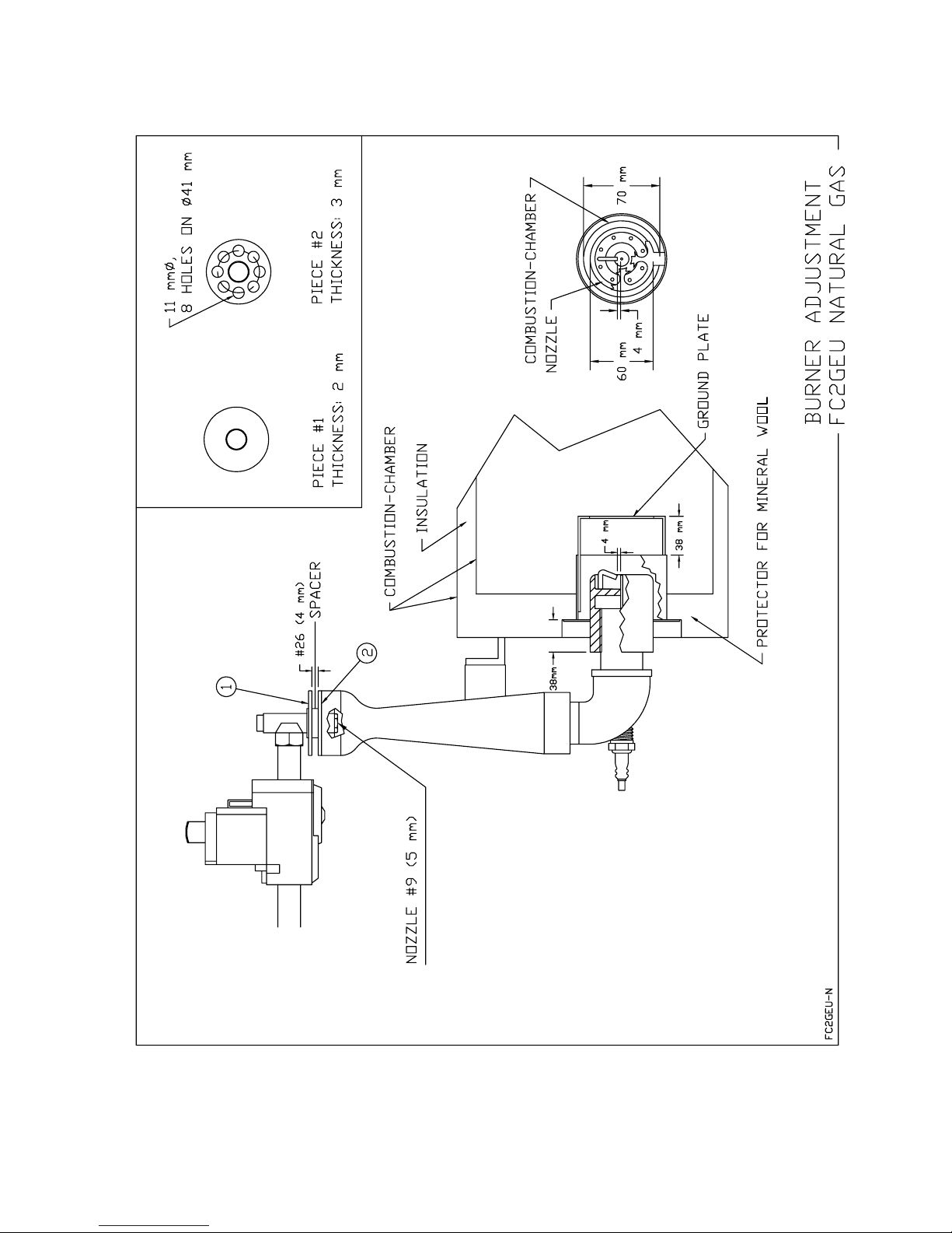
FC2GEU Natural Gas . . . . . . . . . . . . . . . . . . . . . . . . . . . . . . . . . . . . . . . . C3
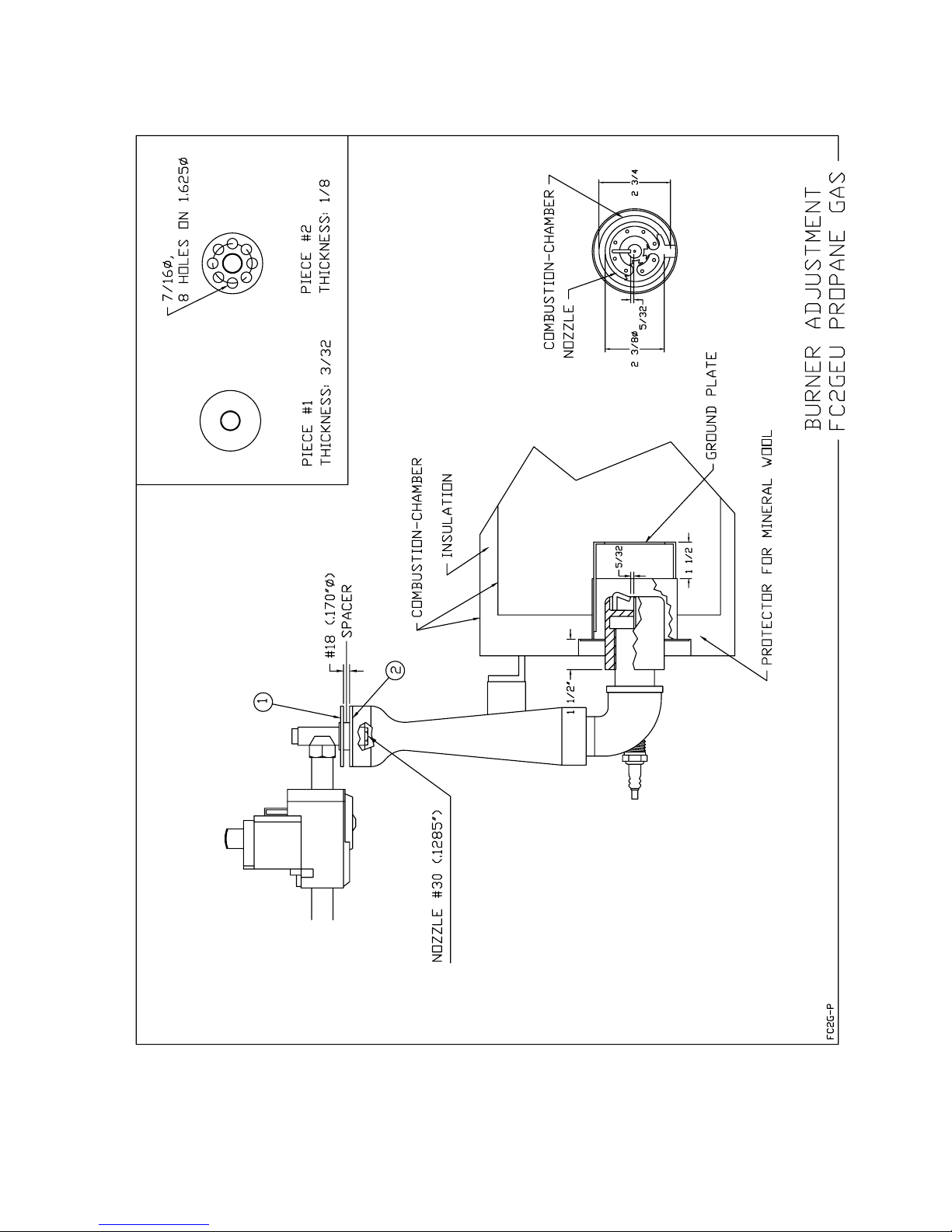
FC2GEU LP Gas . . . . . . . . . . . . . . . . . . . . . . . . . . . . . . . . . . . . . . . . . . . . C4
SECTION « D » HEAT DIFFUSER ADJUSTMENT
FC18GEU. . . . . . . . . . . . . . . . . . . . . . . . . . . . . . . . . . . . . . . . . . . . . . . . . . . D1
Page 2

FC2GEU . . . . . . . . . . . . . . . . . . . . . . . . . . . . . . . . . . . . . . . . . . . . . . . . . . . D2
SECTION « E » COMPONENT PARTS
FC18GEU . . . . . . . . . . . . . . . . . . . . . . . . . . . . . . . . . . . . . . . . . . . . . . . . . . E1
FC2GEU. . . . . . . . . . . . . . . . . . . . . . . . . . . . . . . . . . . . . . . . . . . . . . . . . . . . E9
SECTION « G » ELECTRIC SCHEMATICS
FC18GEU 220V/1PH/50 Hz . . . . . . . . . . . . . . . . . . . . . . . . . . . . . . . .. . . . G1
FC2GEU 220V/1PH/50 Hz . . . . . . .. . . . . . . . . . . . . . . . . . . . . . . . . . . . . .
G2
Global warranty . . . . . . . . . . . . . . . . . . . . . . . . . . . . . . . . . . . . . . . . .. . .
CAUTION
In case of strong gas odours, shut off the gas input valve
and contact a specialised gas technician.
FCGEU_A.DOC Rev. 02-2005
Page 3

A-1
INTRODUCTION
The manufacturer suggests to read this manual carefully.
This Jet Air gas fired oven is manufactured with first quality material by experienced technicians.
Proper installation and maintenance will guarantee a reliable service for years to come.
A nameplate fixed at the back of the oven specifies the model number, serial number, voltage,
amperage and frequency.
Drawings, electrical diagram and replacement part numbers are included in this manual. The
electrical diagram is affixed in the control panel under the hood of the oven.
ATTENTION
DOYON is not responsible for damages to the property or the equipment caused by
personnel who is not certified by known organisations. The customer is responsible for
finding qualified technicians in gas, electricity and plumbing for the installation of the
oven.
CONSTRUCTION
You just bought the most advanced gas fired oven in the world, "DOYON" technology at its best.
This gas fired oven is manufactured using the highest quality components and material.
The oven gives a perfect uniform baking with its unique Jet Air convection system. The DOYON
gas fired oven is designed with parts that are easy to find.
SHIPPING
For your safety, this equipment is verified by qualified technicians and carefully crated before
shipment. The freight company assumes full responsibility concerning the delivery in good condition
of the equipment in accepting to transport it.
IMPORTANT
RECEPTION OF THE MERCHANDISE
Take care to verify that the received equipment is not damaged before signing the delivery receipt. If
a damage or a lost part is noticed, write it clearly on the receipt. If it is noticed after the carrier left,
contact immediately the freight company in order that they do their inspection.
We do not assume the responsibility for damages or losses that may occur during transportation.
Page 4

A-2
INSTALLATION WARNINGS
The DOYON gas fired ovens are designed to be used with the gas specified on the descriptive
nameplate.
THIS APPLIANCE SHALL BE INSTALLED IN ACCORDANCE WITH CURRENT
REGULATION AND USED ONLY IN A WELL VENTILATED SPACE. REFER TO THE
INSTRUCTION BEFORE INSTALLING AND USING THIS APPLIANCE.
THIS APPLIANCE MUST BE INSTALLED IN ACCORDANCE WITH THE
REGULATIONS AND RULES IN FORCE WITHIN THE DESIGNATED COUNTRY OF
DESTINATION.
POWER FAILURE WARNING
WHEN YOU HAVE A POWER FAILURE, SHUT OFF THE OVEN POWER SWITCH TO
PROTECT THE ELECTRONICS COMPONENTS WHEN THE POWER COMES BACK.
FOR YOUR SAFETY
DO NOT STORE OR USE GASOLINE OR OTHER FLAMMABLE VAPOURS
AND LIQUIDS IN THE VICINITY OF THIS OR ANY APPLIANCE.
INSTALLATION AND SERVICE
WARNING
IMPROPER INSTALLATION, ADJUSTMENT, ALTERATION, SERVICE OR
MAINTENANCE CAN CAUSE PROPERTY DAMAGE, INJURY OR DEATH.
READ THE INSTALLATION, OPERATING AND MAINTENANCE INSTRUCTIONS
THOROUGHLY BEFORE INSTALLING OR SERVICING THIS EQUIPMENT.
Installation and service must be done by qualified peoples. Contact a certified gas technician,
electrician and plumber for set up.
Do not permit fans to blow directly at the oven and whenever possible, avoid open windows
next to the oven sides or back and wall type fans which create air cross currents the room.
CAUTION
Make sure that the adjustments mentioned in the "Installation" section are correctly
done prior to firing the oven or converting to a new gas.
Page 5

A-3
DISTANCES TO RESPECT
WARNING
THE SURFACE ABOVE THE BAKING CHAMBER OPENINGS ARE EXTREMELY HOT
AND CAN CAUSE SERIOUS INJURIES
A) Back of the oven: 8 inches (20 cm).
B) Top of the oven: a clearance of 12 inches (30 cm) above the top of the oven must exist to
permit adequate venting of the exhaust pipe, hot parts and to give proper access to a
technician.
C) Floor: 8 inches (20 cm) minimum
D) Sides of the oven: No clearance required from the end of the conveyor. Do not install other
than easily removable equipment for service and maintenance.
Page 6
A-4
INSTALLATION
IN GENERAL
Take off the packaging material with care. Take off all the material used for packing and
accessories.
Each unit is set up to be used with the type of gas and electrical supply specified on the data plate
fixed on the appliance.
THIS APPLIANCE MUST BE INSTALLED IN ACCORDANCE WITH THE
REGULATIONS AND RULES IN FORCE WITHIN THE DESIGNATED COUNTRY OF
DESTINATION.
1. To the certified gas technician.
The burner used is adjusted and sealed for use with the gas indicated on the nameplate. It is
nevertheless possible to convert the burner to another gas. These modifications must be
completed by a certified gas technician to conform to the EN 203-1:1993 (as amended)
standard.
The installation shall be made with a connector that complies with the standard EN 203-1:1993
(as amended)
Clean the air contained in the gas supply pipe at the installation to insure a successful firing on
the first try. The gas pipe sealing compound tightness must be verified using a solution of water
and soap prior to firing the unit.
NOTE: If there's any modification done to the system or change of the type of gas used, make
sure that the regulator pressure of the burner is adjusted as recommended in this manual.
2. To the electrician.
Electrical supply installation must be in accordance with the electrical rating on the nameplate.
Verify if the motor is running in same direction as indicated by the arrow on the motor.
If it’s not the case;
If it’s a three phases motor and if the order of phase isn’t correct, the motor is running in the
wrong direction. This will affect the baking quality. You have to cut off the power supply and
interchange two phases to restore the situation.
WARNING
The electrician must make sure that the supply cable does not come in contact with the
oven top which becomes hot.
Page 7
A-5
)
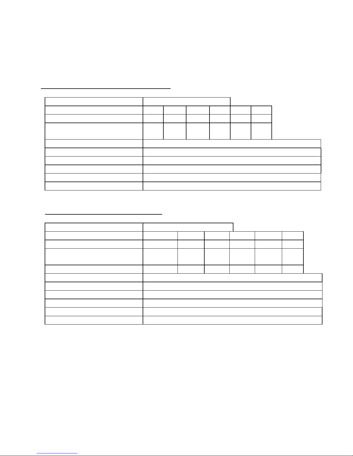
Technical Data for the FC18GEU natural gas
Declared input (kW) 15.00
Gas Group I
2H
I
2E(R)BI2Er
I
2ELLI2E
I
2L
Inlet pressure (mbar) 20 20/25 20/25 20 20 20
Declared setting pressure at the
8.75 8.75 8.75 8.75 8.75 8.75
outlet from the gas valve (mbar)
Main burner type Power burner manufactured by Doyon
Number of injectors 1
Main injector type Single drilled hole marked **********************
Main injector size and markings #29 (3mm)
Main burner aeration opening size Fully adjusted aeration shutter set and sealed in production
Ignition Electronic directly to the burner
Technical Data for the FC18GEU LP gas
Declared input (kW) 17.00
Gas Group I
3+
I
3B/P(30)I3P(30)
I
3P(37)
I
3B/P(50)I3P(50
Inlet pressure (mbar) 28-30/37 30 30 30 50 50
Declared setting pressure at the
outlet from the gas valve (mbar)
18.75 18.75 18.75 18.75 18.75 18.7
5
Main burner type Power burner manufactured by Doyon
Number of injectors 1
Main injector type Single drilled hole marked **********************
Main injector size and markings #42 (2mm)
Main burner aeration opening size Fully adjusted aeration shutter set and sealed in production
Ignition Electronic directly to the burner
Page 8
A-6
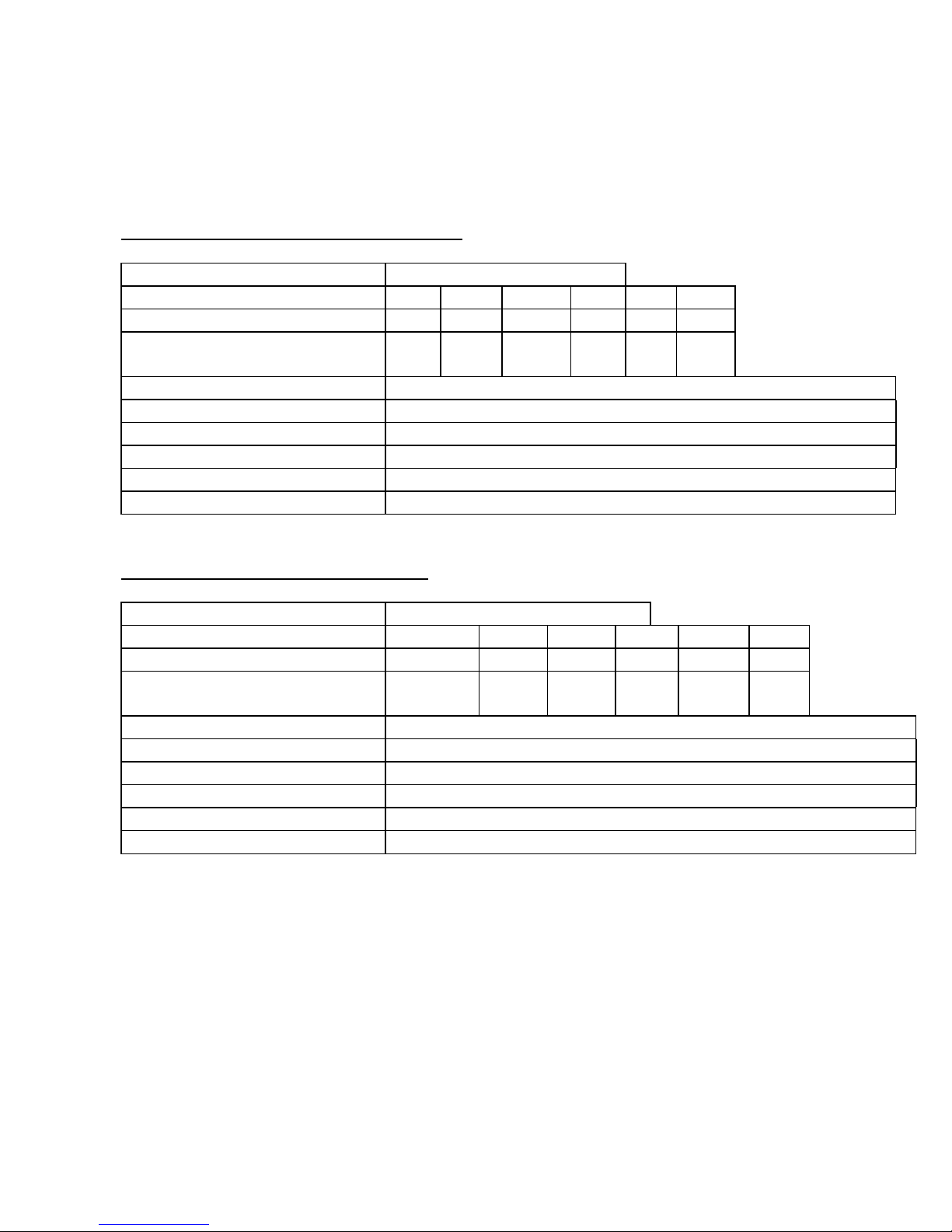
Technical Data for the FC2GEU natural gas
Declared input (kW) 31.00
Gas Group I
2H
I
2E(R)BI2Er
I
2ELLI2E
I
2L
Inlet pressure (mbar) 20 20/25 20/25 20 20 20
Declared setting pressure at the
8.75 8.75 8.75 8.75 8.75 8.75
outlet from the gas valve (mbar)
Main burner type Power burner manufactured by Doyon
Number of injectors 1
Main injector type Single drilled hole marked **********************
Main injector size and markings #9 (5mm)
Main burner aeration opening size Fully adjusted aeration shutter set and sealed in production
Ignition Electronic directly to the burner
Technical Data for the FC2GEU LP gas
Declared input (kW) 35.00
Gas Group I
3+
I
3B/P(30)I3P(30)
I
3P(37)
I
3B/P(50)I3P(50)
Inlet pressure (mbar) 28-30/37 30 30 30 50 50
Declared setting pressure at the
18.75 18.75 18.75 18.75 18.75 18.75
outlet from the gas valve (mbar)
Main burner type Power burner manufactured by Doyon
Number of injectors 1
Main injector type Single drilled hole marked **********************
Main injector size and markings #30 (3.3mm)
Main burner aeration opening size Fully adjusted aeration shutter set and sealed in production
Ignition Electronic directly to the burner
Page 9

A-7
USER OPERATION INSTRUCTION
WARNING
THE SURFACE ABOVE THE BAKING CHAMBER OPENINGS ARE EXTREMELY HOT
AND CAN CAUSE SERIOUS INJURIES
“This appliance is only for professional use and should be used by qualified persons only"
1. Open the main gas valve.
2. Turn on the ventilation system if necessary.
3. Turn the switches to the position "ON" (turn on both switches, "main switch" and "oven start
switch"). See page A9 or A10 for operation description.
• The green light "READY FOR OPERATION" must turn on for a few seconds (it
indicates that every starting condition is present)
• The blower starts and the burner fires if the thermostat is adjusted over the ambient
temperature (the green light "BURNER" indicates that the burner is fired).
(If nothing happened, press the breakers on the front)
4. Adjust the thermostat at the desired setting (see THERMOSTAT INSTRUCTIONS bellow).
5. Wait until the unit reaches the baking temperature (see tables "Pizza baking time").
• When the desired temperature is reached, the red light (on the thermostat) goes out
and turns green then the burner stops.
6. Adjust baking time according to your product (see suggestions “Pizza baking time”).
Use the arrows up/down on the micro drive.
7. Place your products on the conveyor.
Use a screen for a regular pizza and use pan for a pan pizza.
IMPORTANT:
To stop the oven, turn the "oven start switch" to the position "OFF"( the blower will run for
15 minutes and temperature will decrease quickly to avoid electronic components to get too hot).
Use the red emergency switch only in case of an emergency.
POWER FAILURE
The burner, the electric gas valve and the regulator are all designed to be fail safe. Then, there is
no special action to take in case of electrical power failure. Turn off the oven. Never leave the
oven unsupervised when the power is on the unit.
THERMOSTAT INSTRUCTIONS
The temperature of the oven is always shown on the display of the thermostat and an arrow
indicates if the temperature is over the SP (set point) or below. When the green light is lit, it
indicates that the temperature is at the SP ± 1 %.
Page 10

A-8
To adjust the SP value, you just have to press the left key and use the up and down keys to set
temperature value. Press the left key to return to run mode.
FAULT DESCRIPTION
When there is a fault, a buzzer rings and the red light "fault" turns on
It may be caused by
• Too much pressure in burner compartment (blower does not work or does not produce
vacuum) air pressure switch is not well adjusted or defective.
• Gas pressure is too low or not well adjusted or defective gas pressure switch.
• Malfunction of ignition system or detection of flame.
To correct it, wait 10 seconds and press the red push button "fault" (same one as the "fault" light).
If the fault is still active and cannot be reset, call for service.
Cooling fans
Two cooling fans run during normal operation of the oven.
A temperature detector (thermodisk) is installed in the control compartment to start the three
cooling fans when the temperature rises over 110 °F.
Page 11
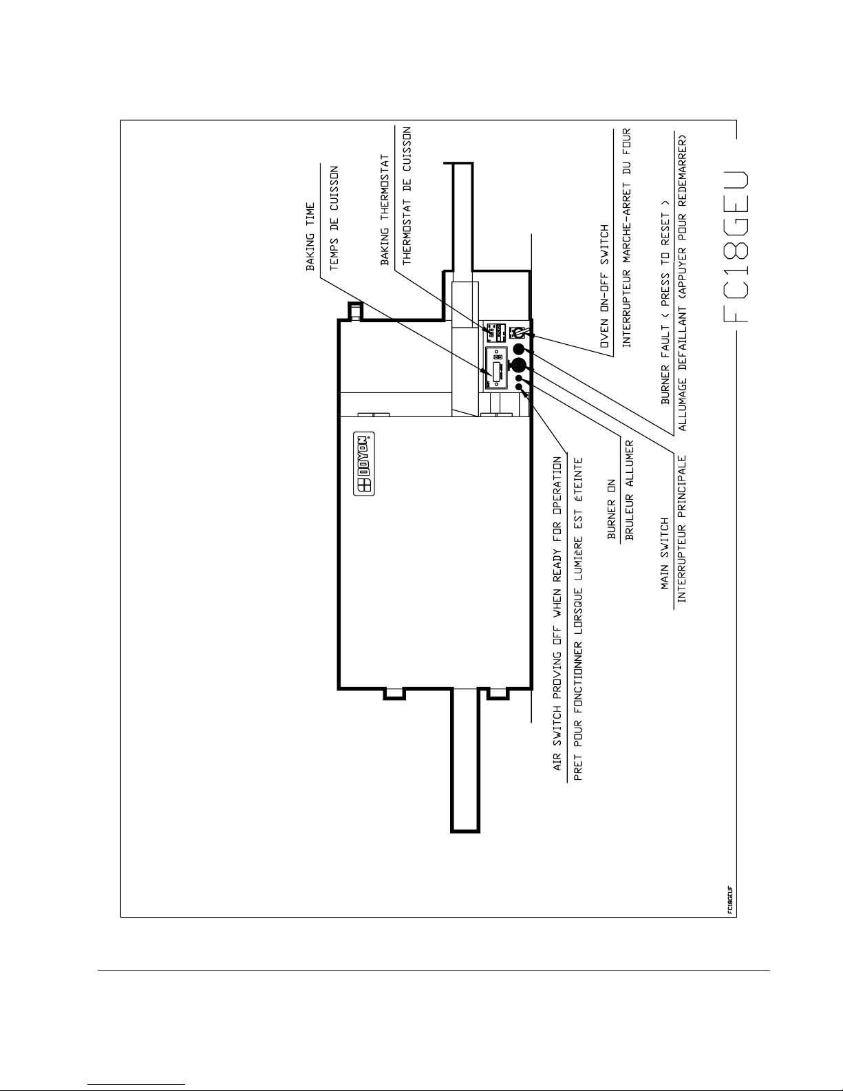
A-9
Page 12
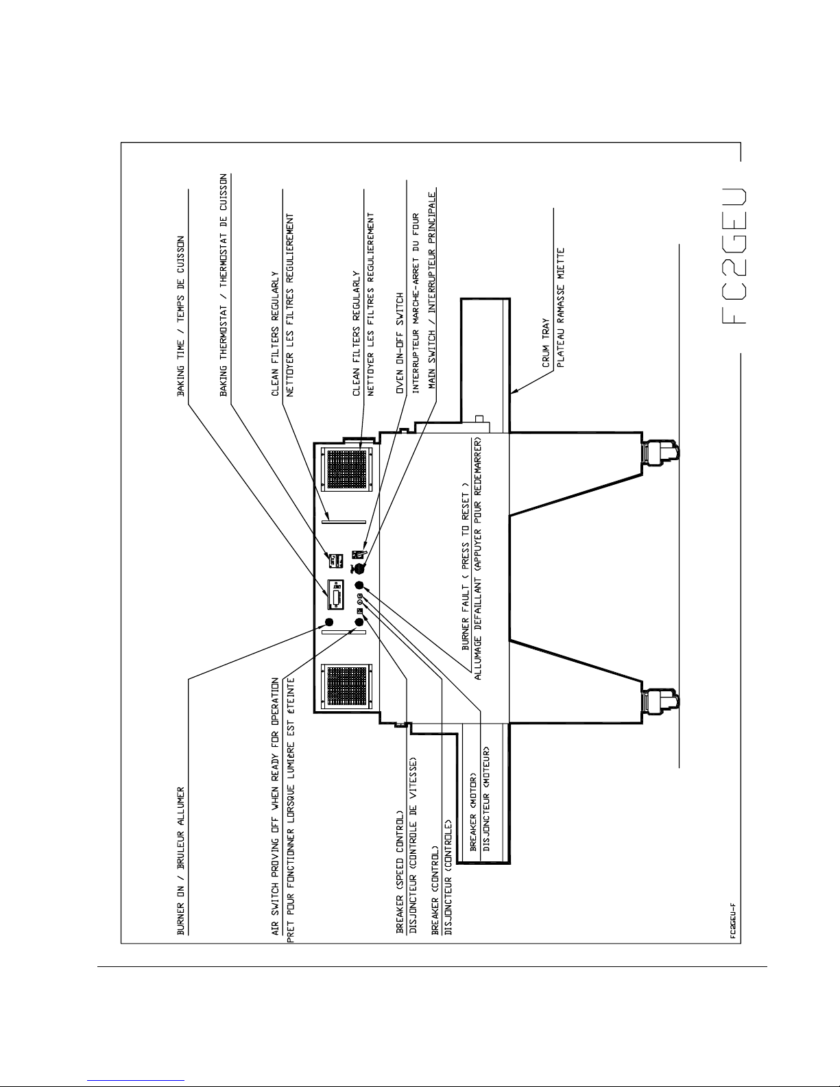
A-10
Page 13
A-11
COOKING TIME AND TEMPERATURE RECOMMENDATION
REGULAR PIZZA BAKING TIME
Temperature Pizza Approximate baking time
280°C PEPPERONI 5.00 minutes
280°C ALL DRESS 5.20 minutes
270° C EXTRA TOPPING 6.00 minutes
255° C SPECIAL HOUSE 7.00 minutes
PIZZA PAN BAKING TIME
Temperature Pan pizza Approximate baking time
2600 C ALL DRESS 7.20 minutes
IMPORTANT: You must adjust your baking time according to your own recipe. We
recommend that you conduct a few baking tests at the beginning and note your time for
future reference.
Page 14
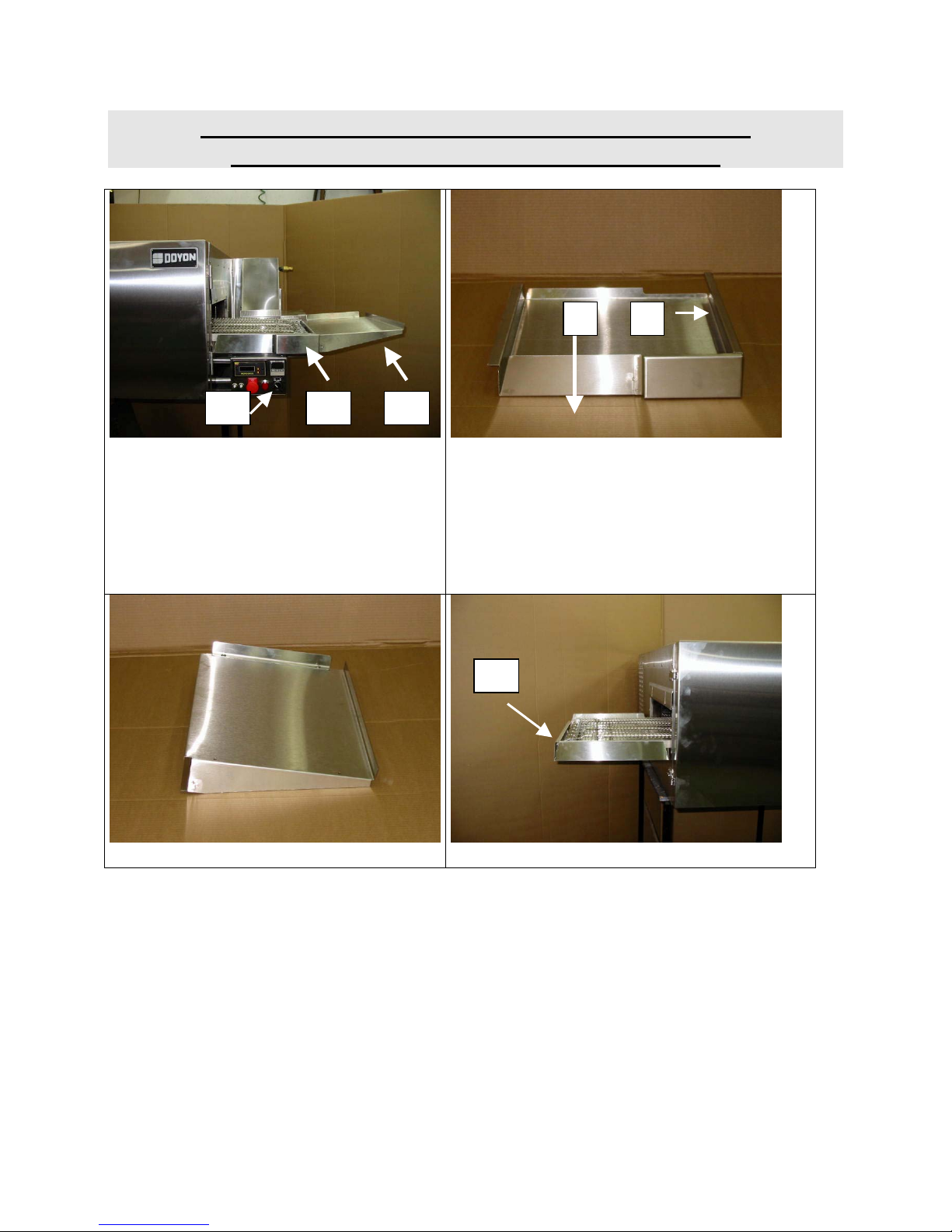
A-12
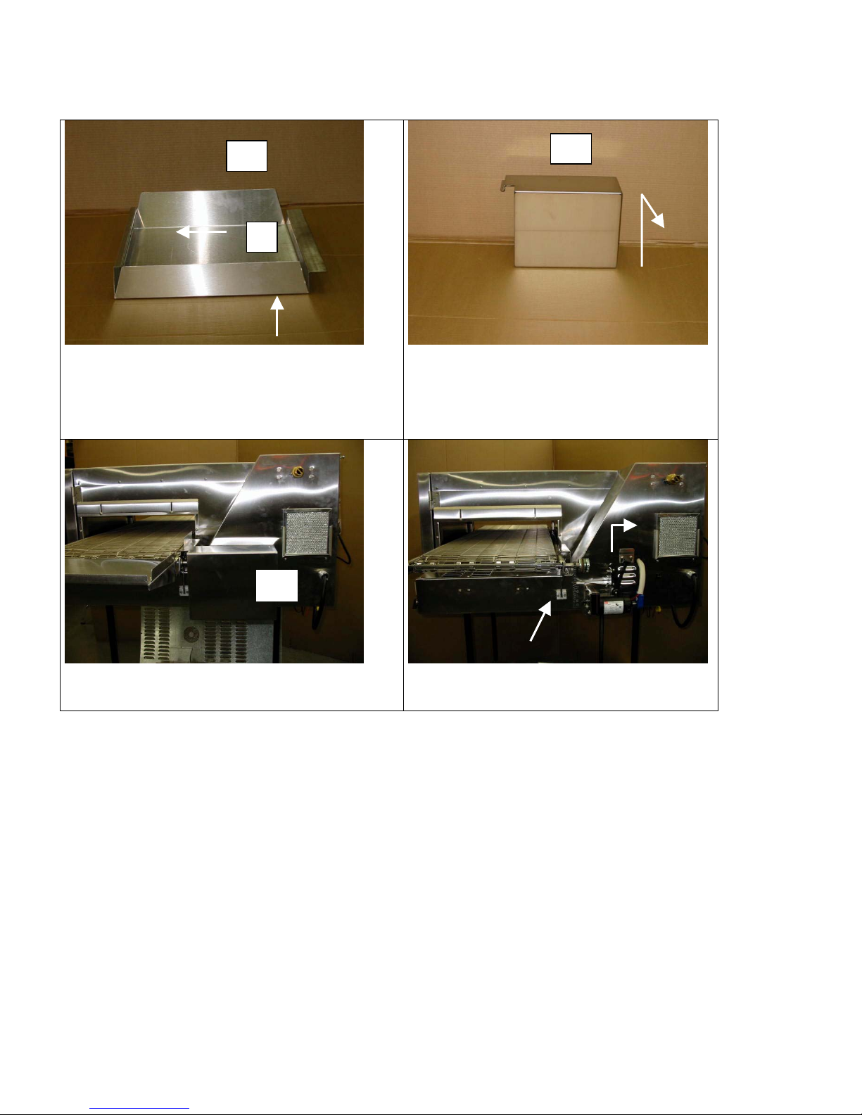
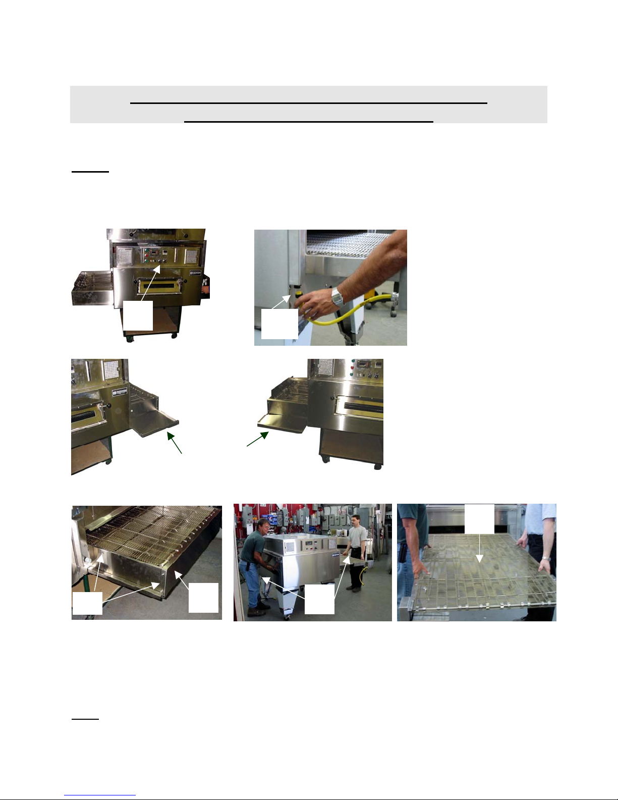
INSTRUCTIONS TO REMOVE THE CONVEYOR
AND CLEAN THE OVEN ONTHE FC18GEU
12
A C B
1. Turn the power off ( A ).
♦ Remove the extended shelf ( B ).
♦ Remove the right tray ( C ).
3. Right tray ( C ).
♦ To remove the tray :
♦ Push ( 1 ) to the left (5mm),then lift
(10mm), then pull to the right ( 3cm )
♦ Pull the tray in the same direction as
indicated in ( 2 ) above.
D
2. Extended shelf ( B ). 4. Left tray ( D ).
Page 15
A-13
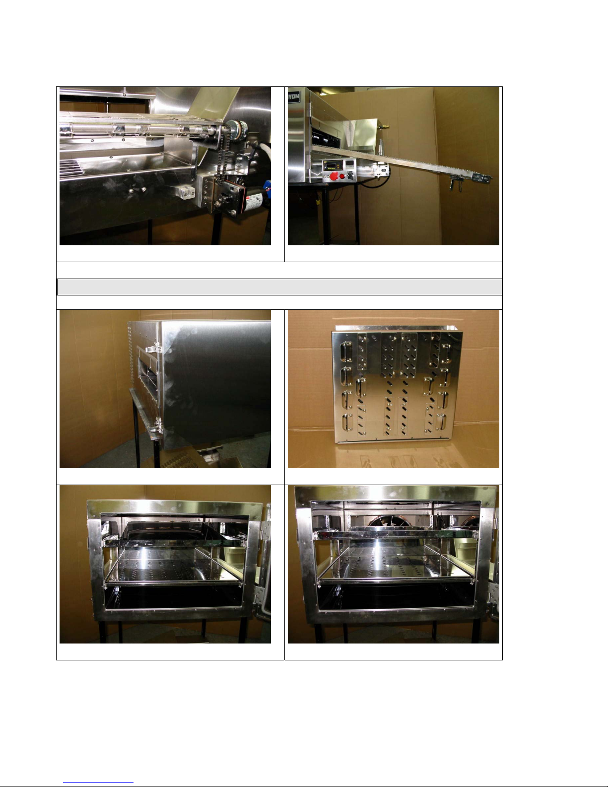
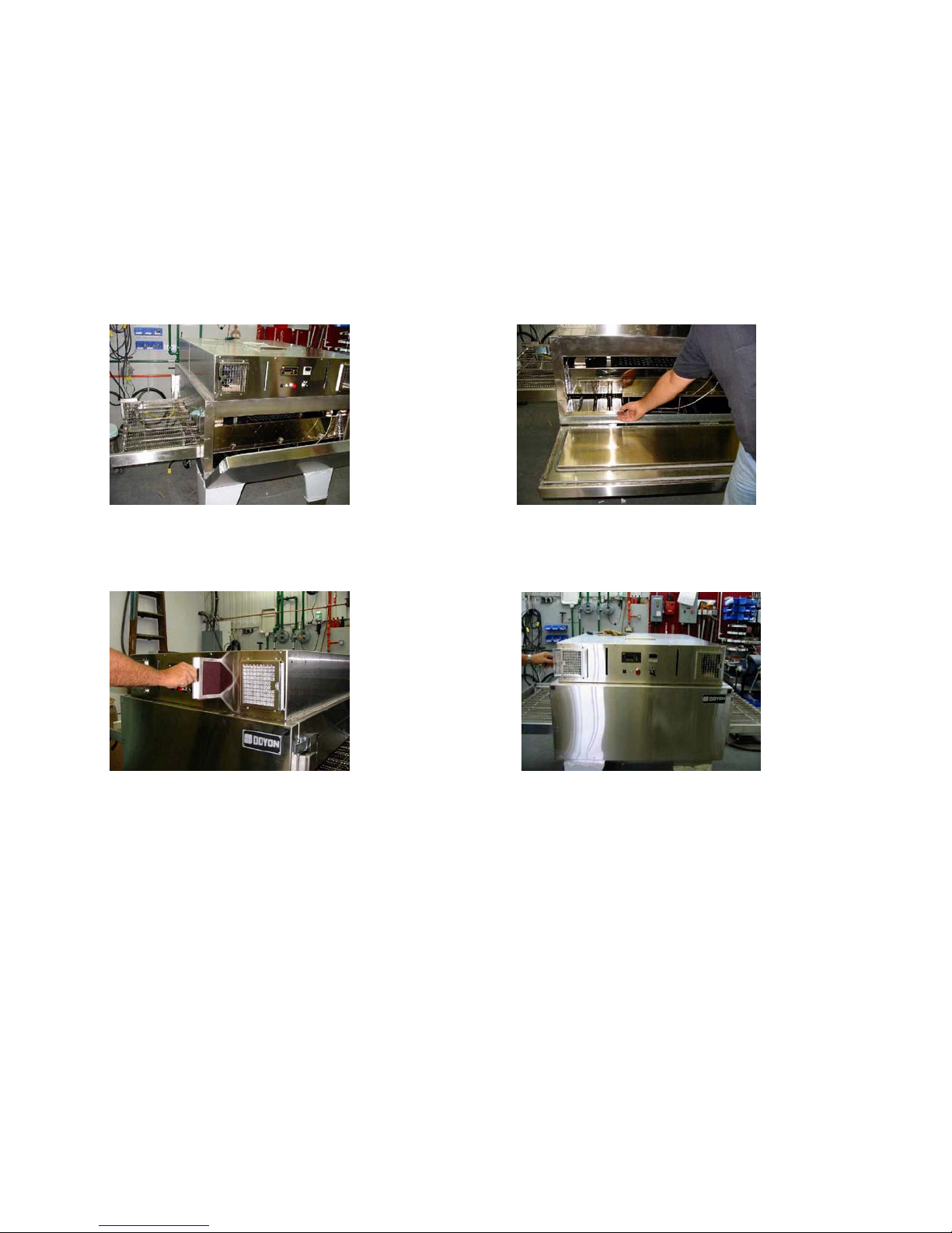
D
1
5. Left tray ( D ).
♦ To remove the tray :
♦ Push ( 1 ) to the right (5mm),then lift
(10mm), then pull to the left.
E
7. Remove gearbox cover ( E ).
♦ Lift ( 2cm ).
♦ Pull away from oven.
E
6. Remove gearbox cover ( E ). 8. Remove rubber strap.
♦ Lift gearbox to remove the chain.
Page 16
A-14
9. Lift conveyor ( 2cm ) and pull it out. 10. Remove conveyor completely.
INTERIOR SECTION
11. Open the door. 13. Top heat diffuser.
12. Remove the heat diffusers. 14. Interior without top heat diffuser.
Page 17
A-15
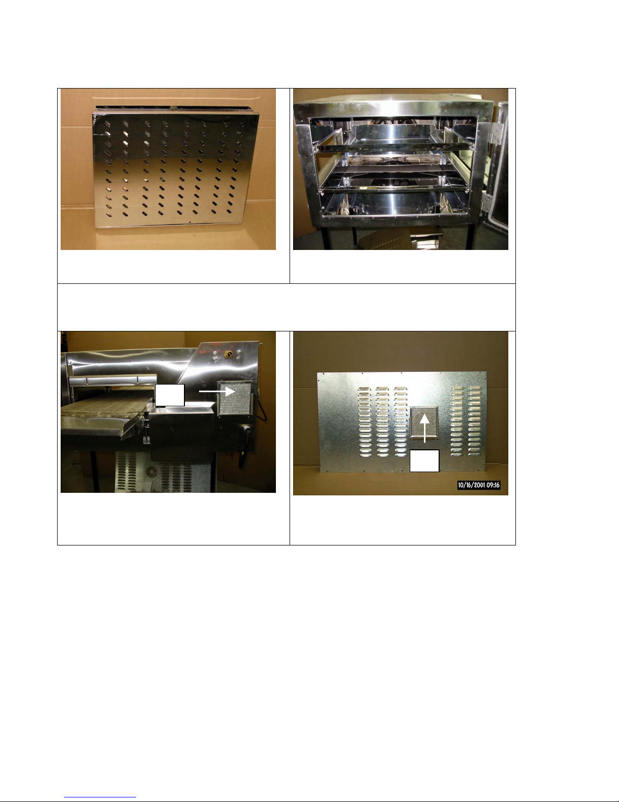
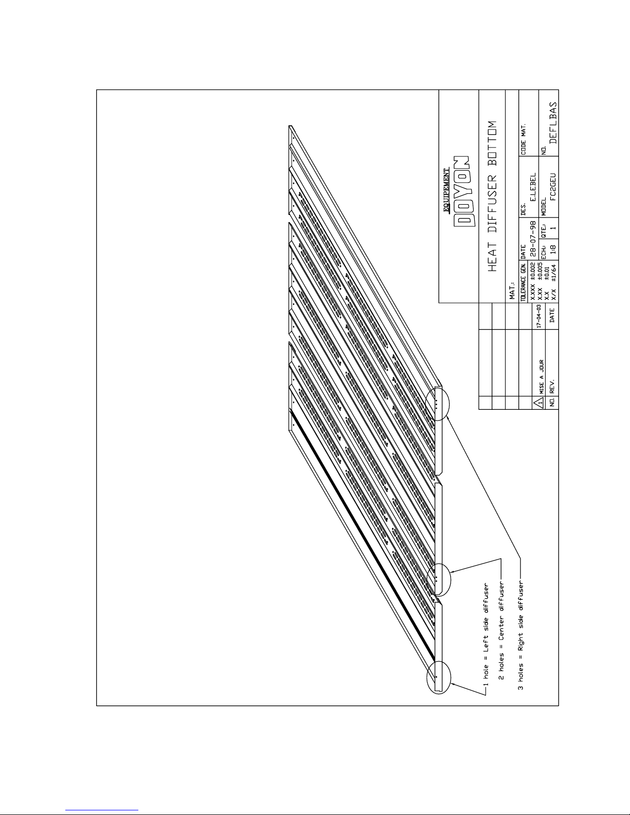
15. Remove bottom heat diffuser. 16. Interior without top and bottom
heat diffuser.
FILTERS
F
17. The filters ( F,G ) must be cleaned
regularly, to maintain a good
ventilation.
G
18. The filters may be cleaned with
water and dishwashing liquid or
replaced by a new filter.
Page 18
A-16
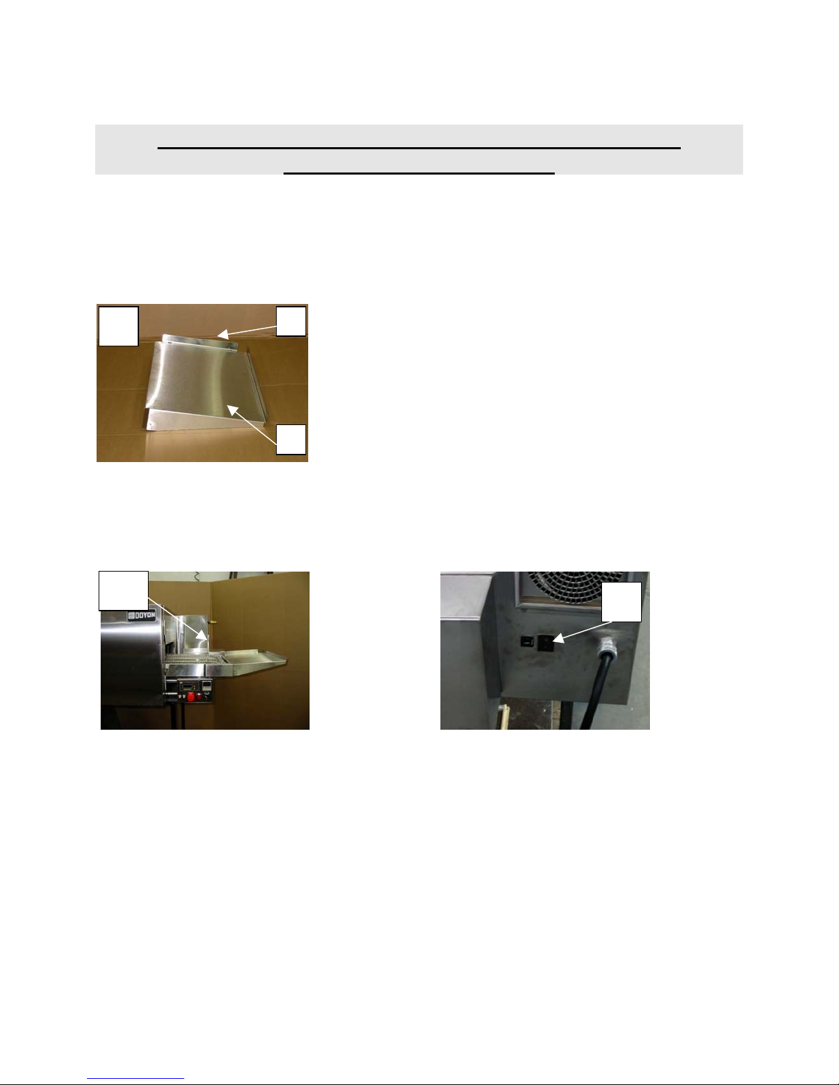
INSTRUCTIONS TO REVERSE DIRECTION OF THE
CONVEYOR ON FC18GEU
When you reverse the conveyor direction, you have to install the extension shelf on the other side of
the conveyor (see picture A). Unscrew the pizza stopper [1] and screw to the other side of the
extension [2].
A 1
2
To reverse the direction of the belt change the position of the switch located beside (picture D and
E) the conveyor motor from position I to II.
WARNING: Shut off the main power switch of the oven before reversing the conveyor.
D
E
Page 19
A-17
INSTRUCTIONS TO REMOVE THE CONVEYOR
AND CLEAN THE OVEN FC2GEU
NOTE: In order to remove the conveyor, it is necessary to be two people.
1- Place the oven main switch [A] to the position "OFF" (see drawing previous pages).
2- Make sure that the oven has cooled down completely.
3- Disconnect the yellow plug of the conveyor motor [B] (unscrew the plug).
A
4- Remove the two crumb trays located under the conveyor [C].
C C
5- Take out the screws which holds the end finishing plate and the two side finishing
plates on each side of the conveyor [D] and remove the finishing plate. [E]
E
D
6- To take out the conveyor, it takes two people, one at each end. The person who is at
the opposite side of the gear motor of the conveyor raises it 1 inch (2 cm) and pushes
it towards the front. When the end of the conveyor is inside the oven, it is preferable
that the same two people place themselves on each side of the conveyor and continue
to pull with precaution to take out the conveyor completely.
7- To re-install the conveyor, repeat the instructions above in reverse.
Note: It is possible to reverse the conveyor. When you are ready to re-install, just enter it at
the opposite side of the oven.
B
6
6
Page 20
A-18
INTERIOR:
1-Remove the conveyor (see PAGE A11).
2-Open the door. 3-Remove the 3 bottom deflector panels.
4-Clean the interior of the oven, the 3 bottom deflector panels and the conveyor with oven cleaner
(EASY OFF or MR. MUSCLES).
5-Clean the air filter located on the front of the oven. Use water and soap.
EXTERIOR:
Use stainless steel cleaner.
We recommend and sell Product # NES 201.
Page 21

A-19
INSTRUCTIONS TO REVERSE DIRECTION OF THE
CONVEYOR ON FC2GEU
(See drawings and pictures on the following pages)
NOTE: In order to reverse the FC2 conveyor, it's necessary to be two persons.
1- Place the main switch to the position "OFF". (A)
2- Make sure that the oven has cooled down completely.
3- Disconnect the conveyor. (Unscrew the conveyor plug) (B)
4- Remove the two plates located under the conveyor. (C)
5- Take out the screws which holds the end finishing plate and the two side finishing plates
of the conveyor (D) and remove these plates. (E)
6- To take out the conveyor, it takes two persons, one at each end. The person who is at the
opposite end of the conveyor motor gearbox of the conveyor raises it 1" (2.5 cm) (F) and
pushes it through the oven (G). When the end of the conveyor is inside of the oven, it is
preferable that the same two persons place themselves on each side of the conveyor and
continue to pull with precaution to take out the conveyor completely.
7- To reinstall the conveyor, enter it at the opposite end and repeat the above instructions in
reverse.
Page 22

A-20
Page 23
A-21
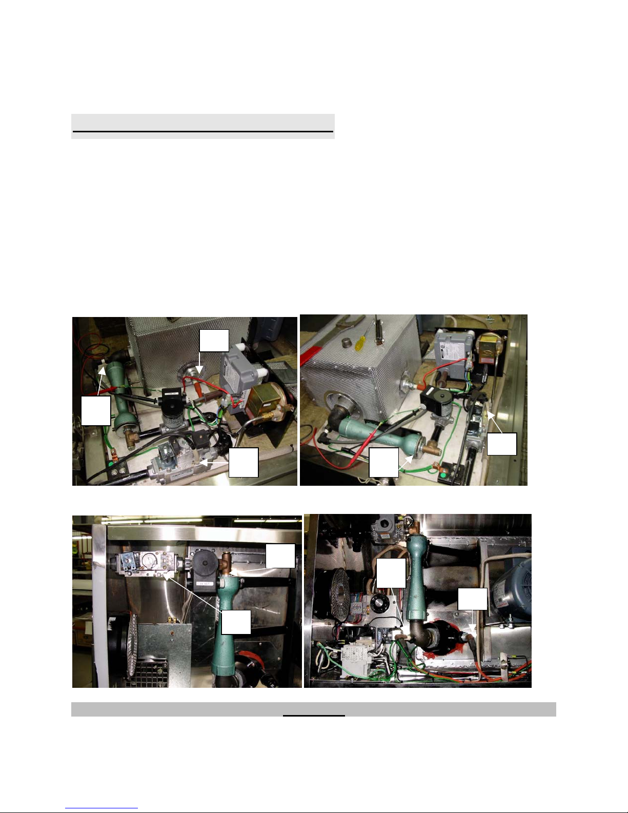
MAINTENANCE OF THE BURNER
Once a year, you should ask a certified technician to make a tune up.
Make sure everything works properly, verify and clean especially:
1 The gas mixer air inlet
2 The spark rod and porcelain insulators
3 The flame detection rod
4 Verify the burner input pressure
5 Verify every adjustments (Ignition rod gap, microamps on the detection and air inlet opening)
6 Clean every moving pieces
FC2GEU
3
2
FC18GEU
4
4
1
4
1
2
3
Keep this operating manual for future reference.
WARNING
Page 24
A-22
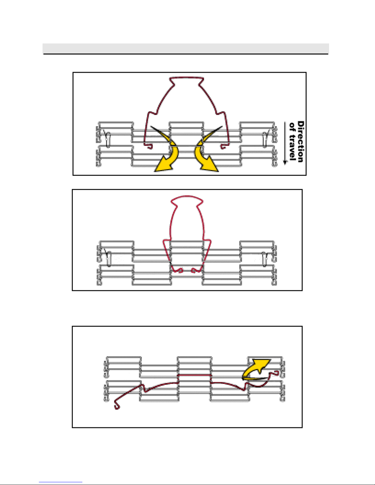
INSTRUCTIONS TO REMOVE THE BELT ON THE CONVEYOR
Page 25

A-23
Page 26

A-24
Page 27

A-25
Page 28
A-26
TROUBLESHOOTING
BEFORE CALLING FOR SERVICE
ANSWERS TO MOST FREQUENT QUESTIONS
Questions Solutions
The oven is "ON", but does not function.
The fan runs but the oven does not heat.
The red light on the front control panel is on
and the alarm rings.
The oven heats too much or does not
produce enough heat.
The conveyor chain is not tight enough.
• Check the main breaker (the one on the
building panel) and also the breaker located
at the front of the oven (5 amps).
• Check if the thermostat is adjusted high
enough to fire the oven.
• Check the main gas valve.
• To start it over, press the red button on the
front control panel for 2 seconds. The burner
will start up (you can hear it). You can
repeat this operation three times. If it does
not start up again, contact our company or a
certified gas technician.
Measure the temperature with an oven
thermometer and compare it with the
temperature indicated on the thermostat.
To tighten:
• Take off the protector at the end of the speed
control located on the sides of the conveyor.
With a 7/16" key, lightly unscrew the 2
screws having an adjustment on each side;
• Tighten the belt of the conveyor and the
screws;
• Put back the protectors.
The conveyor does not turn.
• Check the 0.75 amps breaker on the front
for FC2GEU or on the side for FC18GEU of
the oven.
• If the breaker is "tripped", check if the
conveyor is free from any obstructions
before resetting the breaker.
• Check the conveyor main shaft if the
security clutch is not slipping.
Page 29

A-27
FOR MORE INFORMATION,
PLEASE CONTACT OUR OFFICE :
DOYON EQUIPMENT INC.
1255, rue Principale,
Linière, Qc, Canada G0M 1J0
TEL. : (418) 685-3431
FAX : (418) 685-3948
Internet: http://www.doyon.qc.ca
E-Mail : doyon@doyon.qc.ca
Page 30

SECTION
B
DIMENSIONS
Page 31

B-1
Page 32

B-2
Page 33

B-3
Page 34

B-4
Page 35

B-5
Page 36
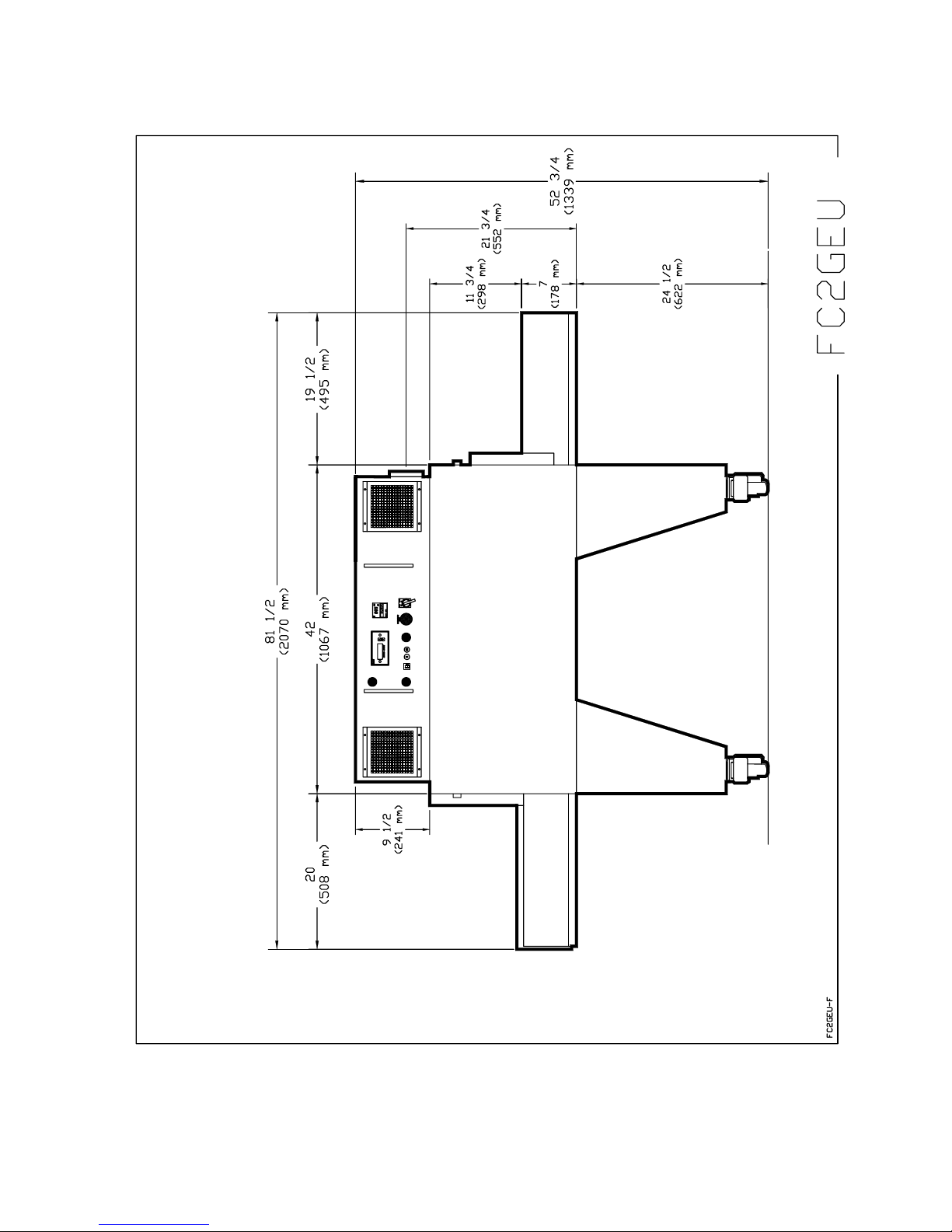
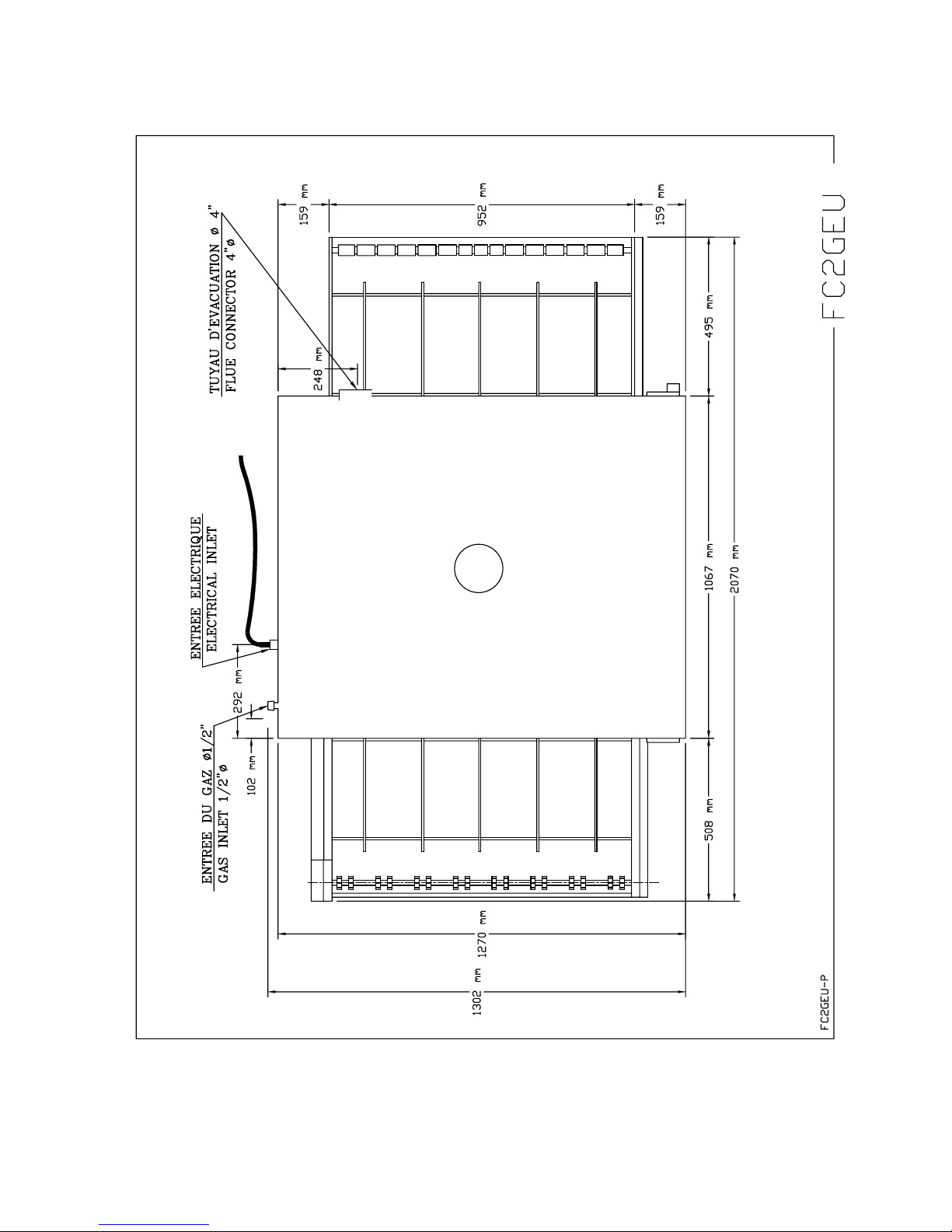
B-6
Page 37

B-7
Page 38
B-8
Page 39

SECTION
C
BURNER AJUSTMENT
Page 40

C-1
Page 41
C-2
Page 42
C-3
Page 43
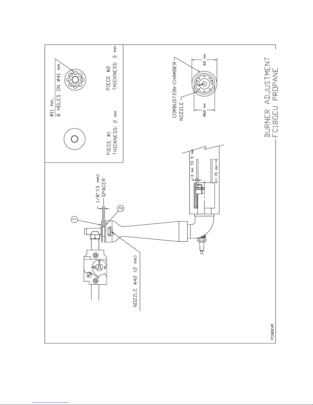
C-4
Page 44

SECTION
D
HEAT DIFFUSER ADJUSTMENT
Page 45
D-1
Page 46

D-2
Page 47
D-3
Page 48

D-4
Page 49

SECTION
E
COMPONENT PARTS
Page 50
E-1
Page 51

E-2
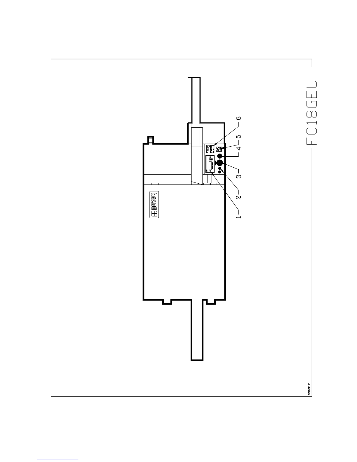
Item Part Number Description Quantity
1 ELM960 CONVEYOR CONTROL MOTOR DART 1
2 ELL675 GREEN PILOT LIGHT 2
3 ELP991 EMERGENCY SWITCH KNOB 1
AND ELI575 CONTACT BLOCK 1NC 1
4 ELL755 PUSH BUTTON SOCKET (N.C.) 1
AND ELL780 HIGHLITED PUSH BUTTON SOCKET 1
AND ELL790 MINI LAMP (220V) 1
5 ELI550 MAIN SWITCH (SELECTOR) 1
AND ELI570 CONTACT BLOCK 2NO 1
AND ELI556 ON - OFF PLATE 1
6 ELT515 OMRON THERMOSTAT E5CS 1
AND ELT532 THERMOCOUPLE TYPE K 1
Model : FC18GEU View : FRONT
Page 52

E-3
Page 53

E-4
Item Part Number Description Quantity
1 ELM940 CONVEYOR MOTOR GEARBOX 1
2 ELM961 PULSE GENERATOR, DART 1
3 ELB089 .75 AMP BREAKER 1
4 50093010 SPROCKET CLUTCH ASSEMBLY 1
5 ELI638 CONVEYOR SWITCH 1
6 ELB112 ETA 5 AMPS BREAKER 1
7 ELB113 ETA 15 AMPS BREAKER 1
8 ELF200 AC FILTER 1
Model : FC18GEU View : SIDE
Page 54

E-5
Page 55
E-6
Item Part Number Description Quantity
1 ELM764 220V 250 CFM BLOWER 1
2 ELT680 THERMOSTAT 700°F 1
AND ELT681 THERMOSTAT KNOB 700°F 1
AND ELT620 THERMOSTAT BEZEL 1
3 GAM200 ATMOSPHERIC MIXER 1
4 GAC270 GAS VALVE REGULATOR VR4605A 230 VOLTS 50 HZ 1
AND GAC271 WIRE HARNESS FOR GAC270 1
AND GAC272 FLANGE FITHING FOR GAS VALVE GAC270 2
4A GAC280 SOLEINOID GAS VALVE 24 VOLTS 50HZ 1
5 ELM800M MOTOR .75HP 1PH 115/208-230V 60Hz/50Hz A.O. SMITH 1
OR ELM820M MOTOR 3/4HP 3PH 208/230/460V 60Hz/50Hz A.O. SMITH 1
AND STR400 SHAFT EXTENSION 1
AND STF425 MOTOR COOLING FAN 1
6 GAP300 PRESSURE SWITCH DWYER 1
7 QUC900 CONVEYOR CHAIN 18" WIDE 1
8 ELT705 TRANSFORMER 120/240 A 12/24, 100VA 1
9 GAB530 ELECTRONIC IGNITION CONTROL RAM-5EM7-01 1
10 GAD200 FLAME DETECTION ROD 1
11 ELM761 COOLING FAN 1
12 (220VOLTS 1 PHASE 50Hz PANEL) 1
13 ELS970 BUZZER 1
14 ELT507 HIGH TEMPERATURE LIMIT SWITCH 110°F 1
15 ELB073 TERMINAL BLOCK 30A 5
16 ELM735 SOLID STATE TIMER ICM FOR CH460,JAOP3-G, FC2-G
1
AND E233
17 GAD190 IGNITION ROD 1
Model : FC18GEU View : BACK
Page 56

E-7
Page 57
E-8
Item Part Number Description Quantity
1 ELC903 MOTOR CONTACTOR TÉLÉMÉCANIQUE. COIL 220 V
1
50/60Hz
2 ELO101 OVERLOAD TÉLÉMÉCANIQUE 4-6 AMPS 1
& ELO125 OVERLOAD BASE RELAY TÉLÉMÉCANIQUE 1
3 ELM720 OMRON CONTROL TIMER (11 PIN) H3CR 2
& ELM729 11 PIN BASE 2
Model : FC18GEU View : BACK INSIDE
Page 58

E-9
Page 59
E-10
Item Part Number Description Quantity
1 ELM961 PULSE GENERATOR, DART 1
2 ELM940 CONVEYOR MOTOR GEARBOX 1
3 ELM761 COOLING FAN 3
4 ELL675 GREEN PILOT LIGHT 2
5 ELL750 PUSH BUTTON SOCKET (N.O.) 1
AND ELL780 HIGHLITED PUSH BUTTON SOCKET 1
AND ELL790 MINI LAMP (220V) 1
6 ELB113 ETA 15 AMPS BREAKER 1
7 ELB112 ETA 5 AMPS BREAKER 1
8 ELM960 CONVEYOR CONTROL MOTOR DART 1
9 ELT515 OMRON THERMOSTAT E5CS 1
10 ELI550 MAIN SWITCH (SELECTOR) 1
AND ELI555 CONTACT BLOCK 1NO 1
11 ELP991 EMERGENCY SWITCH KNOB 1
AND ELI575 CONTACT BLOCK 1NC 1
12 QUF100 FILTER 2
13 ELB089 .75 AMP BREAKER 1
14 50093010 SPROCKET CLUTCH ASSEMBLY 1
AND QUC305A #25 CHAIN FOR FC2 & FC18 1
Model : FC2GEU View : FRONT
Page 60

E-11
Page 61

E-12
Item Part Number Description Quantity
1 ELM800LS MOTOR .75HP 1PH 115/230V 60 OR 50Hz 1
OR ELM800ML MOTOR 1 PH. 3/4 HP.MAGNETEK WITH 6 1/4 INCHES
1
SHAFT.
OR ELM820LS MOTOR .75HP 3PH 200/600V 60 OR 50Hz 1
OR ELM820ML MOTOR 3 PH. 3/4 HP. MAGNETEK WITH 6 1/4 INCHES
1
SHAFT.
2 GAP300 PRESSURE SWITCH DWYER 1
3A GAD190 IGNITION ROD 1
3B GAD200 FLAME DETECTION ROD 1
4A GAC270 GAS VALVE REGULATOR 230 VOLTS 50 HZ 1
AND GAC271 WIRE HARNESS FOR GAC270 1
AND GAC272 FLANGE FITHING FOR GAS VALVE GAC270 2
4B GAC280 SOLEINOID GAS VALVE 24 VOLTS 50HZ 1
5 GAM200 ATMOSPHERIC MIXER 1
AND GAM210 FLAME RETENTION PIPE PYRONIX 1
6 ELC903 MOTOR CONTACTOR TÉLÉMÉCANIQUE. COIL 220 V
1
50/60Hz
7 ELO101 OVERLOAD TÉLÉMÉCANIQUE 4-6 AMPS 1
AND ELO125 OVERLOAD BASE RELAY TÉLÉMÉCANIQUE 1
8 ELM720 OMRON CONTROL TIMER (11 PIN) H3CR 2
9 ELM729 11 PIN BASE 2
10 ELT507 HIGH TEMPERATURE LIMIT SWITCH 110°F 1
11 ELT680 THERMOSTAT 700°F 1
12 GAB530 ELECTRONIC IGNITION CONTROL RAM-5EM7-01 1
13 ELS960 BUZZER 240 VOLTS 1
14 ELF200 AC FILTER 1
15 QUC910 CONVEYOR CHAIN 36" WIDE 1
16 ELM735 SOLID STATE TIMER ICM FOR CH460,JAOP3-G, FC2-G
1
AND E233
17 ELT705 TRANSFORMER 120/240 A 12/24, 100VA 1
Model : FC2GEU View : TOP
Page 62

SECTION
G
ELECTRIC SCHEMATICS
Page 63
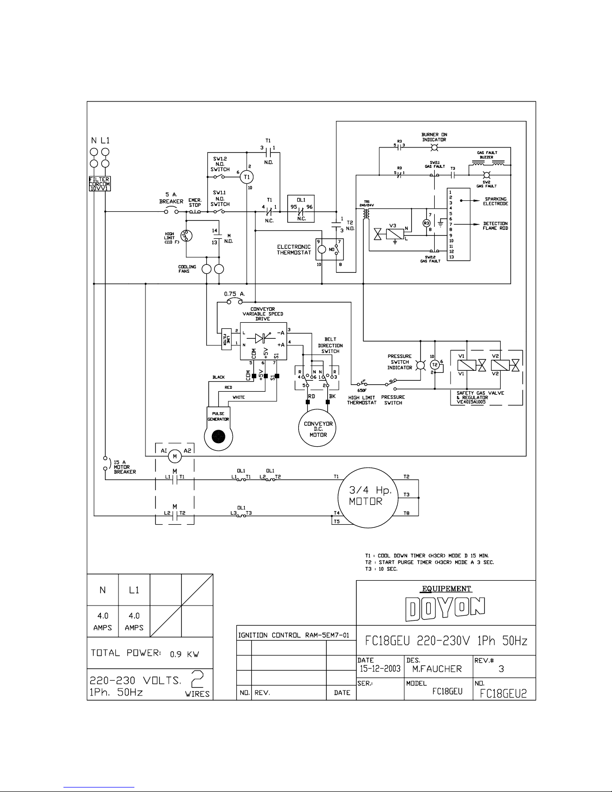
G-1
Page 64

G-2
Page 65

40
 Loading...