

Page 1

GAS CONVEYOR OVEN
FC18G & FC2G
IMPORTANT SAFETY INSTRUCTIONS
SAVE THESE INSTRUCTIONS
TABLE OF CONTENTS
SECTION « A » DESCRIPTION PAGE
Introduction. . . . . . . . . . . . . . . . . . . . . . . . . . . . . . . . . . . . . . . . . . . . . . . . . A1
Construction . . . . . . . . . . . . . . . . . . . . . . . . . . . . . . . . . . . . . . . . . . . . . . . . A1
Shipping . . . . . . . . . . . . . . . . . . . . . . . . . . . . . . . . . . . . . . . . . . . . . . . . . . . . A1
Installation Warnings . . .. . . . . . . . . . . . . . . . . . . . . . . . . . . . . . . . . . . . . . . A2
Distances to respect . . . . . . . . . . . . . . . . . . . . . . . . . . . . . . . . . . . . . . . . . . A3
Installation . . . . . . . . . . . . . . . . . . . . . . . . . . . . . . . . . . . . . . . . . . . . . . . . . . A4
Operation / instruction. . . . . . . . . . . . . . . . . . . . . . . . . . . . . . . . . . . . . . . . . A6
Cooking time and temperature recommendation. . . . . . . . . . . . . . . . . . . . A7
Instructions to remove the conveyor and clean the oven FC18G. . . . . . . A8
Instructions to remove the conveyor and clean the oven FC2G. . . . . . . . A12
Instructions to reverse direction of the conveyor . . . . . . . . . . . . . . . . . . . A14
Maintenance of the burner . . . . . . . . . . . . . . . . . . . . . . . . . . . . . . . . . . . . . A15
Instructions to remove the belt on the conveyor. . . . . . . . . . . . . . . . . . . . . A16
Troubleshooting . . . . . . . . . . . . . . . . . . . . . . . . . . . . . . . . . . . . . . . . . . . . A20
For more information, please call our office: . . . . . . . . . . . . . . . . . . . . . . A21
SECTION « B » DIMENSIONS
FC18G. . . . . . . . . . . . . . . . . . . . . . . . . . . . . . . . . . . . . . . . . . . . . . . . . . . . . . B1
FC2G. . . . . . . . . . . . . . . . . . . . . . . . . . . . . . . . . . . . . . . . . . . . . . . . . . . . . . . B7
SECTION « C » BURNER ADJUSTMENTS
FC18G. . . . . . . . . . . . . . . . . . . . . . . . . . . . . . . . . . . . . . . . . . . . . . . . . . . . . . C1
FC2G. . . . . . . . . . . . . . . . . . . . . . . . . . . . . . . . . . . . . . . . . . . . . . . . . . . . . . . C3
SECTION « D » HEAT DIFFUSER ADJUSTMENTS
FC18G. . . . . . . . . . . . . . . . . . . . . . . . . . . . . . . . . . . . . . . . . . . . . . . . . . . . . . D1
FC2G. . . . . . . . . . . . . . . . . . . . . . . . . . . . . . . . . . . . . . . . . . . . . . . . . . . . . . . D3
SECTION « E » COMPONENT PARTS
FC18G. . . . . . . . . . . . . . . . . . . . . . . . . . . . . . . . . . . . . . . . . . . . . . . . . . . . . . E1
FC2G . . . . . . . . . . . . . . . . . . . . . . . . . . . . . . . . . . . . . . . . . . . . . . . . . . . . . . E7
Page 2
SECTION « F » CONTROL PANELS
FC18G 120V/1PH/60 Hz, 220V/1PH/60 Hz & 220V/1PH/50 Hz . . . . . . F1
FC2G 120V/1PH/60Hz . . . . . . . . . . . . . . . . . . . . . . . . . . . . . . . . . . . . . . . . F3
FC2G 220V/1PH/60Hz . . . . . . . . . . . . . . . . . . . . . . . . . . . . . . . . . . . . . . . . F5
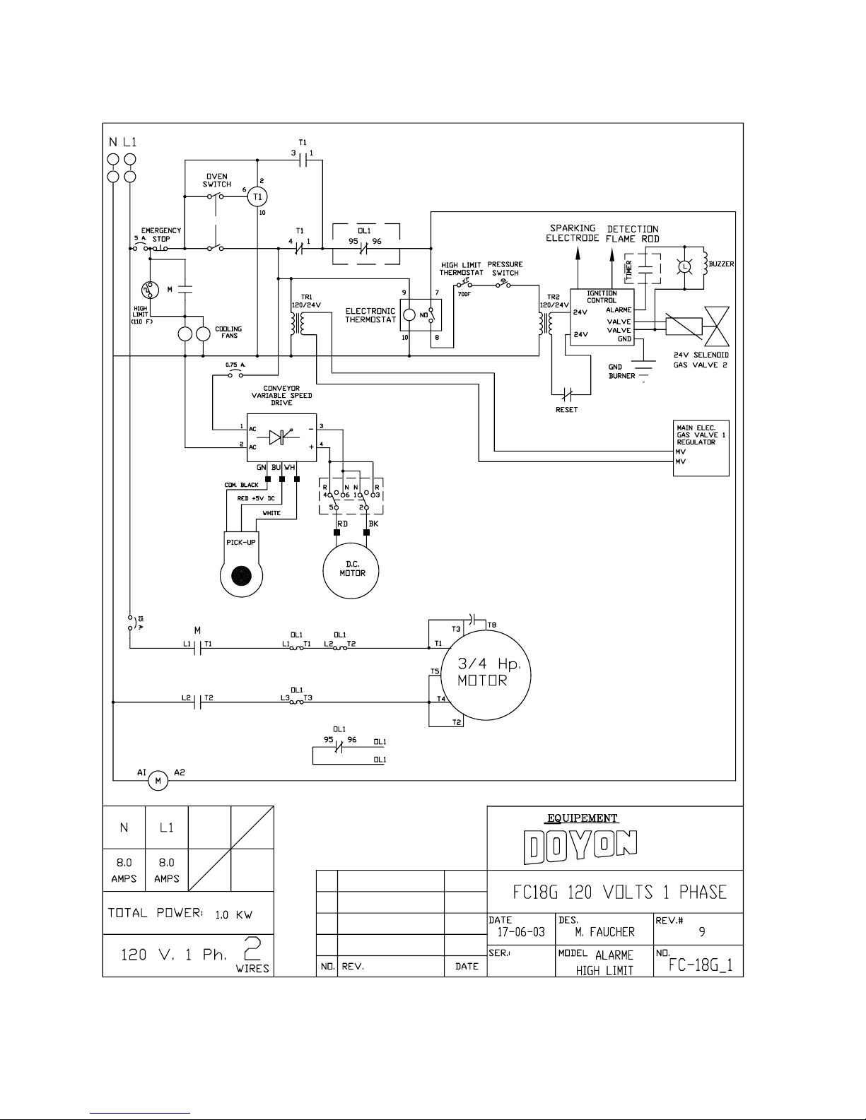
SECTION « G » ELECTRIC SCHEMATICS
FC18G 120V/1PH/60 Hz . . . . . . . . . . . . . . . . . . . . . . . . . . . . . . . . . . . . . . G1
FC18G 220V/1PH/50 Hz . . . . . . . . . . . . . . . . . . . . . . . . . . . . . . . . . . . . . . G2
FC18G 220V/1PH/60 Hz . . . . . . . . . . . . . . . . . . . . . . . . . . . . . . . . . . . . . . G3
FC2G 120V/1PH/60 Hz . . . . . . . . . . . . . . . . . . . . . . . . . . . . . . . . . . . . . . . G4
FC2G 220V/1PH/60 Hz . . . . . . . . . . . . . . . . . . . . . . . . . . . . . . . . . . . . . . . G5
Warranty . . . . . . . . . . . . . . . . . . . . . . . . . . . . . . . . . . . . . . . . . . . . . . . . . . .
CAUTION
In case of strong gas odours, shut off the gas input valve
and contact a specialised gas technician.
FCG-A.DOC Rev. 02-2003
Page 3

A-1
INTRODUCTION
The manufacturer suggests to read this manual carefully and to keep it for future reference.
This Jet Air gas fired oven is manufactured with first quality material by experienced technicians.
Proper installation and maintenance will guarantee a reliable service for years to come.
A nameplate fixed at the back of the oven specifies the model number, serial number, voltage,
amperage and frequency.
Drawings, electrical diagram and replacement part numbers are included in this manual. The
electrical diagram is affixed in the control panel under the hood of the oven.
ATTENTION
DOYON is not responsible for damages to the property or the equipment caused by
personnel who is not certified by known organisations. The customer is responsible for
finding qualified technicians in gas, electricity and plumbing for the installation of the
oven.
CONSTRUCTION
You just bought the most advanced gas fired oven in the world, "DOYON" technology at its best.
This gas fired oven is manufactured using the highest quality components and material.
The oven gives a perfect uniform baking with its unique Jet Air convection system. The DOYON
gas fired oven is designed with parts that are easy to find.
SHIPPING
For your safety, this equipment is verified by qualified technicians and carefully crated before
shipment. The freight company assumes full responsibility concerning the delivery in good condition
of the equipment in accepting to transport it.
IMPORTANT
RECEPTION OF THE MERCHANDISE
Take care to verify that the received equipment is not damaged before signing the delivery receipt. If
a damage or a lost part is noticed, write it clearly on the receipt. If it is noticed after the carrier left,
contact immediately the freight company in order that they do their inspection.
We do not assume the responsibility for damages or losses that may occur during transportation.
Page 4

A-2
INSTALLATION WARNINGS
The DOYON gas fired ovens are designed to be used with the gas specified on the descriptive
nameplate. Refer to National Fuel Gas Code, ANSI-Z223.1 and CAN/CGA.B149. Copies of these
are available at:
American Gas Association, 1515 Wilson Boulevard, Arlington, Virginia, 22209.
Canadian Gas Association, 55 rue Scarsdale, Don Mills, Ontario, Canada, M3B 2R3.
POWER FAILURE WARNING
WHEN YOU HAVE A POWER FAILURE, SHUT OFF THE OVEN POWER SWITCH TO
PROTECT THE ELECTRONICS COMPONENTS WHEN THE POWER COMES BACK.
FOR YOUR SAFETY
DO NOT STORE OR USE GASOLINE OR OTHER FLAMMABLE VAPOURS
AND LIQUIDS IN THE VICINITY OF THIS OR ANY APPLIANCE.
INSTALLATION AND SERVICE
WARNING
IMPROPER INSTALLATION, ADJUSTMENT, ALTERATION, SERVICE OR
MAINTENANCE CAN CAUSE PROPERTY DAMAGE, INJURY OR DEATH.
READ THE INSTALLATION, OPERATING AND MAINTENANCE INSTRUCTIONS
THOROUGHLY BEFORE INSTALLING OR SERVICING THIS EQUIPMENT.
Installation and service must be done by specialised technicians. Contact a certified gas technician,
electrician and plumber for set up.
The oven must be connected to the utility and electrically grounded in conformity to the effective
local regulations. If these are not established, the oven must be connected according to the
Canadian Electrical Code (CSA-C22.1-XX) or National Electrical Code (NFPA 70-XX). Refer to
last edition year for XX.
The ovens must be installed with proper ventilation like:
• Under a vent hood with outside air exit
• The connection of the exhaust pipe flue is not required.
Make sure that provision for adequate air supply is provided for the operation of the oven.
Do not permit fans to blow directly at the oven and whenever possible, avoid open windows
next to oven sides or back and wall type fans which create air cross currents the room.
Make sure that the adjustments mentioned in the "Installation" section are correctly
done prior to firing the oven or converting to a new gas.
CAUTION
Page 5

A-3
DISTANCES TO RESPECT
A) Back of the oven: 4 inches
B) Top of the oven: a clearance of 12 inches from above the top of the oven must exist to permit
adequate venting.
C) Floor: 4 inches minimum (legs)
D) Sides of the oven: No clearance required from the end of the conveyor. Do not install other
than easily removable equipment for service and maintenance.
Page 6
A-4
INSTALLATION
IN GENERAL
Take off the packaging material with care. Take off all the material used for packing and accessories.
Each unit is set up to be used with the type of gas and electrical supply specified on the name plate
fixed at the back of the oven.
The installation must be conform with National fuel gas code ANSI Z223.1 and CAN/CGA-B149,
Gas installation Code and local Codes where applicable.
The oven's combustion system consists of a very safe gas burner certified in accordance to the
American Gas Association Standard in USA and with the Canadian Gas Association in Canada.
1. To the certified gas technician.
The burner installed on DOYON gas fired ovens is set up and adjusted at the plant for a first
class operation. It is nevertheless necessary to verify on site the pressure at the burner input.
The following table indicates the pressures that must be set up to remain conform to the AGA
standards or CGA.
FC2G
GAS TYPE ALTITUDE
(FT)
Propane 0-2000 115,000 11,0 7,5 30
Propane 2000-4500 115,000 11,0 7,5 30
Natural 0-2000 115,000 7,0 3,4 9
Natural 2000-4500 115,000 7,0 3,4 9
INPUT
(BTUH)
REGULATOR
INPUT
PRESSURE
(Water column
inches)
BURNER
INPUT
PRESSURE
(Water column
inches)
BURNER
ORIFICE SIZE
(DMS)
FC18G
GAS TYPE ALTITUDE
(FT)
INPUT
(BTUH)
REGULATOR
INPUT
PRESSURE
(Water column
inches)
BURNER
INPUT
PRESSURE
(Water column
inches)
BURNER
ORIFICE SIZE
(DMS)
Propane 0-2000 52,000 11,0 7,5 44
Propane 2000-4500 52,000 11,0 7,5 44
Natural 0-2000 52,000 7,0 3,5 29
Natural 2000-4500 52,000 7,0 3,5 29
The burner used is adjusted for use with the gas indicated on the nameplate. It is
nevertheless possible to convert the burner to another gas by doing the modifications
indicated in the CONVERSION PROCEDURE provided with the oven. These
modifications must be done carefully and completely under the company's instruction
to remain conform to A.G.A. or C.G.A standards. Refer to Doyon Equipment to get
the right
CONVERSION KIT.
Page 7

A-5
The installation must be made with a connector that meets with the standard for connectors movable
gas appliances ANSI Z21.69 and a Quick-disconnect device that complies with the standard for
Quick-disconnect devices for use with gas fuel ANSI Z21.41 and addenda Z21.41a and Z21.41b. It
must also be installed with restraining (like a chain) to guard against transmission of strain to the
connector. The pipe fittings compound must be certified for gas.
The customer must install a manual shut off valve at the end of the gas supply pipe near the burner
which is approved by the American Gas Association Standard in Canada with the Canadian Gas
Association.
Clean the air contained in the gas supply pipe at the installation to insure a successful firing on the
first try. The gas pipe sealing compound tightness must be verified using a solution of water and
soap prior to firing the unit.
ATTENTION
Make sure not to obstruct the overpressure opening on the gas regulator.
NOTE: If there's any modification done to the system or change of the type of gas used,
make sure that the regulator pressure of the burner is adjusted as recommended in this
manual.
2. To the electrician.
Electrical supply installation must be in accordance with the electrical rating on the nameplate.
• Check if the rotation of the motor is in accordance with the arrow on top of each unit.
If NOT
If the power supply is 3 phases and the unit is not connected in the right phase
sequence, the fan motor will turn the wrong way. This will affect the baking quality.
Turn the power "OFF" and change the phase sequence.
WARNING
The electrician must make sure that the supply cable does not come in contact with the
oven top which becomes hot.
Page 8

A-6
OPERATION / INSTRUCTION
1. Turn the switch to the position "ON".
2. Adjust the thermostat at the desired temperature (see THERMOSTAT INSTRUCTIONS below).
3. Adjust baking time according to your product. Use the up and down arrows on the speed control
to set your baking time.
(see suggestions in the tables next page.)
N.B. The thermostat display must be "ON" (If not, press the breaker on the front)
4. Heat the unit until you reach the baking temperature.
When the desired temperature is reached, the red light ON goes out on the thermostat.
• If the red light on the front control panel is "ON" and the alarm buzzer rings, the oven does not
produce heat. To start it over, press the red button on the front control panel for 2 seconds. The
burner will start up (you can hear it). You can repeat this operation three times. If it does not
start up again, contact our company or a certified gas technician.
5 Place your products on the conveyor.
We recommend to use perforated pan or pizza screen.
6 To stop the oven, just turn the selector switch to "OFF" position. If the control compartment is too
hot, the cooling fan will run until the temperature drops.
THERMOSTAT INSTRUCTIONS
To obtain a very good thermal stability, we use a digital temperature controller with thermocouple.
The Omron E5CS thermostat controls the heat at the SP (set point).
The temperature of the oven is always shown on the display of the thermostat and an arrow indicates
if the temperature is over or below the SP. When the green light is lit, it indicates that the temperature
is at the SP ± 1 %.
To adjust the SP value, you just have to press the key on the left and use the up and down keys to set
temperature and alarm value. Press the left key to return to run mode.
Page 9
A-7
COOKING TIME AND TEMPERATURE RECOMMENDATION
REGULAR PIZZA BAKING TIME
Temperature Pizza Approximate baking time
5350 F PEPPERONI 5.00 minutes
5350 F ALL DRESS 5.20 minutes
515° F EXTRA TOPPING 6.00 minutes
490° F SPECIAL HOUSE 7.00 minutes
PIZZA PAN BAKING TIME
Temperature Pan pizza Approximate baking time
4800 F ALL DRESS 7.20 minutes
540°F ALL DRESS 5.00 minutes
IMPORTANT: You must adjust your baking time according to your own recipes. We
recommend that you conduct a few baking tests at the beginning and note your baking time
for future reference.
Page 10
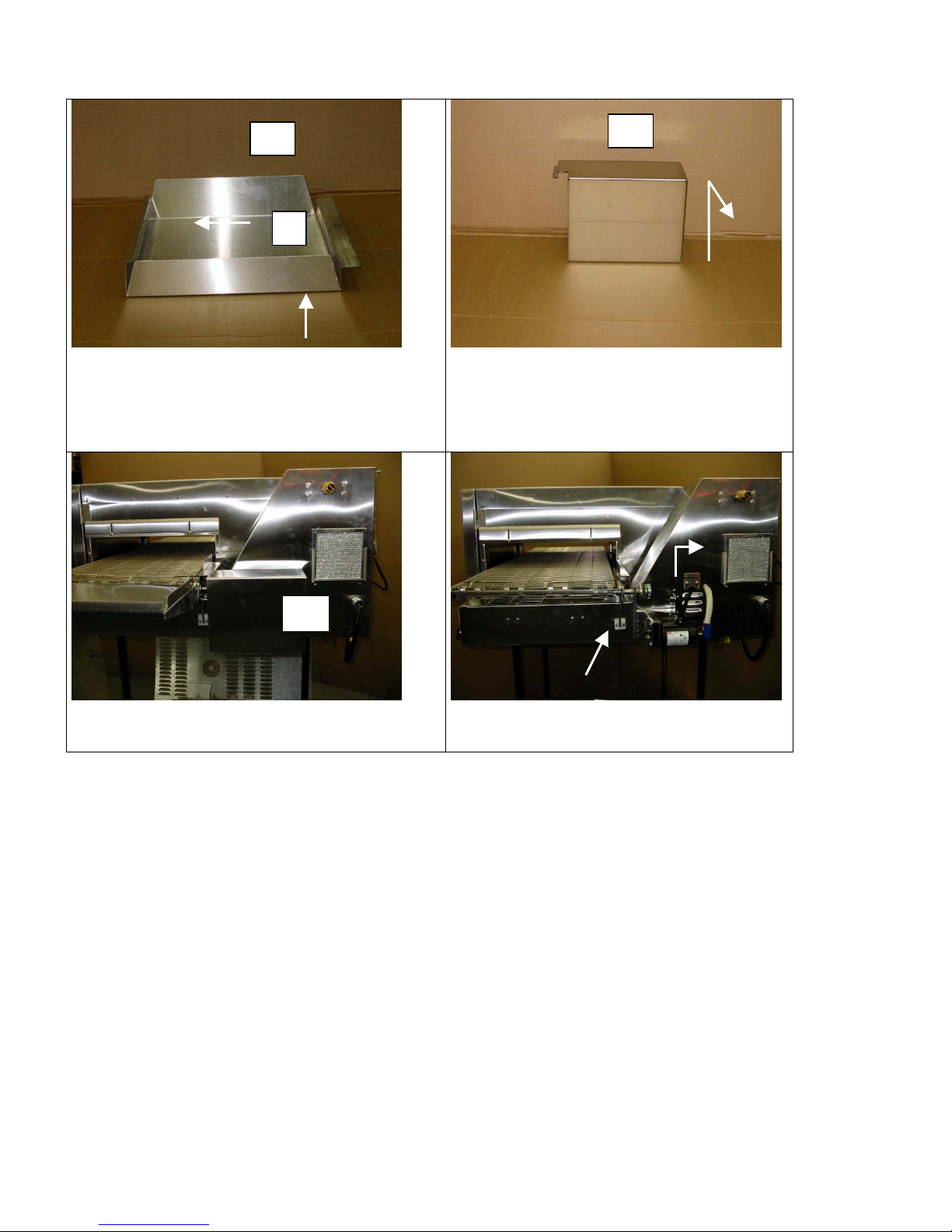
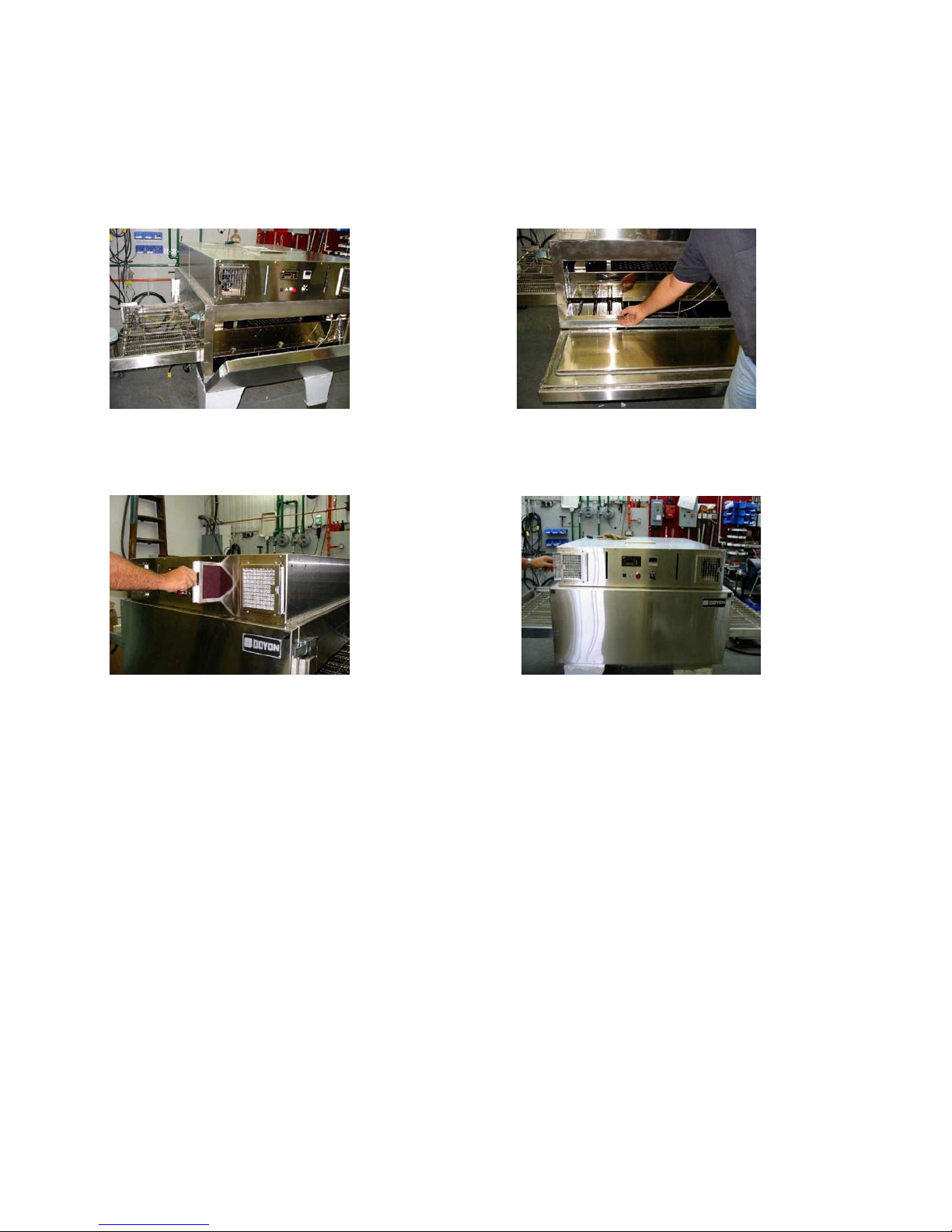
A-8
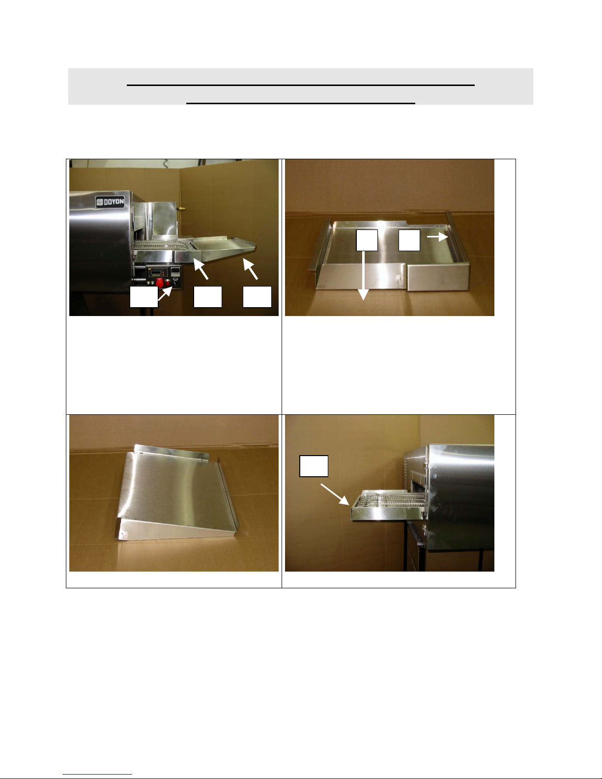
INSTRUCTIONS TO REMOVE THE CONVEYOR
AND CLEAN THE OVEN FC18G
12
A C B
1. Turn the power off ( A ).
♦ Remove the extended shelf ( B ).
♦ Remove the right tray ( C ).
3. Right tray ( C ).
♦ To remove the tray :
♦ Push ( 1 ) to the left (5mm),then lift
(10mm), then pull to the right ( 3cm )
♦ Pull the tray in the same direction as
indicated in ( 2 ) above.
D
2. Extended shelf ( B ). 4. Left tray ( D ).
Page 11
A-9
D
1
5. Left tray ( D ).
♦ To remove the tray :
♦ Push ( 1 ) to the right (5mm),then lift
(10mm), then pull to the left.
E
7. Remove gearbox cover ( E ).
♦ Lift ( 2cm ).
♦ Pull away from oven.
E
6. Remove gearbox cover ( E ). 8. Remove rubber strap.
♦ Lift gearbox to remove the chain.
Page 12
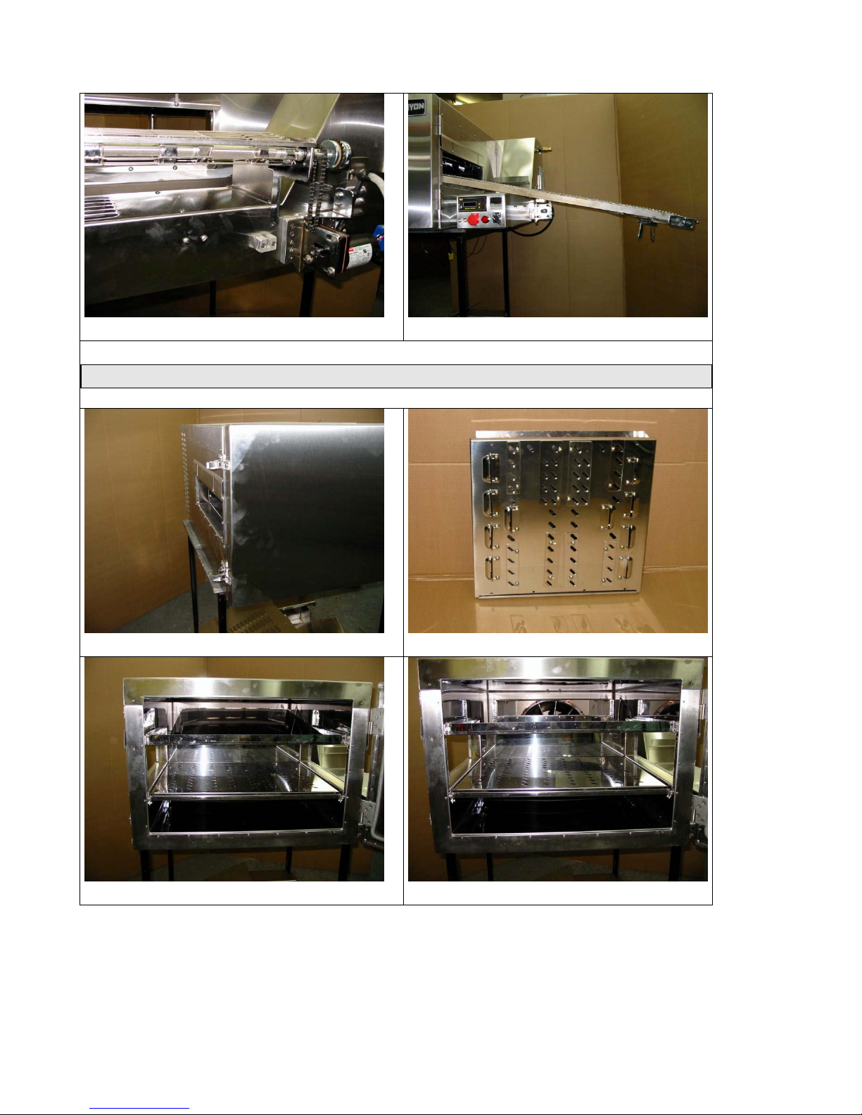
A-10
9. Lift conveyor ( 2cm ) and pull it out. 10. Remove conveyor completely.
INTERIOR SECTION
11. Open the door. 13. Top heat diffuser.
12. Remove the heat diffusers. 14. Interior without top heat diffuser.
Page 13
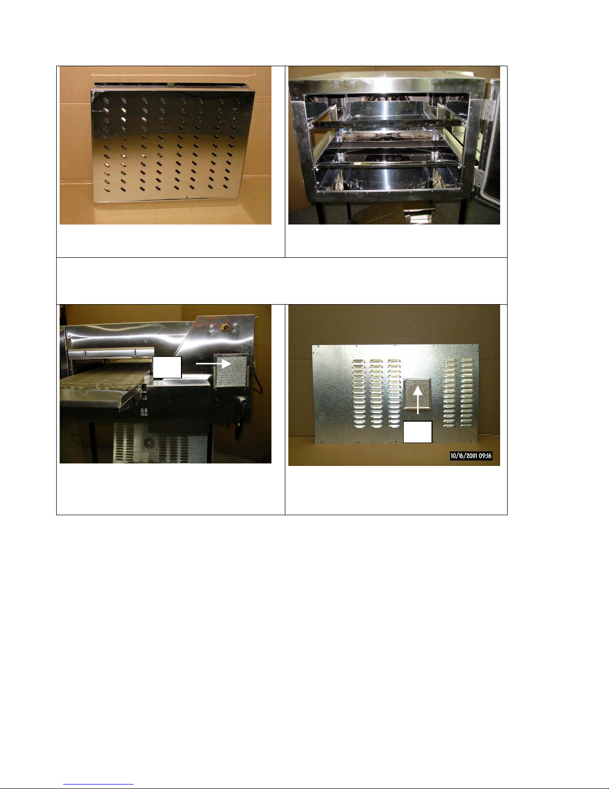
A-11
15. Remove bottom heat diffuser. 16. Interior without top and bottom
heat diffuser.
FILTERS
F
17. The filters ( F,G ) must be cleaned
regularly, to maintain a good
ventilation.
G
18. The filters may be cleaned with
water and dishwashing liquid or
replaced by a new filter.
Page 14
A-12
INSTRUCTIONS TO REMOVE THE CONVEYOR
AND CLEAN THE OVEN FC2G
NOTE: In order to remove the conveyor, it is necessary to be two people.
1- Place the oven main switch [A] to the position "OFF" (see drawing next pages).
2- Make sure that the oven has cooled down completely.
3- Disconnect the yellow plug of the conveyor motor [B] (unscrew the plug).
A
B
4- Remove the two crumb tray located under the conveyor [C] (lift it approximately 1/2
inch (1cm) and remove).
C C
5- Take out the screws which hold the two finishing plates on each side of the conveyor
[D] and remove the finishing plate. [E]
6
D
E
6- To take out the conveyor, it takes two people, one at each end. The person who is at
the opposite side of the gear motor of the conveyor raises it 1 inch (2 cm) and pushes
it towards the front. When the end of the conveyor is inside the oven, it is preferable
that the same two people place themselves on each side of the conveyor and continue
to pull with precaution to take out the conveyor completely.
7- To re-install the conveyor, repeat the instructions above in reverse.
Note: It is possible to reverse the conveyor. When you are ready to re-install, just enter it at
the opposite side of the oven.
6
Page 15
A-13
INTERIOR:
1-Remove the conveyor (see PAGE A12).
2-Open the door. 3-Remove the 3 bottom deflector panels.
4-Clean the interior of the oven, the 3 bottom deflector panels and the conveyor with oven cleaner
(EASY OFF or MR. MUSCLES).
5-Clean the air filter located on the front of the oven. Use water and soap.
EXTERIOR:
Use stainless steel cleaner.
We recommend and sell Product # NES 201.
Page 16
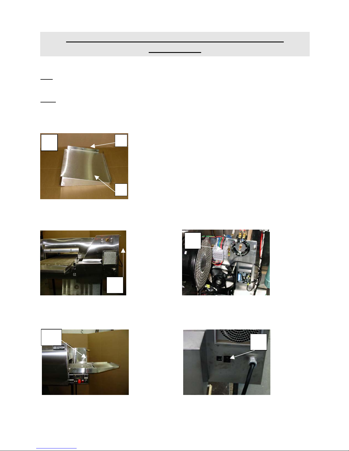
A-14
INSTRUCTIONS TO REVERSE DIRECTION OF THE
CONVEYOR
FC2
To reverse the direction of the conveyor on FC2 oven, follow the instructions at page A12.
FC18
When you reverse the conveyor direction, you have to install the extension shelf on the other side of
the conveyor (see picture A). Unscrew the pizza stopper [1] and screw to the other side of the
extension [2].
A 1
2
To reverse the direction of the conveyor, open the back panel of the oven. (picture B) Disconnect the
red and black wirse of the conveyor motor on the gray terminal block and invert the two wires.
(picture C) The conveyor should run in the other direction.
C
B
To reverse on some models with the optional directional switch, change the position of the switch
located beside (picture D and E) the conveyor motor from position I to II.
WARNING: Shut off the main power switch of the oven before reversing the conveyor.
D
E
Page 17
A-15
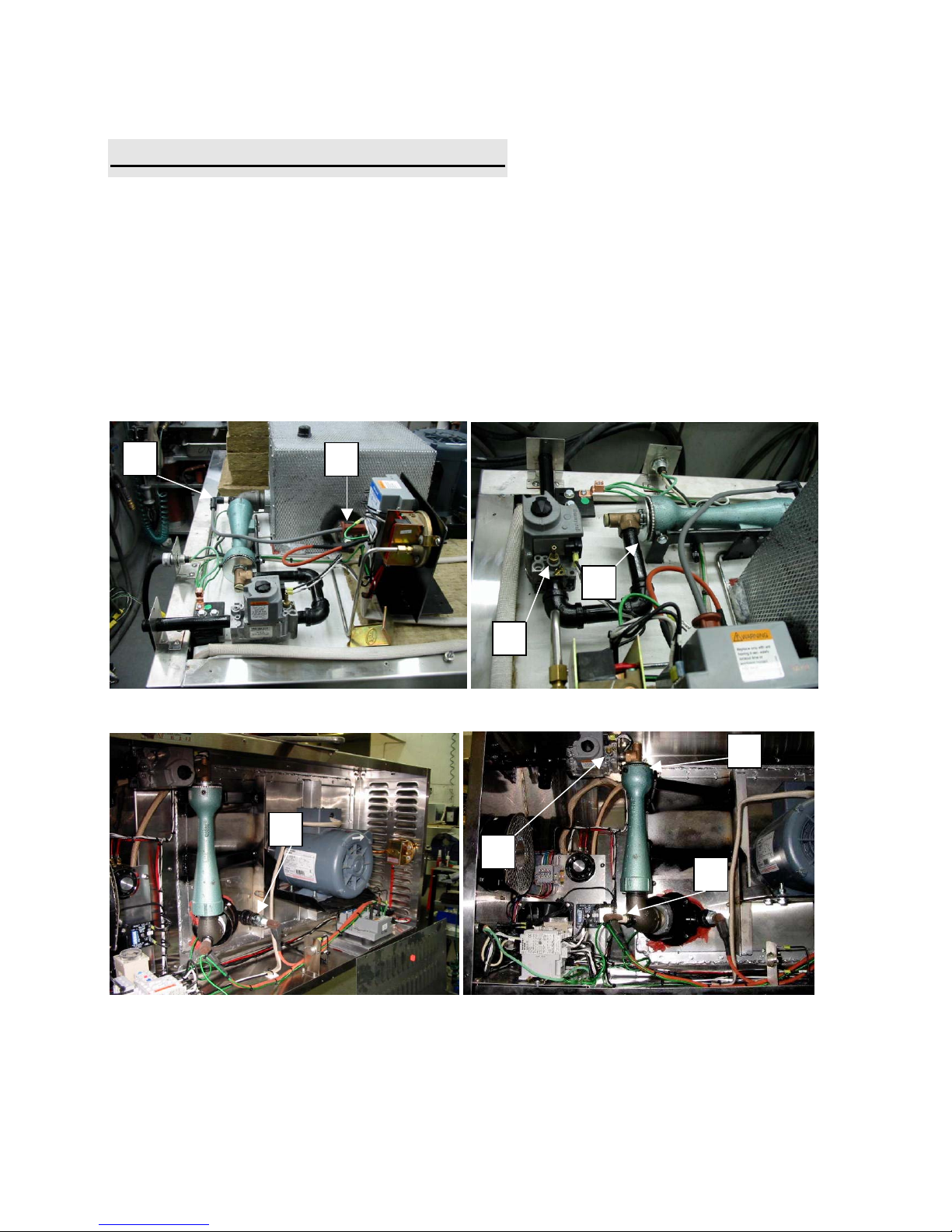
MAINTENANCE OF THE BURNER
Once a year, you should ask a certified technician to make a tune up.
Make sure everything works properly, verify and clean especially:
1 The gas mixer air inlet
2 The spark rod and porcelain insulators
3 The flame detection rod
4 Verify the burner input pressure
5 Verify every adjustments (Ignition rod gap, microamps on the detection and air inlet opening)
6 Clean every moving pieces
FC2G
2
FC18G
3
1
4
1
3
4
2
Page 18
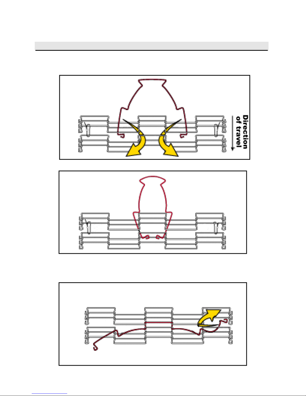
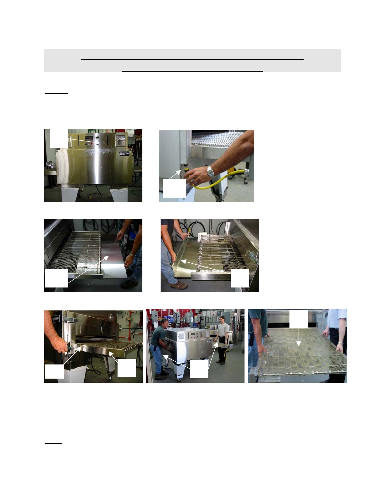
A-16
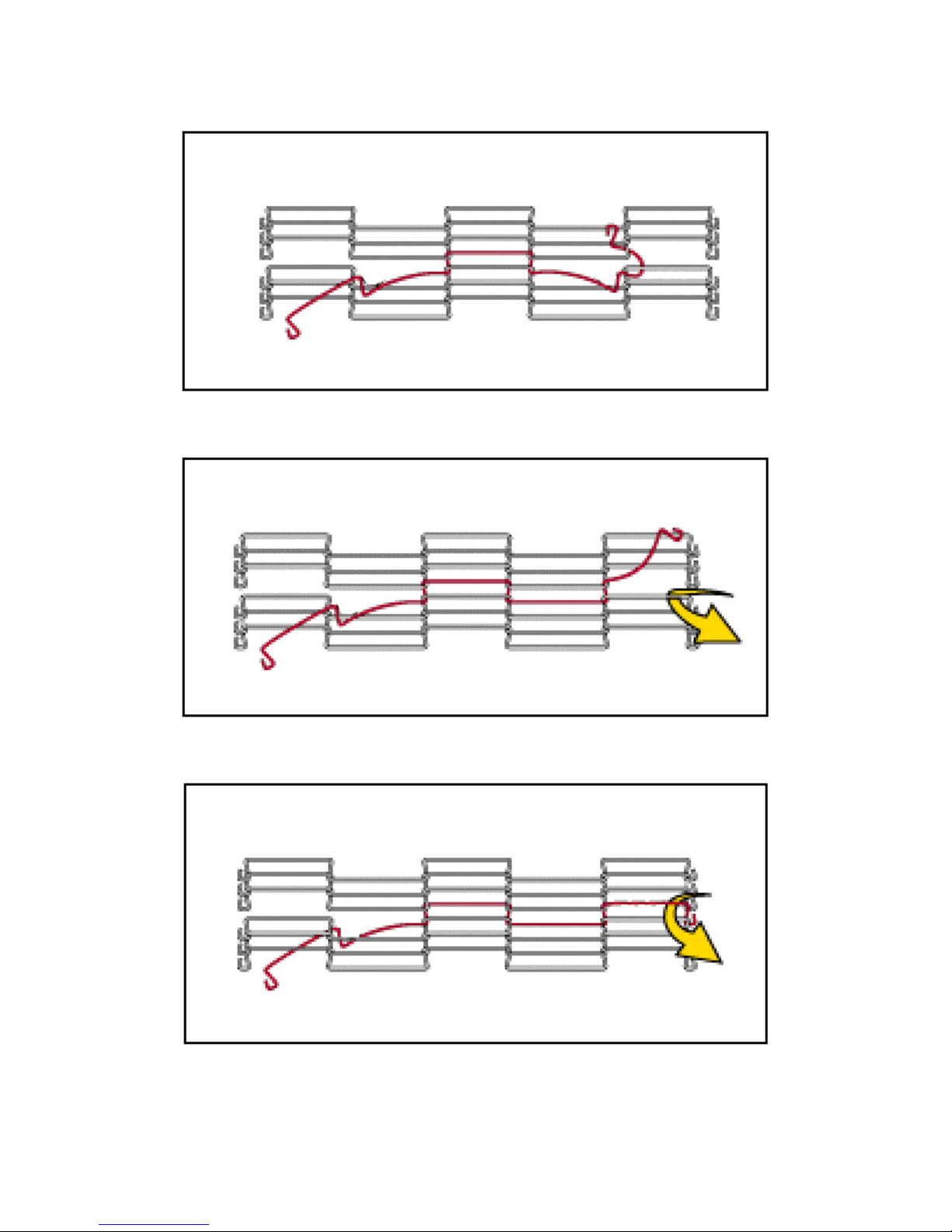
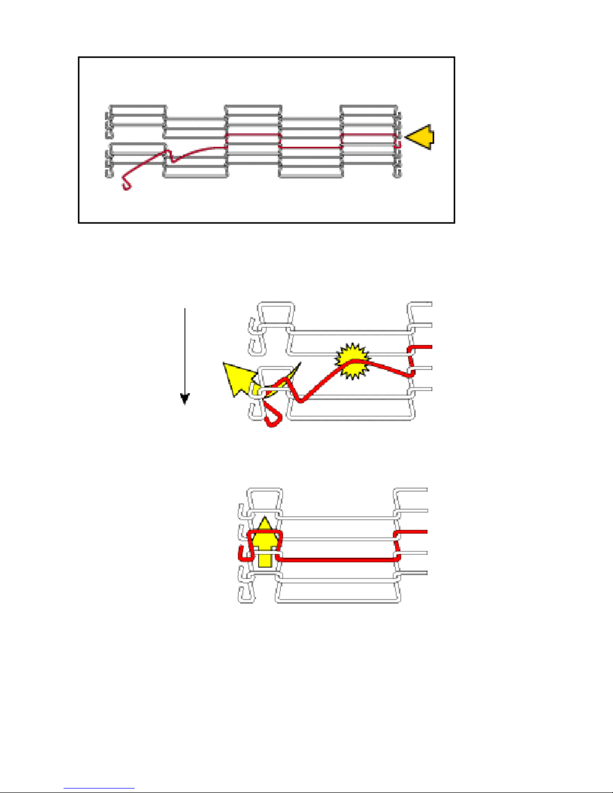
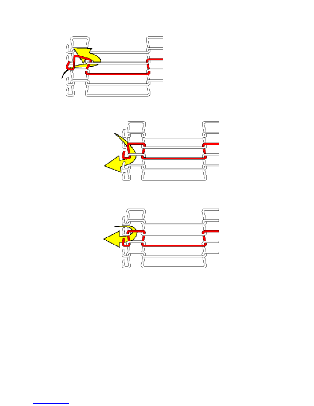
INSTRUCTIONS TO REMOVE THE BELT ON THE CONVEYOR
Page 19
A-17
Page 20
A-18
Page 21
A-19
Page 22

A-20
TROUBLESHOOTING
BEFORE CALLING FOR SERVICE
ANSWERS TO MOST FREQUENT QUESTIONS
Questions Solutions
The oven is "ON", but does not function.
The fan runs but the oven does not heat.
The red light on the front control panel is on
and the alarm ring.
The oven heat too much or does not produce
heat enough.
The conveyor chain is not tight enough.
• Check the main breaker (the one on the
building panel) and also the breaker located
at the front of the oven (5 amps).
On FC18G oven, check if the emergency
stop switch located at the front of the oven is
pulled out.
• Check if the thermostat is adjusted high
enough to fire the oven.
• Check the main gas valve.
• To start it over, press the red button on the
front control panel for 2 seconds. The burner
will start up (you can hear it). You can
repeat this operation three times. If it does
not start up again, contact our company or a
certified gas technician.
Measure the temperature with an oven
thermometer and compare it with the
temperature indicated on the thermostat.
To tighten:
The conveyor does not turn.
• Take off the protector at the end of the speed
control located on the sides of the conveyor.
With a 7/16" key, lightly unscrew the 2
screws having an adjustment on each side;
• Tighten the belt of the conveyor and the
screws;
• Put back the protectors.
• Check the 0.75 amps breaker on the front
for FC2G or on the side for FC18G of the
oven.
• If the breaker is "tripped", check if the
conveyor is free from any obstructions
before resetting the breaker.
• Check the conveyor main shaft if the
security clutch is not slipping.
Page 23

A-21
FOR MORE INFORMATION,
PLEASE CONTACT OUR OFFICE :
DOYON EQUIPMENT INC.
1255, rue Principale
Linière, Qc, Canada G0M 1J0
Tel. : 1 (418) 685-3431
Canada : 1 (800) 463-1636
U.S. : 1 (800) 463-4273
FAX : 1 (418) 685-3948
Internet: http://www.doyon.qc.ca
E-Mail : doyon@doyon.qc.ca
Page 24

SECTION
B
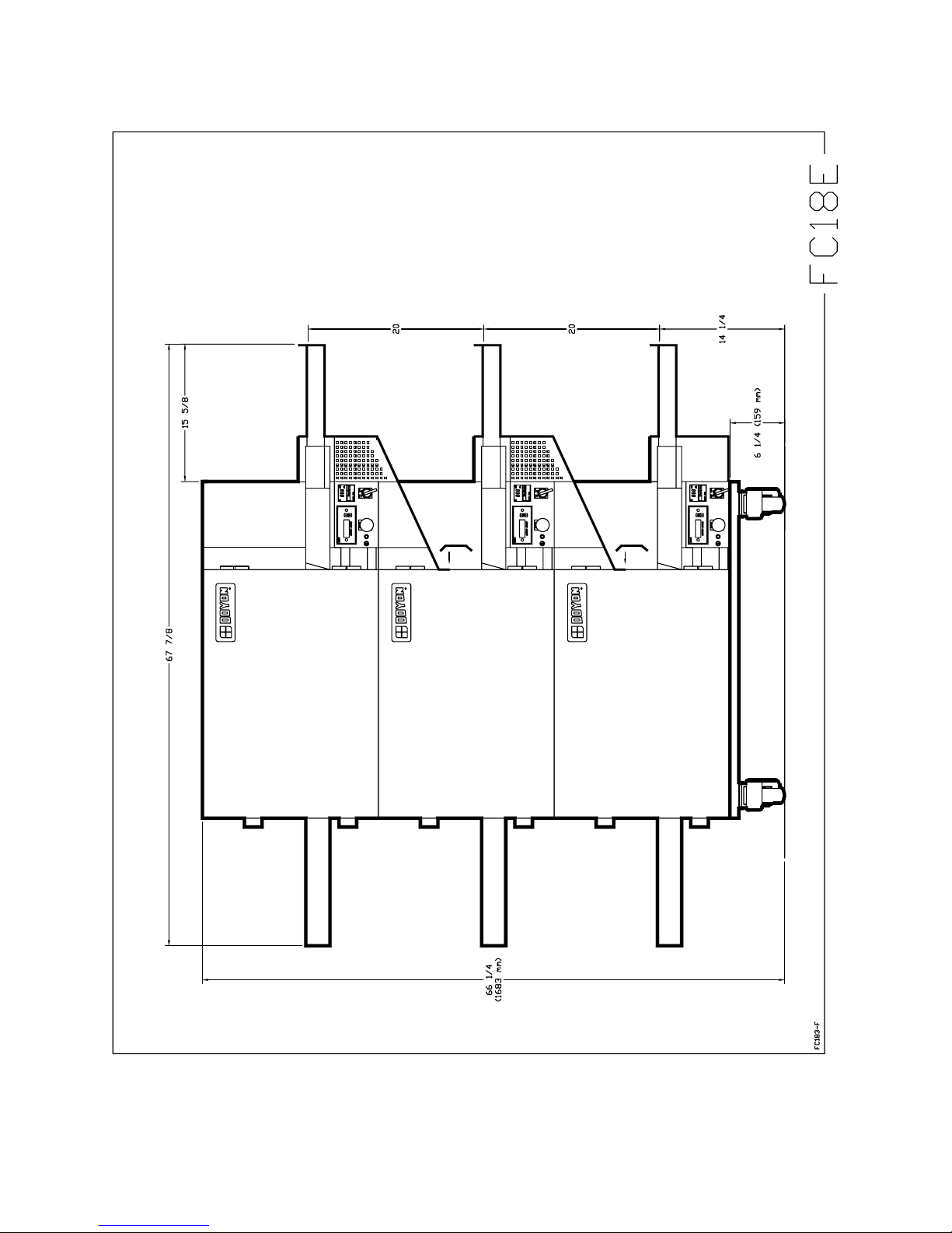
DIMENSIONS
Page 25

B-1
Page 26

B-2
Page 27
B-3
Page 28

B-4
Page 29

B-5
Page 30

B-6
Page 31

B-7
Page 32

B-8
Page 33

SECTION
C
BURNER AJUSTMENT
Page 34

C-1
Page 35

C-2
Page 36

C-3
Page 37

C-4
Page 38

SECTION
D
HEAT DIFFUSER ADJUSTMENT
Page 39

D-1
Page 40

D-2
Page 41

D-3
Page 42

D-4
Page 43

D-5
Page 44

SECTION
E
COMPONENT PARTS
Page 45

E-1
Page 46

E-2
Item Part Number Description Quantity
1 ELM960 CONVEYOR CONTROL MOTOR DART 1
2 ELB096 5A BREAKER 1
3 ELB099 15A BREAKER 1
4 ELP991 EMERGENCY SWITCH KNOB 1
AND ELI575 CONTACT BLOCK 1NC 1
5 ELI550 MAIN SWITCH (SELECTOR) 1
AND ELI555 CONTACT BLOCK 1NO 2
AND ELI556 ON - OFF PLATE 1
6 ELT515 OMRON THERMOSTAT E5CS 1
AND ELT532 THERMOCOUPLE TYPE K 1
7 ELL780 HIGHLITED PUSH BOTTON SOCKET 1
AND ELL640 MINI LAMP (24V) 1
AND ELL755 PUSH BOTTON SOCKET (N.C.) 1
Model : FC-18-G View : FRONT
Page 47

E-3
Page 48

E-4
Item Part Number Description Quantity
1 ELM940 CONVEYOR MOTOR GEARBOX 1
2 ELM961 PULSE GENERATOR, DART 1
3 ELB089 .75 AMP BREAKER 1
4 50093010 SPROCKET CLUTCH ASSEMBLY 1
5 ELI638 CONVEYOR SWITCH 1
Model : FC-18-G View : SIDE
Page 49

E-5
Page 50

E-6
Item Part Number Description Quantity
1 ELM762 MOTOR BLOWER 120V 250 C.F.M. 1
2 ELT680 THERMOSTAT 700°F 1
AND ELT681 THERMOSTAT KNOB 700°F 1
AND ELT620 THERMOSTAT BEZEL 1
3 GAM200 ATMOSPHERIC MIXER 1
4 GAC230 HONEYWELL GAS VALVE #VR8205A2008B 1
AND GAC241N NATURAL GAS PRESSURE REGULATOR 1
OR GAC241P PROPANE GAS PRESSURE REGULATOR 1
5 ELM800M MOTOR .75HP 1PH 115/208-230V 60Hz/50Hz MAGNATEK 1
OR ELM820M MOTOR 3/4HP 3PH 208/230/460V 60Hz/50Hz MAGNATEK 1
AND STR400 SHAFT EXTENSION 1
AND STF425 MOTOR COOLING FAN 1
6 GAP300 PRESSURE SWITCH 1
7 QUC900 CONVEYOR CHAIN 18" WIDE 1
8 GAT100 TRANSFORMER 120/25V 20VA. 1
9 GAB500 ELECTRONIC CONTROL WITH ALARM CONTACT 1
10 GAD200 FLAME DETECTION ROD#11ZK3F2127 1
11 ELM760 MOTOR BLOWER 1
12 (PAN 120V 1Ph (SEE 120V SIMP. FC-18-G) 1
OR (PAN 120V 1Ph (SEE 120V SIMP. FC-18-G) 1
13 ELS940 BUZZER (24V) 1
14 ELM735 SOLID STATE TIMER ICM FOR CH460,JAOP3-G, FC2-G
1
AND E233
15 ELT507 HIGH TEMPERATURE LIMIT SWITCH 110°F 1
15 ELT507 HIGH LIMIT TEMPERATURE 110°F 1
16 ELB073 TERMINAL BLOCK 30A 5
17 ELT725 TRANSFORMER 240/120 250VA (FOR 220V 50HZ MODEL
1
ONLY)
18 GAD190 IGNITION ROD 1
Model : FC-18-G View : BACK
Page 51

E-7
Page 52

E-8
Item Part Number Description Quantity
1 ELM961 PULSE GENERATOR, DART 1
2 ELM940 CONVEYOR MOTOR GEARBOX 1
3 ELM760 MOTOR BLOWER 3
4 ELB089 .75 AMP BREAKER 1
5 ELB096 5A BREAKER 1
6 ELM960 CONVEYOR CONTROL MOTOR DART 1
7 ELT515 OMRON THERMOSTAT E5CS 1
8 ELI550 MAIN SWITCH (SELECTOR) 1
AND ELI555 CONTACT BLOCK 1NO 2
AND ELI556 ON - OFF PLATE 1
9 ELL780 HIGHLITED PUSH BOTTON SOCKET 1
AND ELL755 PUSH BOTTON SOCKET (N.C.) 1
AND ELL640 MINI LAMP (24V) 1
10 QUF100 FILTER 2
11 50093010 SPROCKET CLUTCH ASSEMBLY 1
Model : FC-2-G View : FRONT
Page 53

E-9
Page 54

E-10
Item Part Number Description Quantity
1 ELM800ML MOTOR 1 PH. 3/4 HP.MAGNETEK WITH 6 1/4 INCH
1
SHAFT.
2 GAB500 ELECTRONIC CONTROL WITH ALARM CONTACT 1
3 GAP300 PRESSURE SWITCH 1
4 GAC230 HONEYWELL GAS VALVE #VR8205A2008B 1
AND GAC241N NATURAL GAS PRESSURE REGULATOR 1
OR GAC241P PROPANE GAS PRESSURE REGULATOR 1
5 GAM200 ATMOSPHERIC MIXER 1
6 GAD200 FLAME DETECTION ROD#11ZK3F2127 1
7 QUC910 CONVEYOR CHAIN 36" WIDE 1
8 P120SFCG PAN 120V 1PH (SEE 120V SIMP. FC-2-G) 1
OR ((PAN 220V 1Ph (SEE 220V SIMP. FC-2-G)) 1
9 GAD190 IGNITION ROD 1
Model : FC-2-G View : TOP
Page 55

SECTION
F
CONTROL PANELS
Page 56

F-1
Page 57

F-2
Item Part Number Description Quantity
1 ELC510 MOTOR CONTACTOR 2HP (SPRECHER) 1
AND ELC520 CONTACTOR COIL (ONLY) (SPRECHER)
OR ELC496 MOTOR CONTACTOR 2HP (TELEMEC.) 1
AND ELC505B CONTACTOR COIL (ONLY) (TELEMEC.)
2 ELO220 OVERLOAD RELAY BASE 1
AND ELO210 OVERLOAD 6 - 9.5 Amps. 1
3 ELM720 OMRON CONTROL TIMER (11 PIN) H3CR 1
AND ELM729 11 PIN BASE 1
Model : P120FC1G (FC18G) View : INSIDE (See BACK OVEN)
Page 58

F-3
Page 59

F-4
Item Part Number Description Quantity
1 GAT100 TRANSFORMER 120/25V 20VA. 1
2 ELS940 BUZZER (24V) 1
3 ELF975 FUSE HOLDER 30A 250V 1P 1
4 ELF830 FUSE 15A 250V 1
5 ELC510 MOTOR CONTACTOR 2HP 1
AND ELC950 SPRECHER AUXILIARY CONTACT BLOCK 1
6 ELO220 OVERLOAD RELAY BASE 1
AND ELO210 OVERLOAD 6 - 9.5 Amps. 1
7 ELM720 OMRON CONTROL TIMER (11 PIN) H3CR 1
AND ELM729 11 PIN BASE 1
8 ELT507 HIGH TEMPERATURE LIMIT SWITCH 110°F 1
8 ELT507 HIGH LIMIT TEMPERATURE 110°F 1
9 ELT680 THERMOSTAT 700°F 1
AND ELT681 THERMOSTAT KNOB 700°F 1
AND ELT620 THERMOSTAT BEZEL 1
10 ELM735 SOLID STATE TIMER ICM FOR CH460,JAOP3-G, FC2-G
1
AND E233
Model : FC-2-G 120V 1PH (P120SFC2G) View : INSIDE (See OVEN TOP)
Page 60

F-5
Page 61

F-6
Item Part Number Description Quantity
1 GAT100 TRANSFORMER 120/25V 20VA. 1
2 ELS940 BUZZER (24V) 1
3 ELF975 FUSE HOLDER 30A 250V 1P 1
4 ELF830 FUSE 15A 250V 1
5 ELC510 MOTOR CONTACTOR 2HP ((SPRECHER) 1
AND ELC950 SPRECHER AUXILIARY CONTACT BLOCK ((SPRECHER) 1
6 ELO220 OVERLOAD RELAY BASE ((SPRECHER) 1
7 ELM720 OMRON CONTROL TIMER (11 PIN) H3CR 1
AND ELM729 11 PIN BASE 1
8 ELO205 OVERLOAD 3.8 - 6 Amps. ((SPRECHER) 1
9 ELT507 HIGH TEMPERATURE LIMIT SWITCH 110°F 1
9 ELT507 HIGH LIMIT TEMPERATURE 110°F 1
10 ELT680 THERMOSTAT 700°F 1
AND ELT681 THERMOSTAT KNOB 700°F 1
AND ELT620 THERMOSTAT BEZEL 1
11 ELM735 SOLID STATE TIMER ICM FOR CH460,JAOP3-G, FC2-G
1
AND E233
12 ELT725 TRANSFORMER 240/120 250VA 1
Model : 220V 1PH FC-2-G (P220SFC2G) View : INSIDE (See OVEN TOP)
Page 62

SECTION
G
ELECTRIC SCHEMATICS
Page 63
G-1
Page 64

G-2
Page 65

G-3
Page 66

G-4
Page 67

G-5
Page 68

40
LIMITED WARRANTY
(Continental United States Of America And Canada Only)
Doyon Equipment Inc. guarantees to the original purchaser only that
its product are free of defects in material and workmanship, under
normal use.
This warranty does not cover any light bulbs, thermostat calibration or
defects due to or resulting from handling, abuse, misuse, nor shall it
extend to any unit from which the serial number has been removed or
altered, or modifications made by unauthorised service personnel or
damage by flood, fire or other acts of God. Nor will this warranty
apply as regards to the immersion element damaged by hard water.
The extent of the manufacturer’s obligation under this warranty shall
be limited to the replacement or repair of defective parts within the
warranty period. The decision of the acceptance of the warranty will
be made by Doyon Equipment service department, which decision
will be final.
The purchaser is responsible for having the equipment properly
installed, operated under normal conditions with proper supervision
and to perform periodic preventive maintenance.
If any parts are proven defective during the period of one year from
date of purchase, Doyon Equipment Inc. hereby guarantees to replace,
without charge, F.O.B. Linière, Quebec, Canada, such part or parts.
Doyon Equipment Inc will pay the reasonable labour charges in
connection with the replacement parts occurring within one year from
purchase date. Travel over 50 miles, holiday or overtime charges are
not covered. After one year from purchase date, all labour and
transportation charges in connection with replacement parts will be the
purchaser’s responsibility.
Doyon Equipment Inc. does hereby exclude and shall not be liable to
purchaser for any consequential or incidental damages including, but
not limited to, damages to property, damages for loss of use, loss of
time, loss of profits or income, resulting from any breach or warranty.
In no case, shall this warranty apply outside Canada and continental
United States unless the purchaser has a written agreement from
Doyon Equipment Inc.
 Loading...