

Page 1

DRIP1TLO, E236TLO, E336TLO & E460TLO
IMPORTANT SAFETY INSTRUCTIONS
SAVE THESE INSTRUCTIONS
DANGER
TO REDUCE THE RISK OF FIRE OR ELECTRIC SHOCK, CAREFULLY FOLLOW
THESE INSTRUCTIONS.
TABLE OF CONTENTS
SECTION « A » DESCRIPTION PAGE
Introduction . . . . . . . . . . . . . . . . . . . . . . . . . . . . . . . . . . . . . . . . . . . . . . . . . A1
Construction . . . . . . . . . . . . . . . . . . . . . . . . . . . . . . . . . . . . . . . . . . . . . . . . A2
Shipping . . . . . . . . . . . . . . . . . . . . . . . . . . . . . . . . . . . . . . . . . . . . . . . . . . . . A2
Warnings . . . . . . . . . . . . . . . . . . . . . . . . . . . . . . . . . . . . . . . . . . . . . . . . . . . A3
Distances to respect . . . . . . . . . . . . . . . . . . . . . . . . . . . . . . . . . . . . . . . . . . . A4
Installation . . . . . . . . . . . . . . . . . . . . . . . . . . . . . . . . . . . . . . . . . . . . . . . . . . A4
Operation of the digital control . . . . . . . . . . . . . . . . . . . . . . . . . . . . . . . . . . A5
Troubleshooting . . . . . . . . . . . . . . . . . . . . . . . . . . . . . . . . . . . . . . . . . . . . . A6
Maintenance and cleaning . . . . . . . . . . . . . . . . . . . . . . . . . . . . . . . . . . . . . . A7
For more information, please contact our office: . . . . . . . . . . . . . . . . . . . . A9
SECTION « B » DIMENSIONS
DRIP1 TLO. . . . . . . . . . . . . . . . . . . . . . . . . . . . . . . . . . . . . . . . . . . . . . . . . B1
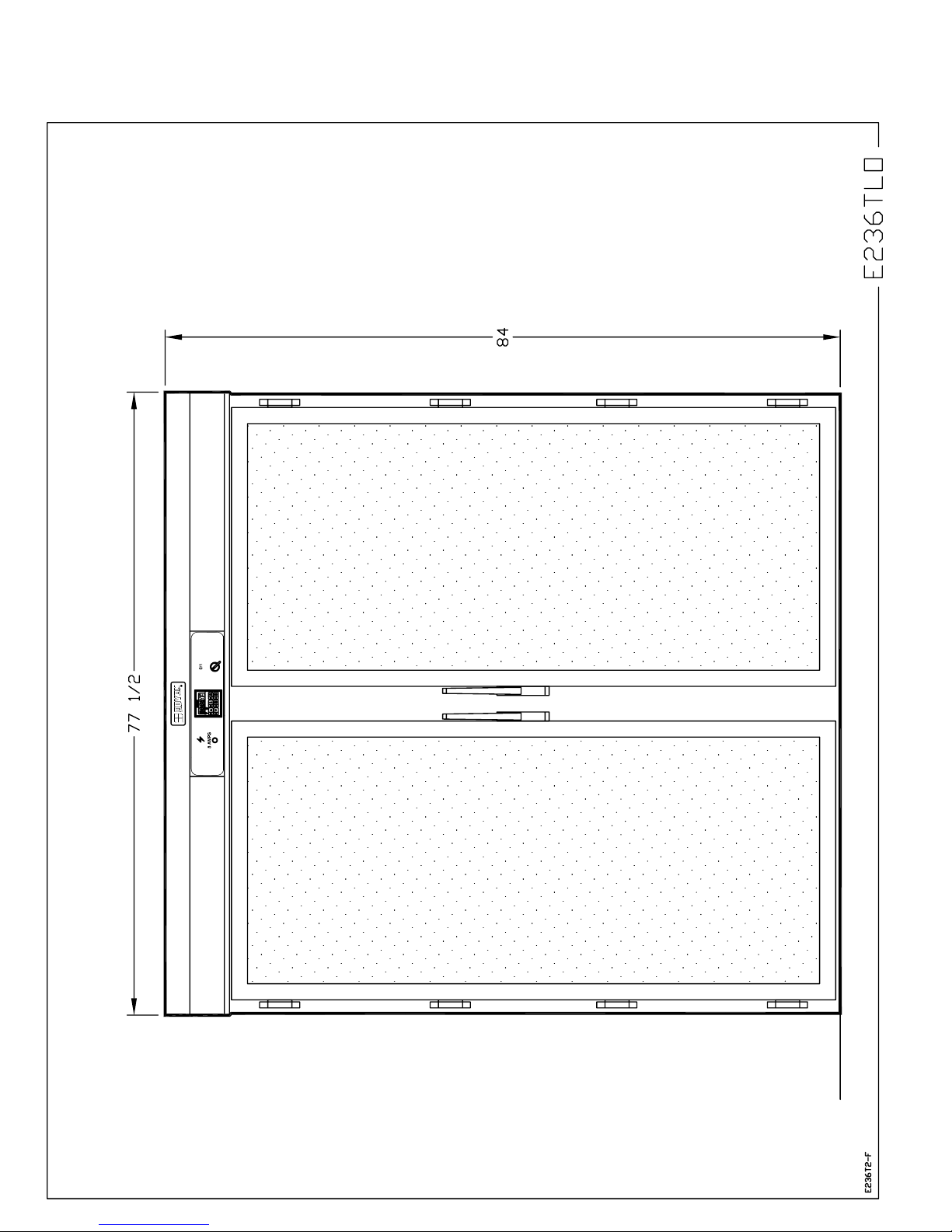
E236 TLO . . . . . . . . . . . . . . . . . . . . . . . . . . . . . . . . . . . . . . . . . . . . . . . . . B3
E336 TLO. . . . . . . . . . . . . . . . . . . . . . . . . . . . . . . . . . . . . . . . . . . . . . . . . . B6
E460 TLO. . . . . . . . . . . . . . . . . . . . . . . . . . . . . . . . . . . . . . . . . . . . . . . . . . B9
SECTION « E » COMPONENT PARTS
Front view component parts for all models . . . . . . . . . . . . . . . . . . . . . . . . E1
DRIP1 TLO . . . . . . . . . . . . . . . . . . . . . . . . . . . . . . . . . . . . . . . . . . . . . . . . E3
E236 TLO. . . . . . . . . . . . . . . . . . . . . . . . . . . . . . . . . . . . . . . . . . . . . . . . . . E5
E336 TLO. . . . . . . . . . . . . . . . . . . . . . . . . . . . . . . . . . . . . . . . . . . . . . . . . . E9
E460 TLO. . . . . . . . . . . . . . . . . . . . . . . . . . . . . . . . . . . . . . . . . . . . . . . . . . E11
Page 2

SECTION « G » ELECTRIC SCHEMATICS
DRIP1 TLO - 120V/208V/1PH & 120V/240V/1PH . . . . . . . . . . . . . . . . G1
DRIP1 TLO - 220V/1PH/50 Hz . . . . . . . . . . . . . . . . . . . . . . . . . . . . . . . . G2
E236 TLO - 120V/208V/1PH & 120V/240V/1PH . . . . . . . . . . . . . . . . . . G3
E236 TLO - 220V/1PH/50HZ . . . . . . . . . . . . . . . . . . . . . . . . . . . . . . . . . . G4
E336 TLO - 120V/208V/1PH & 120V/240V/1PH . . . . . . . . . . . . . . . . . . G5
E336 TLO - 220V/1PH/50HZ . . . . . . . . . . . . . . . . . . . . . . . . . . . . . . . . . . G6
E460 TLO - 120V/208V/1PH & 120V/240V/1PH . . . . . . . . . . . . . . . . . . G7
E460 TLO - 220V/1PH/50HZ . . . . . . . . . . . . . . . . . . . . . . . . . . . . . . . . . . G8
Warranty . . . . . . . . . . . . . . . . . . . . . . . . . . . . . . . . . . . . . . . . . . . . . . . . . . .
FAM-ET-A.DOC REV. 28/11/2005
Page 3

A1
INSTALLATION AND MAINTENANCE MANUAL
The manufacturer suggests to read this manual carefully.
This proofer is manufactured with first quality material by experienced technicians. Proper
installation and maintenance will guarantee a reliable service for years to come.
A nameplate fixed to the front of the proofer specifies the serial number, model number, number of
phase, amperage, voltage and frequency.
Drawings, electrical diagram and replacement part numbers are included in this manual. The
electrical diagram is affixed in the control panel located on the top of the proofer.
ATTENTION
DOYON is not responsible for damages to the property or the equipment caused
by personnel who is not certified by known organizations. The customer is
responsible for finding qualified technicians in electricity and plumbing for the
installation of the oven.
Page 4

A2
C O N S T R U C T I O N
You just bought the most advanced proofer in the world, the "DOYON" technology at its best. This
proofer is manufactured using the highest quality components and material.
The DOYON equipments are designed with parts that are easy to find.
S H I P P I N G
For your safety, this equipment is verified by qualified technicians and carefully crated before
shipment. The freight company assumes full responsibility concerning the delivery in good condition
of the equipment in accepting to transport it.
IMPORTANT
RECEPTION OF THE MERCHANDISE
Take care to verify that the received equipment is not damaged before signing the delivery receipt. If
a damage or a lost part is noticed, write it clearly on the receipt. If it is noticed after carrier left,
contact immediately the freight company in order that they do their inspection.
We do not assume the responsibility for damages or losses that may occur during transportation.
Page 5

A3
W A R N I N G S
FOR YOUR SAFETY
DO NOT STORE OR USE GASOLINE OR OTHER FLAMMABLE VAPORS
AND LIQUIDS IN THE VICINITY OF THIS OR ANY APPLIANCE.
INSTALLATION AND SERVICE
Installation and service must be done by specialized technicians. Contact a certified electrician and
plumber for set up.
The proofer must be connected to the utility and electrically grounded in conformity to the effective
local regulations. If these are not established, the oven must be connected according to the Canadian
Electrical Code (CSA-C22.1-XX) or National Electrical Code (NFPA 70-XX). Refer to last
edition year for XX.
Page 6

A4
DISTANCES TO RESPECT
• Top of the proofer: a clearance of 24 to 36 inches to the ceiling must exist to permit
maintenance.
• Back and sides: 4 inches.
I N S T A L L A T I O N
IN GENERAL
Take off the packaging material with care. Take off all the material used for packing and accessories.
Each unit is set up to be used with the electrical supply specified on the nameplate fixed on the front
of the unit.
1. To the electrician
Electrical supply installation must be in accordance with the electrical rating on the nameplate.
WARNING
The electrician must make sure that the supply cable does not come in contact
with the oven top which becomes hot.
2. To the plumber
This equipment is to be installed to comply with the applicable federal, state, or local plumbing
codes.
Connect the steam system (1/4 NPT) to the water distribution network.
We highly recommend to use a water softener to eliminate minerals in the water. We suggest you to
use CUNO # CFS6135 (Doyon part number PLF240).
WARNING
Do not adjust the needle valves, it has been done at the factory.
Page 7
A5
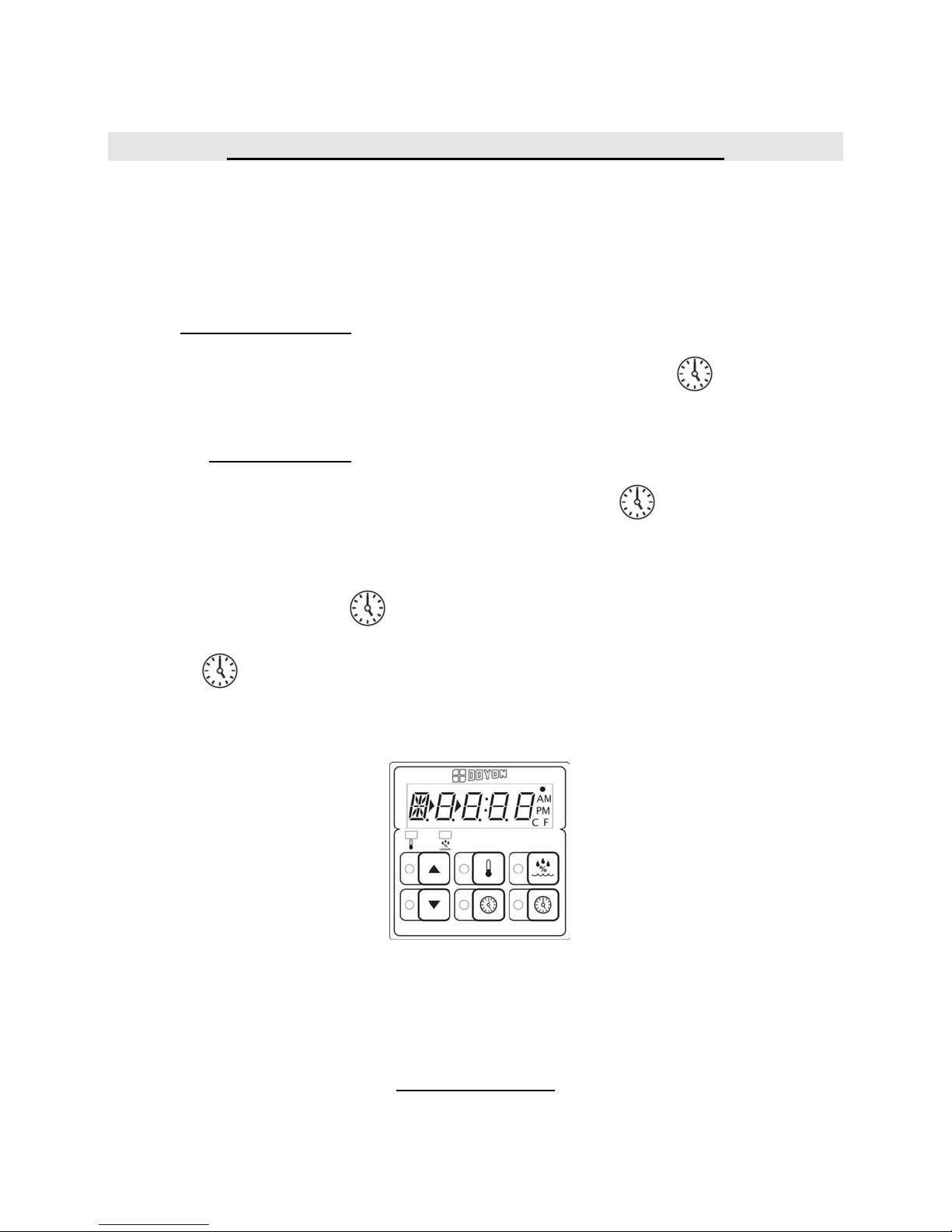
OPERATION OF THE DIGITAL CONTROL
1. Turn the main switch to " 1 ".
2. The light inside the proofer will turn ON and the digital control will indicate a code. Then,
"PREH" will flash.
3. "PREH" will be displayed on the control until it reaches the set temperature.
To check and modify:
Temperature settings : Press and hold down for 2 seconds the temperature key
and adjust with the UP and DOWN arrows. Then, press
temperature key to save data or " red " to exit
without saving.
Humidity settings : Press and hold down for 2 seconds the humidity key and
adjust with the UP and DOWN arrows. Then, press
humidity key to save data or "red " to exit without
saving.
4. When the control reaches the set parameters, "PREH" will disappear and the timer display will
appear.
To start the timer, press " green ", the timer will stop blinking and start countdown.
At the end of the countdown an alarm will go off and " READY " will appear on the display.
Press " red " to stop the alarm.
5. When proofing cycle is completed, turn OFF the switch.
When the proofer is not in operation, open the doors to let out the humidity and prevent
mould.
P.S. The doors should not be opened unnecessarily to conserve the heat and humidity in the
proofer. The water pan under the proofer's doors should be cleaned daily.
When the power comes back, the proofer will start automatically. It is recommended, when a power
failure occurs, to turn off the unit in order to avoid it from starting without supervision.
POWER FAILURE
Page 8

A6
TROUBLESHOOTING
BEFORE CALLING FOR SERVICE,
ANSWERS TO THE MOST FREQUENT QUESTIONS
Always cut off the main power before replacing any parts. Take care of water piping and
electric cable.
Control parts on the front.
Control panel, proofer unit and refrigeration
units.
Questions Solutions
The unit does not turn on when installed.
The blower runs but the unit does not
produce heat.
To remove parts from front panels, you have to
go on the top of the unit.
They are located on the top of the unit.
Check if the light is on.
Check if the proofer’s switch is on.
Check the breaker of the building.
Check the breakers located on the front and in
the electrical control panel on the top of the
unit.
Make sure that the thermostat is adjusted to the
desired temperature (over ambient temperature)
and that the pilot light is lit. Check the breakers
in the electrical control panel.
The blower runs but the unit does not
produce steam.
Check humidity control settings. Verify if the
water valve of the building is open and if water
goes into the proofer’s unit located on the top
of the unit. Check if the water needle valve (of
the unit) is opened between a half to one turn.
Just close it and open it one turn maximum.
Check the breakers in the electrical panel.
Page 9

A7
MAINTENANCE AND CLEANING
Step by step Recommendations
Clean the inside of the unit with water and
soap.
Clean the unit exterior with a stainless steel
polish.
Clean the windows with products like Brasso
or equivalents. They are copper cleaners but
good for this use.
We recommend and sell:
Dirt Buster III : Action foam cleaner
CHEMCO
Part number : NEB201
We recommend and sell:
Stainless steel cleaner
SANY or CURTIS (comestible)
Part number : NES201
We recommend and sell:
Wright's: Cream copper cleaner
J.A. Wright & Co.
Part number : EXC300
Page 10
A8
Page 11

A9
FOR MORE INFORMATION,
PLEASE CONTACT OUR OFFICE:
DOYON EQUIPMENT INC.
1255, rue Principale
Linière, Qc, Canada G0M 1J0
Tel. : 1 (418) 685-3431
Canada : 1 (800) 463-1636
U.S. : 1 (800) 463-4273
FAX : 1 (418) 685-3948
Internet: www.doyon.qc.ca
E-Mail : doyon@doyon.qc.ca
Page 12

SECTION
B
DIMENSIONS
Page 13
B1
Page 14
B2
Page 15
B3
Page 16

B4
Page 17

B5
Page 18

B6
Page 19

B7
Page 20

B8
Page 21

B9
Page 22

B10
Page 23

B11
Page 24

SECTION
E
COMPONENT PARTS
Page 25

E1
Page 26

E2
Item Part Number Description Quantity
1 ELB096 5A BREAKER 1
2 ELT540 ELECTRONIC RELATIVE HUMIDITY CONTROL 1
AND ELT542 DECAL FOR ELT540 1
3 ELI550 MAIN SWITCH (SELECTOR) 1
AND ELI555 CONTACT BLOCK 1NO 1
4 ELF660 VAPOR TYPE FIXTURE 1
5 ELA275 BULB 60W 130V 1
AND ELF650 PLASTIC BULB PROTECTOR 1
6 QUP520 MAGNETIC HANDLE 2
7 P2969E PROOFER DOOR 29 x 69 1/4 2
AND QUE500 DOOR GASKET(19`) 2
8 QUP320 DOOR HINGE 8
Model : E236TLO View : FRONT
Page 27

E3
Page 28

E4
Item Part Number Description Quantity
1 ELM731 MOTOR BLOWER 115 CFM 1
2 ELE168 IMMERSION ELEMENT 240V 3000W 1
OR ELE169 IMMERSION ELEMENT 208V 3000W 1
3 ELE134 COIL ELEMENT 240V 4000W 1
OR ELE133 COIL ELEMENT 208V 4000W 1
4 QUF350 ELECTRIC FLOAT 1
5 ELS880 SOLENOID VALVE 110/120V 50/60Hz 1
6 PLF100 WATER FILTER 1
7 ELV590 NEEDLE VALVE 1
8 ELL050 GROUND LUG 1
9 ELB072 TERMINAL BLOCK 3P 175A 1
10 ELC615 RELAY 10A 2P COIL 110V 1
AND ELC617 BASE 1
11 ELB081 20A DOUBLE BREAKER 1
12 ELB082 30A DOUBLE BREAKER 1
13 ELC908 HEATING CONTACTOR 2
14 ELM735 SOLID STATE TIMER ICM 1
15 ELT720 TRANSFORMER 240/120V 200VA(MODEL 220V ONLY) 1
16 ELC630 CONTROL RELAY 12A COIL 120V 1
AND ELC640 CONTROL RELAY BASE 1
17 ELM736 LOAD FOR TIMER 1
18 ELT541 PROBE FOR ELT540 1
Model : DRIP1TLO View : TOP
Page 29

E5
Page 30

E6
Item Part Number Description Quantity
1 ELM731 MOTOR BLOWER 115 CFM 1
2 ELE168 IMMERSION ELEMENT 240V 3000W 1
OR ELE169 IMMERSION ELEMENT 208V 3000W 1
3 ELE134 COIL ELEMENT 240V 4000W 1
OR ELE133 COIL ELEMENT 208V 4000W 1
4 QUF350 ELECTRIC FLOAT 1
5 ELS880 SOLENOID VALVE 110/120V 50/60Hz 1
6 PLF100 WATER FILTER 1
7 ELV590 NEEDLE VALVE 1
8 ELL050 GROUND LUG 1
9 ELB072 TERMINAL BLOCK 3P 175A 1
10 ELC615 RELAY 10A 2P COIL 110V 1
AND ELC617 BASE 1
11 ELB081 20A DOUBLE BREAKER 1
12 ELB082 30A DOUBLE BREAKER 1
13 ELC908 HEATING CONTACTOR 2
14 ELM735 SOLID STATE TIMER ICM 1
15 ELC630 CONTROL RELAY 12A COIL 120V 1
AND ELC640 CONTROL RELAY BASE 1
16 ELM736 LOAD FOR TIMER 1
17 ELT541 PROBE FOR ELT540 1
Model : E236TLO View:TOP
Page 31

E7
Page 32

E8
Item Part Number Description Quantity
1 ELM731 MOTOR BLOWER 115 CFM 1
2 ELE168 IMMERSION ELEMENT 240V 3000W 1
OR ELE169 IMMERSION ELEMENT 208V 3000W 1
3 ELE134 COIL ELEMENT 240V 4000W 1
OR ELE133 COIL ELEMENT 208V 4000W 1
4 QUF350 ELECTRIC FLOAT 1
5 ELS880 SOLENOID VALVE 110/120V 50/60Hz 1
6 PLF100 WATER FILTER 1
7 ELV590 NEEDLE VALVE 1
8 ELB071 TERMINAL BLOCK 2P 175A 1PHASE 1
9 ELL050 GROUND LUG 1
10 ELT711 TRANSFORMER 120/240 TO 120/240, 350VA 50 Hz 1
11 ELB081 20A DOUBLE BREAKER 1
12 ELB082 30A DOUBLE BREAKER 1
13 ELC908 HEATING CONTACTOR 2
14 ELC615 RELAY 10A 2P COIL 110V 1
AND ELC617 BASE 1
15 ELM735 SOLID STATE TIMER ICM 1
16 ELM736 LOAD FOR TIMER 1
17 ELC630 CONTROL RELAY 12A COIL 120V 1
AND ELC640 CONTROL RELAY BASE 1
18 ELT541 PROBE FOR ELT540 1
Model : E236TLO 220V View:TOP
Page 33

E9
Page 34

E10
Item Part Number Description Quantity
1 ELM731 MOTOR BLOWER 115 CFM 2
2 ELE168 IMMERSION ELEMENT 240V 3000W 2
OR ELE169 IMMERSION ELEMENT 208V 3000W 2
3 ELE134 COIL ELEMENT 240V 4000W 2
OR ELE133 COIL ELEMENT 208V 4000W 2
4 QUF350 ELECTRIC FLOAT 2
5 ELS880 SOLENOID VALVE 110/120V 50/60Hz 2
6 PLF100 WATER FILTER 2
7 ELV590 NEEDLE VALVE 2
8 ELT505 HIGH LIMIT TEMPERATURE 300° 1
9 ELL050 GROUND LUG 1
10 ELB072 TERMINAL BLOCK 3P 175A 1
OR ELB071 TERMINAL BLOCK 2P 175A 1PHASE(MODEL 220V 50 Hz ONLY) 1
11 ELC615 RELAY 10A 2P COIL 110V 2
AND ELC617 BASE 2
12 ELB084 40A DOUBLE BREAKER 1
13 ELC908 HEATING CONTACTOR 3
14 ELB087 50A DOUBLE BREAKER 1
15 ELM735 SOLID STATE TIMER ICM 2
16 ELM736 LOAD FOR TIMER 2
17 ELT720 TRANSFORMER 240/120V 200VA(MODEL 220V 50Hz ONLY) 1
18 ELC630 CONTROL RELAY 12A COIL 120V 2
AND ELC640 CONTROL RELAY BASE 2
19 ELT541 PROBE FOR ELT540 1
Model : E336TLOII View : TOP
Page 35

E11
Page 36

E12
Item Part Number Description Quantity
1 ELM731 MOTOR BLOWER 115 CFM 2
2 ELE168 IMMERSION ELEMENT 240V 3000W 2
OR ELE169 IMMERSION ELEMENT 208V 3000W 2
3 ELT505 HIGH LIMIT TEMPERATURE 300° 1
4 ELE134 COIL ELEMENT 240V 4000W 2
OR ELE133 COIL ELEMENT 208V 4000W 2
5 QUF350 ELECTRIC FLOAT 2
6 ELS880 SOLENOID VALVE 110/120V 50/60Hz 2
7 PLF100 WATER FILTER 2
8 ELV590 NEEDLE VALVE 2
9 ELB072 TERMINAL BLOCK 3P 175A 1
10 ELB084 40A DOUBLE BREAKER 1
11 ELB087 50A DOUBLE BREAKER 1
12 ELL050 GROUND LUG 1
13 ELM735 SOLID STATE TIMER ICM 2
14 ELC908 HEATING CONTACTOR 3
15 ELC615 RELAY 10A 2P COIL 110V 2
AND ELC617 BASE 2
16 ELM736 LOAD FOR TIMER 2
17 ELC630 CONTROL RELAY 12A COIL 120V 2
AND ELC640 CONTROL RELAY BASE 2
18 ELT541 PROBE FOR ELT540 1
Model : E460TLO 60HZ View : TOP
Page 37

E13
Page 38

E14
Item Part Number Description Quantity
1 ELM731 MOTOR BLOWER 115 CFM 2
2 ELE168 IMMERSION ELEMENT 240V 3000W 2
OR ELE169 IMMERSION ELEMENT 208V 3000W 2
3 ELT505 HIGH LIMIT TEMPERATURE 300° 1
4 ELE134 COIL ELEMENT 240V 4000W 2
OR ELE133 COIL ELEMENT 208V 4000W 2
5 QUF350 ELECTRIC FLOAT 2
6 ELS880 SOLENOID VALVE 110/120V 50/60Hz 2
7 PLF100 WATER FILTER 2
8 ELV590 NEEDLE VALVE 2
9 ELC615 RELAY 10A 2P COIL 110V 2
AND ELC617 BASE 2
10 ELB084 40A DOUBLE BREAKER 1
11 ELB087 50A DOUBLE BREAKER 1
12 ELB071 TERMINAL BLOCK 2P 175A 1PHASE 1
13 ELL050 GROUND LUG 1
14 ELM735 SOLID STATE TIMER ICM 2
15 ELM736 LOAD FOR TIMER 2
16 ELC630 CONTROL RELAY 12A COIL 120V 2
AND ELC640 CONTROL RELAY BASE 2
17 ELC908 HEATING CONTACTOR 3
18 ELT728 XFO 120>240V A 120>240V 500 VA 50 HZ 1
19 ELT541 PROBE FOR ELT540 1
Model : E460TL0 50HZ View:TOP
Page 39

SECTION
G
ELECTRIC SCHEMATICS
Page 40

G1
NL1
L2
5 A.
30 A
30 A
ON/OFF
C1
C1
C2
4.0 KW
HEAT
BULB
FAN
LIQUID
LEVEL
5
R1
3
PROOFER
VALVE
AN−2
TIMER
T2
5 SEC.
8
R1
7
AC−IN
BACK VIEW
DC−IN/OUT AC−OUT
SERIAL
LINK
3
1
1234
1234
5768
3
P1
2
7
1
5
AN−1
PROBE
LOAD
20 A
20 A
C2
P1
1 4
8 5
3.0 KW
HUMIDITY
120 / 208 1.0A 33.6A 32.6A
120 / 240 1.0A 30 A 29 A
TOTAL POWER: 7.0 Kw 60 Hz
DRIP1 TLO 1 PHASE 60 Hz
22/08/05 M. FAUCHER 6
NONE
STANDARD
DRIP1T_1
1 / 1
Page 41

G2
1 / 1
T2
TIMER
LEVEL
LIQUID
2
5 SEC.
LOAD
P1
8
5
7
R1
R1
DRIP1T1R
AN−1
5
4
3
21
AC−IN
7
BACK VIEW
PROOFER
3
VALVE
86
4
7
3
AC−OUTDC−IN/OUT
21
5
LINK
SERIAL
PROBE
1
3
1
3
AN−2
DRIP1 TLO 1 PHASE 50 Hz
220 27.3A 27.3A 6 Kw
208 33.6A 33.6A 7.1Kw
22/08/05 M. FAUCHER 7
240 30A 30A 7.1Kw
STANDARD
NONE
TOTAL POWER: 50 Hz
5 A.
250VA
120−240V
120−240V>
ON/OFF
2 A.
X1
H1
FAN
X3
H3
X2
H2
BULB
X4
H4
C2
C1
C1
30 A
HEAT
4.0 KW AT 208V
4.0 KW AT 240V
(3.4 KW AT 220V)
30 A
P1
1 4
C2
20 A
2.5 KW AT 220V
3.0 KW AT 208V
3.0 KW AT 240V
8 5
HUMIDITY
20 A
NL1
Page 42

G3
T2
TIMER
LEVEL
LIQUID
5 SEC.
8
5
R1
R1
2
7
3
LOAD
7
P1
PROOFER
FAN
VALVE
12345
AC−IN
BACK VIEW
1234
DC−IN/OUT AC−OUT
1
7
3
68
5
LINK
SERIAL
1
3
AN−1
PROBE
AN−2
1 / 1
E236TLO
STANDARD
E236TLO 1 PHASE 60 Hz
220 37A 37A 8.0Kw
208 35A 35A 7.2Kw
22/08/05 M. FAUCHER 1
240 31A 31A 7.2Kw
NONE
TOTAL POWER: 60 Hz
5 A.
X1
If 240 V light bulb
If 120 V light bulb
250 VA
240/120 V.
NOTE:
H1
ON/OFF
2 A.
60W
BULB
60W
BULB
120V
240V
X2H2
C2
C1
C1
30 A
HEAT
4.0 KW AT 240V
4.0 KW AT 208V
(4.4 KW AT 220V)
C2
P1
20 A
3.0 KW AT 240V
3.0 KW AT 208V
1 4
8 5
HUMIDITY
(3.4 KW AT 220V)
L2
L1
Page 43

G4
1 / 1
E336T_1
T2
TIMER
LEVEL
LIQUID
5 SEC.
8
5
5 SEC.
R2
R2
5
LOAD
7
2
P2
4
12345
AC−IN
7
BACK VIEW
PROOFER
VALVE
3
P1
4
1
C1
3
12
DC−IN/OUT AC−OUT
13
7
68
5
LINK
SERIAL
31
AN−1
AN−2
PROBE
STANDARD
E336TLOII 1 PHASE 60 HZ
120 / 208 3.5A 70.8 A 67.3 A
VOLTAGE N L1 L2
22/08/05 M. FAUCHER 6
120 / 240 3.5A 61.8 A 58.3 A
NONE
TOTAL POWER: 14.5 Kw 60 Hz
LOAD
2
7
P1
T3
TIMER
LEVEL
LIQUID
8
7
R1
R1
PROOFER
VALVE
3
P2
4
1
C2
T°
FAN
FAN
BULB
ON/OFF
5 A.
L2
L1N
HIGH
LIMIT
300°F
C3
50 A
3 KW
ELEMENT
HUMIDITY
4 KW
HEAT
C3
ELEMENTS
C1
40 A
3 KW
ELEMENT
HUMIDITY
C2
Page 44

T2
TIMER
LEVEL
LIQUID
5 SEC.
8
5
G5
1 / 1
E336T_1R
LOAD
2
7
P1
T3
TIMER
7
R1
LEVEL
PROOFER
VALVE
LIQUID
R1
3
5 SEC.
8
R2
5
LOAD
7
2
P2
4
12345
AC−IN
7
R2
BACK VIEW
PROOFER
VALVE
3
3
12
DC−IN/OUT AC−OUT
13
7
68
5
LINK
SERIAL
31
AN−1
AN−2
PROBE
STANDARD
E336TLOII 1 PHASE 50 HZ
NONE
22/08/05 M. FAUCHER 5
TR1
5 A.
500VA
120−240V>
ON/OFF
120−240V
220 54.6A 54.6 A
VOLTAGE L1 N
P1
4
1
C1
FAN
FAN
X3H3
X1
H1
X2
H2
BULB
H4 X4
T°
HIGH
4
LIMIT
300°F
P2
1
C2
C3
C3
4 KW @ 240
3.4 KW @ 220
HEAT
ELEMENTS
C1
3 KW @ 240
2.5 KW @ 220
HUMIDITY
ELEMENT
C2
3 KW @ 240
2.5 KW @ 220
HUMIDITY
ELEMENT
TOTAL POWER: 12.0 Kw 50 Hz
5 A.
N
L1
50 A
40 A
Page 45

G6
1 / 1
E460T_1
T2
TIMER
LEVEL
LIQUID
2
5 SEC.
8
R1
R1
5
3
LOAD
P1
7
7
PROOFER
VALVE
T3
TIMER
LEVEL
LIQUID
5 SEC.
8
R2
5
LOAD
7
2
P2
4
12345
AC−IN
7
R2
PROOFER
VALVE
3
P1
4
BACK VIEW
1
C1
3
12
DC−IN/OUT AC−OUT
13
7
68
5
LINK
SERIAL
31
AN−1
AN−2
PROBE
STANDARD
E460TLO 1 PHASE 60 HZ
120 / 208 3.5 A 70.8 A 67.3 A
VOLTAGE N L1 L2
22/08/05 M. FAUCHER 6
120 / 240 3.5A 61.8 A 58.3 A
NONE
TOTAL POWER: 14.5 Kw 60 Hz
P2
4
1
C2
T°
HIGH
LIMIT
300°F
FAN
FAN
BULB
ON/OFF
5 A.
L2
L1N
C3
50 A
C3
4 KW
HEAT
ELEMENTS
C1
40 A
3 KW
ELEMENT
HUMIDITY
3 KW
ELEMENT
HUMIDITY
C2
Page 46

G7
1 / 1
E460T_1R
T2
TIMER
LEVEL
LIQUID
5 A.
5 SEC.
8
R1
5
LOAD
2
7
P1
T3
TIMER
7
R1
LEVEL
LIQUID
PROOFER
VALVE
3
5 SEC.
8
5
LOAD
7
2
P2
4
12345
AC−IN
7
R2
BACK VIEW
R2
PROOFER
VALVE
3
3
12
DC−IN/OUT AC−OUT
13
7
68
5
LINK
SERIAL
31
AN−1
AN−2
PROBE
STANDARD
E460TLO 1 PHASE 50 HZ
NONE
22/08/05 M. FAUCHER 5
220 73.5A 73.5 A
FAN
FAN
T°
HIGH
4
4
LIMIT
300°F
VOLTAGE N L1
P1
1
C1
P2
1
C2
C3
TOTAL POWER: 16.2 Kw 50 Hz
X3H3
X2
H2
H4 X4
BULB
TR1
N
L1
500VA
120−240V>
ON/OFF
5 A.
X1
120−240V
H1
50 A
C3
4 KW @ 208 V
4.5 KW @ 220 V
ELEMENTS
HEATING
C1
40 A
3 KW @ 208 V
3.4 KW @ 220 V
HUMIDITY
ELEMENT
C2
3 KW @ 208 V
3.4 KW @ 220 V
HUMIDITY
ELEMENT
Page 47

G8
LIMITED WARRANTY
(Continental United States Of America And
Canada Only)
Doyon Equipment Inc. guarantees to the original purchaser only that
its product are free of defects in material and workmanship, under
normal use.
This warranty does not cover any light bulbs, thermostat calibration or
defects due to or resulting from handling, abuse, misuse, nor shall it
extend to any unit from which the serial number has been removed or
altered, or modifications made by unauthorized service personnel or
damage by flood, fire or other acts of God. Nor will this warranty
apply as regards to the immersion element damaged by hard water.
The extent of the manufacturer’s obligation under this warranty shall
be limited to the replacement or repair of defective parts within the
warranty period. The decision of the acceptance of the warranty will
be made by Doyon Equipment service department, which decision
will be final.
The purchaser is responsible for having the equipment properly
installed, operated under normal conditions with proper supervision
and to perform periodic preventive maintenance.
If any parts are proven defective during the period of one year from
date of purchase, Doyon Equipment Inc. hereby guarantees to replace,
without charge, F.O.B. Linière, Quebec, Canada, such part or parts.
Doyon Equipment Inc will pay the reasonable labor charges in
connection with the replacement parts occurring within one year from
purchase date. Travel over 50 miles, holiday or overtime charges are
not covered. After one year from purchase date, all labor and
transportation charges in connection with replacement parts will be the
purchaser’s responsibility.
Doyon Equipment Inc. does hereby exclude and shall not be liable to
purchaser for any consequential or incidental damages including, but
not limited to, damages to property, damages for loss of use, loss of
time, loss of profits or income, resulting from any breach or warranty.
In no case, shall this warranty apply outside Canada and continental
United States unless the purchaser has a written agreement from
Doyon Equipment Inc.
 Loading...