

Page 1

1
E2330PA
E2330PM/PMC
120 1 Phase 60Hz
IMPORTANT SAFETY INSTRUCTIONS
SAVE THESE INSTRUCTIONS
DANGER
TO REDUCE THE RISK OF FIRE OR ELECTRIC SHOCK,
CAREFULLY FOLLOW THESE INSTRUCTIONS
TABLE OF CONTENTS
DESCRIPTION PAGE
Installation and maintenance manual . . . . . . . . . . . . . . . . . . . . . . . . . . . . . 2
Construction . . . . . . . . . . . . . . . . . . . . . . . . . . . . . . . . . . . . . . . . . . . . . . . . 3
Shipping . . . . . . . . . . . . . . . . . . . . . . . . . . . . . . . . . . . . . . . . . . . . . . . . . . . . 3
Warnings . . . . . . . . . . . . . . . . . . . . . . . . . . . . . . . . . . . . . . . . . . . . . . . . . . . 4
Distances to respect . . . . . . . . . . . . . . . . . . . . . . . . . . . . . . . . . . . . . . . . . . . 5
Installation . . . . . . . . . . . . . . . . . . . . . . . . . . . . . . . . . . . . . . . . . . . . . . . . . . 5
Model option description and front panel symbol signification . . . . . . . . 7
Operation of unit . . . . . . . . . . . . . . . . . . . . . . . . . . . . . . . . . . . . . . . . . . . . . 8
Before calling for service - Answers to most frequent questions . . . . . . . 9
Maintenance and cleaning . . . . . . . . . . . . . . . . . . . . . . . . . . . . . . . . . . . . . . 9
For more information, please call our office: . . . . . . . . . . . . . . . . . . . . . . . 10
Dimensions E2330, PA, PM. . . . . . . . . . . . . . . . . . . . . . . . . . . . . . . . . . . . 12
Dimensions E2330PMC . . . . . . . . . . . . . . . . . . . . . . . . . . . . . . . . . . . . . . 14
Component parts . . . . . . . . . . . . . . . . . . . . . . . . . . . . . . . . . . . . . . . . . . . . . 16
Electric schematic . . . . . . . . . . . . . . . . . . . . . . . . . . . . . . . . . . . . . . . . . . . . 21
Warranty . . . . . . . . . . . . . . . . . . . . . . . . . . . . . . . . . . . . . . . . . . . . . . . . . . . 22
E2330_F.DOC
REV. 2003-09-25
Page 2

2
INSTALLATION AND MAINTENANCE MANUAL
The manufacturer suggests to read this manual carefully.
This proofer is manufactured with first quality material by experienced technicians. Proper
installation and maintenance will guarantee a reliable service for years to come.
A nameplate fixed to the front of the proofer specifies the serial number, model number, number of
phase, amperage, voltage and frequency.
Drawings, electrical diagram, and replacement part numbers are included in this manual. The
electrical diagram is affixed in the control panel located on the top of the proofer.
ATTENTION
DOYON is not responsible for damages to the property or the equipment caused
by personnel who is not certified by known organizations. The customer is
responsible for finding qualified technicians in electricity and plumbing for the
installation of the oven.
Page 3

3
C O N S T R U C T I O N
You just bought the most advanced proofer in the world, the "DOYON" technology at its best. This
proofer is manufactured using the highest quality components and material.
The DOYON equipments are designed with parts that are easy to find.
S H I P P I N G
For your safety, this equipment is verified by qualified technicians and carefully crated before
shipment. The freight company assumes full responsibility concerning the delivery in good condition
of the equipment in accepting to transport it.
IMPORTANT
RECEPTION OF THE MERCHANDISE
Take care to verify that the received equipment is not damaged before signing the delivery receipt. If
a damage or a lost part is noticed, write it clearly on the receipt. If it is noticed after carrier left,
contact immediately the freight company in order that they do their inspection.
We do not assume the responsibility for damages or losses that may occur during transportation.
Page 4

4
W A R N I N G S
FOR YOUR SAFETY
DO NOT STORE OR USE GASOLINE OR OTHER FLAMMABLE VAPORS
AND LIQUIDS IN THE VICINITY OF THIS OR ANY APPLIANCE
IMPORTANT
INSTALLATION AND SERVICE
Installation and service must be done by specialized technicians. Contact a certified electrician and
plumber for set up.
The proofer must be connected to the utility and electrically grounded in conformity to the effective
local regulations. If these are not established, the oven must be connected according to the Canadian
Electrical Code (CSA-C22.1- XX) or National Electrical Code (NFPA 70-XX). Refer to last
edition year for XX.
Page 5

5
DISTANCES TO RESPECT
• Top of the proofer: a clearance of 24 to 36 inches to the ceiling must exist to permit
maintenance.
• Back and sides: 1 inches.
I N S T A L L A T I O N
IN GENERAL
Take off the packaging material with care. Take off all the material used for packing and
accessories..
Each unit is set up to be used with the electrical supply specified on the name plate fixed on the front
of the unit.
1. To the electrician.
Electrical supply installation must be in accordance with the electrical rating on the nameplate.
2. To the plumber.
Connect the steam system (1/4 pipe) to the water distribution network.
Warning
Do not adjust the needle valves it has been done at the factory.
3. To the plumber
This equipment is to be installed to comply with the applicable federal, state or local plumbing codes.
Connect the steam system (1/4 NPT) to the cold water distribution network. We highly
recommend a water softener to eliminate minerals in the water. We suggest to use CUNO #
CFS6135 (Doyon part number PLF240).
Page 6
6
MODELS OPTION DESCRIPTION
E 2330PA Proofer only - 50°F TO 110°F Automatic water entry 1/4" pipe
120 / 1 / 60 – 1500 WATTS 12.5 AMPS
E 2330PM/PMC Proofer only -50°F TO 110°F Manualy fill
120 / 1 / 60 – 1500 WATTS 12.5 AMPS
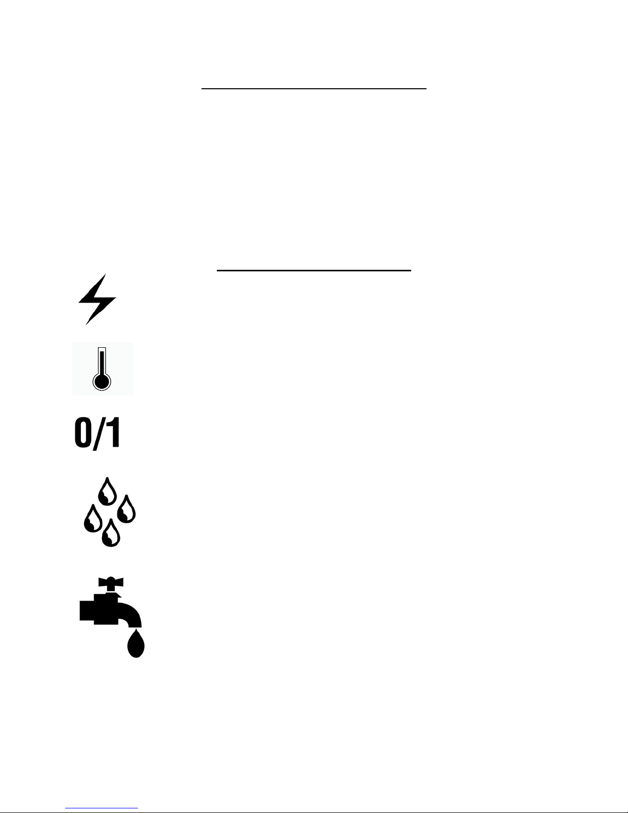
front panel symbol signification
breaker
temperature control
main power switch
humidity control
fill water pan
Page 7

7
O P E R A T I O N
IMPORTANT
FOR THE MANUAL FILL WATER PAN OPTION USE DISTILLATE WATER ONLY.
1. Switch "ON".
2. Set the thermostat control at 100-105o F.
3. Set the humidity control at 5.
If there is too much fog and water drips from the glass doors, adjust humidity control to a lower
number.
4. When the temperature is stabilized, put the products in the proofer
(Leave them inside until they are ready to bake.)
5. When proofing cycle is completed, turn the switch "OFF".
6 If you have the optional manual water fill when the water tank pilot light on front panel stay on
the water tank is empty. Fill the water tank with distillate water.
When the proofer is not in operation, open the doors to let out the humidity and then prevent
mold .
P.S. The doors should not be opened unnecessarily to conserve the heat and humidity in the
proofer.
Every day cleaning of the water pan under the proofer's doors should be exercised.
POWER FAILURE
When the power comes back, the proofer will start automatically. Then it is recommended to turn off
the unit to avoid it starting without supervision.
Page 8

8
Before calling for service
answers to MOST frequent questions
Always cut off the main power before replacing any parts. Take care of water piping and
electric cable.
Control parts on the front:
Control panel, proofer unit.
Questions Solutions
The unit does not turn on when installed.
The blower runs but the unit does not
produce heat.
The blower runs but the unit does not
produce steam.
The water pan red light stay on
To remove parts from front panels, you have to
go on the top of the unit.
They are located on the top.
Check if the light is on.
Check if the proofer switch is on.
Check the breaker of the building.
Check the breaker on the front panel and the
fuses in the electrical control panel.
Make sure that the thermostat is adjusted to the
desired temperature (over ambiant temperature)
and the pilot light will go on.
Make sure that the humidity control is set at
about 5.
Check if the water valve of the building is open
and if water goes into the proofer unit located
on the top of the unit.
Check the water needle valve on top of the
proofer is open two turn. Just close it and open
it two-turn maximum (for manual water fill
open the needle valve completely).
Check the main breaker.
No more water in the optional manual fill water
tank. Fill the water tank whit distillate water
Check and clean the screen filter located on top
of the unit between the tank and electric valve
Check the float switch contact
Page 9

9
UNIT maintenance and cleaning
Step by step Recommendations
Clean the inside of the unit with water and
soap
Clean the unit exterior with a stainless steel
polish.
Clean the water system on the top of the
unit.
We recommend and sell:
Blast : Concentrated for industrial use
KEM Mfg Canada
Part number : NEB201
Warning: Never use cleaners such as EasyOff or equivalents in the oven.
We recommend and sell:
Stapol: Stainless steel polish
KEM Mfg Canada
Part number : NES201
Twice a year clean the water pan and the
immersion element, the water tank if is manual
fill unit and the screen filter.(SEE NEXT
PAGE)
Is very important to use distillate water whit the
manual water fill option and a high quality
water filter on automatic water inlet system to
prevent water line obstruction and scale
problem in the water thank.
Page 10

10
For more information, please contact our office :
DOYON EQUIPMENT INC.
1255, rue Principale
Linière, Qc, Canada G0M 1J0
Tel. : 1 (418) 685-3431
Canada : 1 (800) 463-1636
U.S. : 1 (800) 463-4273
FAX : 1 (418) 685-3948
Internet: www.doyon.qc.ca
E-Mail : doyon@doyon.qc.ca
Page 11

11
E2330PA/PM
DIMENSIONS
Page 12

12
Page 13

13
E2330PMC
DIMENSIONS
Page 14

14
Page 15

15
E2330
COMPONENT PARTS
Page 16

16
Page 17

17
Item Part Number Description Quantity
1 ELT627 THERMOSTAT 110F 1
AND ELT628 THERMOSTAT KNOB 110F 1
AND ELT620 THERMOSTAT BEZEL 1
2 ELL650 PILOT LIGHT 3
3 ELI220 INFINITY SWITCH 120V (HUMIDITY CONT.) 1
AND ELI240 INFINITY SWITCH KNOB 1
4 ELI550 MAIN SWITCH (SELECTOR) 1
AND ELI555 CONTACT BLOCK 1NO 1
AND ELI556 ON - OFF PLATE 1
5 ELB096 5A BREAKER 1
6 P2031E DOOR 31 3/8 x 20 1/2 FOR E2330 2
7 QUP500 LATCH 2
8 QUP320 DOOR HINGE 4
9 PAR800 SWIVEL CASTER 2
AND PAR850 SWIVEL CASTER WITH BRAKE 2
OR PAR400 WHEEL 2 1/2 INCH(FOR PMC MODEL ONLY) 2
AND PAR450 WHEEL 2 1/2 INCH WITH LOCK(FOR PMC MODEL ONLY) 2
Model : E2330 View : FRONT
Page 18

18
Page 19

19
Item Part Number Description Quantity
1 ELC615 RELAY 10A 2P COIL 110V 1
OR ELC617 BASE 1
2 ELC860 CONTACTOR 2P 30A 110V 1
3 ELF130 FEMALE PLUG 8 PIN 1
4 ELF120 MALE PLUG 8 PIN 1
5 ELS950 BUZZER 120V 1
6 ELM735 SOLID STATE TIMER ICM FOR CH460,JAOP3-G, FC2-G AND E233 2
7 ELM734 MOTOR BLOWER 80 DFM 1
8 ELE126 FORMED ELEMENT 120V 1000W 1
9 ELE164 IMMERSION ELEMENT 120V 500W 1
10 QUF350 ELECTRIC FLOAT 1
11 ELF030 PLUG, 2 POLES 3 WIRES 125V 15A 1
12 ELS880 SOLENOID VALVE 110/120V 50/60Hz 1
13 ELV590 NEEDLE VALVE 1
14 PLF100 WATER FILTER 1
15 ELT504 THERMODISK 145°F (OPTIONEL) 1
Model : E2330 View : TOP
Page 20

20
E2330
ELECTRIC SCHEMATIC
120 VOLTS
Page 21

NL1
21
ON/OFF
C1
LIQUID
LEVEL
5
R1
3
PROOFER
VALVE
R1
TIMER
T2
8
7
TIMER
T1
1 MIN.
110°F AT 12.5A
175°F AT 17A
5 SEC.
WATER
PAN
LIGHT
FILL WATER PAN
OR CHECK WATER LINE INLET
WHEN THE PILOT LIGHT IS ON
L
1KW AT 12.5A
1.5KW AT 17A
HIGH
LIMIT
150°F
HEAT
EACH
LOAD
2
P1
7
PILOT
LIGHT
C1
120 12.5A 12.5A 1.5KW
120 17A 17A 2KW
TOTAL POWER: 60HZ
INFINIT
SWITCH
P
L1
L2
P1
1 4
H1
H2
8 5
E2330 120 VOLTS 1PH 60HZ
23/08/05 M. FAUCHER 2
NONE
STANDARD
500 W
HUMIDITY
PILOT
LIGHT
1 / 1
E2230
Page 22

22
LIMITED WARRANTY
(Continental United States Of America And Canada Only)
Doyon Equipment Inc. guarantees to the original purchaser only that its product are free of defects in
material and workmanship, under normal use.
This warranty does not cover any light bulbs, thermostat calibration or defects due to or resulting
from handling, abuse, misuse, nor shall it extend to any unit from which the serial number has been
removed or altered, or modifications made by unauthorized service personnel or damage by flood,
fire or other acts of God. Nor will this warranty apply as regards to the immersion element damaged
by hard water.
The extent of the manufacturer’s obligation under this warranty shall be limited to the replacement or
repair of defective parts within the warranty period. The decision of the acceptance of the warranty
will be made by Doyon Equipment service department, which decision will be final.
The purchaser is responsible for having the equipment properly installed, operated under normal
conditions with proper supervision and to perform periodic preventive maintenance.
If any parts are proven defective during the period of one year from date of purchase, Doyon
Equipment Inc. hereby guarantees to replace, without charge, F.O.B. Linière, Quebec, Canada, such
part or parts.
Doyon Equipment Inc will pay the reasonable labor charges in connection with the replacement
parts occurring within one year from purchase date. Travel over 50 miles, holiday or overtime
charges are not covered. After one year from purchase date, all labor and transportation charges in
connection with replacement parts will be the purchaser’s responsibility.
Doyon Equipment Inc. does hereby exclude and shall not be liable to purchaser for any consequential
or incidental damages including, but not limited to, damages to property, damages for loss of use,
loss of time, loss of profits or income, resulting from any breach or warranty.
In no case, shall this warranty apply outside Canada and continental United States unless the
purchaser has a written agreement from Doyon Equipment Inc.
 Loading...