

Page 1

ShowVault
Digital Cinema Server
Field Installer Manual
Version 1.5
The English version of this document is the only legally binding
version. Translated versions are not legally binding and are for
convenience only.
____________________________________________________________________________________
SHV.OM.001293.DRM Page 1 of 146 Version 1.5
Doremi Labs
Page 2

Table of Contents
1 Introduction ......................................................................................................................11
1.1 Purpose........................................................................................................................11
1.2 Software Version ..........................................................................................................11
1.3 Contact ........................................................................................................................11
1.4 Drives Insertion ............................................................................................................12
1.4.1 General Rules ........................................................................................................12
1.4.2 HDDs Shipment .....................................................................................................12
1.5 Proper Power Off .........................................................................................................14
2 ShowVault Presentation ...................................................................................................16
2.1 ShowVault Front Panel .................................................................................................16
2.2 ShowVault Rear Panel .................................................................................................18
3 Rear Panel Connectors ....................................................................................................21
3.1 VGA Cable Connection for Server LCD Screen Usage ................................................21
3.2 PCI Express Card On Rear Panel ................................................................................21
3.2.1 PCI Express Card Overview ..................................................................................21
3.3 ShowVault Motherboard Connections ..........................................................................23
3.3.1 Motherboard Connectors .......................................................................................23
3.3.2 Keyboard and Mouse PS-2 Connectors ................................................................ .23
3.3.3 Serial Port ..............................................................................................................23
3.3.4 VGA .......................................................................................................................23
3.3.5 USB Ports ..............................................................................................................23
3.3.6 Ethernet .................................................................................................................23
4 ShowVault IP Address ......................................................................................................25
5 Device Manager ................................................................................................................28
5.1 Projector Management .................................................................................................28
5.1.1 Adding a Projector .................................................................................................28
5.1.2 Removing a Projector ............................................................................................30
5.2 Automation Libraries Management ...............................................................................30
5.2.1 eCNA Device .........................................................................................................30
5.2.2 JNior Device ..........................................................................................................31
5.3 Raw Device ..................................................................................................................32
5.3.1 Raw Device Addition ..............................................................................................32
5.3.2 Raw Device Removal.............................................................................................33
5.4 Serial Device ................................................................................................................33
5.4.1 Adding a Serial Device ...........................................................................................33
5.5 ISE1 Device .................................................................................................................37
5.6 CSS Device ..................................................................................................................37
5.7 3D Configuration ..........................................................................................................37
5.7.1 Projector Configuration for 3D or 48fps ..................................................................37
5.7.2 Dolby 3D Support ..................................................................................................37
5.7.3 RealD 3D Support ..................................................................................................37
5.7.4 Sensio 3D Support .................................................................................................39
5.8 Closed Caption Support ...............................................................................................39
5.9 Subtitle Engine Configuration .......................................................................................39
5.9.1 Process Closed Caption Data as Subtitles .............................................................41
____________________________________________________________________________________
SHV.OM.001293.DRM Page 2 of 146 Version 1.5
Doremi Labs
Page 3

6 Automation Set Up: Macro Editor Usage ........................................................................43
6.1 Macro Editor Interface Overview ..................................................................................43
6.2 Automation Cue Tab ....................................................................................................44
6.2.1 Macro Creation ......................................................................................................44
6.2.2 Action Insertion ......................................................................................................45
6.2.3 Add Delay to the Macro Automation Cue ...............................................................46
6.2.4 Add a GPO Action to the Macro Automation Cue ...................................................47
6.2.5 IMB Input Macro Creation ......................................................................................47
6.2.6 Playback Action Insertion .......................................................................................54
6.2.7 Automation Library Usage .....................................................................................54
6.2.8 Resulting Macro Setting ......................................................................................... 55
6.2.9 Action List Management ........................................................................................56
6.2.10 Macro Saving .....................................................................................................56
6.3 Trigger Cue Tab ...........................................................................................................57
6.3.1 Trigger Cue Tab Overview .....................................................................................57
6.3.2 Trigger Cue Creation .............................................................................................57
6.3.3 Connection to an Event ..........................................................................................58
6.3.1 Connection to a Signal Event .................................................................................59
6.3.2 Trigger Cue Saving ................................................................................................61
6.4 Pre-defined Macro Usage ............................................................................................61
6.5 Default Cues ................................................................................................................61
6.6 Startup Scripts..............................................................................................................61
7 Time/Date Set Up ..............................................................................................................63
7.1 Checking the Time/Date ...............................................................................................63
7.2 Changing the Time Zone ..............................................................................................64
8 Control Panel ....................................................................................................................67
8.1 Account Manager GUI ..................................................................................................68
8.2 Language Setup ................................ ................................................................ ...........72
8.3 License Manager ..........................................................................................................74
8.4 Live Manager ...............................................................................................................77
9 ShowVault Software and Firmware USB Upgrade Instructions ....................................82
9.1 Displaying the Software and Firmware Versions ..........................................................82
9.2 Updating the Software and Firmware via USB .............................................................82
10 ShowVault Linux Terminal Commands ........................................................................85
10.1 Linux Login and Terminal Window (Local Connection) ..............................................85
10.2 Linux Login and Terminal Window (Remote Connection) ..........................................85
10.2.1 Remote Login from a Linux Computer ................................................................85
10.2.2 Remote Login from a Windows PC .....................................................................86
10.3 Generating Status Reports ........................................................................................86
10.4 Software and Firmware Upgrade ..............................................................................87
10.4.1 Sending the Software File to the ShowVault .......................................................87
10.4.2 Performing the Software Upgrade ......................................................................87
10.4.3 Sending the Firmware File to the ShowVault ......................................................87
10.5 Network Restarting ...................................................................................................88
10.6 RAID (Partitions) ................................................................ .......................................88
10.6.1 RAID Failure Identification ..................................................................................88
____________________________________________________________________________________
SHV.OM.001293.DRM Page 3 of 146 Version 1.5
Doremi Labs
Page 4

10.6.2 RAID Reinitialization ...........................................................................................88
10.7 Ingest From Ethernet (FTP Server) ...........................................................................89
10.7.1 Uploading Files to a Remote ShowVault via FTP ................................................89
10.8 Changing the Linux Login Password .........................................................................90
10.9 Changing the Linux Display Resolution .....................................................................90
10.9.1 External VGA ......................................................................................................90
10.9.2 ShowVault Front Panel LCD Screen ...................................................................91
11 Troubleshooting ................................ ................................................................ ............93
11.1 ShowVault BIOS Settings .........................................................................................93
11.1.1 BIOS Setting for SuperMicro X7SBE Motherboard .............................................93
11.2 Server LCD Screen Maintenance (3RU only) ............................................................94
11.2.1 Server LCD Screen Calibration ...........................................................................94
12 XML Structure Used by Macro Editor ..........................................................................96
12.1 AutomationCueMacroList Sample .............................................................................96
12.2 AutomationCueMacroList Structure...........................................................................97
12.2.1 IssueDate Node ................................................................................................ ..98
12.2.2 Issuer Node ........................................................................................................98
12.2.3 Creator Node ......................................................................................................98
12.2.4 AnnotationText Node ..........................................................................................98
12.2.5 AutomationCueMacro Nodes ..............................................................................99
12.2.6 Command Node (optional) ................................................................................ 100
12.2.7 TriggerCue Node (optional) .............................................................................. 103
12.3 Schema .................................................................................................................. 105
12.4 XML Diagram Legend ............................................................................................. 107
12.4.1 Element Symbols .............................................................................................. 107
12.4.2 Model Symbols (compositors) ........................................................................... 108
12.5 Types ...................................................................................................................... 108
12.6 Model Groups and References ............................................................................... 109
13 Netmap Configuration File .......................................................................................... 111
13.1 Overview ................................................................................................................. 111
13.2 Netmap File Structure ............................................................................................. 111
13.3 Sample Netmap File ............................................................................................... 113
13.4 Known Issues ......................................................................................................... 113
14 IMB Presentation ......................................................................................................... 115
14.1 Revision E ............................................................................................................... 115
15 Projector Setups .......................................................................................................... 117
15.1 IMB and Barco Series 2 Projector Set Up ............................................................... 117
15.2 IMB and NEC Series 2 Projector Set Up ................................................................. 117
15.3 IMB and Christie Series 2 Projector Set Up ............................................................. 117
16 GPIO and Audio Pin-Out Schema ............................................................................... 119
16.1 GPIO Pin-Out .......................................................................................................... 119
16.1.1 GPI Pin-Out Information ................................................................................... 119
16.1.2 GPO Pin-Out Information .................................................................................. 119
16.2 Audio AES Pin-Out Information ............................................................................... 120
____________________________________________________________________________________
SHV.OM.001293.DRM Page 4 of 146 Version 1.5
Doremi Labs
Page 5

17 HD-SDI Input ................................................................................................................ 122
18 Dolby Atmos ................................................................................................................ 124
18.1 Dolby CP850 (Audio Processor) Software Version .................................................. 124
18.2 Required Items ....................................................................................................... 124
18.3 ShowVault Server Configuration ............................................................................. 124
18.3.1 ShowVault Cable Configuration ........................................................................ 124
18.3.2 Dolby CP850 (Audio Processor) Cable Configuration ....................................... 127
18.4 Doremi IMB Cable Configuration ............................................................................. 128
18.5 Request DLM (Doremi License Manager) ............................................................... 128
18.6 Adding the Audio Processor .................................................................................... 128
18.7 Playing Dolby Atmos Content .................................................................................. 133
18.8 Verifying Atmos Content ......................................................................................... 134
18.9 Dolby CP850 Web GUI ........................................................................................... 136
18.9.1 Accessing the Dolby CP850 Web GUI .............................................................. 136
18.10 Troubleshooting Tips .............................................................................................. 139
18.10.1 Channels Not Recognized ................................................................................ 139
18.10.2 Dolby Atmos Content Not Recognized .............................................................. 141
18.10.3 KDMs for Dolby Atmos Content (CPL) .............................................................. 141
18.10.4 Dolby Atmos Channel Drop Out ........................................................................ 142
19 Acronyms ..................................................................................................................... 144
20 Document Revision History ........................................................................................ 146
____________________________________________________________________________________
SHV.OM.001293.DRM Page 5 of 146 Version 1.5
Doremi Labs
Page 6
Software License Agreement
The software license agreement can be found at the following location:
http://www.doremicinema.com/warranties.html
Hardware Warranty
The hardware warranty can be found at the following location:
http://www.doremicinema.com/warranties.html
HDMI
The terms HDMI and HDMI High-Definition Multimedia Interface, and the HDMI Logo are
trademarks or registered trademarks of HDMI Licensing LLC in the United States and other
countries.
China Compulsory Certification (CCC)
该产品仅适用于海拔2000米以下地区
该产品仅适用于非热带地区
声 明
此为A级产品,在生活环境中,该产品可能会造成无线电干扰。在这种情况下,可能需要用户对其
干扰采取切实可行的措施。
____________________________________________________________________________________
SHV.OM.001293.DRM Page 6 of 146 Version 1.5
Doremi Labs
Page 7

WARNING
THIS DEVICE MUST BE GROUNDED.
IMPORTANT
Power requirements for electrical equipment vary from area to area. Please ensure that the
ShowVault meets the power requirements in the surrounding area. If in doubt, consult a
qualified electrician or a Doremi Labs dealer.
AVIS
Le voltage peut différer d’un pays a l’autre. Il faut que le ShowVault soit ajusté au voltage du
pays.
LA SOURCE DE PUISSANCE DOIT AVOIR UN CONDUCTEUR CONNECTE A LA TERRE.
Toutes réparations doivent être effectuées par une personne qualifiée. AFIN D’EVITER UN
CHOC ELECTRIQUE, VEUILLEZ NE PAS ENLEVER LE CAPOT.
ShowVault Power Ratings
AC Input: 100-240V~, 6-3A, 60-50Hz
Maximum Power Consumption: 300W
WARNING: MULTIPLE SOURCES OF SUPPLY; DISCONNECT ALL SOURCES BEFORE
SERVICING.
ShowVault Rack Mount and Thermal Information
Maximum operating ambient temperature is 35°C.
Never restrict the air flow through the devices’ fan or vents.
When installing equipment into a rack, distribute the units evenly. Otherwise hazardous
conditions may be created by an uneven weight distribution.
Connect the unit only to a properly rated supply circuit. Reliable earthing (grounding) of
rack-mounted equipment should be maintained.
Protecting Yourself and the ShowVault
Never touch the AC plug with wet hands. Always disconnect the ShowVault from the power
supply by pulling on the plug not the cord. Allow only a Doremi Labs, Inc. dealer or qualified
professional engineer to repair or reassemble the ShowVault. Apart from voiding the warranty,
unauthorized engineers might touch live internal parts and receive a serious electric shock. Do
not put, or allow anyone to put any object, especially metal objects, into the ShowVault. Use
only an AC power supply. Never use a DC power supply.
____________________________________________________________________________________
SHV.OM.001293.DRM Page 7 of 146 Version 1.5
Doremi Labs
Page 8

If water or any other liquid is spilled into or onto the ShowVault, disconnect the power and call a
Doremi dealer. The unit must be well ventilated and away from direct sunlight. To avoid damage
to internal circuitry, as well as the external finish, keep the ShowVault away from direct sources
of heat (heater vents, stoves, radiators). Avoid using flammable aerosols near the ShowVault.
They can damage the surface area and may ignite. Do not use denatured alcohol, paint thinner,
or similar chemicals to clean the ShowVault. This can damage the unit.
Modification of this equipment is dangerous and can result in the functions of the ShowVault
being impaired. Never attempt to modify the equipment in any way. In order to ensure optimum
performance of the ShowVault, select the setup location carefully and make sure the equipment
is used properly. Avoid setting up the ShowVault in the following locations:
In a humid or dusty environment.
In a room with poor ventilation.
On a surface which is not level.
Inside a moving vehicle where it will be subject to vibration.
In an extremely hot or cold environment.
Removable Drives Warning
Removal of the hot swappable hard drives allows access to pins and traces supplying power to
the hard drive backplane. This is considered an energy hazard. Removal of the hard drives
must be performed by a trained service specialist or by trained personnel. The equipment may
only be used in a restricted access area which is not accessible to the general public.
Caution
Battery is located on the motherboard.
Danger of explosion if battery is incorrectly replaced.
Replace only with the same or equivalent type recommended by the manufacturer.
Dispose of used batteries according to the manufacturer’s instructions.
____________________________________________________________________________________
SHV.OM.001293.DRM Page 8 of 146 Version 1.5
Doremi Labs
Page 9
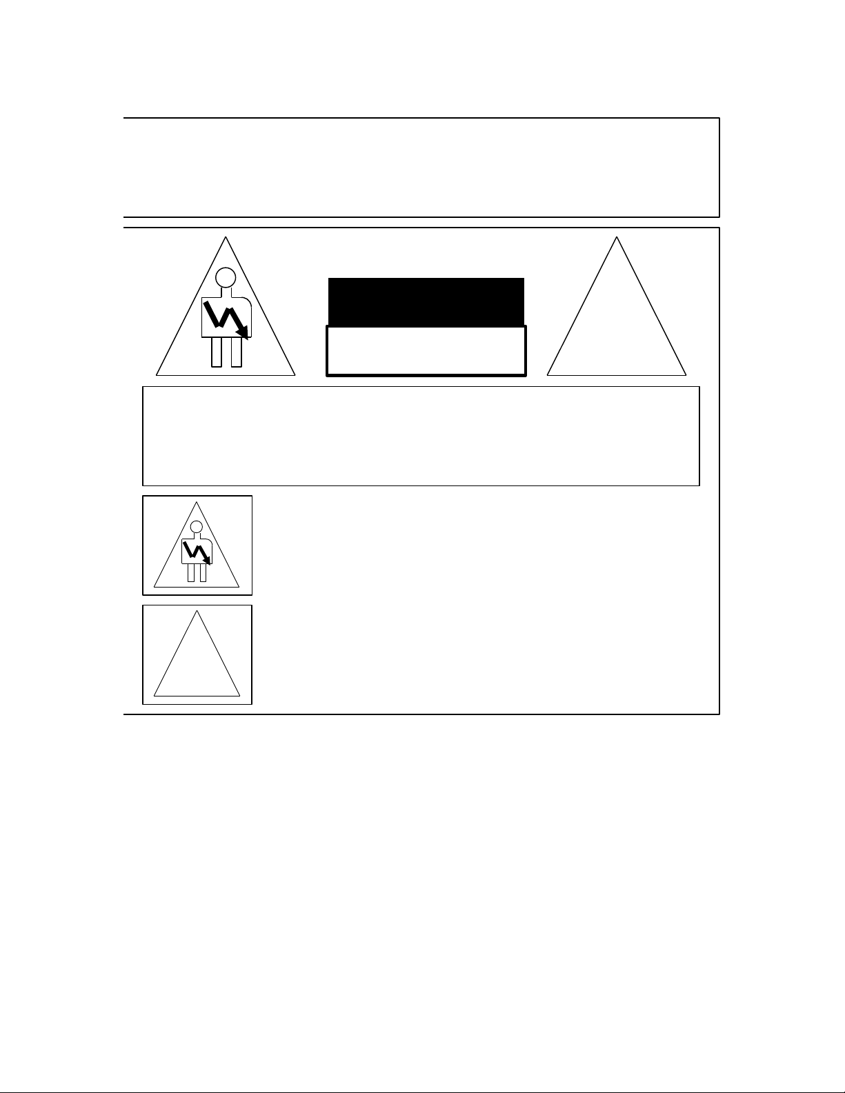
CAUTION
RISK OF ELECTRIC SHOCK
DO NOT OPEN
!
CAUTION: TO REDUCE THE RISK OF ELECTRIC SHOCK,
DO NOT REMOVE COVER (OR BACK).
NO USER-SERVICEABLE PARTS INSIDE.
REFER SERVICING TO QUALIFIED SERVICE PERSONNEL.
The lightning flash with the arrowhead symbol superimposed
across a graphical representation of a person, within an equilateral
triangle, is intended to alert the user to the presence of uninsulated
“dangerous voltage” within the product’s enclosure; that may be
of sufficient magnitude to constitute a risk of electric shock.
!
The exclamation point within an equilateral triangle is intended to
alert the user to the presence of important operating and
maintenance (servicing) instructions in the literature
accompanying the appliance.
WARNING!!
To prevent fire or shock hazard, do not expose this appliance to rain or moisture
____________________________________________________________________________________
SHV.OM.001293.DRM Page 9 of 146 Version 1.5
Doremi Labs
Page 10

CE NOTICE
Marking by the symbol indicates compliance of the device to the EMC (Electromagnetic
Compatibility) directive and to the Low Voltage directive of the European Community. The
marking is indicative that the device meets or exceeds the following technical standards:
EN 55022 "Limits and Methods of Measurement of Radio Interface Characteristics of
Information Technology Equipment".
A "Declaration of Conformity" in accordance with the above standard has been made
and is on file at Doremi.
____________________________________________________________________________________
SHV.OM.001293.DRM Page 10 of 146 Version 1.5
Doremi Labs
Page 11

1 Introduction
1.1 Purpose
This manual is designed to guide the user through the set up and installation of the ShowVault.
1.2 Software Version
This manual is intended for use with software version 2.6.3 and higher.
The IMB SM Versions are:
o 5.1.4 and higher for Barco Series-2, Christie Series-2, and NEC Series-2
Projectors
For previous versions of the software and earlier IMB Revisions, see previous versions
of this document.
1.3 Contact
If in need of help or assistance, please contact Doremi Labs Technical Services:
USA
24/7 Technical Services line: + 1-866-484-4004
Technical Services Email: cinemasupport@doremilabs.com
Europe
24/7 Technical Services line: + 33 (0) 492-952-847
Technical Services Link: http://support.doremitechno.org/ticketing
Japan
Technical Services line: + 044-966-4855
Technical Services Email: support@doremilabs.co.jp
Australia ~ China ~ India ~ Indonesia ~ Korea ~ Malaysia ~ New Zealand ~ Philippines ~
Singapore ~ Taiwan ~ Thailand
Technical Services Email: supportasia@doremilabs.com
____________________________________________________________________________________
SHV.OM.001293.DRM Page 11 of 146 Version 1.5
Doremi Labs
Page 12
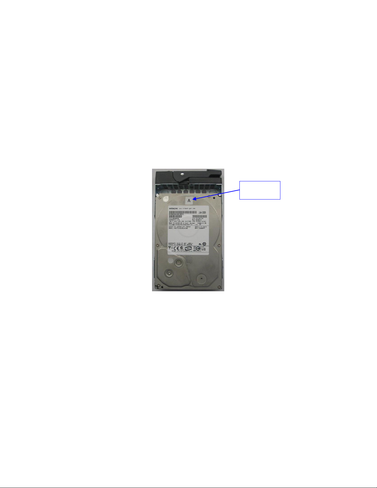
1.4 Drives Insertion
HDD Label
Location
1.4.1 General Rules
In all cases, do not insert or remove drives if the unit is powered on.
Drives are to be of the same make and model, and have the same capacity.
Doremi prohibits mixing SATA I drives with SATA II drives within the same RAID.
1.4.2 HDDs Shipment
Hard disk drives (HDDs) are shipped out of the chassis. In this case, insert them in to the server
before plugging in the power cables according to the procedure presented below:
Identify the label written on each HDD.
There will be one HDD with "A", one HDD with "B", and one HDD with "C" written on
them (Figure 1).
Figure 1: HDD Label Location With “A” Label
For each HDD press on the blue button located on its front side in order to release the
gray handle.
Open the gray handle all the way until it clicks (Figure 2).
____________________________________________________________________________________
SHV.OM.001293.DRM Page 12 of 146 Version 1.5
Doremi Labs
Page 13
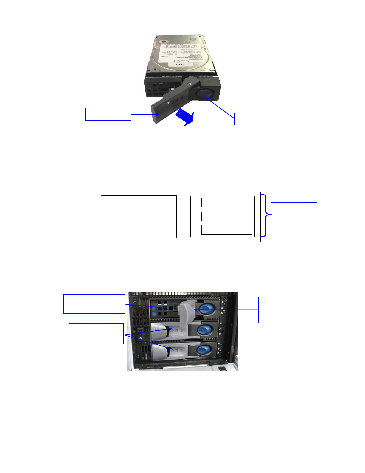
A B C
LCD monitor
Blue button
Gray handle
"B" and "C" HDDs
already installed
"A" HDD inserted into
the HDD cage
Gray handle opened to
insert the HDD
properly
HDD Location
Figure 2: HDD Gray Handle Opening
Open the door covering the HDD case which is located on the right side of the front
panel.
Insert each drive all the way – one by one – into the chassis HDD cage according to the
A-B-C location defined in the schema below (Figure 3).
The gray handle must remain open all the way.
Figure 3: 3RU ShowVault Front View Schema – HDD
The drive must be inserted all the way inside the HDD cage before trying to close the
gray handle (Figure 4).
Close the gray handle by pushing it toward the HDD until it clicks.
____________________________________________________________________________________
SHV.OM.001293.DRM Page 13 of 146 Version 1.5
Figure 4: ShowVault HDD Insertion
Doremi Labs
Page 14

The HDD properly installed will look like the "A", "B", and "C" HDDs presented in Figure
4 above.
Power cables can now be plugged safely into the ShowVault.
1.5 Proper Power Off
Follow the instruction below to power off the ShowVault safely. Any other method might damage
the RAID and result in RAID failure.
Select Shut Down from the Logout menu: Menu → Logout → Shutdown.
Another method to power off the unit is to press and release the power button.
To turn the unit back on simply press and release the power switch.
Note: Do not press and hold the power off button for more than a second. See Section 2.1 for
power switch location.
____________________________________________________________________________________
SHV.OM.001293.DRM Page 14 of 146 Version 1.5
Doremi Labs
Page 15

This page was left blank intentionally.
____________________________________________________________________________________
SHV.OM.001293.DRM Page 15 of 146 Version 1.5
Doremi Labs
Page 16
2 ShowVault Presentation
Thank you for choosing the Doremi ShowVault. The ShowVault is a high quality DCI JPEG2000 server capable of playing movie or trailer packages in MXF format at up to 250Mbits/sec.
The unit features a PCI-Express cable to interface with the IMB unit installed in the projector.
This interface is used to transfer digital cinema files to the IMB which is capable of 12-bit 4:4:4
2048x1080p24 or 10-bit 4:2:2 for 48fps and 3D applications. Data storage is done on an internal
RAID5 disk array.
The ShowVault/IMB also supports MPEG2 Interop movies, pre-show, and alternative content
playback.
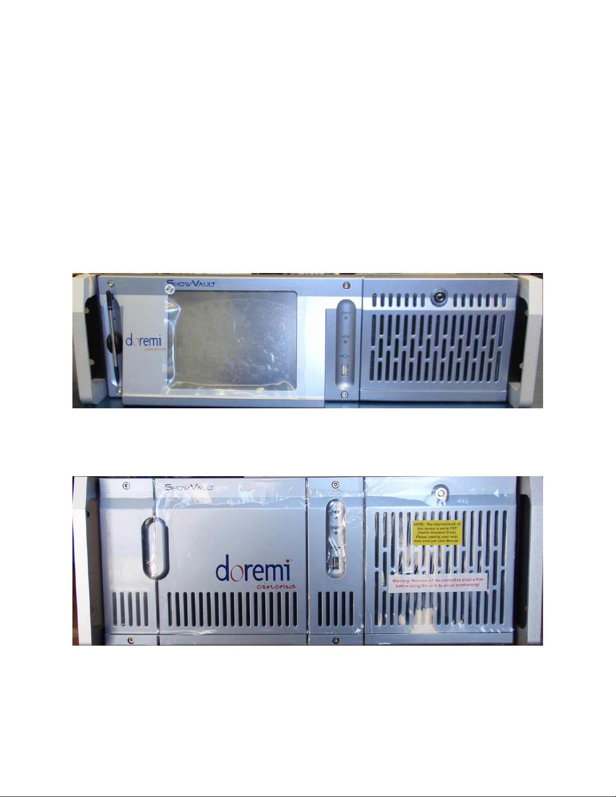
2.1 ShowVault Front Panel
A silver front panel with a LCD screen is shown below (Figure 5):
Figure 5: ShowVault (3RU) with Silver Front Panel
A blue front panel without LCD screen is shown below (Figure 6):
Figure 6: ShowVault (4RU) with Blue Front Panel
POWER (PWR): The LED lights turn green when the unit is powered on.
____________________________________________________________________________________
SHV.OM.001293.DRM Page 16 of 146 Version 1.5
Doremi Labs
Page 17
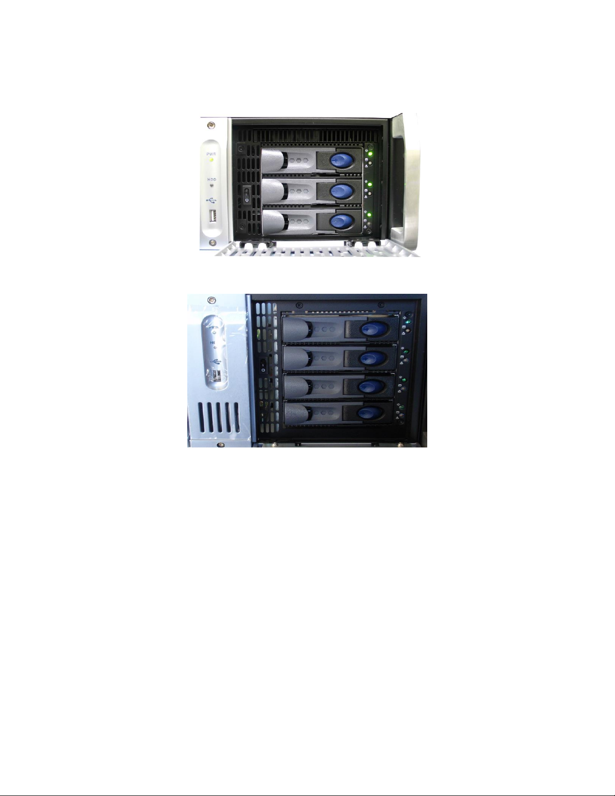
HDD: Red LED light indicates access to the Hard Disk Drives.
The door on the right on both types of units (3RU and 4RU) covers the "POWER" switch
and the three hard disks that make up the RAID5 storage (Figure 7 and Figure 8).
Figure 7: ShowVault (3RU) Silver Front Panel Right Door Opened
Figure 8: ShowVault (4RU) Blue Front Panel Right Door Opened
Each hard disk drive has a blue button that allows removal of the drive from the chassis.
Be careful not to remove the hard disk drive when the ShowVault is running.
There is one USB 2.0 connector on the center of the front panel that can accommodate
an external hard drive as well as a mouse or keyboard.
The left side of the front panel contains an LCD screen (3RU only).
____________________________________________________________________________________
SHV.OM.001293.DRM Page 17 of 146 Version 1.5
Doremi Labs
Page 18
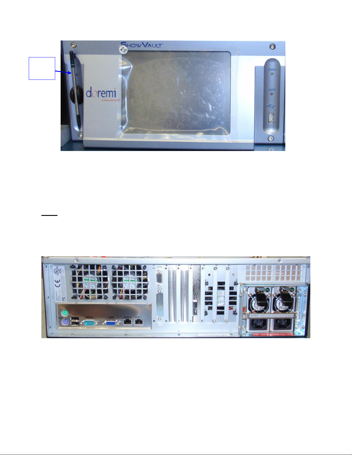
LCD
Power
Button
Figure 9: ShowVault (3RU) Silver Front Panel LCD Screen
On the silver front panel the LCD can be turned on or off by pressing on the LCD power
button using the stylus attached to the front panel. This button is located behind the
stylus (Figure 9).
Note: The use of the LCD screen requires that the two rear panel VGA connectors are linked
using the VGA cable provided with the ShowVault. See section 3.1 for details about the VGA
cable connections.
2.2 ShowVault Rear Panel
Figure 10: ShowVault (3RU) Rear Panel
____________________________________________________________________________________
SHV.OM.001293.DRM Page 18 of 146 Version 1.5
Doremi Labs
Page 19
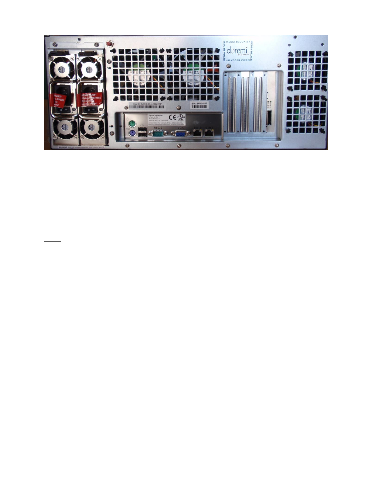
Figure 11: ShowVault (4RU) Rear Panel
On the left side on the rear panel is the dual-redundant power supply
Make sure that two AC power cables are used or the unit will sound an audible alarm
until both power cables are connected
To temporarily disable the audible alarm press the red button next to the AC power
connectors
Note: Insert drives before connecting power cables. Powering the ShowVault with only one AC
cable is not recommended.
On the left side on the rear panel are the motherboard connections. The motherboard
connections are for the keyboard, mouse, VGA, 9-pin serial, Ethernet and USB 2.0
connections (Section 3.3).
____________________________________________________________________________________
SHV.OM.001293.DRM Page 19 of 146 Version 1.5
Doremi Labs
Page 20

This page was left blank intentionally.
____________________________________________________________________________________
SHV.OM.001293.DRM Page 20 of 146 Version 1.5
Doremi Labs
Page 21
3 Rear Panel Connectors
VGA
Connect
VGA
Connect
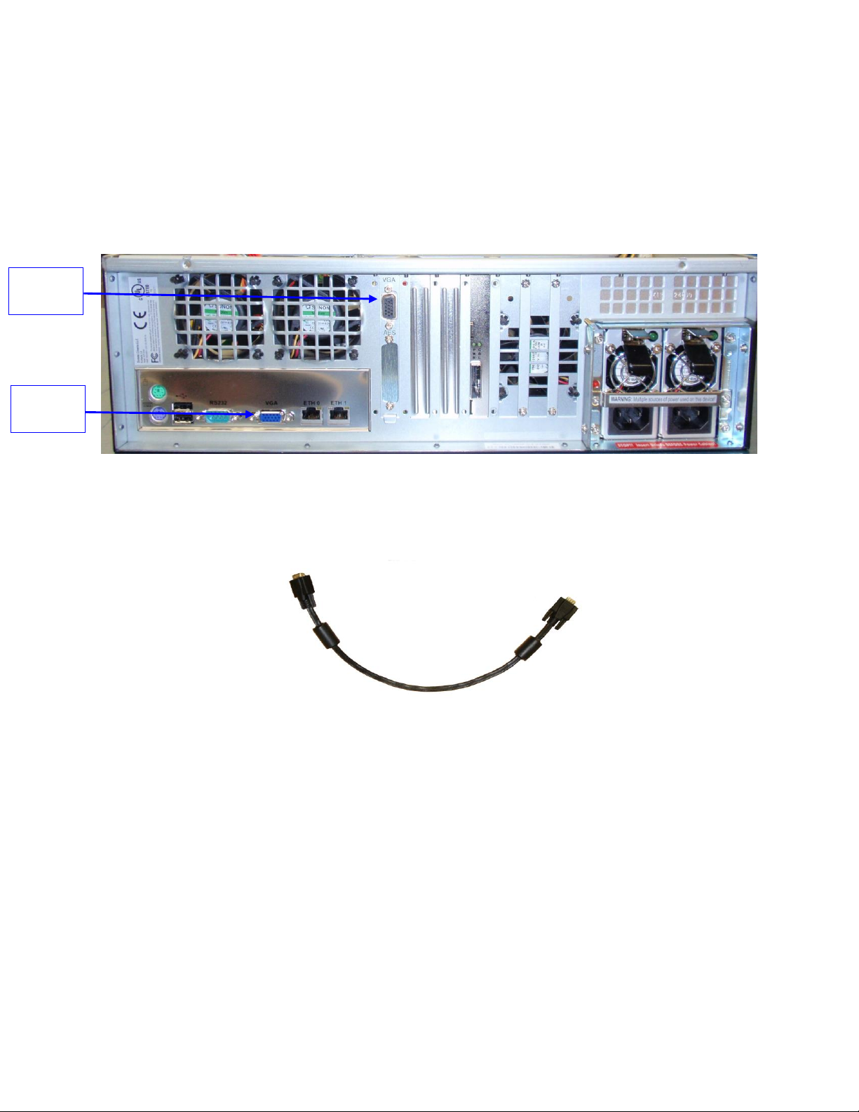
3.1 VGA Cable Connection for Server LCD Screen Usage
If the front panel LCD screen needs to be used (3RU only), the server LCD screen VGA
connector has to be linked to the motherboard VGA connector using the VGA cable (Figure 12).
It is provided with the ShowVault (Figure 13). The VGA cable has to be secured to the
ShowVault VGA connectors using the integrated screws.
Figure 12: ShowVault (3RU) Rear Panel With SuperMicro Motherboard VGA Connector
Figure 13: VGA Cable
3.2 PCI Express Card On Rear Panel
3.2.1 PCI Express Card Overview
On the center of the rear panel are the various card slot connectors. The PCI Express card is
used to connect the ShowVault to the IMB in the projector (Figure 14 and Figure 15).
____________________________________________________________________________________
SHV.OM.001293.DRM Page 21 of 146 Version 1.5
Doremi Labs
Page 22
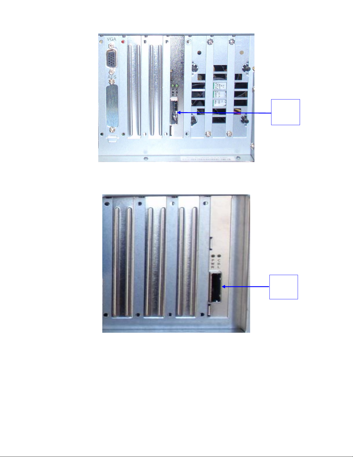
PCI
Express
Card
PCI
Express
Card
Figure 14: ShowVault (3RU) Rear Panel PCI Express Card Slot Connector
Figure 15: ShowVault (4RU) Rear Panel PCI Express Card Slot Connector
____________________________________________________________________________________
SHV.OM.001293.DRM Page 22 of 146 Version 1.5
Doremi Labs
Page 23

3.3 ShowVault Motherboard Connections
Mouse
Keyboar
USB
Ports
Serial
Port
VGA
Port
Ethernet
1
Ethernet 0
3.3.1 Motherboard Connectors
On the rear panel of both the 3RU and 4RU units are the connections to the motherboard. The
motherboard used on the ShowVault is the SuperMicro. The SuperMicro Motherboard
connector is presented in Figure 16. The associated connectors are labeled and described in
the paragraphs 3.3.2 to 3.3.6.
3.3.1.1 SuperMicro Motherboard Connectors
Figure 16: ShowVault (3RU) Rear Panel SuperMicro Motherboard Connectors
3.3.2 Keyboard and Mouse PS-2 Connectors
On the left side of the connector panel are the PS-2 connectors for the PC keyboard and
mouse. These jacks can be used interchangeably, but traditionally the purple jack is for a PC
keyboard and the green jack is for a PS-2 mouse. If the user has a USB keyboard or mouse,
then use the USB ports on the left side of the motherboard connector panel.
3.3.3 Serial Port
This is a standard 9-pin male DB-9 serial COM port on the motherboard.
3.3.4 VGA
Connect a standard VGA monitor to display the ShowVault software user interface.
This connector can also be linked to the center rear panel VGA connector to facilitate use of the
front panel LCD screen. The VGA cable is provided with the ShowVault and is further explained
in section 3.1.
3.3.5 USB Ports
Connect standard USB 2.0 peripherals for a PC USB keyboard, mouse, hard drive, etc.
3.3.6 Ethernet
The Motherboard has two built-in Gigabit Ethernet connectors. The left one is identified as
"Eth0" and the right one is identified as "Eth1".
____________________________________________________________________________________
SHV.OM.001293.DRM Page 23 of 146 Version 1.5
Doremi Labs
Page 24

This page was left blank intentionally.
____________________________________________________________________________________
SHV.OM.001293.DRM Page 24 of 146 Version 1.5
Doremi Labs
Page 25
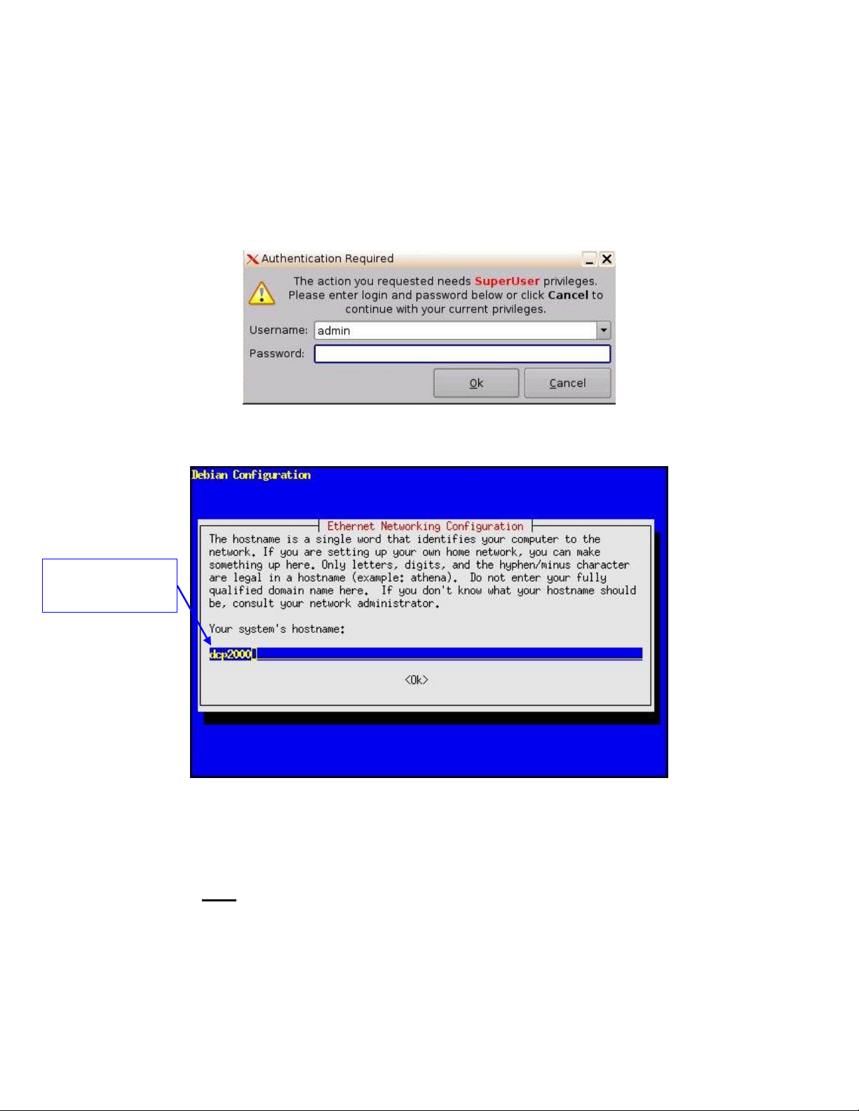
4 ShowVault IP Address
System hostname -
dcp2000 used as an
example
All ShowVault servers are shipped with a default IP address of 192.168.100.50 on the Ethernet
port (Eth1) and a DHCP assigned dynamic IP address on the Ethernet port (Eth0) – see section
3.3 to locate each Ethernet connector.
To change the IP address of the ShowVault server, go to Menu → System → Networking
Configuration and follow the steps below:
A window will appear asking for a password as illustrated below (Figure 17):
Figure 17: Authentication Windows
Follow the steps according to the Ethernet Networking Configuration Wizard (Figure 18):
____________________________________________________________________________________
SHV.OM.001293.DRM Page 25 of 146 Version 1.5
Figure 18: ShowVault Network Configuration
Press Enter to confirm the configuration of each page of the Ethernet Networking
Configuration Wizard. Press Tab to select an option.
Enter the desired system’s hostname and then press Enter.
o Note: It is a good idea to put the circuit location/screen number in here. For
example, “AMC_bir_scr1,” as it will be easier to identify when connecting via
VNC and in the logs.
Enter the desired system domain name and then press Enter.
Doremi Labs
Page 26

Select Yes to set eth0 and then press Enter.
Select No for Removable Device and then press Enter.
Select No for Automatically Configure Device with DHCP and then press Enter.
Enter the desired IP address for eth0 and then press Enter.
Enter the desired default gateway or leave empty and then press Enter.
Enter the desired subnet mask and then press Enter.
Select Yes to configure eth1 and then press Enter.
Select No for Removable Device and then press Enter.
Select No for Automatically Configure Device with DHCP and then press Enter.
Enter the IP address of eth1 and select OK – in the example, enter 192.168.100.50 and
then press Enter.
o Note: Do not put leading zeroes (0) in front of any numbers. For example, do not
input 192.168.100.050.
Enter the desired default gateway or leave empty and then press Enter.
Enter the desired subnet mask and select OK – in our example, enter the same subnet
mask as the projector: 255.255.255.0 and then press Enter.
Enter the IP Address of the System's Domain Name Server (or leave empty) and then
press Enter to exit the wizard.
To verify the setup, go to Menu → Doremi Apps. → Diagnostic Tool and verify the IP Address
under the Diagnostic Tool System Tab.
Note: The configuration for Ethernet 2 that might be asked by the Ethernet configuration wizard
is not needed at this point. It is ok to skip this step if asked for the configuration.
____________________________________________________________________________________
SHV.OM.001293.DRM Page 26 of 146 Version 1.5
Doremi Labs
Page 27

This page was left blank intentionally.
____________________________________________________________________________________
SHV.OM.001293.DRM Page 27 of 146 Version 1.5
Doremi Labs
Page 28
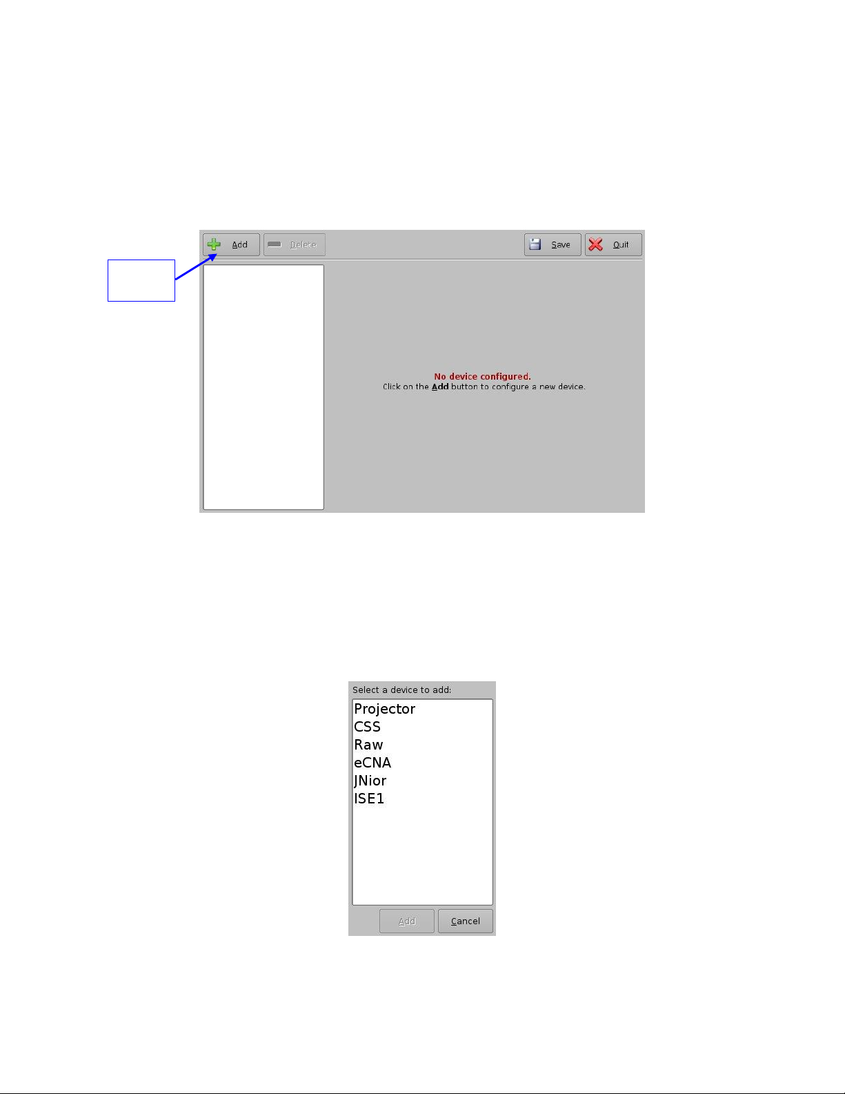
5 Device Manager
Add
button
The Device Manager is a graphical user interface (GUI) used to set up the connection between
a ShowVault and other cinema devices like a cinema projector(s). It also provides for the use of
Ethernet commands for the control of theater automation devices.
To run the Device Manager go to Menu → Doremi Apps. → Device Manager.
The following window will appear on the screen (Figure 19):
Figure 19: Device Manager Graphical User Interface (GUI)
5.1 Projector Management
5.1.1 Adding a Projector
To connect a projector to the ShowVault, click the Add button (Figure 19).
The following window will appear (Figure 20):
Figure 20: Device Manager GUI – Device Selection Window
____________________________________________________________________________________
SHV.OM.001293.DRM Page 28 of 146 Version 1.5
Doremi Labs
Page 29
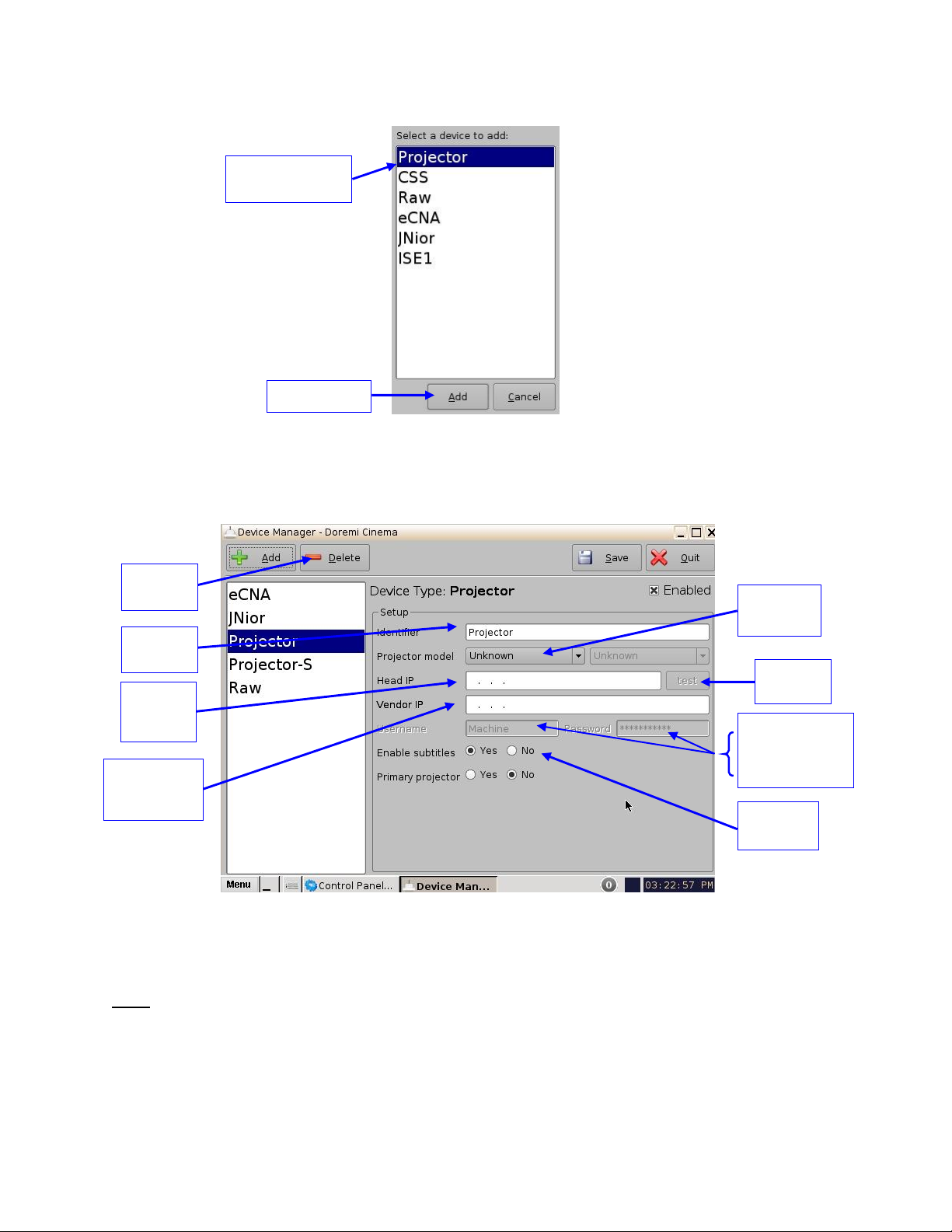
Select Projector and click the Add button (Figure 21):
Add button
Delete
button
Projector item
selected
Projector
Identifier
Projector
model Field
DLP Head
IP Field
Test
Button
DLP Username
and Password
(do not change)
Vendor IP
Field (not
used)
Enable
subtitles
Figure 21: Device Selection Window – Projector Item Selected
The main configuration window will be updated to reflect the addition of the Projector
device. The user will be able to enter the projector parameters as illustrated below
(Figure 22):
Figure 22: Device Manager GUI – Projector Fields Setup
To perform the projector configuration, follow the steps below:
Specify a projector identifier (e.g., projector name, screen #) in the first field.
Note: The selection of primary and secondary projectors only applies to Sony SRX Projectors.
For all other projector types, please select Primary. Also, this could apply if the user were to use
dual projector for 3D (left projector would be Primary and right projector would be Secondary).
____________________________________________________________________________________
SHV.OM.001293.DRM Page 29 of 146 Version 1.5
Doremi Labs
Page 30

Choose the correct projector model to connect to the unit using the Projector model
field(s).
Select the model series for the projector from the drop-down menu on the right. The
projector model series varies for all projector manufacturers.
Enter the Head IP address, and then click the test button.
If the DLP Head Connection Test fails, the IP address is invalid.
Choose to either enable or disable the subtitles.
Note: If the user enables subtitles without the unit being connected to a projector, then the
server will not operate properly.
Check the Enabled check box at the top right corner of the GUI.
Click the Save button to record the settings. A password confirmation page will appear.
Enter the password to save and record the settings.
5.1.2 Removing a Projector
To remove a projector click on its name on the left part of the Device Manager GUI.
Click the Delete button (Figure 22).
5.2 Automation Libraries Management
Support for theater automation control is also provided. The list of currently supported devices is
the following:
eCNA
JNior
A pre-built library of supported automation commands is available for each of these two
devices. These automation commands can then be added to Macro Cues as presented
in Section 6.2.
5.2.1 eCNA Device
5.2.1.1 eCNA Device Addition
To add the eCNA device, click the Add button in the Device Manager window.
The Add Device window will appear. Select eCNA and click the Add button.
The Device Manager GUI will be updated to reflect the addition of the eCNA device.
Input the eCNA Server IP address in the appropriate field (Figure 23):
____________________________________________________________________________________
SHV.OM.001293.DRM Page 30 of 146 Version 1.5
Doremi Labs
Page 31

eCNA IP
address field
Add
button
Enabled
checked
Delete
button
Figure 23: Device Manager GUI – eCNA Device Setup
If not already done, check the Enabled check-box in the top-right corner of the GUI.
Click the Save button to record the settings. A window asking for the password will
appear. Enter the password to save the settings and proceed.
Click Quit when finished with the configuration. If not, continue and add more devices.
5.2.1.2 eCNA Device Removal
To remove the eCNA device, select it in the left pane of the Device Manager and click
the Delete button (Figure 23).
5.2.2 JNior Device
5.2.2.1 JNior Device Addition
To add the JNior device, click the Add button in the Device Manager window.
The Add Device window will appear. Select JNior and click the Add button.
The Device Manager GUI will be updated to reflect the addition of the JNior device
(Figure 24).
Enter the IP address of the JNior device in the Server IP field.
The port number field should already contain the appropriate value (factory default
value).
Note: The JNior device documentation will provide the correct username and password
(factory default values).
____________________________________________________________________________________
SHV.OM.001293.DRM Page 31 of 146 Version 1.5
Doremi Labs
Page 32

JNior IP
address field
Add
button
Delete
button
Figure 24: Device Manager GUI – JNior Device Setup
Click the Save button to record the settings.
A window will appear asking for a password. Enter the password to proceed.
Click Quit when finished with the configuration. If not, continue and add more devices.
5.2.2.2 JNior Device Removal
To remove the JNior device, click on its name on the left part of the Device Manager
GUI.
Click the Delete button (Figure 24).
5.3 Raw Device
5.3.1 Raw Device Addition
A Raw device allows for communication with an external device across an Ethernet connection
using Raw data formatted as text or binary strings.
To add a Raw device, click the Add button.
The Add Device window will appear. Select Raw and click the Add button.
The Device Manager GUI will be updated to reflect the addition of the Raw device
(Figure 25).
Input the name of the Raw device in the Identifier field.
____________________________________________________________________________________
SHV.OM.001293.DRM Page 32 of 146 Version 1.5
Doremi Labs
Page 33

Quit
button
Save
button
Figure 25: Device Manager GUI – Raw Device Set Up
Specify a vendor name in the Vendor field.
Specify a product name in the Product Name field.
Enter the IP address of the Raw device in the Device IP field (Figure 25).
Chose the protocol to be used (TCP or UDP) and the proper Port number.
Click the Save button to record the settings (Figure 25).
A window will appear asking for a password, enter the password to proceed.
If finished with the configuration, click the Quit button.
5.3.2 Raw Device Removal
To remove the Raw device, click on its name on the left part of the Device Manager GUI
and press the Delete button (Figure 25).
5.4 Serial Device
5.4.1 Adding a Serial Device
The Serial device is used to be able to manage incoming and outgoing messages over a
serial port. It is a new feature that allows the user to control or interact with some old
legacy device that usually communicates only through serial cables. Outgoing messages
can be sent to the automation using a simple basic automation cue. Incoming messages
are parsed, and then sent to the playback engine in the form of a signal trigger.
The schema below explains how the daemon is run (Figure 26):
____________________________________________________________________________________
SHV.OM.001293.DRM Page 33 of 146 Version 1.5
Doremi Labs
Page 34

Figure 26: Serial Device Schema
The file device.xml contains all elements to configure properly the serial port and how to
scan incoming messages. This file is conveniently managed by the Device Manager GUI
application. The generic serial device driver can manage different serial ports
simultaneously.
Go to Menu → Doremi Apps. → Device Manager and follow the steps below. The
following window will appear (Figure 27):
Figure 27: Device Manager GUI
Click on the Add button and select Serial from the pop-up list.
____________________________________________________________________________________
SHV.OM.001293.DRM Page 34 of 146 Version 1.5
Doremi Labs
Page 35

Figure 28: Add Device Window
Click the Add button (Figure 28). The following window will appear (Figure 29):
It is necessary to provide some configuration parameters in the window:
◦ Identifier is the friendly name of the new configured device.
◦ Serial Port is the internal device system filename the device driver will communicate
to.
◦ Usual values are: /dev/ttyS0 for embedded serial port on the motherboard and
/dev/ttyUSB0 for any USB-serial converter.
Speed, Data, Stop Bits, Parity and Flow control are usual parameters used to configure
serial communication. Refer to the original automation documentation to find out what
the correct values are. Usual value is 115200 8N1. No flow control.
____________________________________________________________________________________
SHV.OM.001293.DRM Page 35 of 146 Version 1.5
Doremi Labs
Page 36

Figure 29: Device Manager GUI - Serial Device Added
Message type: This parameter indicates how incoming text will be parsed to build
messages. In order to match most existing protocol, two different incoming message
types are handled (Figure 30).
◦ Fixed-length messages: All messages are always expected to be the same length.
The user has to provide the message length parameter.
◦ End of Line Byte message: All messages are expected to have a special "magic"
character to indicate the end of message. This type matches most text-based
protocol with an end of line character (\n) to validate the entry. The user has to
provide the end of message "magic" character. Multiple character sequence is not
supported (e.g., \r\n). Note that the "magic" character will NOT be part of the
message sent to the playback engine.
Save the new configuration by clicking the Save button.
____________________________________________________________________________________
SHV.OM.001293.DRM Page 36 of 146 Version 1.5
Doremi Labs
Page 37

Figure 30: Fixed-length and End of Line Byte Examples
Note: It may take up to 30 seconds before the new configuration is applicable.
After the serial device has been configured, the user can set the trigger from the serial
port or automation actions to serial port.
5.5 ISE1 Device
The ISE1 Device provides for communication with the IMAX Secure Enclosure. If more
information is needed, please contact Doremi Technical Support (Section 1.3).
5.6 CSS Device
The CSS Device provides for communication with the Sony Cavity Security System. If more
information is needed, please contact Doremi Technical Support (Section 1.3).
5.7 3D Configuration
5.7.1 Projector Configuration for 3D or 48fps
When using a ShowVault/IMB configuration for 3D presentation, the projector needs to be set to
the proper color space. Contact the projector vendor to know how to configure the projector
properly.
5.7.2 Dolby 3D Support
To enable the Dolby 3D support, please contact Doremi to purchase the appropriate license.
Refer to the procedure provided in the document, DCP-2000 – Dolby 3D Calibration, or contact
Doremi Technical Support to receive the document.
5.7.3 RealD 3D Support
To enable the RealD 3D support, please contact RealD at cinema-support@reald.com to
receive the appropriate license. Once the license has been received, follow the steps below:
Open the Device Manager GUI by clicking on Menu → Doremi Apps. → Device
Manager.
The following window will appear (Figure 31):
____________________________________________________________________________________
SHV.OM.001293.DRM Page 37 of 146 Version 1.5
Doremi Labs
Page 38

Figure 31: Device Manager GUI
Add
Button
Add
Button
Click the Add button.
The list of available devices will appear (Figure 32):
Figure 32: List of Available Devices
Select the RealD 3D EQ device and click the Add button (Figure 32).
The device will be visible on the main Device Manager GUI (Figure 33):
____________________________________________________________________________________
SHV.OM.001293.DRM Page 38 of 146 Version 1.5
Doremi Labs
Page 39

Figure 33: RealD 3D EQ Device Added
Save
Button
To complete the configuration, click the Save button (Figure 33). Enter the appropriate
password and click Ok.
5.7.4 Sensio 3D Support
To enable the Sensio 3D support, please contact Doremi to get the appropriate license. Then go
to Section 8.3to install the license in the ShowVault and contact Doremi Technical Support
Services to know how to configure a playback using Sensio 3D.
5.8 Closed Caption Support
To enable the Rear Window devices Closed Caption support, install the appropriate license as
explained in Section 8.3. For information about set up, contact Doremi Technical Support.
5.9 Subtitle Engine Configuration
This section provides instructions on how to set up the Device Manager for Subtitle Engine
support. It will allow the user to generate subtitles into the picture before being exported to the
projector. Once the license has been received, follow the steps below:
Open the Device Manager GUI by going to Menu → Doremi Apps. → Device Manager.
The following window will appear (Figure 34):
____________________________________________________________________________________
SHV.OM.001293.DRM Page 39 of 146 Version 1.5
Doremi Labs
Page 40

Add
Button
Figure 34: Device Manager GUI
Click the Add button (Figure 34).
The Add Device window will appear:
Note: In case the user already has a projector configured through Device Manager to display
subtitles, meaning that the Enable subtitle filed was set to Yes, adding the Subtitle Engine
device will cause a warning window to appear asking the user to disable all projector subtitle
display. The Subtitle Engine will generate the subtitle inside the picture before exporting the
resulting pictures to the projector. If the user plans to use the Subtitle Engine, click the Yes
button in the warning window to disable all projector subtitles (Figure 35).
Figure 35: Subtitle Engine Warning Window
Select the Subtitle Engine device and click the Add button.
The device will be visible on the main Device Manager GUI (Figure 36):
____________________________________________________________________________________
SHV.OM.001293.DRM Page 40 of 146 Version 1.5
Doremi Labs
Page 41

Closed
Caption
Data Check
Box
Figure 36: Subtitle Engine Added
To complete the configuration, click the Save button (Figure 36).The user will be asked
for a password. Enter the appropriate password and press Ok.
5.9.1 Process Closed Caption Data as Subtitles
In the event that the DCP being played back does not contain subtitle data but does have
Closed Caption data, you can enable the Doremi server to process the DCPs closed caption
data to generate on screen as a subtitle.
Click the Process Closed Caption Data If No Subtitle Content is Detected check box (Figure 36)
and then click the Save button to retain this setting.
____________________________________________________________________________________
SHV.OM.001293.DRM Page 41 of 146 Version 1.5
Doremi Labs
Page 42

This page was left blank intentionally.
____________________________________________________________________________________
SHV.OM.001293.DRM Page 42 of 146 Version 1.5
Doremi Labs
Page 43

6 Automation Set Up: Macro Editor Usage
Automation Cue tab
Trigger Cue tab
Add
button
Quit
button
Automation events can be created using the Macro Editor for use within the CineLister interface.
The sections below detail how to generate and manage automation events as part of Macro
Automation Cues and/or Trigger Cues.
6.1 Macro Editor Interface Overview
Go to Menu and click on Doremi Apps., then select Macro Editor.
The Macro Editor GUI will appear (Figure 37):
Figure 37: Macro Editor Graphical User Interface (GUI)
The GUI presented above is composed of two different tabs:
◦ Automation Cue tab: used for the creation and editing of Macro Automation Cues.
◦ Trigger Cue tab: used for the creation and editing of Trigger Cues linked to dedicated
Macro events (GPI line #1 ON, execute Macro xxMACRO NAMExx).
The Quit button is used to close the Macro Editor user interface.
____________________________________________________________________________________
SHV.OM.001293.DRM Page 43 of 146 Version 1.5
Doremi Labs
Page 44

6.2 Automation Cue Tab
Insert a New
Action button
Macro Automation
Cue name
Remove
button
Macro Automation
Cue name
displayed
Macro
Window
Settings
button
Use the up and
down arrows to
re-arrange the
order of the
commands
6.2.1 Macro Creation
Click the New Macro button to start the creation of a new Macro Automation Cue (Figure 37).
The following window will be displayed (Figure 38):
Figure 38: Macro Automation Cue Name Assignment
Enter a Macro Automation Cue name in the appropriate field.
This will be the name used by the CineLister application to include the Macro
Automation Cue within a Show Playlist.
Click the Ok button when finished.
The new macro will appear in the Macro Editor Window (Figure 39):
____________________________________________________________________________________
SHV.OM.001293.DRM Page 44 of 146 Version 1.5
Figure 39: Macro Window Updated
To remove a Macro Automation Cue, select it in the Macro window and click the Delete
Macro button (Figure 39).
To edit the name of an existing Macro Automation Cue, click the Settings button or
double-click on the Macro itself (Figure 39).
Use the up and down arrows to re-arrange the Automation Cues.
Click the Save button when finished.
Doremi Labs
Page 45

Selecting the Reset button will close a document without saving the changes. The user
will be prompted to a window asking to save the changes. Use this with caution.
6.2.2 Action Insertion
To insert a new action in a Macro Automation Cue, select its Macro name in the Macro
Window.
Click the Insert a New Action button (Figure 39).
The following window will be displayed (Figure 40).
Figure 40: Add a New Action Window
The Add a New Action window provides a list of available actions, on the left side, to be used
within a Macro Automation Cue. Click on each action, on the left side, to view a list of available
actions. The actions available are the following:
Projector:
◦ Projector Channel Switch: Switch the selected projector channel number.
◦ Projector Dowser: Open or close the selected projector dowser.
◦ Lamp: Power On or off the selected projector lamp.
◦ Macro: Execute the macro defined in the selected projector.
Input / Output:
◦ General Purpose Output: Configure a GPO line.
◦ Send Message: Send a message to the connected device.
Playback:
◦ Audio Volume: Control the audio volume output.
◦ Chase Mode: enables synching of incoming time code
◦ Playback Actions: Change the playback state.
____________________________________________________________________________________
SHV.OM.001293.DRM Page 45 of 146 Version 1.5
Doremi Labs
Page 46

◦ RealD SBS: Enable or disable the RealD SBS output format.
Buttons to increase and
decrease minutes
Buttons to increase and
decrease seconds
◦ Sensio3D: Enable or disable the Sensio3D output format.
◦ Video Output Actions: Change the default video output format.
Macro Control:
◦ Delay: Insert a delay between actions.
◦ Purge Pending Macro: Purge the current macro execution stack.
Library:
◦ Certainty: Controls the Integrated Media Block (IMB) board (on ShowVaults only).
◦ Dolby DFC100: Allows for enabling and disabling the Dolby 3D color wheel.
◦ eCNA: Allows for controlling the external automation box.
◦ JNior Expansion Module: Allows for controlling the external automation box (9-16).
◦ JNior: Allows for controlling the external automation box (1-8).
◦ MasterImage: Controls the MasterImage 3D system
◦ QSC: Controls QSC audio products
System:
◦ System Shutdown: Allows the user to shut down the player.
Click the Cancel button to cancel the action insertion.
To add an action to the Macro Automation Cue, click on its corresponding action button
in the Action window.
6.2.3 Add Delay to the Macro Automation Cue
To add a delay action to the selected Macro Automation Cue, click the Delay button in
the Add a New Action window and define the delay parameter using the following
window (Figure 41):
Figure 41: Delay Setup Window
Click the Ok button when the setting is done.
____________________________________________________________________________________
SHV.OM.001293.DRM Page 46 of 146 Version 1.5
Doremi Labs
Page 47

6.2.4 Add a GPO Action to the Macro Automation Cue
Button used to choose the
GPO line number
Use the minus/plus
buttons to change
the value of the
pulse
To add a GPO action, click the General Purpose Output button, which is located in the
Input/Output section in the Add a New Action window (Figure 40).
The following window will appear (Figure 42)
Figure 42: GPO Set Up Window
Set the line number and value according to the usage and click the Ok button.
6.2.5 IMB Input Macro Creation
This section provides instructions on how to create macros to change video source on the IMB.
First, create a Raw device:
Click on Menu and scroll to Doremi Apps. Then select Device Manager.
The following window will appear (Figure 43):
____________________________________________________________________________________
SHV.OM.001293.DRM Page 47 of 146 Version 1.5
Doremi Labs
Page 48

Figure 43: Device Manager GUI
Click the Add button. The following pop-up window will appear (Figure 44):
Figure 44: Add Device Pop-Up Window
Select Raw and then click the Add button (Figure 45).
____________________________________________________________________________________
SHV.OM.001293.DRM Page 48 of 146 Version 1.5
Doremi Labs
Page 49

Figure 45: Add Device Window
In the Identifier field, change the name from Raw to IMB (Figure 46).
Specify a vendor name in the Vendor field.
Specify a product name in the Product Name field.
In the Device IP field, input the projector's IP address (Figure 46).
The Protocol field should be set to tcp and the Port field should be set to 43751. Click
the Save button when finished entering these values (Figure 46).
A password window will appear asking for the appropriate username and password.
____________________________________________________________________________________
SHV.OM.001293.DRM Page 49 of 146 Version 1.5
Doremi Labs
Page 50

Figure 46: IMB Device Added
o Click the Quit button to exit the Device Manager GUI.
Creating the Macros:
◦ Click on Menu and scroll to Doremi Apps. Then select Macro Editor.
◦ The following window will appear (Figure 47):
____________________________________________________________________________________
SHV.OM.001293.DRM Page 50 of 146 Version 1.5
Doremi Labs
Page 51

Figure 47: Macro Editor GUI
Click the New Macro button (Figure 47). The Macro Settings window will appear (Figure
48):
Figure 48: Macro Settings Window
Name the macro HDMI Input, HDSDI Input, or Internal Input. Click Ok when finished
naming the macro.
◦ Note: The ShowVault incorporates High-Definition Multimedia Interface (HDMI®)
technology.
Click the Insert a New Action button. The following window will appear (Figure 49):
____________________________________________________________________________________
SHV.OM.001293.DRM Page 51 of 146 Version 1.5
Doremi Labs
Page 52

Figure 49: Add a New Action Window
The following window will appear (Figure 50):
A list should appear with many different actions, select "SET_INPUT_HDMI" (or
whichever input is being set up) and click Ok (Figure 50).
◦ Each input should have its own macro created.
Figure 50: Library Window
The following window will appear (Figure 51). Select IMB from the drop-down menu and
click OK.
____________________________________________________________________________________
SHV.OM.001293.DRM Page 52 of 146 Version 1.5
Doremi Labs
Page 53

Figure 51: Send a Message Window
Once all 3 input macros have been created, click on the Save button.
Enter the appropriate username and password.
Click the Quit button when finished to exit the program.
Now each macro can be used to change the video source.
Click on Menu and scroll to Doremi Apps. Then select Macro Execution.
Each macro should be available in the drop-down list. Select the input desired and click
Execute. The following window will appear (Figure 52):
Figure 52: Send a Message Window
A message stating that the macro was created successfully should appear. Click Ok.
____________________________________________________________________________________
SHV.OM.001293.DRM Page 53 of 146 Version 1.5
Doremi Labs
Page 54

6.2.6 Playback Action Insertion
Playback action
selection button
To add a Playback Action, click the Playback Actions button in the Add a New Action
window (Figure 40).
Select Playback and then select Playback Actions.
The following window will appear (Figure 53):
Figure 53: Playback Actions Setup Window
Select the proper playback action between Play, Pause, Toggle Play/Pause, Rewind,
Recue Show, Skip to ShowPlaylist Segment, Skip to Next Clip, and Exit from
Intermission and click the Ok button.
6.2.7 Automation Library Usage
When one of the supported devices (e.g., eCNA and JNior) is added according to Section 5.2,
the Macro Editor will allow the user to use the corresponding commands for each device.
To use a library command, click on Library in the Add a New Action window (Figure 40).
Select one of the available devices in the right part of the window and click the Add
button (Figure 54):
Figure 54: Macro Editor GUI Automation Setup Example
____________________________________________________________________________________
SHV.OM.001293.DRM Page 54 of 146 Version 1.5
Doremi Labs
Page 55

The following pop-up window will appear (Figure 55):
List of actions
inserted into the
Test element
Arrow
buttons
Edit Action
button
Save
button
Remove
button
Selected Macro
automation
Figure 55: Macro Editor GUI – Library Automation Configuration
Select the desired action and click the Ok button, or Cancel to cancel this command.
6.2.8 Resulting Macro Setting
After inserting the three actions “Delay 1 seconds”, “GPO #4 Pulse at 200 ms” and
“Playback: PLAY” in the Macro “Test_Macro” as demonstrated above, the right part of
the Automation Cue tab will display the added actions as presented below (Figure 56):
Figure 56: Example of Macro Actions Window Updated
Click the Save button to save the Test_Macro settings.
Enter the password to save settings and proceed.
____________________________________________________________________________________
SHV.OM.001293.DRM Page 55 of 146 Version 1.5
Doremi Labs
Page 56

6.2.9 Action List Management
6.2.9.1 Action Reordering
The two arrows allow the user to change the order of the actions in the Macro Automation Cue
(Figure 56). Using the arrows, each action can be moved to the top or to the bottom of the
Macro Actions window.
In order to move an action toward the top of the list, select it and click on the arrow
pointing to the top.
If an action needs to be moved toward the bottom of the list, select it and click on the
arrow pointing to the bottom.
Repeat the two steps above until the required actions order is obtained.
6.2.9.2 Action Edition
The user can edit an action of any given Macro Automation Cue by selecting it in the right part
of the interface. The user can also click on the Edit Action button presented in Figure 56. The
user will be able to edit the properties and set the action when added to the Macro Automation
Cue.
6.2.9.3 Action Removal
To remove an action from the list of actions associated to a Macro Automation Cue,
select the action in the Macro Actions window and click the Delete Macro button (Figure
56).
6.2.10 Macro Saving
Repeat the Macro creation operations for all the Macro Automation Cues and click the
Save button.
User will be asked for a password to be able to perform the operation (Figure 57).
Figure 57: Authentication Window
Enter the appropriate password and click the Ok button.
The Macro Automation Cues will be available in CineLister in order to create a Show
Playlist.
Note: The saving operation will not only save the Macro Automation Cues, but also the Trigger
Cues that are created according to the procedure described in Section 6.3.
____________________________________________________________________________________
SHV.OM.001293.DRM Page 56 of 146 Version 1.5
Doremi Labs
Page 57

6.3 Trigger Cue Tab
Add button
Trigger
Window
6.3.1 Trigger Cue Tab Overview
The Trigger Cue Tab is shown below (Figure 58):
Figure 58: Trigger Cue Tab
6.3.2 Trigger Cue Creation
To create a new Trigger Cue, click the Add button.
The same type of window for the Automation Cue tab allowing the user to enter the
Trigger Cue name will appear (Figure 59).
Figure 59: Trigger Cue Setting Window
Enter the appropriate name. It will be the name used by the CineLister application to
insert the Trigger Cue in a Show Playlist.
The newly created Trigger Cue will appear in the Trigger window and it will be ready to
connect to a GPI event (Figure 60).
____________________________________________________________________________________
SHV.OM.001293.DRM Page 57 of 146 Version 1.5
Doremi Labs
Page 58

New Trigger
Cue created
Connect to An
Event button
Edit Trigger
button
Delete
button
General
Purpose Input
Button
Signal Button
Figure 60: Trigger Cue Defined
To edit an existing Trigger Cue, select it in the Trigger window and click on the Edit Trigger
button (Figure 60).
The user will be able to edit the name of the Trigger Cue using the same window as
presented in Figure 59.
To remove a Trigger Cue, select it in the Trigger window and click the Delete button.
6.3.3 Connection to an Event
To connect a Trigger Cue to an event, select it in the Trigger window and click the Connect to
An Event button (Figure 60).
The following window will appear:
Figure 61: Choose the Event to Add Window
To connect the selected Trigger Cue to a GPI event, click the General Purpose Input
button of the Events window (Figure 61).
The following window will appear (Figure 62):
____________________________________________________________________________________
SHV.OM.001293.DRM Page 58 of 146 Version 1.5
Doremi Labs
Page 59

GPI Line
Number Field
Figure 62: Connection to a GPI Event
Define the GPI line number and value to connect to the Trigger Cue and click the Ok
button.
The connected GPI event will then appear in the right part of the GUI.
To connect the selected Trigger Cue to another signal, click the Signal button of the
Events window (Figure 61).
The following window will appear (Figure 63):
Figure 63: Signal Name Window
Click the Ok button when the appropriate signal name is defined.
6.3.1 Connection to a Signal Event
Click the Connect to an Event button from Macro Editor's Trigger Cue tab. The Events
window will appear (Figure 61).
Click the Signal button. The Signal Setup window will appear.
Choose the device from the drop-down menu (Figure 64).
Choose the signal from the drop-down menu (Figure 65).
Click Ok when finished and the connected Signal event will appear in the right part
of the Editor tab.
Note: The “...” button will prompt the Signal Library window to appear (Figure 66). The Signal
Library has a list of additional signals that are not listed in the signal drop-down menu. For
example, the JNior device has a subsidiary device called the JNior Expansion Module.
____________________________________________________________________________________
SHV.OM.001293.DRM Page 59 of 146 Version 1.5
Doremi Labs
Page 60

However, the JNior Expansion Module does not appear in the source device drop-down menu.
Signal
Library
Button
Use the Signal Library button to access all possible signals.
Figure 64: Device Name Window
Figure 65: Signal Setup Window
Figure 66: Signal Library Window
____________________________________________________________________________________
SHV.OM.001293.DRM Page 60 of 146 Version 1.5
Doremi Labs
Page 61

6.3.2 Trigger Cue Saving
Repeat the Trigger Cue creation operations for all the Trigger Cues are created and click
the Save button.
The user will be asked for a password to be able to perform the operation (Figure 67).
Figure 67: Authentication Window
Enter the appropriate password and click the Ok button.
The Trigger Cues will then be available within CineLister in order to be included in a
Show Playlist.
Note: The saving operation will not only save the Trigger Cues, but also the Macro Automation
Cues that were created according to the procedure described in Section 6.2.
6.4 Pre-defined Macro Usage
If the user has a pre-defined macros.xml file containing automation and trigger cue definitions,
then copy it into the /doremi/etc/ folder and the corresponding macros will be visible in the
Macro Editor GUI. The user will then be able to update the cues, if needed, from the Macro
Editor GUI.
6.5 Default Cues
The default_cues.xml file can be used to load an automation and trigger cues playlist prior to
any playback. This is to avoid having to add a Fire Alarm trigger cue to each show. If the user is
provided a default_cues.xml file, copy it into the /doremi/etc/ folder.
6.6 Startup Scripts
Copy the script to be executed automatically at boot in the following folder:
/doremi/etc/rc.d/
____________________________________________________________________________________
SHV.OM.001293.DRM Page 61 of 146 Version 1.5
Doremi Labs
Page 62

This page was left blank intentionally.
____________________________________________________________________________________
SHV.OM.001293.DRM Page 62 of 146 Version 1.5
Doremi Labs
Page 63

7 Time/Date Set Up
Current Date
and Time
Units are by default set to Pacific Time Zone (PST or PDT). This section provides information on
how to check and/or change the time and date.
7.1 Checking the Time/Date
There are two ways to check the current time/date: through the terminal and the GUI.
To confirm, through the GUI, that the time/date of the unit is set correctly, go to Menu → Control
Panel → Time Setting and open the Date/Time tab (Figure 68). Admin privileges are required
to access the application.
Figure 68: Date/Time Tab
To confirm, through the Terminal, that the time/date of the unit is set correctly, open a terminal
window by going to the Menu → System → Terminal menu.
Type: date and then press Enter.
The current date, time, and time zone will be displayed (Figure 69).
Figure 69: Terminal Window with Date Displayed
____________________________________________________________________________________
SHV.OM.001293.DRM Page 63 of 146 Version 1.5
Doremi Labs
Page 64

7.2 Changing the Time Zone
There are two ways to change the current time zone: through the terminal and the GUI.
To change the time zone, through the GUI, go to Menu → Control Panel → Time Setting and
open the Time Zone tab. Using the drop-down menu, select the desired time zone (Figure 70).
Admin privileges are required to access the application.
Figure 70: Time Zone Tab
To change the time zone, through the Terminal, follow the steps below in the terminal window
(Menu → System → Terminal):
Type: su and then press Enter.
Type the root password to log in as root. Consult the system administrator to receive the
root password or Doremi to know the default root password.
Type: rwdo tzconfig and then press Enter.
Type: Yes (to confirm the change).
Select the number of the geographic area for the time change (Figure 71).
____________________________________________________________________________________
SHV.OM.001293.DRM Page 64 of 146 Version 1.5
Doremi Labs
Page 65

Figure 71: Terminal Window with Time Zone Wizard
Once the geographic area number has been selected, press Enter.
Type the name of the city/region of the preferred time zone (e.g., Singapore, Caribbean,
PST, etc.).
Press Enter.
After typing the city/region, the unit will now be set to the desired configuration.
Exit the terminal window.
____________________________________________________________________________________
SHV.OM.001293.DRM Page 65 of 146 Version 1.5
Doremi Labs
Page 66

This page was left blank intentionally.
____________________________________________________________________________________
SHV.OM.001293.DRM Page 66 of 146 Version 1.5
Doremi Labs
Page 67

8 Control Panel
To access the Control Panel window go to Menu → Control Panel.
The following will appear (Figure 72):
Figure 72: Control Panel Window
The Control Panel window provides access to various applications as listed below. See Figure
72 for more information.
Account Manager: Allows the user to add/remove/edit user accounts.
Audio Configuration: Allows the user to route all audio tracks to operator-designated
outputs (only SMPTE content).
Backup Manager: Allows users to backup, delete, and restore files saved on a unit.
Content Feed Manager: Allows the user to add an FTP ingest server.
Content Manager: Allows the user to browse, manage and export all the content
available on the player including: ShowPlaylists, CPLs, KDMs, and Doremi Licenses.
Device Controller: Allows the user to create/edit/register devices in a simplified manner.
Device Manager: Allows the user to add different projectors, close caption devices,
subtitle devices, etc.
Diagnostic Tool: Provides the user with Diagnostic information about the system. See
the document, “Diagnostic Tool User Guide.”
FLMx Manager: Allows the user to manage and export FLMx files.
Language Setup window: Allows the user to change the language used on the unit.
License Manager: Displays and manages software licenses installed on the unit.
____________________________________________________________________________________
SHV.OM.001293.DRM Page 67 of 146 Version 1.5
Doremi Labs
Page 68

Live Manager: Allows the user to create a device as source of live events.
Log Manager: Allows the user to automatically configure SMPTE and System logs.
Network Configuration: Set up and modify network connections.
Operator Maintenance Monitoring: Allows the user to log important information (e.g.,
hard disk replacement, projector lamp replacement, etc.). This application helps the
system administrator keep track of any change operated in a theater booth.
Theater Properties: Allows users to set theater attributes to each screen.
Time Setting: Due to DCI requirements, users can only set the time to no more than 30
minutes per calendar year on a Dolphin DCI FIPS 1.0 board. For Dolphin DCI FIPS 1.2
boards, the user can only adjust the RTC (Real Time Clock) time within DCI allowedtime of 6 minutes per calendar year.
Touch Screen Calibration: Initiates the touch screen calibration process (only applicable
to models with a touchscreen).
8.1 Account Manager GUI
To access the Account Manager GUI, double-click on the Account Manager icon within
the Control Panel window or select it and click the Start button located on the rightbottom side of the Control Panel window.
Input the appropriate password and press Ok button (Figure 73).
Figure 73: Password Verification Window
The following window will appear (Figure 74):
____________________________________________________________________________________
SHV.OM.001293.DRM Page 68 of 146 Version 1.5
Doremi Labs
Page 69

Figure 74: Account Manager GUI
Set Password
Button
Full Name Field
Username Field
The Account Manager GUI allows the user to edit, add, and delete user accounts (Figure
74).
To add a new user account, click the Add button (Figure 74).
The following window will appear (Figure 75):
Figure 75: Account Manager GUI – New User Addition
Enter the username (to be used for login) in the upper empty field and the associated
Full Name used to describe the user.
Both names will be displayed in the Control Panel window after the new user addition is
completed.
____________________________________________________________________________________
SHV.OM.001293.DRM Page 69 of 146 Version 1.5
Doremi Labs
Page 70

Define the associated password by clicking the Set Password button.
Privileges list-box
Login Type
Selection
The following window will appear (Figure 76):
Figure 76: Password Definition Window
Note: The user will be provided information about the strength of the chosen password. Click
the Set button when the appropriate password is defined. Confirm the password in the Confirm
field. The user privileges need to be defined using the list box.
Select the proper privileges. They are listed below from the lowest level to the highest level of
privileges (Figure 77):
o Projectionist: Projectionist is a standard user allowed to use the Doremi
applications present on the unit without changing the configuration.
o Show Manager: In addition to Projectionist's privileges, a Show Manager user is
allowed to ingest and delete content.
o SuperUser: In addition to Show Manager's right, a SuperUser has the privileges
to configure the unit. For example, the SuperUser can update the firmware and
software.
o Administrator: An Administrator user will be considered a “root” user. The
Administrator can perform all of the privileges listed above in addition to creating,
modifying, and deleting user accounts.
____________________________________________________________________________________
SHV.OM.001293.DRM Page 70 of 146 Version 1.5
Figure 77: Account Manager GUI – Privileges Definition
Furthermore, two different login types are available for a user:
Doremi Labs
Page 71

o Application: Virtual user account only works with Doremi applications.
New User
Added
New User
Username
New User Full
Name
o System: Regular Linux user account that can be used anywhere on the system.
For example, on Linux terminal windows.
Select the proper user account type and click the Save button.
The new user account will be visible on the main Account Manager GUI (Figure 78):
Figure 78: Account Manager GUI – New User Added
To edit an existing user account, select it within the Account Manager GUI and click the
Edit button.
The following dialog box will appear allowing the user to edit the user properties but not
the username or the log in type (Figure 79):
Figure 79: Account Manager GUI – User Properties Editing
____________________________________________________________________________________
SHV.OM.001293.DRM Page 71 of 146 Version 1.5
Doremi Labs
Page 72

Click the Save button when finished editing the settings.
Language
Selection List
Box
Click the Close button when finished with the configuration.
To delete an existing user account, select it within the main Account Manager GUI and
click the Delete button.
User will be asked for a confirmation. Clicking Yes will delete the user account (Figure
80).
Figure 80: User Account Deletion Confirmation
8.2 Language Setup
All applications are available for multi-language support except:
Diagnostic Tool
License Manager
Live Manager
Log Manager
Log Operator Maintenance
Networking Configuration
Touchscreen Calibration
Note: Make sure that no application is open before setting the language.
To change the language used on the ShowVault, double-click the Language Setup icon
within the Control Panel window.
User will be asked for a password.
The following Language Setup window will appear (Figure 81):
Figure 81: Language Setup Window - English
Use the list-box to choose desired language, for example, Espanol (Figure 82).
____________________________________________________________________________________
SHV.OM.001293.DRM Page 72 of 146 Version 1.5
Doremi Labs
Page 73

Figure 82: Language Setup Window - Espanol
The available languages are the following:
◦ German (supported)
◦ English (supported)
◦ Spanish (supported)
◦ French (supported)
◦ Norwegian (supported)
◦ Polish (supported)
◦ Portuguese (supported)
◦ Russian (Font file package required)
◦ Arabic (Font file package required)
◦ Chinese (Font file package required)
◦ Japanese (Font file package required)
◦ Taiwanese (Font file package required)
◦ cs-CZ – Czech (Font file package required)
Click the OK button when finished selecting a language.
The ShowVault language should be updated accordingly, as illustrated in the CineLister
GUI (Figure 83):
____________________________________________________________________________________
SHV.OM.001293.DRM Page 73 of 146 Version 1.5
Doremi Labs
Page 74

Figure 83: CineLister GUI – Spanish Language Used
8.3 License Manager
To access the License Manager GUI, double-click the License Manager icon available in
the Control Panel.
The following window will appear (Figure 84):
Figure 84: License Manager GUI
____________________________________________________________________________________
SHV.OM.001293.DRM Page 74 of 146 Version 1.5
Doremi Labs
Page 75

To add a license, have the license file on a USB flash drive and plug it into a USB port
Ingest
button
Select the
license to
add
on the ShowVault.
The Ingest GUI will appear (Figure 85):
Figure 85: License Ingest GUI
Select the license file(s) to install and click the Ingest button.
User will be asked for a password.
It is not necessary to reboot the unit.
Go back to the License Manager GUI in the Control Panel. The ingested license(s) will
be visible as illustrated below (Figure 86):
Figure 86: License Manager GUI – Three Licenses Added
____________________________________________________________________________________
SHV.OM.001293.DRM Page 75 of 146 Version 1.5
Doremi Labs
Page 76

To view the details of an available license, select it and click the View button (Figure 87).
The License Information window will appear providing the validity window of the license.
To delete a license from the ShowVault, select it within the License Manager GUI and
click the Delete button.
After ingesting a license, the associated device (e.g., Subtitle Engine or Dolby DFC 100)
will be visible through the Device Manager GUI. See Section 5 for details about the
Device Manager configurations.
Figure 87: License View Window
____________________________________________________________________________________
SHV.OM.001293.DRM Page 76 of 146 Version 1.5
Doremi Labs
Page 77

8.4 Live Manager
Add Button
The Live Manger application allows the user to add a Virtual Device as a source of a live event.
These live CPLs can be added to Show Playlists in Cinelister.
To access the Live Manager GUI, double-click the Live Manager icon within the Control
Panel GUI.
User will be asked for a password (Figure 88).
Figure 88: Live Manager GUI
The following window will appear (Figure 89):
Figure 89: Live Manager GUI
To create a CPL allowing a live event, click the Add button.
The following wizard window will appear (Figure 90):
____________________________________________________________________________________
SHV.OM.001293.DRM Page 77 of 146 Version 1.5
Doremi Labs
Page 78

Figure 90: Live Manager – Live CPL Creation Wizard Step 1
CPL Content Title
Field
Live Event IP
Address Box
Next Button
Select the live source device type.
Click the Next button.
The next wizard window will appear (Figure 91).
Enter the IP address of the external Live Event box in the Device IP field.
Enter the CPL content title in the Content Title field.
Figure 91: Live Manager – Live CPL Creation Wizard, Step 2
Click the Next button.
Click the Finish button to complete the live CPL creation (Figure 92).
____________________________________________________________________________________
SHV.OM.001293.DRM Page 78 of 146 Version 1.5
Doremi Labs
Page 79

Figure 92: Live Manager – Live CPL Creation Wizard, Step 3
Finish Button
CPL
Clicking the Finish button will make the CPL visible in the Live Manager main window
(Figure 93).
Figure 93: Live Manager – CPL Created
Note: The MPEG Streamer format is dynamically handled. This means that the 4:2:2 vs 4:2:0
parameter is automatically detected from the MPEG stream itself. There is no need to
provide this information to the playback engine.
Repeat the above steps as many times as necessary to generate another live CPL.
To delete an existing live CPL, select it in the Live Manager window and click the Delete
button.
To use the CPL, allowing a live event, open CineLister (go to Menu → Doremi Labs, Inc.
→ CineLister).
The newly created live CPL will be visible under live in the left part of the Editor tab
____________________________________________________________________________________
SHV.OM.001293.DRM Page 79 of 146 Version 1.5
Doremi Labs
Page 80

allowing the user to insert it in a Show Playlist like any standard CPL (Figure 94).
Live CPL
Available
Live CPL
Inserted in a
SPL
Figure 94: CineLister – Live CPL Inserted in a Show Playlist
Note: At this point in the manual, the installation should be completed and the user should be
able to use the ShowVault within the system. The information provided in the following sections
is for reference.
____________________________________________________________________________________
SHV.OM.001293.DRM Page 80 of 146 Version 1.5
Doremi Labs
Page 81

This page was left blank intentionally.
____________________________________________________________________________________
SHV.OM.001293.DRM Page 81 of 146 Version 1.5
Doremi Labs
Page 82

9 ShowVault Software and Firmware USB Upgrade
ShowVault software
version
Instructions
9.1 Displaying the Software and Firmware Versions
To display the software version of the ShowVault, go to the Menu → Doremi Labs, Inc.
→ About menu of the ShowVault.
The following window will appear on the screen (Figure 95):
Figure 95: About Window Software/Firmware Versions
9.2 Updating the Software and Firmware via USB
If the user is unsure about the current software/firmware revisions, contact Doremi Technical
Support for information and downloading instructions. Once the update is downloaded it can be
ingested through the Ingest GUI from a USB drive.
Transfer the update file to a USB drive.
Plug the USB drive into the ShowVault.
Wait for the graphical user interface to appear on the screen (Figure 96):
____________________________________________________________________________________
SHV.OM.001293.DRM Page 82 of 146 Version 1.5
Doremi Labs
Page 83

Example of software
package for update
Figure 96: Graphical User Interface Ingest Window
Choose the update from the list of files displayed in the GUI above.
Click the Ingest button.
User will be asked for a password to be able to perform the ingest operation (Figure 97):
Figure 97: Authentication Window
Enter the appropriate password and select Ok.
When the ingest process is complete, reboot the ShowVault by clicking on Menu →
Logout.
Click the Reboot button. The update will not be applied without rebooting the unit.
____________________________________________________________________________________
SHV.OM.001293.DRM Page 83 of 146 Version 1.5
Doremi Labs
Page 84

This page was left blank intentionally.
____________________________________________________________________________________
SHV.OM.001293.DRM Page 84 of 146 Version 1.5
Doremi Labs
Page 85

10 ShowVault Linux Terminal Commands
The ShowVault uses the Linux operating system. Here are some basic instructions on how to
navigate the Linux interface and access set up options to configure the system.
10.1 Linux Login and Terminal Window (Local Connection)
Connect a standard VGA monitor, keyboard, and mouse to the ShowVault and power up
the unit.
Note: For more information on how to connect peripheral hardware, please see Sections 1.4
and 3.
After the ShowVault boots up a login window will appear within the Linux GUI.
To login type the following:
Type: root and then press Enter.
Type the password and then press Enter. Consult the system administrator for the root
password or Doremi Technical Service to know the default root password.
Use this login for basic set up and configuration of the ShowVault. To change the login
password, see Section 10.8. If the password has already been changed, contact the system
administrator for the new password.
Once logged in, the Linux desktop will appear. Next, open a terminal window. To do this, click
the terminal icon on the taskbar or select Menu → System → Terminal from the Linux programs
menu in the lower left corner of the GUI.
10.2 Linux Login and Terminal Window (Remote Connection)
To log in to the ShowVault from a remote computer, use “ssh” – a secured shell terminal.
10.2.1 Remote Login from a Linux Computer
To log in to the ShowVault remotely, the user must know the IP address of the ShowVault to
connect.
From a Linux terminal command line enter the following:
Type: ssh <ShowVault IP address> and then press Enter.
◦ Example: ssh 192.168.100.50
This will bring up the login window on the remote ShowVault.
Log in with username root and then type in the password and press Enter. Consult the
system administrator for the root password or Doremi Technical Service to know the
default root password.
____________________________________________________________________________________
SHV.OM.001293.DRM Page 85 of 146 Version 1.5
Doremi Labs
Page 86

User will be connected to the selected ShowVault remotely.
10.2.2 Remote Login from a Windows PC
From a Windows PC, the user will need to install an ssh client to login remotely. An example
ssh client is PuTTY, a free ssh client that can be found on the Internet. The connection and
login process is similar to that described in Section 10.2.1 for a Linux computer.
10.3 Generating Status Reports
When a problem appears on the ShowVault (freezes, loses video or audio output), a report can
be generated that gives detailed technical information on the nature of the problem. This file can
be sent via email (or FTP) to the engineers at Doremi Labs to determine the reason and to
address any fixes/updates that may be needed to resolve the issue.
To generate a status report, execute the following command from the terminal prompt after the
problem occurs and before rebooting the server:
Type: sh /doremi/sbin/report.sh and then press Enter.
This command will generate a report file in the /doremi/tmp folder.
The user can then connect via FTP client to obtain the report that will need to be
provided to Doremi.
To write the report file to a USB drive do the following:
Plug in the USB drive.
The USB will be automatically scanned and mounted in Read-Only mode.
Follow the instructions below to remount and write to it.
Type: mount -o rw,remount /media/usb0/ and then press Enter. Drive will mount in
read/write mode.
Type: cp /doremi/tmp/drmreport_xxxx.tgz /media/usb0/ (where xxxx represents the
actual date of the file) and then press Enter. The command will copy the report onto the
USB drive.
Type: sync and then press Enter. The command will commit the copy to the drive.
Type: umount /media/usb0/ and then press Enter. The command will un-mount the
drive and the file will be on the USB drive.
____________________________________________________________________________________
SHV.OM.001293.DRM Page 86 of 146 Version 1.5
Doremi Labs
Page 87

10.4 Software and Firmware Upgrade
10.4.1 Sending the Software File to the ShowVault
To send new software update files to the ShowVault, use an FTP client and login as follows:
Type: 192.168.100.50 and then press Enter.
Note: This is the IP address of the ShowVault.
When prompted for a user name, type admin and then press Enter.
When prompted for a password, type the admin password and then press Enter.
Navigate to the cd ./etc/rc.once folder.
Put the dcp2000_(filename) in the above folder.
When the transfer is complete, exit the window.
Note: These steps may vary depending on the FTP client and whether the user is on a Linux
or Windows PC. The login information, file names, and destination folder are the same in
both cases.
10.4.2 Performing the Software Upgrade
To perform the upgrade of the ShowVault software, simply reboot the unit.
Login as root and, from the terminal command prompt, type: reboot and then press
Enter.
Once the ShowVault has rebooted, login again as root.
This will complete the software update.
10.4.3 Sending the Firmware File to the ShowVault
To send a new firmware file to the ShowVault JPEG-2000 decoder, use a FTP client and log in
as follows:
Type: 192.168.100.50 and then press Enter.
Note: This is the IP address of the Ethernet 1 ShowVault.
Navigate to the cd ./etc/rc.once folder.
Put fw-(packagename) in the above folder, where packagename is the upgrade file
that is received from Doremi.
Reboot the unit as described in Section 10.4.2.
____________________________________________________________________________________
SHV.OM.001293.DRM Page 87 of 146 Version 1.5
Doremi Labs
Page 88

Note: These steps may vary depending on the FTP client and whether it is on a Linux or
Windows PC. The login information, file names, and destination folder are the same in
both cases.
10.5 Network Restarting
To restart networking from the terminal command line, do the following:
Type: /etc/init.d/networking restart and then press Enter.
10.6 RAID (Partitions)
Two partitions are present in the ShowVault. One partition is /dev/md0 which is mounted on
/data and another partition is /dev/md1 which is mounted on /opt. The following sections explain
how to check the health of the RAID (Section 10.6.1) and how to reinitialize the RAID (Section
10.6.2).
10.6.1 RAID Failure Identification
To check the health of the RAID, open a new terminal and login as root.
Type: more /proc/mdstat and then press Enter.
On a healthy RAID, the command below will appear:
Personalities : [raid5]
md1 : active raid5 sda1[0] sdb1[1] sdc1[2]
21125248 blocks level 5, 64k chunk, algorithm 2 [3/3] [UUU]
md0 : active raid5 sda2[0] sdb2[1] sdc2[2]
760291968 blocks level 5, 64k chunk, algorithm 2 [3/3] [UUU]
On a failed RAID, the command below will appear:
Personalities : [raid5]
md1 : active raid5 sdb1[1] sdc1[2]
21125248 blocks level 5, 64k chunk, algorithm 2 [3/2] [_UU]
md0 : active raid5 sdb2[1] sdc2[2]
760291968 blocks level 5, 64k chunk, algorithm 2 [3/2] [_UU]
In the failed example above, the hard disk drive /dev/sda is failed. This failure could be the
result of a hardware failure or it could simply be that the user inadvertently pulled the drive
out.
10.6.2 RAID Reinitialization
To reinitialize the RAID, type the following command:
Type: sh /doremi/sbin/reinit_raid.sh and then press Enter.
____________________________________________________________________________________
SHV.OM.001293.DRM Page 88 of 146 Version 1.5
Doremi Labs
Page 89

Note: This is a destructive process and all data (features and trailers) on the hard drives will be
lost.
10.7 Ingest From Ethernet (FTP Server)
10.7.1 Uploading Files to a Remote ShowVault via FTP
This section describes how to send package files from a local Linux machine to a networked
ShowVault for ingest.
Open a new terminal window and follow these steps:
Type: cd <foldername>/ and then press Enter.
The descriptor (folder name) is the name of the folder that contains the package files
that are sent to the networked ShowVault for ingest.
◦ An example would be to type cd dcp_package/ and then press Enter.
◦ The folder called dcp_package contains the source material to be sent to the
ShowVault for ingest.
Note: For this example, it is assumed that the movie package is in a folder called dcp_package.
In practice, the folder name can be whatever the user decides to name it.
Type: (IP address) and then press Enter.
The descriptor is the IP address of the ShowVault to send the package files to.
An example would be to type: 192.168.100.50 and then press Enter.
User will be prompted for a login name and password for the networked ShowVault.
Type the following:
◦ Name: ingest and then press Enter.
◦ Password: ingest and then press Enter.
This login will automatically put the user into the /data/incoming/ folder on the destination
ShowVault. This will bring the user to the FTP command prompt: ftp >
From here type the following in the terminal window:
Type: > prompt off // - this command turns off prompting for each individual file to be
copied.
Type: > mput
above (
dcp_package/) into the /data/incoming/ directory of the destination ShowVault.
*
// - this command puts all files from the source directory specified
____________________________________________________________________________________
SHV.OM.001293.DRM Page 89 of 146 Version 1.5
Doremi Labs
Page 90

When completed, type bye and then press Enter at the command prompt to quit the FTP
session.
The ShowVault will then automatically scan the /data/incoming/ directory and ingest the
files contained in it.
10.8 Changing the Linux Login Password
To change the ShowVault login password, open a terminal window and do the following:
Type: mount -o rw,remount / and then press Enter.
Type: password root and then press Enter. This changes the password for the login
named root.
Type: password and then press Enter. Type the new password.
Type: password and then press Enter. Retype the new password.
Type: sync and then press Enter.
Type: mount -o ro,remount /
Note: If changing the root password, make sure to record the password in a secure place. If the
password is lost, the user will no longer be able to perform root privileges or have root rights.
10.9 Changing the Linux Display Resolution
To set up the ShowVault display resolution for an external VGA or front panel server LCD
screen, do the following.
10.9.1 External VGA
Type: mount -o rw,remount / and then press Enter. This allows the writing to boot
the flash card.
Type: cd /etc/X11/ and then press Enter.
Type: cp XF86Config-4.org XF86Config-4 and then press Enter.
User will be prompted to overwrite the previous configuration.
Type: y and then press Enter.
Then do the following:
Type: sync and then press Enter.
Type: mount -o ro,remount / and then press Enter.
____________________________________________________________________________________
SHV.OM.001293.DRM Page 90 of 146 Version 1.5
Doremi Labs
Page 91

Close X windows (GUI) and login again.
User will now be at the new resolution.
10.9.2 ShowVault Front Panel LCD Screen
Type: mount -o rw,remount / and then press Enter. This allows writing to flash card.
Type: cd /etc/X11/ and then press Enter.
Type: cp XF86Config-4.640 XF86Config-4 and then press Enter.
You will be prompted to overwrite the previous configuration.
Type: y and then press Enter.
Then do the following:
Type: sync and then press Enter.
Type: mount –o ro,remount/ and then press Enter.
Close X (GUI) and log in again.
The user will now be at the new resolution.
____________________________________________________________________________________
SHV.OM.001293.DRM Page 91 of 146 Version 1.5
Doremi Labs
Page 92

This page was left blank intentionally.
____________________________________________________________________________________
SHV.OM.001293.DRM Page 92 of 146 Version 1.5
Doremi Labs
Page 93

11 Troubleshooting
11.1 ShowVault BIOS Settings
In case the system does not complete the boot sequence upon powering up, the BIOS settings
may have to be checked. Follow the procedure below to confirm the BIOS settings.
11.1.1 BIOS Setting for SuperMicro X7SBE Motherboard
Note: The BIOS settings detailed here are for units fitted with the SuperMicro X7BE
motherboard only. Check the motherboard I/Os on the rear panel to know which
motherboard is used on the unit.
To access the BIOS settings of the ShowVault fitted with the SuperMicro X7SBE
motherboard, press the DELETE key after powering on the unit when the SuperMicro
load (splash) screen appears to enter the BIOS configuration.
In the Main tab, the time and date should be set to GMT (Greenwich Mean Time).
Check that the following are active:
Native Mode Operation [Serial ATA]
SATA RAID Enable [Disabled]
SATA AHCI Enable [Enabled]
SATA AHCI Legacy Enable [Disabled]
Go to the Advanced menu and choose Boot Features. Check to see if the configuration
matches the format below:
Only USB Port #6 cab boot [Enabled]
Power Loss Control [Last State]
While in the Advanced menu, go to Hardware Monitor. Check to see if the configuration
matches the format below:
Fan Speed Control Mode [3-pin Server]
In the Boot menu, press the 3 key to load the Doremi boot order.
It will read:
Boot Priority Order:
1. USB HDD: xxxxName_of_the_Boot_Compact_Flashxxxxx
After Boot Priority is correctly set, press F10 and confirm by pressing Enter.
The ShowVault will now continue the boot process with the new BIOS settings.
____________________________________________________________________________________
SHV.OM.001293.DRM Page 93 of 146 Version 1.5
Doremi Labs
Page 94

11.2 Server LCD Screen Maintenance (3RU only)
First Blinking Dot
This section provides the required steps for when the server front panel LCD screen needs
recalibration.
11.2.1 Server LCD Screen Calibration
Verify that the stylus on the server front panel LCD screen functions as a mouse. Check to see
if the server LCD screen VGA connector is linked to the motherboard VGA connector as
presented in Section 3.1.
Go to Menu → System → Touchscreen Calibration.
Using the stylus located on the left side of the server LCD screen press on the four
blinking dots one after the other as shown below. There is one dot in each screen
corner.
(a) (b)
Figure 98: Server LCD Screen Calibration
____________________________________________________________________________________
SHV.OM.001293.DRM Page 94 of 146 Version 1.5
Doremi Labs
Page 95

This page was left blank intentionally.
____________________________________________________________________________________
SHV.OM.001293.DRM Page 95 of 146 Version 1.5
Doremi Labs
Page 96

12 XML Structure Used by Macro Editor
The Macro Automation Cues and Trigger Cues generated using the Macro Editor GUI (Section
6) are saved using one single XML file according to the structure presented below.
12.1 AutomationCueMacroList Sample
An example of an XML file is provided below. Each Macro Automation Cue, created according
to Section 6.2.1, is saved in one AutomationCueMacro element and each Trigger Cue, created
according to Section 6.3.1, is saved in one Trigger Cue element.
<?xml version=”1.0”?>
<AutomationCueMacroList>
<IssueDate>2007-01-31T10:25:11-08:00</IssueDate>
<Issuer>Doremi Cinema LLC</Issuer>
<Creator>CineLister Macro Editor v0.4</Creator>
<AnnotationText>Generated by Doremi Labs Macro Editor version 0.4</AnnotationText>
<AutomationCueMacro>
<Name>FEATURE_START_FLAT</Name>
<Id>urn:uuid:f9bd304e-8c81-4a62-8de5-0805fd91f160</Id>
<AnnotationText>start a FLAT feature</AnnotationText>
<CommandList>
<Command>
<Type>GPO</Type>
<Line>1</Line>
<Value>2</Value>
<PulseDelay>500</PulseDelay>
</Command>
<Command>
<Type>GPO</Type>
<Line>4</Line>
<Value>2</Value>
<PulseDelay>500</PulseDelay>
</Command>
</CommandList>
</AutomationCueMacro>
<AutomationCueMacro>
<Name>FEATURE_START_SCOPE</Name>
<Id>urn:uuid:3922e0c2-84af-407a-9cde-edd8f551af94</Id>
<AnnotationText>start a SCOPE feature</AnnotationText>
<CommandList>
<Command>
<Type>GPO</Type>
<Line>2</Line>
<Value>2</Value>
<PulseDelay>500</PulseDelay>
____________________________________________________________________________________
SHV.OM.001293.DRM Page 96 of 146 Version 1.5
Doremi Labs
Page 97

</Command>
<Command>
<Type>GPO</Type>
<Line>4</Line>
<Value>2</Value>
<PulseDelay>500</PulseDelay>
</Command>
</CommandList>
</AutomationCueMacro>
<TriggerCue>
<Name>Trigger_1</Name>
<Id>urn:uuid:ada0f7e7-172a-4490-a48f-365349946b22</Id>
<CueType>GPI</CueType>
<CueTypeParameters>
<Line>2</Line>
<Value>1</Value>
</CueTypeParameters>
</TriggerCue>
<TriggerCue>
<Name>Trigger_2</Name>
<Id>urn:uuid:807f29ee-40bc-4f54-810a-3c6f73209a95</Id>
<CueType>GPI</CueType>
<CueTypeParameters>
<Line>7</Line>
<Value>0</Value>
</CueTypeParameters>
</TriggerCue>
</AutomationCueMacroList>
12.2 AutomationCueMacroList Structure
The AutomationCueMacroList element is illustrated in Figure 99 and the individual elements that
comprise the AutomationCueMacroList element are defined in the remaining subsections.
____________________________________________________________________________________
SHV.OM.001293.DRM Page 97 of 146 Version 1.5
Doremi Labs
Page 98

Figure 99: AutomationCueMacroList Structure
Note: Dotted lines denote optional elements that can be omitted during the creation based on
Macro Editor.
12.2.1 IssueDate Node
The IssueDate node is used to define the time and date at which the AutomationCueMacroList
XML file was issued. It is meant for display for the user.
12.2.2 Issuer Node
The Issuer node contains a free-form human-readable annotation that identifies the entity that
created the AutomationCueMacroList XML file. It is meant for display for the user. The default
value generated by the Macro Editor GUI is Doremi Cinema LLC.
12.2.3 Creator Node
The Creator Node contains a free-form human-readable annotation that identifies the
application used to create the AutomationCueMacroList XML file. It is meant for display for the
user.
The default value generated by the Macro Editor GUI is CineLister Macro Editor vx.y, where x.y
corresponds to the Macro Editor application version number used to create the file.
12.2.4 AnnotationText Node
The AnnotationText element is a free-form human-readable annotation describing the
AutomationCueMacroList XML file. It is meant as a display hint for the user.
The default value generated by the Macro Editor GUI is, Generated by Doremi Labs Macro
Editor version x.y, where x.y corresponds to the Macro Editor application version number used
to create the file.
____________________________________________________________________________________
SHV.OM.001293.DRM Page 98 of 146 Version 1.5
Doremi Labs
Page 99

12.2.5 AutomationCueMacro Nodes
Each AutomationCueMacro element contains all the parameters associated to one Macro Cue
defined using the Macro Editor GUI presented in the previous sections.
An AutomationCueMacro element contains the subnodes presented in the sections below
(Figure 100).
Figure 100: AutomationCueMacro Structure
Note: Dotted lines denote optional elements that can be omitted during the creation based on
Macro Editor.
12.2.5.1 Name Node
The Name element is a human-readable annotation corresponding to the name given to this
Macro Cue when it was created. It is the name chosen by the user in Section 6.2.1 for the Name
of the Macro field.
12.2.5.2 Id Node
The Id element uniquely identifies the AutomationCueMacro for asset management purposes. It
is encoded as a urn:uuid per [RFC 4122].
12.2.5.3 AnnotationText Node (optional)
This AnnotationText element is a human-readable annotation corresponding to the comment
assigned to this Macro Cue when it was created. It is the name chosen by the user in Section
6.2.1 for the Comments field.
12.2.5.4 CommandList Node
The CommandList element contains a list of zero and one or more Command elements. Each
Command element corresponds to the set of parameters describing one automation individual
command composing the Macro Automation Cue.
An empty CommandList can be used to generate an Automation Cue Macro executing no
command. It will be used to maintain portability between theaters.
____________________________________________________________________________________
SHV.OM.001293.DRM Page 99 of 146 Version 1.5
Doremi Labs
Page 100

12.2.6 Command Node (optional)
Type
Description
Black
Black video and silent audio signals will be generated
by the server
GPO
A GPO will be sent by the server
Dowser
Command concerns the projector dowser
Lamp
Command concerns the projector lamp
Channel
Command concerns the projector channel
Play
Command will put the server in play mode
Pause
Command will put the server in pause mode
A Command node contains the parameters associated to a specific command to be used as
part of the overall AutomationCueMacro element. These parameters depend on the type of
command defined by the Type node below (Figure 101).
Figure 101: Command Structure
Note: Dotted lines denote optional elements that can be omitted during the creation based on
Macro Editor.
12.2.6.1 Type Sub-Node
The available types of commands are listed below:
Table 1: Command Types Available
____________________________________________________________________________________
SHV.OM.001293.DRM Page 100 of 146 Version 1.5
Doremi Labs
 Loading...