

Page 1

Service Manual
G424FE LP/Dual Fuel Engine
G
424F LP Engine
G20P-5, G25P-5, G30P-5, G33P-5, G35C-5
GC20P-5, GC25P-5, GC30P-5, GC33P-5
SB4251E00
May. 2007
Page 2

Page 3

1
Important Safety Information
Most accidents involving pr oduct operation, maintenance and repair ar e caused by failure to observe basic
safety rules or precautions. An acc ident can often be avoided by recognizing p otentially hazardous sit uations
before an accident occurs. A person must be alert to potential hazards. This person should also have the
necessary training, skills and tools to perform these functions pr oper ly .
Read and understand all safet y precautions and warnings before operating or performing lubrication,
maintenance and repair on this product.
Basic safety precautions are listed in the “Safety” section of the Service or Technic al M anual. Additional safety
precautions are list ed in the “Safety” section of the owner/operation/maintenance publication.
Specific safet y warnings for all t hese publicat ions are pr ovided in the des cript ion of oper ations wher e hazard s
exist. WARNING labels have also been put on the product to provide instructions and to identify specific
hazards. If these hazard warnings are not heeded, bodily injury or death could occur to you or other persons.
Warnings in this publication and on the product labels are identified by the f ollowing s y m bol.
WARNING
Improper operation, lubrication, maintenance or repair of this product can be dangerous and could
result in in jur y or de a t h.
Do not operate or perform an y lubrication, main tenance or repair on this product, until you have read
and understood the operation, lubrication, maintenance and repair information.
Operations that may c ause product damage are identified by NOTICE labels on the product and in thi s
publication.
DOOSAN cannot antici pate every possible circumstance that might involve a potential hazard. The warnings
in this publication and on the product are therefore not all inclusive. If a tool, procedure, work method or
operating tec hnique not specifically recommended by DOO SAN is used, you must satisfy yourself that it is
safe for you and others. You should also ensure that the product will not be damaged or made unsaf e by the
operation, lubr ic ation, maintenance or repair procedures you choose.
The information, specifications, and illustrations in this publication are on the basis of information available at the
time it was written. The specifications, torques, pressures, measurements, adjustments, illustrations, and other
items can change at any time. These changes can affect the service given to the product. Obtain the complete and
most current information before starting any job. DOOSAN dealers have the most current information available.
Page 4

Page 5

G424F(FE) Servi ce Manual Index 3
Index
Chapter 1. GENERAL INFORMATION
Precautions before Service.................................7
Tightening Torque .............................................10
Recommended Lubricants and Capacities.......11
Engine Model and Engine Serial Number.........12
General Specification........................................ 13
G424F/G424FE Engine Power and Torque........15
Chapter 2. RECOMMENDED
MAINTENANCE
General M a in t e na nc e.........................................16
Test Fuel System for Leaks...........................16
Inspect Engine f or Fluid Leak s ...................... 16
Inspect Vacuum Lines and F itt ings................ 16
Inspect Electrical System..............................16
Inspect Foot Pedal Operation........................16
Engine Oil Classification................................17
Checking Engine Oil Level............................18
Replacing Engine Oil and F ilter.....................18
Checking Compressed Pressure...................19
Cooling S y s te m Maintenanc e............................20
Coolant Recommendation.............................20
Check Coolant Level.....................................20
Inspect Coolant Hoses..................................20
Checking coolant leaks.................................21
Specific gravity test.......................................21
Relation between Coolant c onc entration and
Specific Gravity.............................................21
Checking and Adjusting Drive B elt ................ 22
Adjusting.......................................................22
Checking Belt for Damage............................ 22
Ignition System Maintenance............................23
Inspect Battery System................................. 23
Inspect Ig n i ti o n Syste m................................. 23
Inspection of Ignition Timing ......................... 23
Inspection of Spark Plug............................... 24
Fuel System Maintenance ................................. 26
Replace LP Fuel Filter Element..................... 26
Testing Fuel Lock-off Operation .................... 26
Pressure Regulator/Converter Inspection ...... 27
Inspect Air/Fuel Valve Mixer Assembly ......... 27
Inspect for Intake Leak s................................ 27
Inspect Th r o ttl e As se m b l y............................. 27
Checking the TMAP Sensor.......................... 27
Exhaust S y s tem Maintenance........................... 27
Inspect Engine f or Exhaus t Leaks................. 27
Maintenance Schedule...................................... 28
Chapter 3. ENGINE MECHANICAL
SYSTEM
General Informati on ...........................................30
Engine Outline.............................................. 30
Technical Specifications............................... 31
Shells Selection Table.................................. 33
Recommended Torque Values...................... 36
Troubleshooting............................................ 38
Engine Exploded View....................................... 39
Intake manifold and gasket............................... 41
Exhaust Manifold and Gasket........................... 45
Timing Belt......................................................... 47
Timing Belt Tensioner....................................... 51
PCV Valve .......................................................... 52
Camshaft Timing Pulley and/or Seal................. 55
Crankshaft Timing Pulley.................................. 55
Crankshaft Front Seal ....................................... 56
Camshaft Case Cover and Gasket.................... 56
Page 6

G424F(FE) Servi ce Manual Index 4
Crankshaft Accessory P ul ley............................57
Timing Belt Rear Cover .....................................57
Rocker Arms, Linkag e, Valve Lifters With
Cylinder Head and Eegine...............................59
Cooling S y s te m..................................................60
Thermostat Housing..........................................66
Water Pump........................................................67
Lubrication System............................................68
Oil Pan................................................................71
Oil Pump.............................................................72
Oil Pump Assembly ...........................................73
Camshaft Case Assembly .................................74
Cylinder Head.....................................................78
Valve, Spring or Seal......................................... 79
Engine Disassembl y ..........................................81
Engine Assembly...............................................85
Cylinder Block....................................................90
Crankshaft.......................................................... 91
Pistons and/or Connecting Rods ...................... 97
Rings.............................................................. 9999
Chapter 4. ENG INE ELECTRICAL
SYSTEM
Specifications.................................................. 101
Ignition System................................................ 102
Wasted Spark DIS Ignition System..............102
Inspection of Ignition Coil............................ 103
Spark Plug Wire Inspection......................... 104
Spark Plug Wire Replacement .................... 104
Spark Plug Replacement.............................105
Spark Plug Inspection................................. 105
Charging System............................................. 107
General Description .................................... 107
Troubleshooting Proc edur e ......................... 110
STARTING SYSTEM.........................................115
General Description .................................... 115
Diagnosis Procedure ...................................116
Start Relay Tests.........................................118
Troubleshooting...........................................119
Chapter 5. ENGINE MANAGEMENT
SYSTEM (EMS)
General Informati on ..........................................1 2 1
Specifications..............................................121
Service Standard.........................................126
Component Location ....................................127
G424FE EMS (Engine Manag ement System)
Overview...........................................................131
General Description.....................................131
LPG Fuel System Operati o n........................134
MPI Gasoline System Operation..................141
Electronic Throttle System...........................142
Ignition System............................................143
Exhaust System...........................................144
SECM..........................................................146
SECM Wiring Diagrams for G424FE............149
G424F EMS (Engine Management System)
Overview...........................................................152
General Description.....................................152
LPG Fuel System Operati o n........................155
Electronic Throttle System...........................159
Ignition System............................................159
SECM..........................................................159
SECM Wiring Diagrams for G424F LP Engine
....................................................................160
Page 7

G424F(FE) Servi ce Manual Index 5
EMS Inspection and Repair............................. 161
Engine Control Module (SECM ) .................. 161
Camshaft Position Sensor........................... 163
IAT (Intake Air Temperature) Sensor...........167
Oxygen Sensor (Pre-Catalyst)..................... 168
Oxygen Sensor (Post - Catalyst)...................169
ECT (Engine Coolant T em per ature) Sensor 170
LP Fuel Temperature Sensor...................... 172
Angle Sensor-Accelerator........................... 173
Transmission Oil Temperature Switch......... 174
Ground Speed Limit Switch (optional) ......... 175
Electronic Throttle Body..............................176
Chapter 6. LPG FUEL DELIVERY
SYSTEM
G424FE LP System Inspect io n and Repair..... 177
Removal and Installat ion............................. 177
Hose Connections................................ 178
Removal and Installat ion of
N-2007 LP
Regulator.............................................180
Removal and Installat ion of CA100 Mixer
for G424FE.......................................... 181
Tests and Adjustments................................183
N-2007 Regulator Service Testing........183
AVV (Air Valve Vacuum) Testing.......... 185
Connection of the MI-07 S er v ic e Tool...185
Idle Mixture Adjustment........................186
Parts Description......................................... 189
CA100 Mixer for G424FE Engine ......... 189
N-2007 Regulator for G 424FE Engine.. 191
G424F LPG System Inspection and Repair.....193
Removal and Installat ion............................. 193
G424F Fuel System Connect ions......... 194
Removal and Installat ion of N-2001 LP
Regulator/Converter.............................195
Removal and Installat ion of CA100 Mixer
for G424F ............................................ 196
Tests and Adjustments................................198
N-2001 Regulator Service Testing........198
AVV (Air Valve Vacuum) Testing ..........200
Connection of the MI-07 S er v ic e Tool ...200
Idle Mixture Adjustment........................201
Parts Description.........................................203
CA100 Mixer for G424F Engine ............203
CA100 Disassembly and Serv ic e..........205
CA100 Disassembled Servic e...............206
N-2001 Regulator for G 424F Engine.....207
N2001 Regulator Disassembly S teps:...209
N2001 Disassembled Service ...............211
Chapter 7. MPI GASOLINE FUEL
DELIVERY SYSTEM
Specification.....................................................212
Components Location......................................213
Fuel Pressure Test ...........................................214
Injector..............................................................216
Fuel Pump.........................................................219
Chapter 8. BASIC TROUBLESHOOTING
Preliminary Checks ..........................................220
Before Starting............................................220
Visual/Physical check..................................220
Basic Troubleshooting Guide..........................221
Customer Problem A naly s is Sheet...............221
Basic Inspect ion P r oc edur e .........................222
Connector Inspection Procedure..................223
Symptom Troubleshoot ing Guide Chart .......227
Basic Troubleshooting.....................................233
Intermittents.................................................233
Surges and/or St um bles ..............................234
Engine Cranking but Will Not S tart / Difficult to
Start............................................................235
Lack of Power, Slow to Respond / P oor High
Speed Performance / Hesitation During
Page 8

G424F(FE) Servi ce Manual Index 6
Acceleration................................................ 237
Detonation / Spark Knock............................ 239
Backfire...................................................... 240
Dieseling, Run-on ....................................... 240
Rough, Unstable, I nc or r ec t I dle, or Stalling.. 241
Cuts Out, Misses......................................... 243
Poor Fuel Economy / Excess iv e Fuel
Consumption LPG Ex haus t Sm ell ............... 244
High Idle Speed .......................................... 245
Excessive Exhaus t Em is s ions or Odors.......246
Diagnostic Aids for Ric h / Lean O per ation... 247
Chart T-1 Restricted Exhaust System Check248
Chapter 9. ADVANCED DIAGNOSTICS
Reading Diagnostic Fault Codes.....................249
Displaying Fault Codes (DFC) from SECM
Memory............................................................. 249
Clearing Fault (DFC) Codes............................. 249
Fault Action Descrip t ions................................ 250
Fault List Definitions........................................250
Table 1. Fault List Definitions...................... 251
Table 2. Diagnostic Fault Codes (Flash Codes)
................................................................... 261
Appendix
Service Tool Software (MotoView)...................279
Introduction .................................................279
Connection of the Ser v ic e Tool ....................280
MotoView Display Scr eens ..........................281
SECM field update wit h Servic e Tool...........293
Ground Speed Limits (Option).........................297
LPG And LP G Fue l Tanks ................................299
Regulatory Compliance....................................303
Special Co nditions for Sa f e Use......................303
Abbreviations...................................................304
Page 9
G424F(FE) Servi ce Manual Chapter 1. General Info rmat ion 7
Chapter 1. GENERAL INFORMATION
Precautions before Service
Removal and Disassembly
For prevention of wrong inst allation or reassembly
and for ease of operat ion, put m ating m ar k s to the
parts where no function is adv er s ely aff ec ted.
Special Tool
Be sure to use Special Tools when their use is
specified for t he oper ation.
Use of substitute tools will r es ult in malfunction of
the part or damage it.
Tightening Torque
Tighten the part properly to specified torque.
Sealant
Use specified brand of s ealant.
Use of sealant other than s pec ified sealant may
cause water or oil leaks.
Page 10
G424F(FE) Servi ce Manual Chapter 1. General Info rmat ion 8
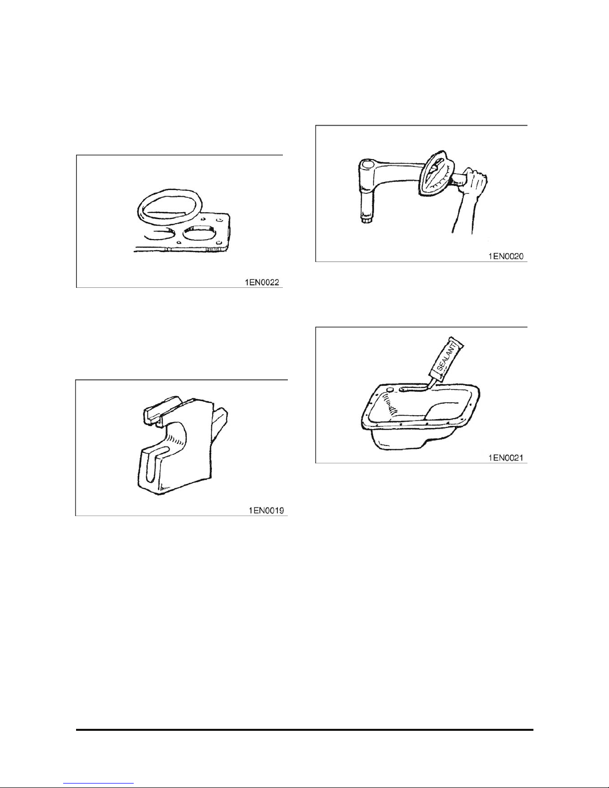
Replacement Part
When oil seal, O-ring, pac k ing and gas k et have
been removed, be sure t o replace t hem with new
parts.
However, rocker cover gasket may be reused if it is
not damaged.
Rubber Parts
Do not stain timing belt and V- belt with oil or water.
Therefore, do not clean the pulley and sprocket with
detergent.
Oil and Grease
Before reassembly , apply s pec ified oil to the rotating
and sliding parts.
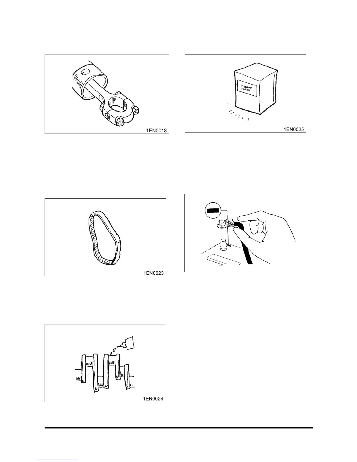
Genuine Part
When the part is to be replaced, be s ur e to use
genuine part.
For selection of appropriate parts, refer to the Parts
Catalog.
Electrical System
1. Be sure to disconnect the bat tery cable from the
negative (-) terminal of the battery.
2. Never pull on the wires when dis c onnec ting
connectors.
3. Locking connector s will c lic k when the connector
is secure.
4. Handle sensors and relays c ar efully. Be careful
not to drop them or hit them against other parts.
Page 11

G424F(FE) Servi ce Manual Chapter 1. General Info rmat ion 9
Precautions for catalytic Converter
CAUTION
If a large amount of unburned gasoline flows
into the con verter, it may overheat and create a
fire hazard. To prevent this, observe the
following precau tions and explain them to your
customer.
1. Use only unleaded gasoline.
2. Do net run the engine while the tr uc k is at rest f or
a long time. Avoid running the engine at fast idle
for more than 5 minutes and at idle speed for
more than 10 minutes.
3. Avoid spark-jum p tests. Do spark-jumps only
when absolutely necessary . Perform this test as
rapidly as possible and, while t es ting, never race
the engine.
4. Do not measure engine compress ion for an
extended time. E ngine c om pr es s ion tests must be
made as rapidly as possible
5. Do not run the engine when the fuel tank is nearly
empty. This may cause the engine to m is fire and
create and extra load on the conv er ter.
6. Avoid coasting with the ignition turned off and
during prolonged braking
7. Do not dispose of a used catalyt ic c onv erter
together with parts contaminated with gasoline or
oil.
Page 12
G424F(FE) Servi ce Manual Chapter 1. General Info rmat ion 10
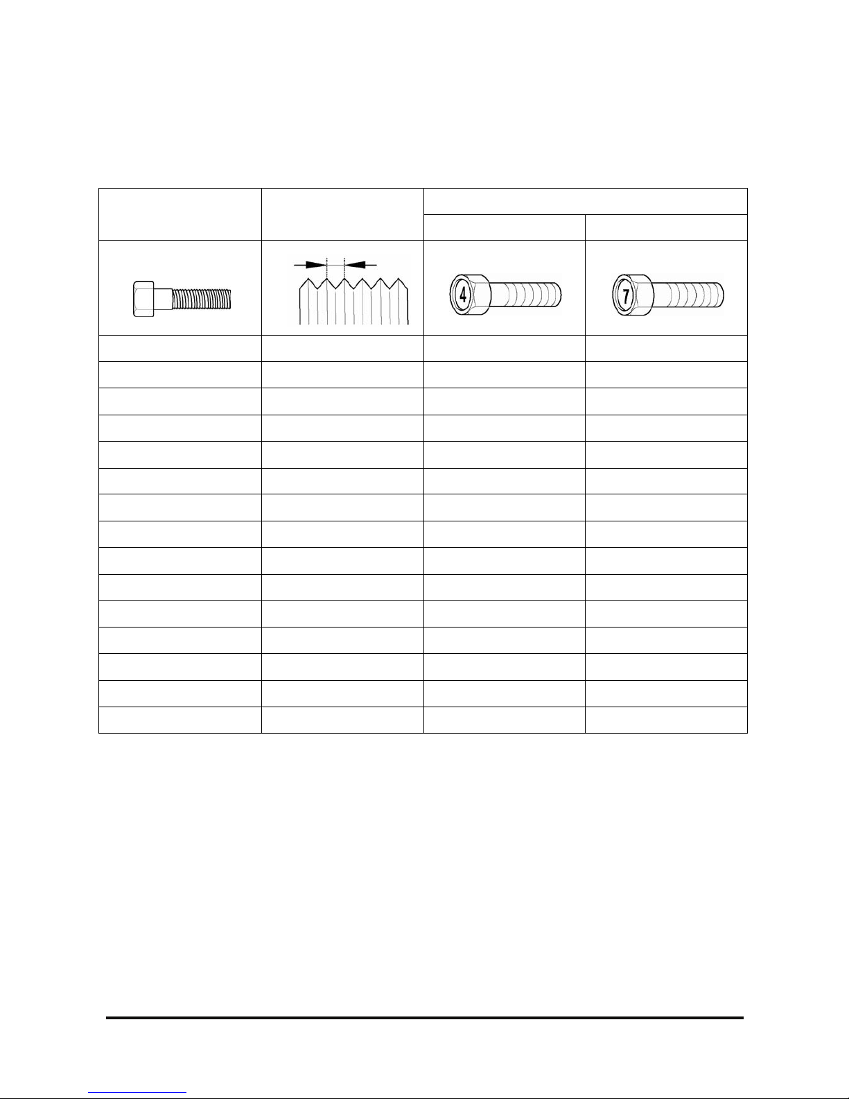
Tighteni ng Torque
Tightening Torque Table of Standard Parts
Torque (kg·m)
Bolt nominal diameter
(mm)
Pitch (mm)
Head mark 4 Head mark 7
M5 0.8 0.3 ~ 0.4 0.5 ~ 0.6
M6 1.0 0.5 ~ 0.6 0.9 ~ 1.1
M8 1.25 1.2 ~ 1.5 2.0 ~ 2.5
M10 1.25 2.5 ~ 3.0 4.0 ~ 5.0
M12 1.25 3.5 ~ 4.5 6 ~ 8
M14 1.2 7.5 ~ 8.5 12 ~ 14
M16 1.5 11 ~ 13 18 ~ 21
M18 1.5 16 ~ 18 26 ~ 30
M20 1.5 22 ~ 25 36 ~ 42
M22 1.5 29 ~ 33 48 ~ 55
M24 1.5 37 ~ 42 61 ~ 70
M5 0.8 0.3 ~ 0.4 0.5 ~ 0.6
M6 1.0 0.5 ~ 0.6 0.9 ~ 1.1
M8 1.25 1.2 ~ 1.5 2.0 ~ 2.5
M10 1.25 2.5 ~ 3.0 4.0 ~ 5.0
NOTE: The torques shown in t he table are s tandard
vales under the following conditions.
1. Nuts and bolt are made of steel bar and
galvanized.
2. Galvanized plain st eel was her s ar e ins er ted.
3. All nuts, bolts, plain washer s ar e dr y .
NOTE: The torques shown in t he table are not
applicable,
1. When spring washers, toothed washers and the
like are inserted.
2. If plastic parts ar e fastened.
3. If oil is applied to thr eads and s urfac es .
NOTE: If you reduce the tor ques in the t able to the
percentage indicated below under the following
conditions, it will be the standard value.
1. If spring washers ar e us ed : 85%
2. If threads and bearing s ur faces are stained with
oil: 85%
Page 13

G424F(FE) Servi ce Manual Chapter 1. General Info rmat ion 11
Recommended Lubric a nt s and Capaciti e s
Recommended Lubricants
Lubricant Specification Remarks
Engine Oil API Classification SJ or above SAE 10W30 or SAE 5W30
Coolant (Antifr eez e)
Automotive ant ifreeze
suitable for gasoline engines
having aluminum alloy parts
Concentration level 50%(nor m al)
Concentration level 40%(tropical)
Lubricant Capacities
Description G(C)20/25/30/33P-5
Oil Pan 4.25
Oil Filter 0.3
Engine Oil (liters)
Total 4.5
Engine 3.0
Radiator & Hoses 6.0
Coolant (liters)
Total 9.0
Page 14
G424F(FE) Servi ce Manual Chapter 1. General Info rmat ion 12
Engine Model and Engine Serial
Number
Engine
Model
Fuel Type
Emission
Regulation
G424FE LP/Dual Fuel
EPA/CARB*
2007
Compliant
G424F LP
* EPA: Environmental Protection Agency
* CARB: California Air Resources Board
G424FE Engine
• Comply with EPA 2007 Emission Regulation
• Electronic Cont r ol by ECM
• Certified LP/ Dual Fuel Sy s tem available
– Closed loop LP Carburetion system
– Closed loop MPI Gasoline system
• 3-way Catalytic Muffler is standard
G424F Engine
• Not comply with EPA 2007 Emiss ion Regulation
• Electronic Cont r ol by ECM
• Standard LP System available
– Open loop LP Carburetion s y stem
• Muffler is standard
Indication of Engine Model and Serial
Number
Engine Model Engine Serial Number
G424FE/G424F 30700001 to 39999999
Features and Benefi t s of G424F E/G424F Engine
• Al head with valve seat inserts
– Aluminum head and valve seat s yst em
• SOHC 8 valve system
• Timing belt system
• Distributorles s Ignition system
• Electronic control system by ECM (Engine control
module)
– Drive-by-wire system
– Higher efficiency and lower fuel consumption
– Min./Max. gover nor c ontrol
– Automatic engine protec tion from overheating
and/or low engine oil pressure
– Automatic trans m is s ion pr otection from
overheating
– Engine diagnostics by ser v ic e-tool software
– Forklift ground speed lim it (optional)
Page 15

G424F(FE) Servi ce Manual Chapter 1. General Info rmat ion 13
General Specification
G424FE Engine G424F Engine
GENERAL DESCRIPTION
ENGINE TYPE: Water-cooled, Inline 4-Cy c le, 4-Cylinders
COMBUSTION SYSTEM: Squish Combution Chamber
INTAKE MANIFOLD Cast Aluminum (wit h injec tor ports)
EXHAUST MANIFOLD Cast Iron (dual channel)
VALVE CONFIGURATION: SOHC, 2 Valves per Cylinder
VALVE LIFTER/LAS H ADJUSTER Stationary Hydraulic Lash Adjus ters
VALVE ROTATOR Exhaust Rotat or
CAMSHAFT DRIVE Timing belt system ( 20 mm Toothed B elt)
DISPLACEMENT: 2,405 cc (147 cid)
BORE x STROKE 87 mm (3.44 in) x 100 mm (3.94 in)
BLOCK STRUCTURE Grey Cast Iron
HEAD STRUCTURE Aluminum with seat ins er ts
COMPRESSION RATIO: 9.6:1
COMPRESSION PRESSURE: 1,240 kPa (180psi) Minim um
Intake Valve: 17°30' B TDC/ 76°30' ABDC
VALVE TIMING:
Exhaust Valve: 58°30' B B DC/ 35° 30' ATDC
FIRING ORDER: 1-3-4-2
WEIGHT: 120 kg
ENGINE ROTATION: Counter-Clockwise (CCW) when viewed from Flywheel End
FUEL TYPE: LPG, Dual Fuel (LPG or Gasoline)
CRANK VENTILATION Foul Air System with PCV
IGNTION SYSTEM
IGNITION TYPE: Distributorless (waste spark)
IGNITIOIN TIMI NG: Electronic controlled by E CM
IGNITION COIL: 12 V operation volt
SPARK PLUGS: 0.035" (0.8-0.9 mm) Air Gap
LUBRICATION SYSTEM
OIL PRESSURE: 282 - 324 kPa @ 1400 rpm
OIL TEMPERATURE:
Upper Limit: 125 °C (257°F )
Recommended: 99 – 110 °C (210 - 230°F)
Lower Limit:80 °C ( 176 °F)
OIL PAN Cast Aluminum
OIL PAN CAPACITY 4.25 L (EXCLUDES OIL FILTE R)
OIL FILTER: 0.3 L
ENGINE OIL SPECIFICATION: API - SJ, SAE 10W30 or SAE 5W30
Page 16

G424F(FE) Servi ce Manual Chapter 1. General Info rmat ion 14
G424FE Engine G424F Engine
COOLING SYSTEM
WATER PUMP ROTATION: Toothed Timing Belt Driv e- Cloc k wis e from front of engine
THERMOSTAT:
Opening Temperatur e: 82°C (180°F)
Fully Open Temperatur e: 95°C (203°F)
COOLING WATER CAPACITY: 3.0 L
LP FUEL SYS TEM
LP FUEL SYSTEM
Closed loop LP Carburetion
System
Open loop LP Carburetion
System
MIXER:
Diaphragm Type Air Valv e
Assembly inside, Downdr aft
(Model: CA-100)
Diaphragm Type Air Valv e
Assembly inside, Downdr aft
(Model: CA-100)
REGULATOR:
Two-Stage Negativ e P r es s ur e
Regulator (Model: N-2007)
Two-Stage Negativ e P r es s ur e
Regulator (Model: N-2001)
FUEL TRIM VALVE (FTV): Dual Dither System None
FUEL FILTRATION: 40 Microns Maximum 40 Microns Maximum
GASOLINE FUEL SYSTEM
GASOLINE FUEL SYSTEM Closed loop MPI System and In-Tank Fuel Pump System
Electric Fuel P ump (12V)
Fuel Filter & Strainer
FUEL PUMP MODULE
Gasoline Pressure Regulator (3.5 bar)
FUEL INJECTOR ASS’Y Electric Fuel Injector (12V)
ENGINE ELECTRIC
ENGINE CONTROL
MODULE(ECM):
12 V operation volt, 48 pins of I/O
CRANK SENSOR VR (Variable Reluctanc e)
CAM SENSOR Hall sensor (Dual fuel engine only)
TMAP: Intake Air Temp. & Manifold Absolute Press. Sensor
PEDAL ANGLE SENSOR: Two-O utput Signals (Installed on Accelerator Pedal)
OXYGEN SENSOR: Dual O x y gen S ens or S yst em None
ECT-ECM: Engine Coolant Temperat ur e S ens or for ECM
ECT-GAUGE Engine Coolant Temp. Sens or for GAUGE on Instrument Panel
TPS: Throttle Position Sens or ( built in Throttle Body)
THROTTLE BODY: Electronic Throttle Body
LP FUEL LOCK-OFF: 12 V operation volt
ENGINE OIL PR. S/W: 14-41 kP a
STARTING MOTOR: 12 Volts, 1.4 kW
ALTERNATOR: 13.5 Volts, 80 A
EXHAUST SYSTEM
Muffler Catalytic M uff ler Muffler (wit hout catalyst)
Page 17

G424F(FE) Servi ce Manual Chapter 1. General Info rmat ion 15
G424F/G424FE Engine Power and Torque
G424FE G424F
ENGINE MODEL unit
G424FE-LP
G424FE-DF(LP)
G424FE-DF(GAS) G424F-LP
kW 46.2 44.7 46.2
hp 62 60 62
PS 62.9 60.8 62.9
RATED POWER
rpm 2,550 2,550 2,550
N-m 181 172 181
ibf-ft 134 127 134
Kgf-m 18.5 17.5 18.5
MAX TORQUE
rpm 2,200 2,200 2,200
GOVERNED SPEED rpm 2,600 2,600 2,600
LOW IDLE rpm 750 750 750
Page 18
G424F(FE) Servi ce Manual Chapter 2. Recommended Maintenance 16
Chapter 2. RECOMMENDED MAINTENANCE
Suggested maintenance r equir em ents for an engine equipped with an MI-07 fuel sy stem ar e contained in this
section. The oper ator should, however, develop a customized maintenance schedule using the requirements
listed in this section and any other requirements listed by the engine manufac turer.
General Mainte na nc e
Test Fuel System for Leaks
• Obtain a leak check squirt bot tle or pump spray
bottle.
• Fill the bottle with an approved leak check solution.
• Spray a generous amount of the solution on the
fuel system fuel lines and connections, start ing at
the storage cont ainer .
• Wait approximately 15-60 seconds, then perform a
visual inspection of the fuel system. Leaks will
cause the solution t o bubble.
• Listen for leaks
• Smell for LPG odor which may indic ate a leak
• Repair any leaks before c ontinuing.
• Crank the engine through s ev er al revolutions. This
will energize the fuel lock- off and allow fuel to
flow to the pressure regulator/converter. Apply
additional leak check s olution to the regulator/
converter fuel c onnec tions and housing. Repeat
leak inspection as list ed abov e.
• Repair any fuel leaks bef or e c ontinuing.
Inspect Engine for Fluid Leaks
• Start the engine and allow it to reac h oper ating
temperatures.
• Turn the engine off.
• Inspect the entir e engine for oil and/or coolant
leaks.
• Repair as necessary before continuing.
Inspect Vacuum Lines and Fittings
• Visually inspect v ac uum lines and fittings for
physical damage such as brittleness, cracks and
kinks. Repair/r eplac e as r equir ed.
• Solvent or oil damage may caus e v ac uum lines t o
become soft, resulting in a collapsed line while
the engine is running.
• If abnormally soft lines ar e detected, replace as
necessary.
Inspect Electrical System
• Check for loose, dirt y or dam aged c onnec tors and
wires on the harness including: fuel lock-off,
TMAP sensor, O2 sensors, elec tronic throttle,
control relays, fuel t r im valves, crank position
sensor, and cam position sensor.
• Repair and/or replace as nec es s ary.
Inspect Foot Pedal Operation
• Verify foot pedal t r av el is smooth without sticking.
Page 19

G424F(FE) Servi ce Manual Chapter 2. Recommended Maintenance 17
Engine Oil Classification
Recommended API clas s ification: Above SJ
Recommended SAE viscosity classification
The following lubricants s hould be s elec ted for all
engines to enhance excellent per formance and
maximum effect.
1. Observe the API classif ic ation guide.
2. Proper SAE classification number should be
selected within ambient temperature ranges. Do
not use the lubricant with SAE classification
number and API grade not identified on the
container.
*1. 10W-30 engine oil is recom m ended
If 10W-30 is not applicable, pr oper engine oil will be possible according to temperat ur e r anges .
Page 20
G424F(FE) Servi ce Manual Chapter 2. Recommended Maintenance 18
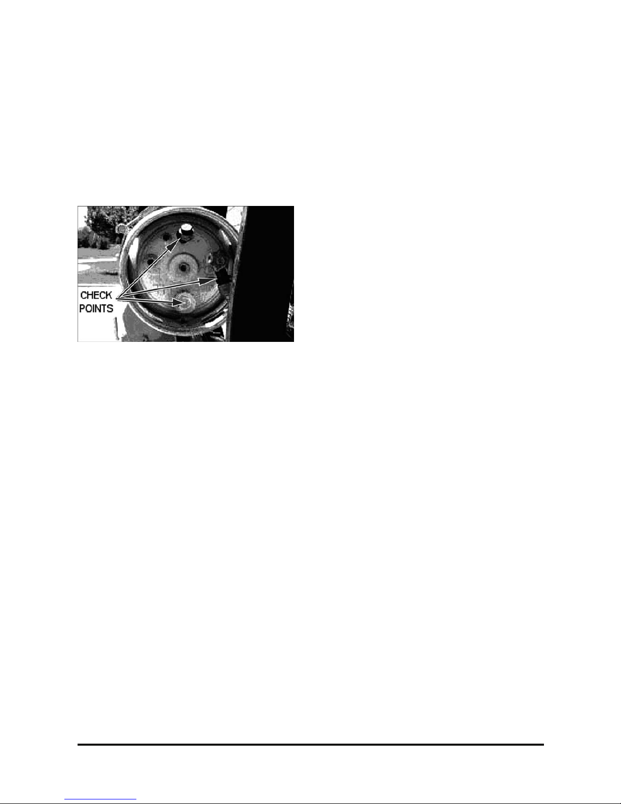
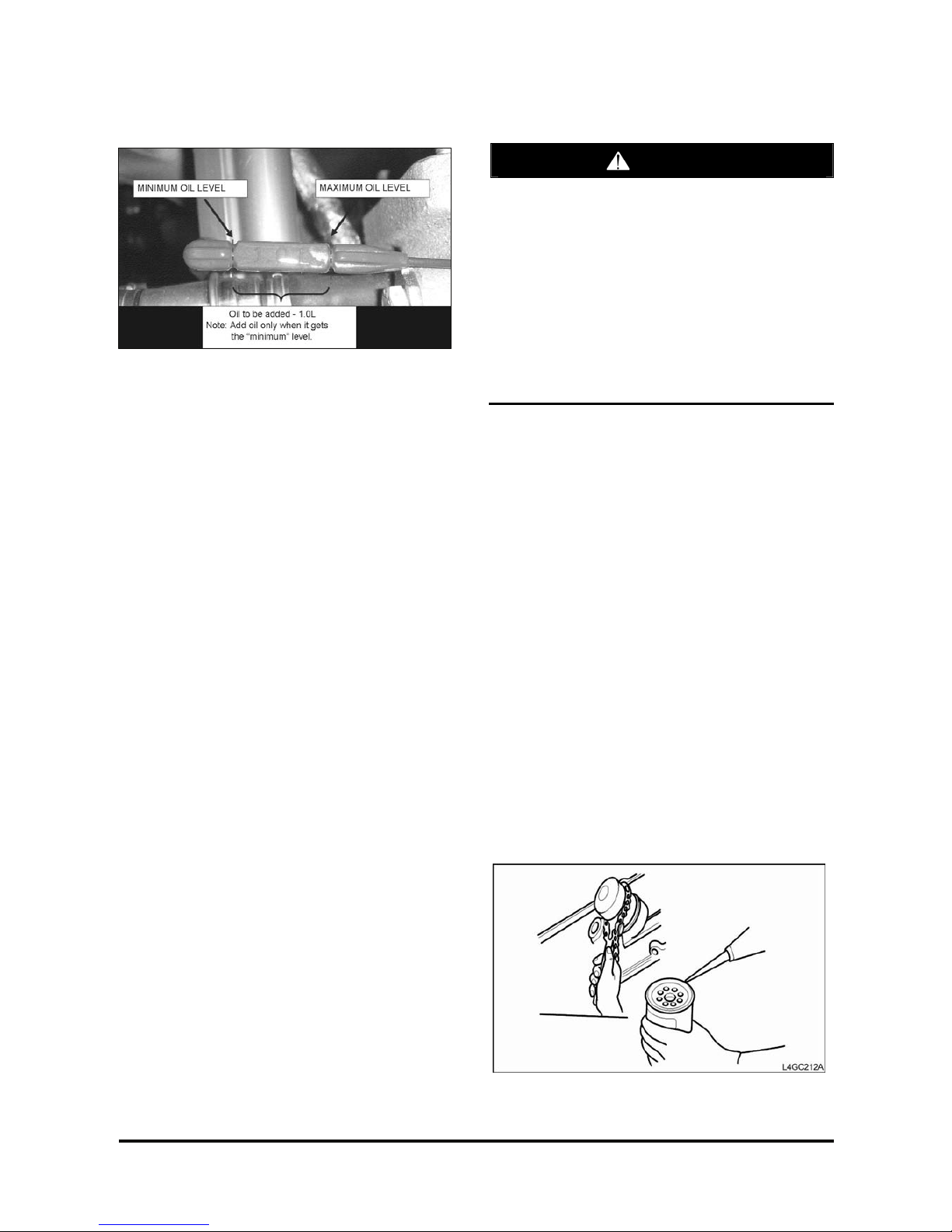
Checking Engine Oil Level
1. Check that the oil level is between “MIN” and
“Max” marks on the engine oil level gauge.
2. If the oil level is below “MIN” m ark, add oil until
the level is within the s pec ified ranges.
3. Check the engine for oil cont am ination and
viscosity and replac e if necessary.
Replacing Engine Oil and Filter
CAUTION
Prolonged and repeated contact with mineral oil
will result in the removal of natural fats from the
skin, leading to dryness, irri tation and dermat itis.
In addition, used engine oil contains potentially
harmful contaminants which may cause skin
cancer.
Exercise caution in order to minimize the leng th
and frequency of contact of your skin to used oil.
In order to preserve the environment, used oil
and used oil filter must be disposed of only at
designated di sposal sites.
1. Drain engine oil.
1) Remove the oil filler c ap.
2) Remove the oil drain plug, and dr ain the oil into
a container.
2. Replace oil filter.
1) Remove the oil filt er.
2) Check and clean the oil filter installation
surface.
3) Check the part number of the new oil filter is as
same as old one.
4) Apply clean engine oil to the gas k et of a new
oil filter.
5) Lightly screw t he oil filt er into place, and
tighten it until the gasket contacts the seat.
6) Tighten it an additional 3/4 turn.
Page 21
G424F(FE) Servi ce Manual Chapter 2. Recommended Maintenance 19
3. Refill with engine oil filter.
1) Clean and install the oil drain plug wit h a new
gasket.
Torque 40~70 N·m
2)Fill with fres h engine oil.
Capacity Drain and refill 4.3 L
Oil filter 0.3 L
3) Install the oil filler c ap.
4. Start engine and check for oil leaks.
5. Recheck engine oil level.
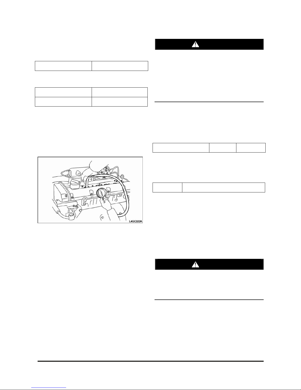
Checking Compressed Pressure
1. Prior to inspection, check that the engine oil,
starter motor and batt er y are normal.
2. Start the engine and run it unt il the engine coolant
temperature reac hes 80 ~ 95° C.
3. Stop the engine and disconnect the ignition coil
and air cleaner element.
4. Remove the spark plug.
5. After opening the t hr ott le v alv e c om pletely, crank
the engine to remove f or eign m aterial from the
cylinder.
CAUTION
At this time, necessarily screen the spark plug
hole with a rag. Because hot coolant, oil, fuel,
and other foreign material, being penetrated in
the cylinder through cracks can come into the
spark hole during checking compressed
pressure.
When cranking the engine to test compressed
pressure, necessaril y open the throttle valve before cranking.
6. Install the compr es s ion gauge to the spark plug
hole.
7. With the thrott le valve opened, c r ank the engine
to measure the compress ed pr es s ure.
Standard (250~400 r pm ) Limit 1,240 kPa
8. Repeat steps ( no.6-7) over all c ylinders, ensur ing
that the pressure differential for each of the
cylinders is within t he lim it.
Limit 100 kP a ( between cylinders)
9. If any of all cylinders is out of lim it, add a small
amount of engine oil to t he spark plug hole, and
re-proceed the procedur es ( no.6-7) to the cylinder.
At this time, if the compressed pressur e is increased,
it means that the piston, pis ton ring or cylinder
surface are worn or damaged, and if the
compressed pressur e is dec r eas ed, it means that
the valve is clogged, the valve contact is faulty, or
the pressure leaks through gasket.
CAUTION
If a large amount of incomplete combustion
gasoline comes into the catalytic converter,
emergency such as a fire can occur due to
overheating. So this job should be done quickly
with the engine not operated.
Page 22
G424F(FE) Servi ce Manual Chapter 2. Recommended Maintenance 20
Cooling System Mai ntena nc e
Coolant Recommendation
The engine cooling system is provided with a
mixture of 50% ethylene glyc ol anti-freeze and 50%
water (For the vehicles of t r opic al area, the engine
cooling system is provided with a mixture of 40%
ethylene glycol anti-freeze and 60% water at the
time of manufactur e.)
Since the cylinder head and wat er pum p body ar e
made of aluminum alloy casting, be sure to use a 30
to 60% ethylene glycol ant ifreeze coolant to assure
corrosion protection and freezing prevention.
CAUTION
If the concentration of the antifreeze is below
30%, the anticorrosion property will be adversely
affected. In addition, if the concentration is
above 60%, both the antifreeze and engine
cooling properties will decrease, adversely
affecting the engine. For th ese reasons, be sure
to maintain the concentration level within the
specified range.
Coolant Water
Hard water, or water wit h high lev els of calc ium and
magnesium ions, encourages the formation of
insoluble chemical compoun ds by c om bining with
cooling system additives such as silicates and
phosphates.
The tendency of silicat es and phos phates to
precipitate out- of-solution increases with increasing
water hardness. Har d water, or water with high
levels of calcium and magnes ium ions enc our ages
the formation of insoluble c hem ic als , especially after
a number of heating and cooling cycles.
DOOSAN prefers the use of distilled water or
deionized water to reduce the potential and severity
of chemical insolubility .
Acceptable Water
Water Content Limits (ppm)
Chlorides (CI) 40 maximum
Sulfates (SO4) 50 maximum
Total Hardness 80mg/ℓ maximum
Total Solids 250 maximum
pH 6.0 ~ 8.0
ppm = parts per million
Antifreeze
DOOSAN recommends select ing automotive
antifreeze suit able for gasoline engines using
aluminum alloy parts. The antifreeze should meet
ASTM-D3306 standard.
Check Coolant Level
• The items below are a general guideline f or
system checks. Refer to the engine
manufacturer’s s pec ific recommendations for
proper procedures.
• Engine must be off and cold.
WARNING—PROPER USE
Never remove the pressu re cap on a hot engin e.
• The coolant level should be equal to the “COLD”
mark on the coolant recover y tank.
• Add approve coolant t o the spec ified level if the
system is low.
Inspect Coolant Hoses
• Visually inspect c oolant hoses and clamps.
Remember to check the two coolant lines that
connect to the pressur e r egulator/converter.
• Replace any hose that shows signs of leakage,
swelling, cracking, abr as ion or deterioration.
Page 23
G424F(FE) Servi ce Manual Chapter 2. Recommended Maintenance 21
Checking coolant leaks
1. After the coolant t em per ature drops below 38°C
loosen the radiator cap.
2. Check that the coolant level r eac hes filler neck.
3. Install the radiat or c ap tester to the radiator filler
neck and apply a pressure of 1.4kg/cm2 .
While maintaining it f or 2 m inutes, check the radiator,
hose, and connecting part for leak.
CAUTION
Because the coolant in the radiator is too hot,
never open the cap when it hot, or injury may
occur due to an outburst of hot water.
Dry out the inspection p art .
When removing th e tester, take care not to spill
the coolant.
When removing/installing the tester as well as
testing, take care not to deform the fille r neck.
4. Replace parts if leak is detected.
Specific gravity test
1. Measure specif ic gravity of the coolant using a
hydrometer.
2. After measuring the coolant temperature,
calculate specific gr av ity using the following table.
Relation between Coolant concentration and Specific Gravity
Temperature and Sp ecific gravity of coolant (Temp.:℃)
10 20 30 40 50
Freezing
temp(℃)
Coolant Concentration
Specific Volume
1.054 1.050 1.046 1.042 1.036 -16 30%
1.063 1.058 1.054 1.049 1.044 -20 35%
1.071 1.067 1.062 1.057 1.052 -25 40%
1.079 1.074 1.069 1.064 1.058 -30 45%
1.087 1.082 1.076 1.070 1.064 -36 50%
1.095 1.090 1.084 1.077 1.070 -42 55%
1.103 1.098 1.092 1.084 1.076 -50 60%
Page 24
G424F(FE) Servi ce Manual Chapter 2. Recommended Maintenance 22
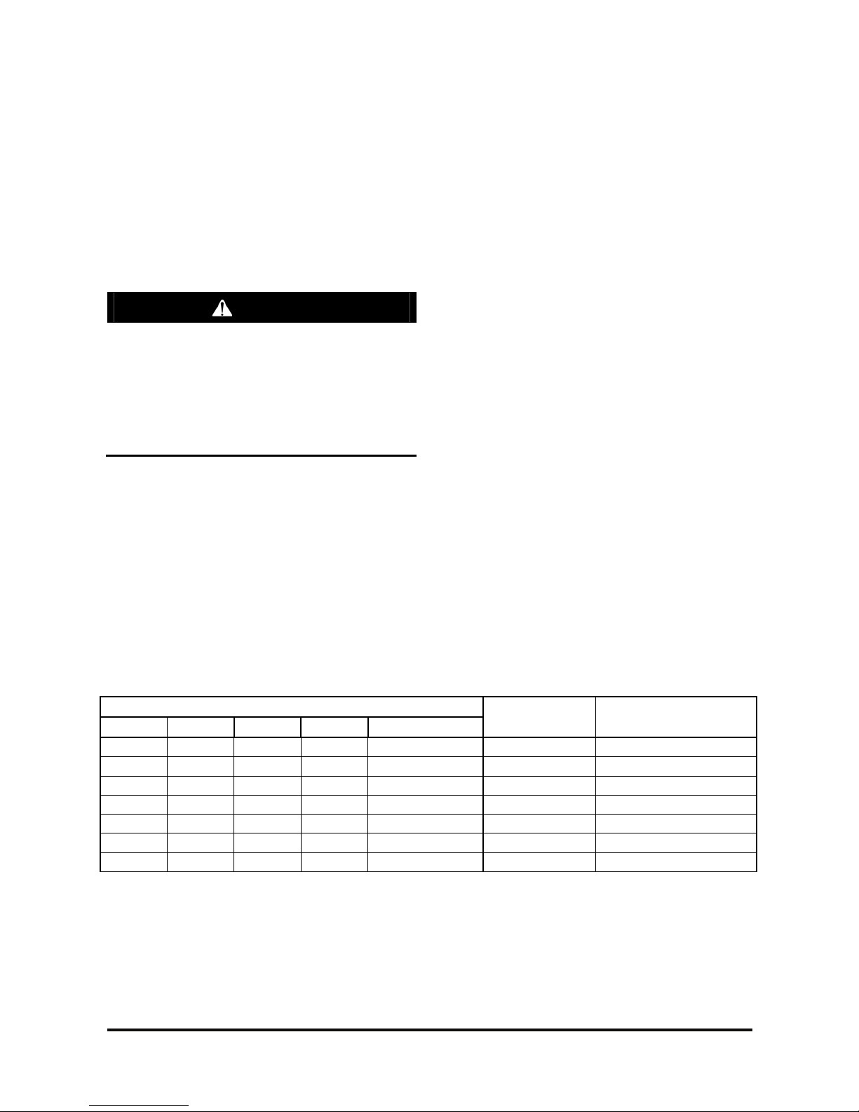
Checking and Adjusting Drive Belt
1. Checking tension
1) Press the middle of the water pum p pulley and
alternator pulley wit h 10k gf.
2) Inspect the belt deflection by pressing it.
3) If the belt deflection is out of the standard,
adjust it as follows.
Standard
Item
New belt Used belt
Drive belt deflect ion ( L) 4.0~4.4mm 5.1~ 5.7mm
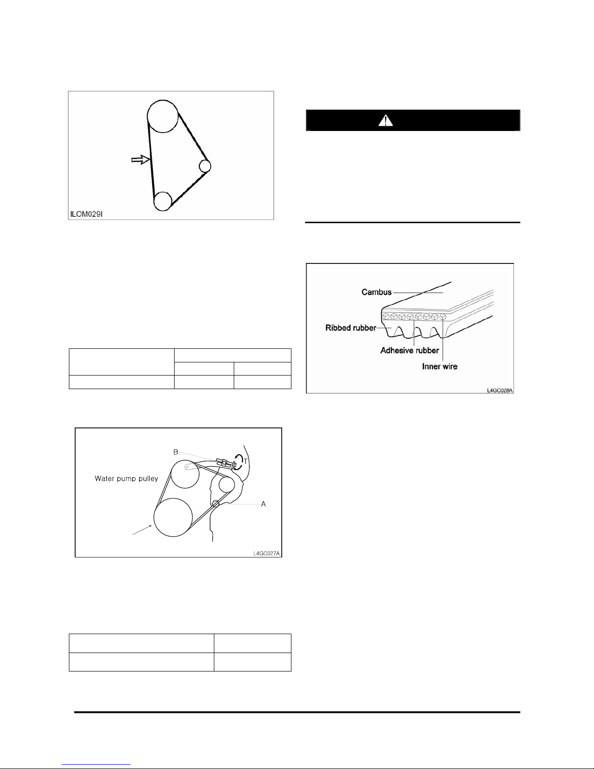
Adjusting
1. Loosen the alternator support bolt “A” nut and
adjusting lock bolt “B ” .
2. Adjust the belt tension by m ov ing the alternator
brace adjusting bolt t o “ T” dir ec tion.
Alternator adjusting lock bolt “B” 1.2~1.5kg·m
Alternator suppor t bolt “A” 2~2.5kg·m
3. Tighten the bolt “A ” and then tighten “B” to the
specified torque.
CAUTION
If the belt tension is too excessive, noise as well
as early wear of belt occurs and the water pu mp
bearing and altern at or bearing are damaged.
If the belt is too loose, due to early wear of belt
and insufficient power of alternator, battery and
water pump become inefficient and finally
engine is over he ated or dama ged.
Checking Belt for Damage
Check the following item s and r eplac e the belt if
defective.
1. Check the belt surf ac e for dam age, wear and
crack.
2. Check the belt surf ac e for oil or grease
contamination.
3. Check the rubber part for wear or hardening.
4. Check the pulley surfac e for crack or damage.
Crank
pulley
Page 25

G424F(FE) Servi ce Manual Chapter 2. Recommended Maintenance 23
Ignition Syst em Mai nt e nance
Inspect Battery System
• Clean battery out er surfaces with a mixture of
baking soda and water.
• Inspect batter y outer surfaces for damage and
replace as necessary.
• Remove battery cables and c lean, repair and/or
replace as necessary.
Inspect Ignition System
• Remove and inspect the spark plugs . Replace as
required.
• Inspect the ignition coil for cracks and heat
deterioration. V is ually ins pec t the coil heat sink
fins. If any fins are br oken replace as requir ed.
Inspection of Ignition Timing
1. Inspection c ondition
Coolant temperatur e : 80-90°C(At normal
Temperature)
Lamp and all accessories : OFF
Transmission : In neutral position
Parking brake : ON
2. Inspection
1) Connect the timing light.
2) Measure RPM.
RPM
Low Idle 750±15rpm
NOTE: If RPM is not normal, it is impos s ible to
measure the proper ignit ion timing, so measure it at
a normal RPM.
3) Inspect the standard ignit ion timing.
BTDC 5˚±5˚
4) If ignition timing is out of the standard, inspect
sensors concerned wit h ignition timing.
CAUTION
Because ignition timing is fixed by set data
value in ECU, it is impossible to control on
purpose.
Fist, check that sensors send output properly to
help determine ignition timing control.
NOTE: Affectiv e ECU input to Ignition timing control
• Coolant temperat ur e s ens or
• Oxygen sensor
• Battery voltage
• MAP sensor (Engine load)
• Crankshaft position s ens or
• Throttle position s ens or
• Intake Air Temperature sensor
5) Check that actual ignit ion timing is changed
with engine RPM increased.
Page 26
G424F(FE) Servi ce Manual Chapter 2. Recommended Maintenance 24
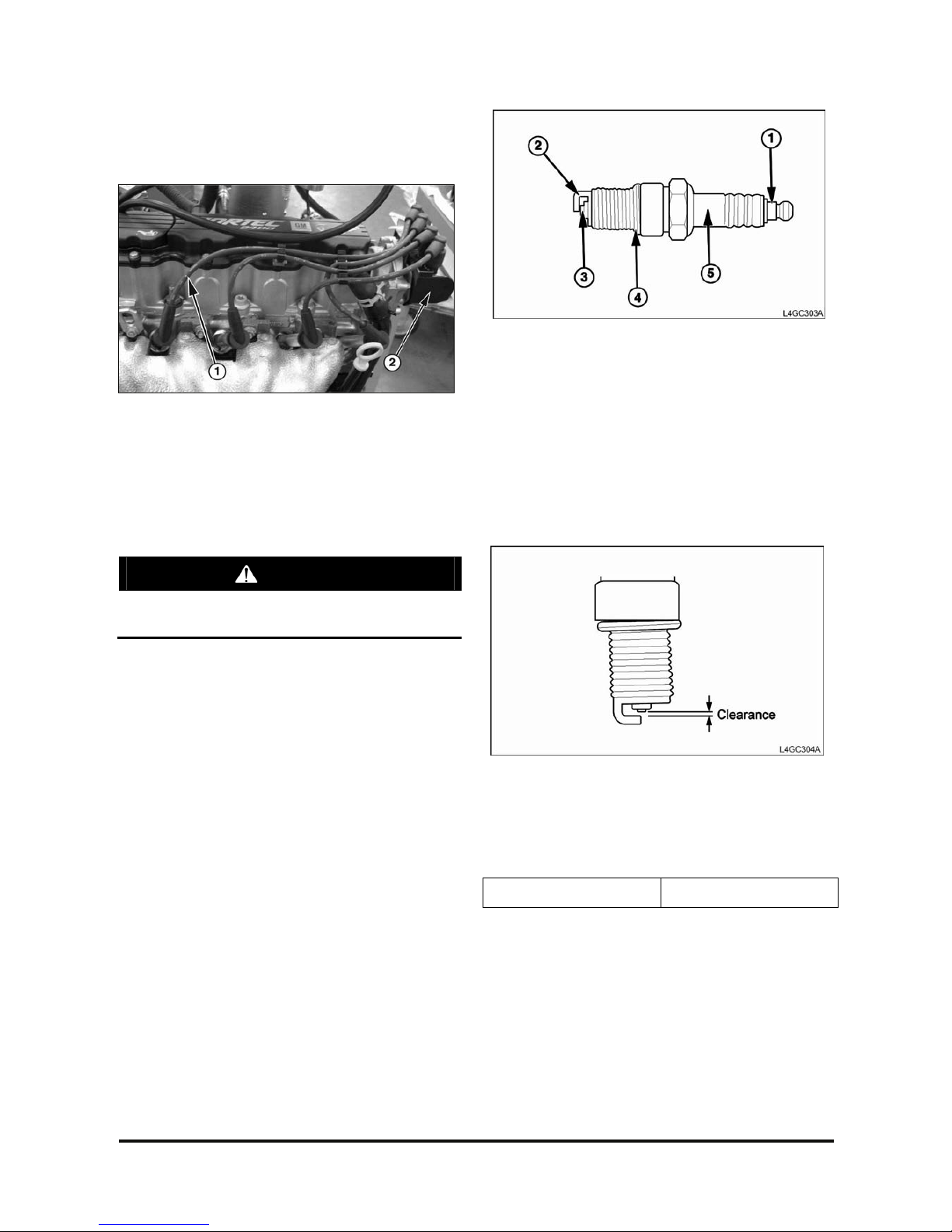
Inspection of Spark Plug
Inspection and clean
1) Ignition cable
2) Ignition coil
1. Disconnect t he ignition cables from ignition coil
ass’y.
2. Remove all spark plugs from the cy linder head
using a sparkplug wrench.
CAUTION
Take care not to come foreign materials into
spark-plug mounting hole.
3. Check the spark plug as below.
1) Insulator brok en
2) Terminal worn
3) Carbon deposit
4) Gasket damaged or broken
5) Porcelain insulator of spark plug clearance
4. Check the plug clearance using a plug clear anc e
gauge and if the value is not within the specified
values, adjust it by bending the gr ound c lear anc e.
When installing a new sparkplug, install it after
checking the uniform plug c lear anc e.
Spark plug clearance 0.8~0.9mm
Page 27
G424F(FE) Servi ce Manual Chapter 2. Recommended Maintenance 25
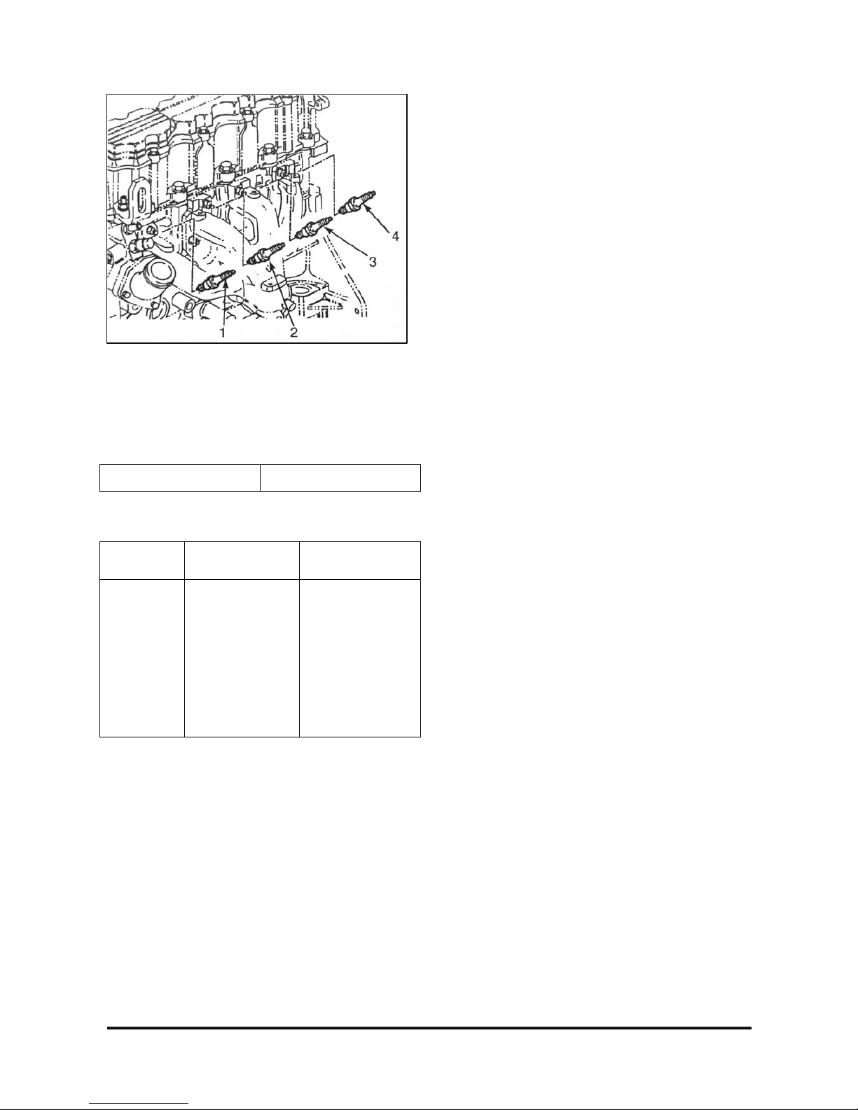
Spark Plugs
5. Install the spark plug and tighten it to the specified
torque.
Take care not to over tight en it t o pr ev ent cy linder
head threads from dam age.
Tightening torque 2 ~ 2.5 kg·m
SPARK PLUG ANALYSIS
State
Contact point is
black
Contact point is
white
Description
• Density of the
fuel mixture is
thick
• Density of the
fuel mixture is
thin
• Lack of air
intake
• Ignition timing is
fast
• Spark plug is
tight
• Lack of torque
Page 28
G424F(FE) Servi ce Manual Chapter 2. Recommended Maintenance 26
Fuel System Maintena nc e
Replace LP Fuel Filter Element
Park the lift truck in an authorized refueling area with
the forks lowered, park ing br ak e applied and the
transmission in Neut r al.
1. Close the fuel shutof f valv e on the LP-fuel tank.
Run the engine until the fuel in the system runs
out and the engine stops.
2. Turn off the ignition switch.
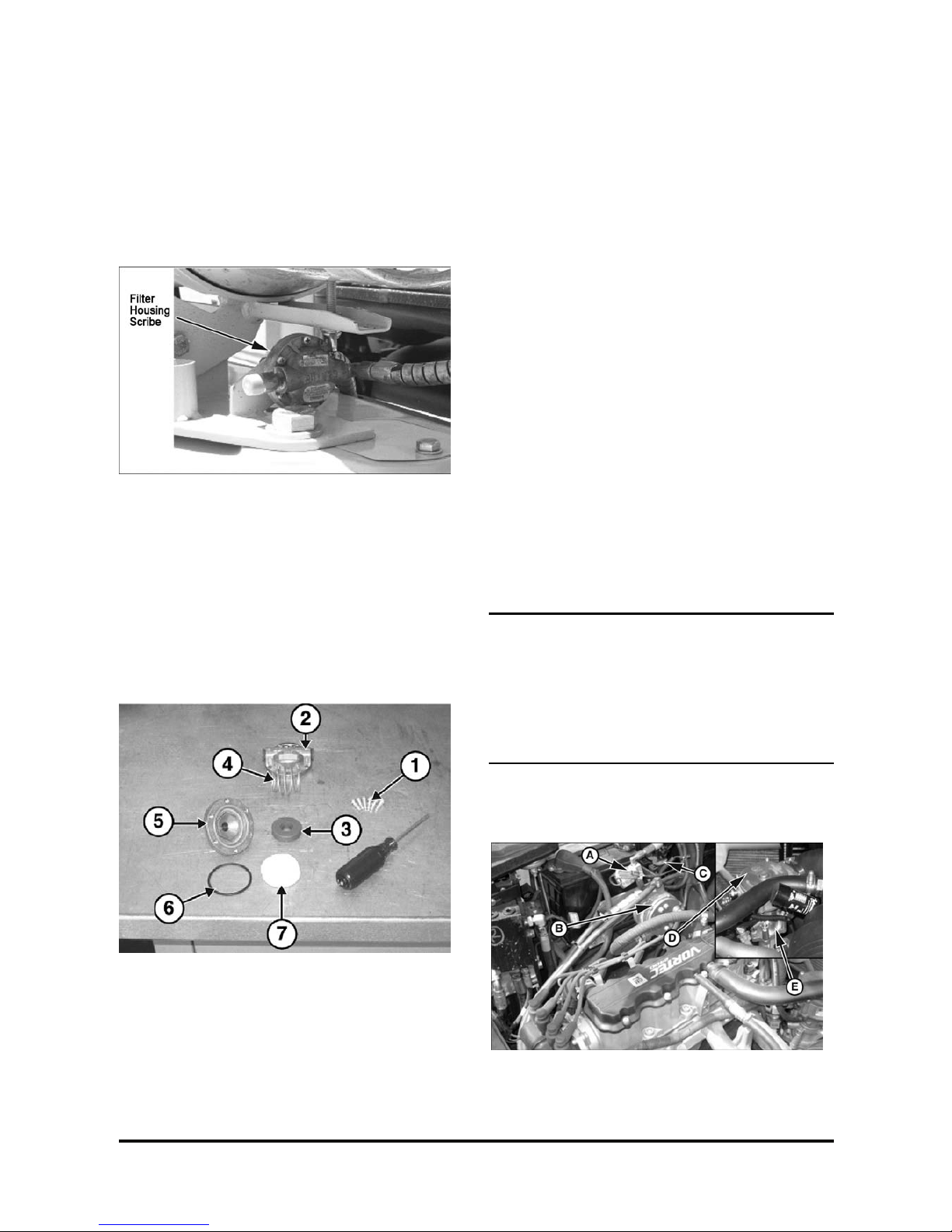
3. Scribe a line across the filt er hous ing c ov er s ,
which will be used for alignment pur pos es when
re-installing the f ilter cover.
FUEL FILTER DISASSEMBLY (Steps 4-7)
4. Remove the cover retaining screws (1).
5. Remove top cover (2), magnet (3), spring (4), and
filter element ( 7) from bottom cover (5).
6. Replace the filt er elem ent (7) .
7. Check bottom cover O- r ing s eal ( 6) f or damage.
Replace if necessary.
8. Re-assemble the filt er as s em bly aligning the
scribe lines on the top and bott om c ov er s.
9. Install the cover r etaining sc r ews , tightening the
screws in an opposite sequenc e ac r os s the cov er .
10. Open the fuel valve by slowly t ur ning the valve
counterclockwise.
11. Crank the engine sever al r ev olutions to open the
fuel lock-off. DO NOT START THE ENGINE.
Turn the ignition key s witch to the off position.
12. Check the filter hous ing, fuel lines and fittings for
leaks. Repair as necess ar y .
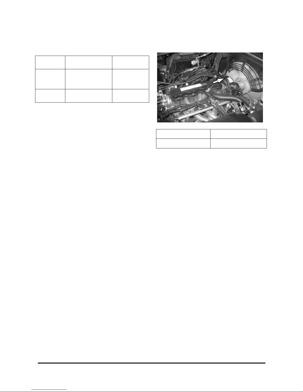
Testing Fuel Lock-off Operation
• Start engine.
• Locate the electrical c onnector for the fuel lock (A) .
• Disconnect the elec tric al c onnec tor.
• The engine should run out of fuel and s top within a
short period of time.
NOTE
The length of time the engine runs on trapped fuel
vapor increases with any increase in distance
between the fuel lock-off and the pressure
regulator/converter.
• Turn the ignition key switch off and re-connect the
fuel lock-off connect or .
Page 29

G424F(FE) Servi ce Manual Chapter 2. Recommended Maintenance 27
Pressure Regulator/Converter
Inspection
• Visually inspect the pressure regulator/converter
(B) housing for coolant leaks.
• Refer to Chapter 5 if the pres s ure
regulator/conver ter requires replacement.
Fuel Trim Valve Inspec tion (FTV)
• Visually inspect the fuel trim valves (C) for
abrasions or cracking. Replace as necessary.
• To ensure a valve is not leaking a blow-by t es t can
be performed.
1. With the engine off, dis c onnec t the electrical
connector to the FTVs.
2. Disconnect t he vacuum line from the FTVs to the
pressure regulator/converter at the converter’s
tee connection.
3. Lightly blow through the vacuum line connected to
the FTVs.
Air should not pass through t he FT V s when deenergized.
If air leaks past the FTVs when de-ener giz ed,
replace the FTVs.
Inspect Air/Fuel Valve Mixer Assembly
• Refer to Chapter 5 for proc edur es r egar ding the
LP mixer (D).
Inspect for Intake Leaks
• Visually inspect the intake throttle assembly (E),
and intake manifold for loos enes s and leak s .
Repair as necessary.
Inspect Throt tl e Ass em bly
• Visually inspect the throttle assembly motor
housing for coking, c r ac k s, and m issing cov erretaining clips. Repair and/or replace as
necessary.
NOTE: Refer to Chapter 5 for pr oc edur es on
removing the mixer and ins pec ting the throttle plate.
Checking the TMAP Sensor
• Verify that the TMAP sensor (F) is mount ed tightly
into the manifold or m anifold adapter (E), with no
leakage.
• If the TMAP is found to be loose, remov e the
TMAP retaining screw and the TMAP sensor from
the manifold adapter.
• Visually inspect the TMAP O-ring seal for damage.
Replace as necessary.
• Apply a thin coat of an approved silicon lubr ic ant
to the TMAP O-ring seal.
• Re-install the TMAP sensor into the manifold or
manifold adapter and secur ely tighten the
retaining screw.
Exhaust System Maint ena nc e
Inspect Engine for Exhaust Leaks
• Start the engine and allow it to reac h oper ating
temperatures.
• Perform visual inspection of exhaust system from
the engine all the way to the tailpipe. Any leaks,
even after the post- c atalyst oxygen sensor, can
cause the sensor out put t o be eff ected ( due to
exhaust pulsation ent r aining air ups tream).
Repair any/all leaks found. Ensure the length
from the post-catalyst sensor to tailpipe is the
same as original fact or y .
• Ensure that wire rout ing for the oxygen sensors is
still keeping wires away f r om the exhaus t system.
Visually inspect t he ox y gen s ens or s to det ect any
damage.
Page 30

G424F(FE) Servi ce Manual Chapter 2. Recommended Maintenance 28
Maintenanc e Schedule
NOTE: The MI-07 fuel system was des igned for use with LPG fuel that complies with HD5 or HD10 LPG fuel
standards. Use of non-c om pliant LPG fuel may require more frequent servic e intervals and will disqualify the
user from warranty c laim s.
Page 31

G424F(FE) Servi ce Manual Chapter 2. Recommended Maintenance 29
Page 32

G424F(FE) Servi ce Manual Chapter 3. Engine Mechani cal System 30
Chapter 3. ENGINE MECHANICAL SYSTEM
General Information
Engine Outl ine
Page 33

G424F(FE) Servi ce Manual Chapter 3. Engine Mechani cal System 31
Technical Specifications
CRANKSHAFT
Maximum saddle taper..................................................................................................................... 0.005 mm
Maximum saddle out-of-roundness .................................................................................................. 0.004 mm
Crankshaft maximum warping............................................................................................................0.03 mm
Trunnion diameter........................................................................................................57.9820 – 57.9950 mm
Journal diameter................................................................................................................48971 – 49987 mm
Maximum clearance bet ween trunnion and shell ..................................................................0.015 – 0.041 mm
Clearance between journal and c onnec ting rod shell............................................................0.012 – 0.062 mm
Connecting rod journal end clearance ..................................................................................0.070 – 0.242 mm
Reboring number........................................................................................................................................... 2
Crankshaft end clear anc e ...................................................................................................... 0.02 – 0.352 mm
Shells: See color def initions below, under “Table of Spare Shells”
CYLINDERS AND PISTONS
Clearance between piston and cy linder ( s k ir t lower area).....................................................0.010 a 0.030 mm
Maximum saddle out-of-roundness .................................................................................................. 0.127 mm
Crankshaft maximum warping ........................................................................................................ 0.127 mm
Piston stroke....................................................................................................................................... 100 mm
Piston bore........................................................................................................................................ 87.5 mm
Distance between pist on head in the TDC and block surface....................................................0.11 a 0.43 mm
Angle between the compres s ion r ing openings..........................................................................................100°
Gap between compress ion r ing tips ............................................................................. 1st groove 0.25 – 0.45
....................................................................................................................................2nd groove 0. 15 – 0.45
Gap between compress ion r ings and grooves
– Upper groove .......................................................................................................................0.005 – 0.085
– Lower groove.......................................................................................................................0.035 – 0.008
Gap between the oil scr aper - type c ontrol oil....................................................................................0.20 – 0.55
Page 34

G424F(FE) Servi ce Manual Chapter 3. Engine Mechani cal System 32
CYLINDER HEAD
Valve seat angle (all) .......................................................................................................................... 90° ± 1°
INTAKE AND EXHAUST VALVES
Seat angle ........................................................................................................................................ 92° ± 15°
Stem lash in the guides........................................................................................... 0.015 a 0.042 mm (intake)
e 0.030 a 0.060 mm (exhaust)
Available oversize...................................................................................................0.075 a 0.150 e 0.250 mm
Valve seat eccent r ic ity tolerance (between maximum and minimum readings).................................. 0.050 mm
Valve seat widths:
– Intake....................................................................................................................................1.3 – 1.4 mm
– Exhaust ...............................................................................................................................1. 7 – 1.8 mm
CAMSHAFT
End clearance..........................................................................................................................0.04 – 0.16 mm
Camshaft maximum warping..............................................................................................................0.04 mm
OIL PUMP
Clearance between:
– Driven gear and case ........................................................................................................0.11 a 0.19 mm
– Drive gear and crescent.....................................................................................................0.35 a 0.45 mm
– Gear and cover..................................................................................................................0.03 a 0.10 mm
Pressure @ 1400 RPM..............................................................................................................282 – 324 kPa
(41 – 47 lbf·pul²)
Page 35

G424F(FE) Servi ce Manual Chapter 3. Engine Mechani cal System 33
Shells Selection Table
MAIN BEARINGS – STANDARD SIZE (*)
(*) ALL MEASURES ARE IN MILLIMETERS
Page 36

G424F(FE) Servi ce Manual Chapter 3. Engine Mechani cal System 34
MAIN BEARINGS – 0.50 UNDERSIZE (*)
Page 37

G424F(FE) Servi ce Manual Chapter 3. Engine Mechani cal System 35
CONNECTING ROD BEARINGS CONNECTING ROD BEARINGS
0.25 UNDERSIZE 0.50 UNDERSIZE
Page 38

G424F(FE) Servi ce Manual Chapter 3. Engine Mechani cal System 36
Recommended Torque Values
nuts N•m
Starter to cylinder bloc k 45
Exhaust manifold to cylinder head 18-22 1)
Dipstick oil tube t o cylinder bloc k 20-30
DIS Ignition Module to camshaft housing carrier 8
Throttle body to int ak e manifold 11-13
Pressure plate t o camshaft housing 8
Intake manifold to cylinder head 18-22 1)
Crankshaft position sensor 6
Rear toothed belt cov er bolts 8
Rear toothed belt cov er nuts 7
Heat shield to exhaust m anifold 6-8
bolts N•m
V–belt tensioner t o alternator support 25
Fuel distributor tube to intake manifold 22-30
Fuel supply and return line to throttle valve guards 15
Water pump to cylinder block 25
Coolant pipe to cylinder block 20
Crankshaft main bear ing c ap to cylinder block 50 N•m + 45° + 15°
Oxygen sensor to exhaust manifold 35-44
Crankcase oil baffle plate and bridge bolts 20
Camshaft housing cov er to cam s haft hous ing 8
Camshaft sprocket to camshaft 45
Oil drain bolt to oil pan 40-70
Oil pressure swit c h to oil pump 30-50
Oil filter to oil pump Hand Tight
Oil pump to cylinder block 10
Oil pump cover to oil pump 6
Oil intake pipe to oil pump 10
Oil intake pipe to cy linder bloc k 8
Oil baffle plate to oil pan 8
Oil pan to transmission 40
Page 39

G424F(FE) Servi ce Manual Chapter 3. Engine Mechani cal System 37
bolts N•m
Oil pan to cylinder block 18-22
Con–rod bearing cap to con–rod 30-40+40°+45°
Flywheel to cranks haft 35 + 30 ° + 15° 2)
Coolant temperatur e s ens or to thermostat housing 20
Thermostat housing t o c y linder head 15
Carrier plate (DIS ignition module) to camshaft housing 12
Relief valve plug to oil pump 45 - 60
Toothed belt cover , lower par t to rear toothed belt cover 4
Toothed belt tens ion r oller to oil pump 20
Spark plug to cylinder head 25
Cylinder head and camshaft hous ing to cylinder block 25 + 180°+ 10° 2)
1. Use new nuts.
2. Use new bolts.
3. Rectum thread befor e r eus e and ins er t bolt s with
screw locking compound (r ed) . The installation
time including the tor que c hec k is maximum 10
minutes.
4. Insert bolts with mounting paste (white).
Page 40

G424F(FE) Servi ce Manual Chapter 3. Engine Mechani cal System 38
Troubleshooting
Symptom Possible cause Remedy
Low compression
Cylinder head gasket damaged
Worn or damaged piston r ing
Worn piston or cylinder
Worn or damaged valve seat
Replace gasket
Replace ring
Repair or replace piston and cy linder bloc k
Repair or replace valve and seat r ing
Low oil pressure
Insufficient engine oil
Oil pressure switch defective
Oil filter clogged
Worn oil pump gear or cover
Thin or diluted engine oil
Oil relief valve clogged( Open)
Excessive bearing clear anc e
Check engine oil level
Replace oil pressure switc h
Install new filt er
Replace
Replace engine oil
Replace or inspect
Replace bearing
High oil pressure Oil relief v alv e c logged( Clos ed) Repair relief valve
Noisy valve
Thin or diluted engine oil
Faulty HLA
Worn belt stem or valve guide
Replace engine oil
Replace HLA
Replace belt stem or valve guide
Noisy connecting rod
or timing belt
Insufficient engine oil
Low oil pressure
Thin or diluted engine oil
Excessive bearing clear anc e
Check engine oil level
Refer to too low oil pressure
Replace engine oil
Replace bearing
Noisy timing belt Incorrect belt tens ion Correct belt tension
Low coolant level
Coolant leak from Heat er or radiat or
hose
Defective radiat or c ap
Thermostat housing
Radiator
Water pump
Repair or replace parts
Retighten clamp or replac e
Replace gasket or housing
Replace
Replace parts
Radiator clogged Foreign material into c oolant Replace coolant
Abnormally high
coolant temperat ur e
Thermostat defec tive
Radiator cap defect iv e
Abnormal flow in cooling system
Loose or missing driving belt
Loose water pump
Water temperatur e wir ing defective
Cooling pan defective
Radiator or thermos tat switch defective
Inefficient c oolant
Replace parts
Replace parts
Clean or replace parts
Correct or replace
Replace
Repair or replace
Repair or replace
Replace
Add coolant
Abnormally low
coolant temperat ur e
Thermostat defec tive
Water wiring defec tive
Replace
Repair or replace
Oil cooling system
leak
Loose connecting part
Cracked or damaged hose, pipe, and oil
cooler
Retighten Replace
Exhaust gas leak
Loose connecting part
Pipe or muffler damaged
Retighten
Repair or replace
Abnormal noise
Breakaway exhaust plate in muffler
Rubber hanger damaged
Pipe or muffler with body Interfered
Pipe or muffler damaged
Catalytic conver ter damaged
Each connecting gasket damaged
Replace
Replace
Repair
Repair or replace
Replace
Replace
Page 41

G424F(FE) Servi ce Manual Chapter 3. Engine Mechani cal System 39
Engine Explode d View (1 of 2)
1) RING KIT 2) PISTON 3) BEARING KIT 5) ROD 6) BOLT
13) INDICATORK,OIL LVL 14) HOSE 16) GASKET 17) BOLT 20) PLUG
21) ENGINE 22) SEAL 23) BOLT 24) GEAR 25) GEAR
26) SEAL 27) COVER 28) BOLT 41) PAN,OIL 42) BOLT
47) CAP 57) BEARING 58) BOLT 59) CRANKSHAFT 60) RING
61) KEY 62) BEARING KIT 80) FILTER 81) FITTING 86) VALVE
87) SENSOR 90) BOLT 91) BOLT 92) SEAL 97) PIN
98) BEARING KIT 99) PLATE 100) CAP 101) BOLT 102) PUMP
103) SEAL 104) PIN 105) GASKET 106) PUMP 107) BOLT
108) SEAL 109) SEAL 110)PIPE 111) BOLT 112) BOLT
113) BAFFLE 114) SEAL 115) PLUG 117) CLAMP 118) HOSE
120) SPRING 121) PLUG 122) SEAL 123) PLUG 124) VALVE
125) GASKET 126) PIN 129) SEAL 130) SWITCH 131) BOLT
132) PLATE 133) BOLT 134) STARTER 135) SENSOR 136) PLUG
139) BOLT 143) BOLT 145) BOLT
Page 42

G424F(FE) Servi ce Manual Chapter 3. Engine Mechani cal System 40
Engine Explode d View (2 of 2)
1) ENGINE 3) SPARK PLUG 4) ARM 5) SEAT 6) ADJUSTER 7) KEY
8) CAP 9) SPRING 10) SEAL 11) SEAT 12) GUIDE 28) STUD
29) NUT 31) MANIFOLD 32) GASKET 33) VALVE 34) SEAT 35) VALVE
36) SEAT 37) GASKET 38) HEAD 40) BOLT 49) STUD 66) PIN
67) HOUSIN G 69) WASHER 71) CA MSHAFT 72) PIN 73) ST UD 74) CAP
75) SEAL 76) COVER 77) GASDET 78) BAFFLE 79) TUBE 80) BOLT
81) BRACKET 82) BRACKET 83) BRACKET 86) BOLT 87) BRACKET 88) COVER
89) SEAL 90) BOLT 91) RETAINER 92) RETAINER 93) RETAINER 94) RETAINER
95) WIRE 96) WIRE 97) WIRE 98) WIRE 99) WIRE KIT 100) STRA P
104) COIL 105) BOLT 107) GASKET 108) MANIFOLD 113) HOSE 115) COVER
116) BOLT 117) ADAPTER 118 ) BOLT 119 ) COV ER 120) BOLT 121) SPROCKE T
122) WASHER 123) BOLT 124) BELT 125) TENSIONER 126) BOLT 128) SPACER
129) KEY 130) SEAL 131) SPROCKET 132) WASHER 133) BOLT 134) SEAL
135) HOUSING 136) SENSOR 137) BOLT 140) SEAL 141) THERMOSTAT 142) BOLT
143) INJECTOR 144) SEAL 145) INJETOR 146) REGULATOR 148) SEAL 149) SEAL KIT
150) CLIP 151) BOLT 152) BOLT 153) COVER 154) GASKET 160) TUBE
161) TUBE 162) FITTING 164) BOLT 165) INLET 166) STUD 167) SEAL
168) VALVE 169) HOSE 170 ) CLA MP 171) CLAMP 172) HOSE 173) BA LA NCER
174) BOLT 175) PIPE 176) BOLT 177) TUBE 180) ADAPTER 181) WASHER
183) STUD 184) NUT
Page 43

G424F(FE) Servi ce Manual Chapter 3. Engine Mechani cal System 41
Intake manifold and gasket
Components
1) Gasket 2) Intake Manifold Assy 3) Stud Bolt 4) Nut 5) Fitting
6) Tmap 7) Bolt 8) Bracket-Stay 9) Washer 10) Bolt
11) Washer 12) Bolt 13) Pipe 14) Plug 15) Hose
16) Hose 17) Clamp 18) Washer 19) Bolt 20) Hose
21) Clamp 22) Washer 23) Bolt 24) Hose 25) Clamp
26) Block 27) Brack et 28) Fit ti ng 29) Plug
Page 44

G424F(FE) Servi ce Manual Chapter 3. Engine Mechani cal System 42
Removal
Remove or Disconnect
1. Relieve of fuel line pres s ur e:
• Fuel-off solenoid valv e dis c onnec t.
• Run the engine and leave it running until
stopping by lack of fuel.
• Run the engine for about 5 seconds s o as to fully
depressurize the f uel s y stem .
• Fuel pump electric connec tion, from the tank
upper area
• Run the engine and let it idle until it s tops by lack
of fuel.
• Start the engine for about 5 seconds, so as to
obtain full pressure r elief in the fuel system.
2. Disconnect t he wiring harness from electronic
components.
3. Battery negativ e c able.
4. Drain the coolant, releas ing the radiator lower
hose.
5. Disconnect t he fitting of gasoline fuel hose from
the fuel tank. (G424FE DF)
6. Disconnect t he fuel hose and balanc e line, air
hose.
7. Disconnect car bur etor assembly by using 5mm
hex-bit socket wr enc h handle.
8. Disconnect t he PCV hose by using a sc r ew driver.
9. Remove bracket attaching bolts by using 17mm
spanner.
10. If necessary, rem ov e the f uel r ain from intake
manifold by using 12mm soc k et wrenc h and
extension.
11. If necessary, rem ov e TM AP sens or att ac hing
screws by using E-8 socket wrenc h with
extension.
12. Remove all hose clamps and hos e by using
screw driver.
13. Remove coolant pipe at taching bolts by using
13mm spanner and 10mm sock et wrenc h.
14. Remove manifold at taching bolts from the head
by using 13mm wrench.
15. Remove the intake manifold.
Clean
• Gasket residues from the int ak e m anifold and
cylinder head, taking c ar e not to scratch the
gasket mating surfac es .
Page 45

G424F(FE) Servi ce Manual Chapter 3. Engine Mechani cal System 43
Installation
Install or connect
1. Coolant pipe attac hing bolt with cylinder block in
its place.
2. With 13mm torque s panner , proper torque; tighten.
Tighten
• Bolts: 18 – 22 N·m (13 – 16 lb·ft.).
3. Hose clamp with torque driv er ; tighten.
Tighten
• Clamps: 1.5 – 2 N·m (1.1 – 1.5 lb·ft.).
4. A new gasket between intak e m anifold and
cylinder head.
5. Intake manifold and it s att ac hing nuts, without
tightening.
6. With a 13-mm socket wrench, ext ens ion and
proper torque wrench; tighten.
Tighten
• Nuts: 18 – 22 N·m (13 – 16 lb·ft.).
Obs.: Tighten t he intake manifold nuts in a
crisscross sequence, from the center to the ends.
7. Put the pipe on the manifold.
8. With a 10-mm socket wr enc h, extension and
proper torque wrench; tighten.
Tighten
• Bolts: 5 – 6 N·m (3.7 – 4.4 lb·ft.).
9. Insert the TMAP onto manifold with greased oring.
10. With an E-8 socket wrenc h, extension and
proper torque wrench; tighten.
Tighten
• Bolts: 6– 7 N·m (4.4 – 5.2 lb·ft.).
11. MAP sensor electr ic connector in the intake
manifold rear area.
12. Insert the fuel rail wit h injec tors in the hole of
manifold and paste oil and grease to o-ring of
injector. (G 424FE)
13. With a 12-mm socket wrench, ext ens ion and
proper torque wrench; tighten.
Tighten
• Nuts: 18 – 22 N·m (13 – 16 lb·ft.).
Page 46

G424F(FE) Servi ce Manual Chapter 3. Engine Mechani cal System 44
14. Connect wiring to the injectors.
15. Connect the PCV hose bet ween P CV and fitt ing.
16. Hose clamp with torque driv er ; tighten.
Tighten
• Clamps : 1. – 1.5 N·m (0.75 – 1.1 lb·ft.).
17. Bracket-st ay and its att ac hing nuts, without
tightening.
18. With a 17-mm torque spanner ; tighten.
Tighten
• Nuts: 35– 40 N·m (25.8 – 29.5 lb·ft.).
19. A new gasket between mixer assembly and
intake manifold.
20. Mixer assembly and its att ac hing nuts, without
tightening.
21. With a 5mm hex-bit sock et wrenc h and tor que
wrench; tighten by us ing thread loc k er .
Page 47

G424F(FE) Servi ce Manual Chapter 3. Engine Mechani cal System 45
Exhaust Manifold and Gasket
Components
1) Gasket 2) Adapter-Exhaust Manifold 3) Bolt
4) Washer 5) O2 Sensor 6) Stud Bolt
7) Washer 8) Bolt 9) Exhaust Manifold
10) Shield 11) Gasket
Page 48

G424F(FE) Servi ce Manual Chapter 3. Engine Mechani cal System 46
Removal
Remove or disconnect
1. Spark plug cable ter m inals ;
2. Exhaust manifold heat s hield and r em ov e dips tick
tube (to allow removal of #3 plug wire) .
3. Oxygen sensor (O2) electric connection.
4. Adapter-Manifold
5. Remove attaching bolts of adapter with 6 mm hex
– bit socket.
6. Exhaust manifold-to-cylinder head attaching nuts,
with a 13-mm socket wrench, extension and
handle.
7. Exhaust manifold and gask et.
Clean
• Exhaust manifold and cy linder head gas k et
residues, taking c ar e not t o scr atch the gasket
mating surfaces .
Installation
Install or connect
1. New gasket between the exhaus t manifold and
cylinder head.
2. Exhaust manifold and at taching nuts, without
tightening.
3. With a 13-mm socket wrench, ext ens ion and
torque wrench; t ighten.
Tighten
• Nuts: 18 – 22 N·m (13 – 16 lb·ft.)
4. New gasket between the exhaus t manifold and
adapter.
5. Exhaust adapter and at taching bolts Without
tightening.
6. With a 6mm hex-bit socket, extension and torque
wrench; tighten.
• Tighten : 25 ~ 30N.m
7. Oxygen sensor to the adapt er , wit h 22m m torque
spanner tighten.
8. Washer and plug to the exhaus t manifold, with
19mm socket wrench, extens ion and Torque
wrench; tighten.
• Torque : 60 ~ 70N.m
9. Heat shield and att aching bolts , wit hout tightening.
10. With a T30 socket wrench and tor que
Wrench; tighten.
• Tighten: 6 ~ 8N.m
11.Spark plug cables, obs er v ing their sequence.
Page 49

G424F(FE) Servi ce Manual Chapter 3. Engine Mechani cal System 47
Timing Belt
Components
1) Cover 2) Bolt 3) Adapter
4) Bolt 5) Cover 6) Bolt
7) Sprocket 8) Washer 9) Bolt
10) Belt-t im in g 11) Te ns io ner-Timing Belt 12) Bolt
13) Spacer 14) Key 15) Seal
16) Sprocket 17) Washer 18) Bolt
19) Bolt 20) Stud 21) Nut
Page 50

G424F(FE) Servi ce Manual Chapter 3. Engine Mechani cal System 48
Removal
Remove or disconnect
1. Crankshaft pulley; s ee “ Cr ank s haft P ulley –
Removal”, in this s ection.
2. V pulley belt autom atic Tensioner ; see “V Pulley
Belt Automat ic Tens ioner – Rem ov al” , in t his
section.
3. Timing belt front cover att ac hing bolt, with an E10
Torx socket wrench, extension and handle
4. Timing belt front cover.
Important
• Note the camshaft pulley alignm ent with the
timing mark on the tim ing belt cover.
• Turn the crankshaft until aligning the timing
pulley mark with the oil pum p c as e flange, in the
no. 1 cylinder combustion stroke.
5. Loosen the timing belt Tensioner bolt with a 13mm combination wrench, releasing belt tension.
6. Timing belt, mark ing the running direction/front
edge of the belt in case of using the sam e belt.
Timing Belt
Inspection
1. Check the belt for oil or dust depos it and replace
it if necessary. In cas e of sm all am ount of oil or
dust, clean it with a rag or paper instead of a
solvent.
2. After overhauling t he engine or r eadjus ting the
belt, inspect the belt in detail and replace it with a
new one if the following defec ts are detected.
CAUTION
Do not bend or twist the timing belt.
Take care not to contact the timing belt with oil,
water, grease and st eam.
Page 51

G424F(FE) Servi ce Manual Chapter 3. Engine Mechani cal System 49
Description Specification
1. Back side rubber is hardened
Glossy back side. Due to
non-elasticity and har dening,
when pressing it with t he tip of
a finger, there is no sign of it.
2. Back side rubber is crac k ed
3. Canvas is cracked or det ac hed
4. Tooth is excessiv ely wor n out (initial step)
Tooth loaded from c anv as is
worn (elastic canvas fiber rubber
is worn, color is faded in white,
canvas structure is deformed)
5. Tooth is excessiv ely wor n out (final step)
Tooth loaded from c anv as is
Worn and rubber is worn off
(tooth width is nar r owed)
6. Tooth bottom is crac k ed
7. Tooth is missing
8. The side of belt is severely wor n out
9. The side of belt is cracked
NOTE: In case of normal
belt, it is cut precisely as
if cut with a sharp cutter
Page 52

G424F(FE) Servi ce Manual Chapter 3. Engine Mechani cal System 50
Installation
Install or connect
Important
• Align the camshaft tim ing pulley m ar k with the
timing belt rear cov er mark.
• Align the cranks haft timing pulley m ar k with the
oil pump case flange, in t he no. 1 cy linder
combustion str ok e.
1. Timing belt
2. Belt Tensioner adjust m ent: with a 6-mm Allen
wrench, so as to keep steady t he Tensioner s haft,
loosen the Tensioner shaft attaching bolt until the
same becomes steady.
With a 6-mm Allen wrench, tur n c loc kwise the
Tensioner installat ion s haft up to the “NEW”
marking point (± mm) (Det ail B ). The needle may
move from the right side up t o the f inal adjus ting
position. Tight en the bolt. For used timing belts,
follow the same procedur e, but with the belt
adjustment in the “ USED” pos ition.
This change is suggest ed due to the used belt
presenting a differ ent course of action regarding
the new belt.
3. Timing belt front cover.
4. Timing belt front cover att ac hing bolts, with a 10-
mm socket wrench and handle.
5. V pulley belt autom atic Tensioner ; see “V Pulley
Belt Automat ic Tens ioner – Installation”, in this
Section.
6. Crankshaft pulley; s ee “ Cr ank s haft P ulley –
Installation”, in this section.
Page 53

G424F(FE) Servi ce Manual Chapter 3. Engine Mechani cal System 51
Timing Belt Tensi oner
Removal
Remove or disconnect
1. Timing belt; see instructions under “Timing Belt –
Removal”, in this s ection.
2. Timing belt Tensioner bolt, in the oil pump case,
with a 13-mm socket wrench and handle.
3. Timing belt Tensioner.
Install or connect
1. Tensioner in the oil pum p c as e.
Important
• The lug (1) in the Tensioner base should be
lodged in the hole (2) of the oil pum p c as e.
2. Tensioner attaching bolt, without tightening.
3. Timing belt; see “Timing B elt – Installation”, in this
section.
Page 54

G424F(FE) Servi ce Manual Chapter 3. Engine Mechani cal System 52
PCV Valve
Outline and Operation Principle
Engine condition No operating Engine condition At idle or decelerat ion
PCV valve No operating PCV valve Full operating
Vacuum path Clogged Vacuum path Small
Engine condition Proper operating Engine condit ion High speed and overload
PCV valve Proper oper ating PCV valve Light operating
Vacuum path Big Vacuum path Very big
Page 55

G424F(FE) Servi ce Manual Chapter 3. Engine Mechani cal System 53
Crankcase Ventilation
Cam
Carrier
Cylinder
Head
Engine
Block
Cover Assy
Oil Pan Baffle
Oil Pump
Assy
Secondary Vent
(Fresh Air Port) Primary Vent
to PCV
Oil Drai n backs (7 to tal)
(2 at front, 2 at rear, &
3 mid on exhaust side)
External
Crankcase
Breather Tube
Oil Fill Cap
Hi C/C
Pressure
Liquid Oil
Foul Air
Fresh Air
* Note: Diagram do es not re fl ect
actual engine geometry
“Herringbone separator” lies on horizontal.
Shown here in vertical f or vi ew ing ease.
Oil Pan
Cam
Carrier
Cylinder
Head
Engine
Block
Cover Assy
Oil Pan Baffle
Oil Pump
Assy
Secondary Vent
(Fresh Air Port) Primary Vent
to PCV
Oil Drai n backs (7 to tal)
(2 at front, 2 at rear, &
3 mid on exhaust side)
External
Crankcase
Breather Tube
Oil Fill Cap
Hi C/C
Pressure
Liquid Oil
Foul Air
Fresh Air
Liquid Oil
Foul Air
Fresh Air
Liquid Oil
Foul Air
Fresh Air
* Note: Diagram do es not re fl ect
actual engine geometry
“Herringbone separator” lies on horizontal.
Shown here in vertical f or vi ew ing ease.
Oil Pan
Page 56

G424F(FE) Servi ce Manual Chapter 3. Engine Mechani cal System 54
Service Procedure
REMOVAL
1. After disconnecting the vacuum hose (A), remove
the PCV valve (B).
INSPECTION
1. Remove the PCV valve.
2. Check the plunger for mov em ent by ins er ting a
thin stick (A) toward the valve (B) nut.
3. If the plunger is not moved, it m eans that PCV
valve is clogging, so, c lean or r eplac e P CV valve.
TROUBLESHOOTING
1. Disconnect t he vacuum hos e from the PCV valve.
2. With the engine at idle, Chec k the intake manifold
for vacuum when clogging t he opened end of PCV
valve.
NOTE: The plunger in PCV valve will mov e bac k
and forth.
3. If vacuum is not detected, clean or replace PCV
valve and vacuum hose.
INSTALLATION
Install the PCV valve and c onnec t the vacuum hose.
Page 57

G424F(FE) Servi ce Manual Chapter 3. Engine Mechani cal System 55
Camshaft Timi ng Pull ey and/ or
Seal
Removal
Remove or disconnect
1. Timing belt; see “Timing B elt – Removal”, in this
section.
2. Camshaft case cover; see “Camshaft Case Cover
– Removal”, in this sect ion.
3. Camshaft timing pulley attaching bolt, holding the
camshaft wit h a 22-mm wrench and use a 17- mm
combination wrench to loos en the camshaft timing
pulley attaching bolt.
Important
• Mark the orientat ion of t he c amshaf t timing
pulley before removal.
4. Camshaft timing pulley .
5. Camshaft seal; for this operation, drill a hole in
the seal front face and ins tall a fine thread bolt.
With the aid of pliers, pull the seal.
Installation
Install or connect
1. New seal in the camshaft case, wit h the aid of tool
KM-422, camshaft pulley was her and bolt.
2. Camshaft timing pulley and its bolt, with a 22-mm
wrench, to lock the camshaft and a 17-mm socket
wrench and torque wrench; tighten.
Tighten
• Bolt: 40 – 50 N·m (30 – 37 lb·ft.).
3. Camshaft case cover; see “Camshaft Case Cover
– Installation”, in this Section.
4. Timing belt; see “Timing B elt – Installation”, in this
section.
Crankshaft Timing Pulley
Removal
Remove or disconnect
1. V pulley belt; see “V Pulley Belt – Removal”, in
this section.
2. Timing pulley attaching bolt, with a 13-mm socket.
3. Timing pulley; if it is locked, use tool 6-8604028 to
remove the same.
4. Timing pulley key.
Installation
Install or connect
1. Key in the timing pulley.
2. Timing pulley and attaching bolt, without
tightening.
3. Use a 13-mm socket wrench; tighten.
Tighten
• Bolt: 135 + 30° + 15° (99 lb·ft. + 30° + 15° ) .
4. V pulley belt; see “V Pulley Belt – Installation”, in
this section.
Page 58

G424F(FE) Servi ce Manual Chapter 3. Engine Mechani cal System 56
Crankshaft Front Seal
Removal
Remove or disconnect
1. Timing belt; see “Timing B elt – Removal”, in this
section.
2. Crankshaft tim ing pulley ; see “Crankshaft Timing
Pulley – Removal”, in t his sect ion.
3. Crankshaft seal. For this operation, drill a hole in
the seal front face and ins tall a fine threaded bolt
(arrow).
With the aid of pliers, remove the seal.
Installation
Install or connect
1. New seal to the crankshaft .
Important
• Install tool KM- 417 pr otecting sleeve on the
crankshaft end with its outer surface lubricated
and the chamfered area turned to the outside of
the vehicle.
• Install the seal in t he pr otecting sleeve.
• Place installer K M-417 and bolt and ins tall the
seal in its lodging.
2. Remove tool and prot ecting s leev e.
3. Timing pulley in the c r ank s haft ; see “ Cr ank s haft
Timing Pulley – Installation”, in this section.
4. Timing belt; see “Timing B elt – Installation”, in this
section.
Page 59

G424F(FE) Servi ce Manual Chapter 3. Engine Mechani cal System 57
Camshaft Case Cover and
Gasket
Removal
Remove or disconnect
1. Spark plug cables f r om the support .
2. Breather hose from the v alv e c ov er.
3. Camshaft case cov er attaching bolts, with a 10-
mm socket wrench and handle.
4. Camshaft case cov er and gasket.
Installation
Install or connect
1. A new gasket and camshaft c as e cover.
2. Camshaft cover att aching bolts , without tight ening.
Obs.: Install the spark plug cables together with the
bolts.
3. With a 10-mm socket wrench, ext ens ion and
torque wrench; t ighten.
Tighten
• Bolts: 4 – 10 N·m (3 – 7 lb·ft.).
4. Breather hoses in the c amshaf t case cover.
5. Spark plug cables on t he support s .
Crankshaft Accessory Pulley
Removal
Remove or disconnect
1. V pulley belt; see “V Pulley Belt – Removal”, in
this section.
2. Crankshaft acces s or y pulley at taching bolt, with a
13-mm socket wrench and handle.
3. Crankshaft pulley.
4. TDC sensor and CAS sensor.
Installation
Install or connect
1. Accessory pulley wit h att ac hing bolts, without
tightening.
2. With a 13-mm socket wrench and t orque wrench;
tighten the pulley at taching bolts.
Tighten
• Bolts: 15 – 25 N·m (11 – 18 lb·ft.).
3. V pulley belt; see “V Pulley Belt – Installation”, in
this section.
Page 60

G424F(FE) Servi ce Manual Chapter 3. Engine Mechani cal System 58
Timing Belt Rear Cover
Removal
Remove or disconnect
1. Timing belt; See “Timing B elt – Removal”, in this
section.
2. Camshaft timing pulley ; see “Camshaft Timing
Pulley – Removal”, in t his sect ion.
3. Crankshaft tim ing pulley ; see “Crankshaft Timing
Pulley – Removal”, in t his sect ion.
4. Timing belt rear cover att ac hing bolts and nuts,
with a T30 Torx socket wrenc h; extension and
handle.
5. Timing belt rear cover .
Installation
Install or connect
1. Timing belt rear cover and att ac hing bolts and
nuts, without tightening.
2. With a T30 Torx wrench, and extens ion; tighten.
Tighten
• Bolts: 5 – 10 N·m (4 – 7 lb·ft.).
• Nuts: 5 – 10 N·m (4 – 7 lb·ft.).
3. Crankshaft tim ing pulley ; see “Crankshaft Timing
Pulley – Installat ion” , in this section.
4. Camshaft timing pulley ; see “Camshaft Timing
Pulley – Installat ion” , in this section.
5. Timing belt; see “Timing B elt – Installation”, in this
section.
Page 61

G424F(FE) Servi ce Manual Chapter 3. Engine Mechani cal System 59
Rocker Arms, Linkage, Valve
Lifters With Cylinder Head and
Engine
Removal
Remove or disconnect
1. Camshaft case cov er; s ee “Camshaft Cover –
Removal”, in this s ection.
2. Attach tool KM-565-A in the cam s haft c as e,
supporting it over the spring plate corresponding
to the rocker arm to be removed.
3. Drive the tool pressing the valve spring.
4. Rocker arm, linkage.
5. Valve lifter.
Installation
Install or connect
1. Valve lifter, link age and r oc k er ar m.
2. Release the valve spr ing.
3. Remove tool KM-565-A.
4. Camshaft case cover; see “Camshaft Case Cover
- Installation”, in this section.
Page 62

G424F(FE) Servi ce Manual Chapter 3. Engine Mechani cal System 60
Cooling System
General Description
Cooling System Schematic
1) Cylinder head. 2) Thermostat. 3) Cylinder walls. 4) Water pump.
Water pump (4) is installed on the front of the
cylinder block. T he water pump is driven by timing
bolt.The inlet opening of the water pump is
connected to the r adiator lower hose. The outlet flow
from the water pump goes through pas s ages ins i de
the cylinder block.
The coolant from the water pum p through the
cylinder block passages has pr im ar y c oolant flow to
and around the seats f or the ex haus t valv es . T his
method gives the coolant with the coolest
temperature f low to t he hott es t ar ea dur ing engine
operation.
Cylinder walls (3) are cooled by the coolant flow
through the block. After the coolant goes through the
cylinder block it f lows through c y linder head ( 1) to
the thermost at housing, where the bypass type
thermostat (2) is installed. The thermostat controls
the opening to radiator to control the temperature in
the cooling system.
If the coolant is cold (cool), the thermostat will be
closed. The coolant c ir c ulates (makes a complete
circuit) fr om the water pum p and through the
cylinder block until t he temperature of the coolant is
warm enough to make the therm ostat open. When
thermostat (2) is open the coolant will go through
radiator top hose and int o the top tank of radiator.
Coolant then goes through the cores of the radiator.
The air from the fan will make t he coolant c ool as
the coolant flows to t he bott om of t he radiator and
out hose where the coolant r eturns to water pump.
The radiator is equipped wit h a s hr oud to increase
the efficiency of t he fan and caus e the air to be
pushed through the radiat or and away from the lift
truck.
If the coolant is hot and the cooling system pressure
is too high, some coolant f lows to t he top of radiator
through the tube t o recover y tank. The cooling
system pressure is controlled by cap. When the
cooling system pressure goes above its rated
pressure, a valve opens in pr es s ur e cap which
releases the cooling system pressure to the
atmosphere. Aft er the engine is at normal
temperature f or operat ion, a development of vacuum
is present in the cooling s y stem . Pr es s ur e cap
permits air in the radiator to remove the vacuum at
the same time coolant f r om recov ery tank is pulled
back into the radiat or .
Cam
Carrier
Cylinder
Head
Engine
Block
Oil Pump
Assy
Belt Driven
“Cassette”
Water Pump
Water inlet
(Actual pump inlet
thru rear of pump)
Water Outlet Assy
(attaches to cyl head)
Coolant
Sensor
Note: Cylinder head gasket orifices control water
flow from block to head.
- Large opening (max flow) at rear of engine
- Small “venting” passages between cylinders
Water o ut
Oil Pan
* Note: Diagram does not reflect actual engine geometry
Blocking
t/stat
(bypass
open cold)
Upper outlet to
ancillary device
Lower outlet
to water
pump inlet
(1)
(3)
(4)
(2)
Page 63

G424F(FE) Servi ce Manual Chapter 3. Engine Mechani cal System 61
The thermostat hous ing has two outlet ports. Upper
outlet port is connect ed to distribution block and
lower outlet is connected to coolant pipe and coolant
flow is recirculat ed to water inlet through coolant
pipe until thermost at is open. The distribution block
has 5 ports as shown a picture.
Page 64

G424F(FE) Servi ce Manual Chapter 3. Engine Mechani cal System 62
Testing and Adjusting
Adhere to the following warnings when performing
any tests or adjustm ents while the engine is running:
WARNING
Work carefully around an engine that is running.
Engine parts that are ho t, or p art s th at are
moving, can cause person al injury.
WARNING
Exhaust fumes cont ain carbo n monoxide (CO)
which can cause personal injury or death. Start
and operate the engin e in a well ventilated area
only. In an enclosed area, vent the exhaust to
the outside.
This engine has a pressure type cooling system. A
pressure type cooling system gives two advantages.
The first advantage is that the cooling system can
have safe operation at a temper ature that is higher
than the normal boiling (steam) point of water. The
second advantage is that this type system prevents
cavitation (t he s udden m ak ing of low pres s ur e
bubbles in liquids by mechanic al forces ) in the
water pump. With this type system, it is more difficult
for an air or steam pocket t o be made in the cooling
system.
The cause for an engine getting too hot is generally
because regular inspections of the cooling system
were not made. Make a visual inspec tion of the
cooling system before testing with testing equipment.
Cooling System Visual Inspection
WARNING
Do not loosen the filler cap o r pressu re cap on a
hot engine. Steam or hot coolant can cause
severe burns.
1. After the engine is cool, loos en the filler cap (on a
radiator with a press ur e c ap, t ur n it to the first
stop) to let pressure out of the cooling system.
Then remove filler or pr essur e c ap.
2. Check coolant level in the cooling system.
3. Look for leaks in the syst em.
4. Look for bent radiator fins. Be sure that air flow
through the radiator does not have a restriction.
5. Inspect the driv e belts for the fan.
6. Check for damage to the fan blades .
7. Look for air or combustion gas in the cooling
system.
8. Inspect the filler cap and the surface that seals
the cap. This surf ac e must be clean.
9. Look for a large amount of dirt in the radiator core
and on the engine.
10. Check for loose or miss ing fan shrouds that
cause poor flow of cooling air .
Cooling System Tests
Remember that temperature and pressure work
together. When making a diagnos is of a cooling
system problem, temperature and pressure must
both be checked. Cooling system pressure will have
an effect on cooling system temperatures. For an
example, look at t he chart to see the effec t of
pressure and height above sea lev el on the boiling
(steam) point of wat er.
Page 65

G424F(FE) Servi ce Manual Chapter 3. Engine Mechani cal System 63
Pressure Cap Test
Pressure Cap Diagram
(A) Sealing surfac e of cap and r adiator.
One cause for a pressure los s in the c ooling s y stem
can be a bad seal on the pressure cap of the system.
Inspect the pressur e c ap c ar efully. Look for damage
to the seal or the sealing surface. Any foreign
material or deposits on the cap, seal or seal or
sealing surface must be removed.
To check the pressure c ap opening pressur e, do the
following procedure.
WARNING
If the engine has been in operation and the
coolant is hot, slowly loosen the pressure cap to
the first stop and let the pressu re out of the
cooling system, then remove the pressure cap.
1. Remove pressure c ap from the r adiator.
2. Put the pressure cap on the Cooling S y s tem
Pressurizing Pump Tool.
3. Look at the gauge for the press ur e that m ak es the
pressure cap open. It m ust be as follows :
A403658………76 to 100 kPa (11 to 14.5 psi)
4. If the pressure cap is bad, install a new pressure
cap.
Cooling System Leak Check
To test the cooling system for leaks, use the
following procedure:
WARNING
If the engine has been in operation and the
coolant is hot, slowly loosen the pressure cap to
the first stop and let the pressu re out of the
cooling system, then remove the pressure cap.
1. Remove pressure c ap from the r adiator.
2. Make sure the radiator is full ( hot) or nearly full
(cold) of coolant.
3. Attach the Cooling Syst em Press ur iz ing P um p
Tool to the radiator f iller nec k .
4. Pump the pressure to 20 kPa (3 psi) more than
the rated pressur e of t he cap.
5. Check the radiator f or outs ide leak age.
6. Check all connections and hos es of t he c ooling
system for outside leakage.
7. If there is no outside leakage and the pressure
reading on the gauge is still t he s am e aft er 5
minutes, the radiator and cooling system do not
have leakage. If the reading on the gauge goes
down and there is no outside leakage, there is
leakage on the inside of the cooling system. Make
repairs as necessary
Page 66

G424F(FE) Servi ce Manual Chapter 3. Engine Mechani cal System 64
Thermostat
The thermostat is the wax pellet type. A jiggle
valve (which improves air bleeding dur ing water
supply) is provided on the flange part. When the
thermostat is clos ed, the circulation of coolant is
stopped, thereby making warm-up faster.
Operation
When the temperature of t he c oolant is low, the
valve is closed by the spring, with the result that the
coolant circulates within the engine, without passing
through the radiator .
When the temperature of t he c oolant rises and
reaches a certain spec ified temperature, the valve
opens and the coolant also cir c ulates through the
radiator.
When the temperature inc r eas es further and
reaches a certain spec ified temperature, the valve
opens fully, allowing even mor e c oolant to circulate
through the radiator .
Thus, in this way the degree of v alv e opening is
varied according to t he temperature of the coolant,
and the temperatur e of t he coolant is adjus ted by
varying the amount of coolant caused to circulate
through the radiator .
Thermostat Test
To test the thermostat opening temperature, use the
following procedure:
WARNING
The pan, water and thermost at will b e very hot
and can cause burns. Do not touch the pan,
water or thermostat. Hand le the components
with an insulated devi ce for pro tection.
1. Remove the thermostat from the engine.
2. Hang the thermostat in a pan of water. Put a
thermometer in the water. Put the thermostat
completely under water . Do not let the thermostat
make contact with t he pan.
3. Put heat to the pan of water. Make the wat er in
the pan move around. This keeps all of t he water
at the same temperat ur e.
4. The thermostat must start to open when the
temperature is 82°C (180°F). The thermostat must
be fully open at 96°C (205°F) .
Cooling System Heat Prob lems
To check if there is a good reason f or heat problems
do the checks that follow:
1. The indications of a heat pr oblem ar e as follows :
a. High coolant temper ature indicator light is on or
needle of coolant temper ature gauge is in red
range.
b. Coolant boils out (comes out because of too
much heat) of the cooling sy stem dur ing
operations.
c. Coolant boils out on t he floor when the engine
is stopped.
d. Coolant must be added at the end of each shift
but Steps b and c are not present.
2. If indication in St ep 1 a is only pres ent. It is
possible the problem is only a dam aged gauge,
light or sender. Mak e a replacement of the
defective part .
3. If indication in St ep 1b is present, do the
procedure that f ollows :
a. Run the engine at medium idle ( 1200 r pm ) for
three minutes after high idle oper ation. This
cools off the hott est par ts of t he engine before it
is stopped.
b. Install a coolant recovery syst em on the truc k , if
not already equipped.
4. If indications in Step 1b, 1c or 1d are present, but
Step 1a is not and the high temper ature indicator
light does work, t he pr oblem can be a damaged
radiator cap seal or t her e c an be a leak in the
cooling system. Complete the procedure that
follows:
a. Do the Pressure Cap Test, Cooling Sy s tem
Leak Check, Therm ostat T est and B elt
Adjustment in t he Testing And A djus ting.
b. Clean the radiator with hot water (steam c lean)
at low pressure and use det er gent or air
according to the dif ferent types of debris that
caused the radiator to be dirty (plugged).
c. Check the engine high idle setting.
Page 67

G424F(FE) Servi ce Manual Chapter 3. Engine Mechani cal System 65
NOTE: Another condition t hat can cause heat
problems is the ignition timing. Retarded (late)
timing causes the engine to send more heat to the
cooling system. Advanced (early) timing causes the
engine to send less heat to the cooling system.
Cooling System Recommendation
Coolant Informati on
The engine cooling system is provided with a
mixture of 50% ethylene glyc ol anti-freeze and 50%
water (For the vehicles of t r opic al area, the engine
cooling system is provided with a mixture of 40%
ethylene glycol anti-freeze and 60% water at the
time of manufactur e.)
Since the cylinder head and wat er pum p body ar e
made of aluminum alloy casting, be sure to use a 30
to 60% ethylene glycol ant ifreeze coolant to assure
corrosion protection and freezing prevention.
WARNING
If the concentrat io n of the antifreeze is below
30%, the anticorrosion property will be adversely
affected. In addi t ion, if the concentration is
above 60%, both the antifreez e and engine
cooling properties will decrease, adversely
affecting the engin e. For these reasons, be sure
to maintain the concentration level within the
specified range.
To prevent damage to your engine, never add
coolant to an overheat ed engine. Allow the engine to
cool first.
If the lift truck is t o be stor ed in, or s hipped to, an
area with freezing temperatures, the cooling system
must be protected t o the lowest expected outside
(ambient) temper ature.
The engine cooling system is protected wit h a
commercially available aut om otive antifreeze, when
shipped from the fact or y.
Check the specific gr av ity of t he c oolant solution
frequently in cold weat her to ensure adequate
protection.
Clean the cooling system if it is contaminated, if t he
engine overheats or if foaming is observed in the
radiator.
Old coolant should be drained, system cleaned and
new coolant added as recommended with the
commercially available aut om otive antifreeze.
Filling at over 20 liter s per minute c an c aus e air
pockets in the cooling system.
After draining and refilling the cooling syst em,
operate the engine with t he r adiator cap removed
until the coolant reac hes nor m al oper ating
temperature and t he c oolant level stabilizes. Add
coolant as necessary to fill the system to the proper
level.
Operate with a thermostat in the cooling system all
year-round. Cooling system problems can arise
without a thermostat.
Coolant Water
Hard water, or water wit h high lev els of calc ium and
magnesium ions, encourages the formation of
insoluble chemical compoun ds by c om bining with
cooling system additives such as silicates and
phosphates.
The tendency of silicat es and phos phates to
precipitate out- of-solution increases with increasing
water hardness. Har d water, or water with high
levels of calcium and magnes ium ions enc our ages
the formation of insoluble c hem ic als , especially after
a number of heating and cooling cycles.
DOOSAN prefers the use of distilled water or
deionized water to reduce the potential and severity
of chemical insolubility .
Acceptable Water
Water Content Limits (ppm)
Chlorides (CI) 40 maximum
Sulfates (SO4) 50 maximum
Total Hardness 80mg/ℓ maximum
Total Solids 250 maximum
pH 6.0 ~ 8.0
ppm = parts per million
Using water that meets the minim um acceptable
water requirement m ay not pr ev ent drop-out of
these chemical compounds totally, but should
minimize the rate to acc eptable levels.
Antifreeze
DOOSAN recommends select ing automotive
antifreeze suit able for gasoline engines using
aluminum alloy parts. The antifreeze should meet
ASTM-D3306 standard.
Page 68

G424F(FE) Servi ce Manual Chapter 3. Engine Mechani cal System 66
Make proper antifreez e add itions.
Adding pure antifreeze as a m ak eup s olution for
cooling system top-up is an unacceptable practice. It
increases the concentration of antifreeze in the
cooling system which increases the concentration of
dissolved solids and undissolved c hem ic al inhibitors
in the cooling system. Add antifreeze mixed with
water to the same freeze protection as your cooling
system.
Thermostat Housi ng
Components
1) Seal 2) Housing 3) Sensor 4) Bolt 5) Seal
6) Thermostat 7) Bolt 8) Inlet-Water 9) Stud
Removal
Remove or disconnect
1. Battery negativ e c able.
2. Drain the coolant, loosening the radiator lower
hose.
3. Electric connect ion from the temperature sensor.
4. Radiator-to- thermostat upper hose, with a 6-mm
socket wrench and handle.
5. Timing belt rear cover ; see “Tim ing B elt Rear
Cover – Removal”, in this sec tion.
6. With special clamp pliers , loosen the upper hose
from the cab heating pipe, below the intake
manifold.
7. Thermostat hous ing- to-cylinder head attaching
bolts, with a 13-mm socket and handle.
8. Pull out the thermostat housing and remove the
lower hose to the thermostat housing, with a 10mm socket wrench and handle.
9. Thermostat hous ing.
Installation
Install or connect
1. A new “O” ring in the thermostat housing to the
cylinder head.
2. Lower hose to the thermostat housing and clamps.
3. Use a 10-mm socket wrench and torque wrenc h
to tighten the clamp.
Tighten
• Clamp: 4 – 5 N·m (3 – 3,6 lb·ft).
4. Thermostat hous ing and att ac hing bolts; without
tightening.
Obs.: When installing the thermostat housing, the
heater pipe upper hose should be placed below the
manifold.
5. With a 13-mm socket wrench and t orque wrench;
tighten the attaching bolts.
Tighten
• 10 – 20 N·m (7 – 15 lb·ft.).
6. Using special clamp pliers , install the upper hose
clamp below the intake manifold.
7. Timing belt rear cover ; see “Tim ing B elt Installation”, in this section.
8. Radiator-to-thermostat upper hose and clamp.
9. With a 6-mm socket wrench and torque wr enc h;
tighten the clamp.
Tighten
• Bolts: 4 – 5 N·m (3 – 3,6 lb·ft.).
10. Temperatur e sensor elec tric connection.
11. Refill the cooling system.
12. Battery negativ e c able.
Page 69

G424F(FE) Servi ce Manual Chapter 3. Engine Mechani cal System 67
Water Pump
Removal
Remove or disconnect
1. Drain the coolant loos ening the radiator lower
hose.
2. Timing belt rear cover ; see “Tim ing B elt Rear
Cover – Removal”, in this sec tion.
3. Timing belt Tensioner attaching bolt, with a 13mm combination wrench.
4. Mark the water pump regarding the cylinder block
so as to identify the assembly pos ition.
5. Water pump attaching pump, with a 6-mm Allen
wrench and handle.
6. Water pump and “O” ring.
Installation
Install or connect
1. New “O” ring in the water pump.
2. Water pump, observing t he mark made in the
disassembly to ident ify the proper assembly
position.
3. Water pump attaching bolt s , without tightening.
4. With a 6-mm Allen wrench and torque wrench;
tighten.
Tighten
• Bolts: 20 – 30 N·m (15 – 22 lb·ft);
5. Timing belt Tensioner and attaching bolt, without
tightening.
6. Timing belt rear cover ; see “Tim ing B elt Rear
Cover – Installat ion” , in this section.
Page 70

G424F(FE) Servi ce Manual Chapter 3. Engine Mechani cal System 68
Lubrication System
General Description
Lubricating system is the full-flow filtered pressurefeed oil system and the oil reserved in the oil pan is
fed with pressure to each par t of engine. After the
oil pressure is adjusted through the relief valve, the
oil is fed to the cylinder blocks and cylinder head.
In the cylinder head the oil is f or c ibly fed to the
camshaft journals , rocker arm pivots and further
cam surfaces.
OIl Filter
Page 71

G424F(FE) Servi ce Manual Chapter 3. Engine Mechani cal System 69
Testing and Adjusting
Adhere to the following warnings when performing
any tests or adjustm ents while the engine is running.
WARNING
Work carefully around an engine that is running.
Engine parts that are ho t, or p art s th at are
moving, can cause person al injury.
WARNING
Exhaust fumes cont ain carbo n monoxide (CO)
which can cause personal injury or death. Start
and operate the engin e in a well ventilated area
only. In an enclosed area, vent the exhaust to
the outside.
Engine Oil
Engine Oil Recommendation
The following oil specific ations provide the
guidelines for t he s elec tion of commercial products :
Use gasoline engine oil. Recom m ended A P I service
classification is c las s S J grade.
NOTICE
Failure to follow t he oil r ec om m endations can cause
shortened engine life due to c ar bon depos its or
excessive wear.
Prior to changing oil, s elec t an oil based on the
prevailing daytime tem per ature in the area in which
the engine is operated. The chart in figure is a guide
to selection the pr oper c r ank c as e oil.
IMPORTANT: Oils containing “ s olid” additives, nondetergent oils, or low- quality oils are not
recommended for use in G424F ( E ) Engine.
Engine Oil Viscosit y Rec ommendat ion
NOTE: In normal case, the rec ommended engine oil
for G424F(E) engine is S AE 10W - 30.
But, if the excessive valve noise occurs up to five
minutes after a cold start and if the maximum
ambient temperat ur e is lower than 10° C ( 50°F ) , it is
recommended to change engine oil to SAE 5W - 30
for that application.
Synthet ic Oils
Synthetic engine oils ar e not recommended for use
in G424F(E) Engine. Sy nthetics may offer
advantages in cold-tem per ature pumpability and
high-temperature ox idation resistance.
However, synthetic oils have not proven to provide
operational or economic benef its over conventional
petroleum-based oils in G 424F(E) Engine. Their use
does not permit t he extens ion of oil change int ervals .
Lubrication Syst em P rob lems
One of the problems in the list that follows will
generally be an indication of a problem in the
lubrication system for the engine.
• Too much oil consumption.
• Low oil pressure.
• High oil pressure.
• Too much component wear.
Page 72

G424F(FE) Servi ce Manual Chapter 3. Engine Mechani cal System 70
Too Much Oil Consumption
• Engine outside oil leakage
Check for leakage at the seals at each end of the
crankshaft. Look for leakage at the oil pan gasket
and all lubrication system connections. Check to see
if oil comes out of the crankc as e br eather. This can
be caused by combustion gas leak age ar ound the
pistons. A dirty crankc as e br eather will cause high
pressure in the crank c as e, and t his will c aus e
gasket and seal leakage.
• Combustion area oil leakage
Oil leakage into the com bus tion area of the cylinders
can be the cause of blue smoke. Ther e are three
possible ways for oil leakage into the combustion
area of the stems.
1. Oil leakage between worn v alv e guides and v alv e
stems.
2. Worn or damaged piston rings , or dirty oil return
holes.
3. Compression ring and/ or intermediate ring not
installed correctly.
NOTE: Too much oil consumpt ion c an als o be the
result if oil with the wrong v is c os ity is used. Oil with
a thin viscosity can be caus ed by fuel leakage into
the crankcase, or by incr eas ed engine temperature.
Low Oil Pressure
Instrument Panel
(1) Engine Oil Li ght
Before starting t he engine, the engine oil light(1) on
the instrument panel will turn on when the key
switch is turned to t he ON position. The light will turn
off after the engine is st ar ted and while the engine is
running, lidicating normal oil pr es s ur e. The light will
turn on during operation only when there is
insufficient engine oil pr es s ur e to properly lubricate
the engine’s internal part s .
If the oil light comes on, indicating the pressure is
low, check for the caus es that f ollow:
1. Low oil level in the crankcase.
2. Defect in the oil press ur e indic ator light or oil
pressure sensor unit .
3. Restrict ion to oil pump s c r een.
4. Leakage at the oil line connec tions.
5. Worn connecting rod or m ain bear ings . Worn
gears in the oil pump.
6. Oil pressure relief v alv e wor n or stuc k in the
OPEN position.
7. Oil filter bypass valve stuck open. Oil filter is
restricted. Replace oil filter.
High Oil Pressure
Oil pressure will be high if the oil pressure relief
valve in the oil pump cannot m ov e from the c los ed
position.
Too Much Component Wear
When some components of the engine show
bearing wear in a short tim e, t he c aus e can be a
restriction in an oil pas s age. A broken oil passage
can also be the cause.
If an oil pressure check is done and the oil pressure
is correct, but a component is wor n bec aus e it does
not get enough lubrication, look at the passage for
oil supply to that component . A restriction in a
supply passage will not let enough lubr ic ation get to
a component and this will caus e ear ly wear .
Page 73

G424F(FE) Servi ce Manual Chapter 3. Engine Mechani cal System 71
Oil Pan
Removal
Remove or disconnect
1. Drain the oil on a proper container, removing the
oil pan drain plug, with Torx T45 wrenc h.
2. Position the vehicle on an elevator and raise it.
3. Oil pan guard attaching bolt s ; with a 13-mm
socket wrench, ext ens ion and handle, remove the
guard.
4. Transmission flange- to-oil pan attaching bolts,
with a 18-mm socket wrench and handle.
5. Oil pan-to-cylinder bloc k attaching bolts; with a
Torx E12 wrench and handle, remov e the oil pan.
Clean
• Gasket residues from the cy linder bloc k and oil
pan, taking care not to scrat c h the mating
surfaces of the new gask et.
Inspect
• Oil pan for warping.
Installation
Install or connect
1. Adhesive sealant in the oil pan.
2. Oil pan-to-engine attaching bolts, without
tightening.
3. Transmission flange- to-oil pan attaching bolts,
without tightening.
4. With an 18-mm socket wrench, ext ens ion and
torque wrench, t ighten the transmission flange-tooil pan bolts.
Tighten
• Bolts: 18 – 22 N·m (13 – 16 lb·ft.)
5. With a Torx E12 wrench and torque wr enc h,
tighten the oil pan-t o- c y linder bloc k bolts.
Tighten
• Bolts: 18 – 22 N·m (13 – 16 lb·ft.)
6. Oil pan plug
7. With the Torx E12 wrench and tor que wrench;
tighten.
Tighten
• Bolts: 40 – 70 N·m (29 – 51 lb·ft)
8. Oil pan guard and attaching bolt s , without
tightening.
9. With a 13-mm socket wrench and t orque wrench;
tighten.
Tighten
• Bolts: 27 – 38 N·m (20 – 30 lb·ft).
10. Lower the vehicle.
11. Refill with specified oil up to the level.
Page 74

G424F(FE) Servi ce Manual Chapter 3. Engine Mechani cal System 72
Oil Pump
Removal
Remove or disconnect
1. Timing pulley rear c ov er; s ee “Timing Pulley Rear
Cover – Removal”, in this sec tion.
2. Crankshaft tim ing pulley , use a 17-mm socket
wrench and handle to remove t he att ac hing bolt.
3. Oil filter.
4. Position the vehicle on an elevator and raise it.
5. Engine oil pan; see “O il Pan – Removal” , in t his
Section.
6. Oil screen, with a 10-mm socket wrench and
handle, to remove t he oil screen- to-oil pump bolt
and a Torx 13-mm wrench and handle to remove
the oil screen-to- fram ing gr ille bolt.
7. Oil pressure sensor elec tric connection.
8. Timing belt Tensioner attaching bolt, with a 13-
mm combination wrench and r em ov e the
Tensioner.
9. Oil pump attaching bolt , with a 5-mm Allen
wrench.
10. Oil pump.
Installation
Install or connect
1. Oil pump new gasket to the cylinder block .
2. Oil pump to the cylinder block and attaching bolts,
without tightening.
3. With a 5-mm Allen wrench and torque wrench,
tighten the oil pump at taching bolts.
Tighten
• Bolts: 6 – 10 N·m (4.4 – 7 lb·ft.).
4. Oil screen to the oil pump and attaching bolts,
without tightening.
5. Oil screen-to-framing grille attaching bolt, without
tightening.
6. With a Torx E12 wrench and torque wr enc h,
tighten the oil scr een- to-framing grille attaching
bolt.
Tighten
• Bolt: 4 – 10 N·m (3 – 7 lb·ft.).
7. With a 10-mm socket wrench and t orque wrench,
tighten the oil scr een- to-oil pump attaching bolts.
Tighten
• Bolts: 6 – 12 N·m (4.4 – 8.8 lb·ft.).
8. Oil filter.
9. Oil pan; see “Oil Pan – Installation”, in this section.
10. Oil pressure sensor elec tric connection.
11. Timing belt aut om atic Tensioner and attaching
bolt, without tight ening.
Page 75

G424F(FE) Servi ce Manual Chapter 3. Engine Mechani cal System 73
Important
• The Tensioner roller lug (1) s hould be pos itioned
in the guide housing (2) of t he oil pum p c as e.
12. Crankshaft timing pulley and attaching bolt,
without tightening.
13. With a 17-mm socket and torque wrench.
Tighten
• Bolts: 135 + 30° + 15° (99 lb·ft. + 30° + 15°).
14. Timing pulley rear c ov er ; see “Timing Pulley
Rear Cover – Installation”, in this section.
Oil Pump Assembly
Disassemble
1. Remove the oil pump; see “Oil Pum p – Removal”,
in this section.
2. Pump cover, with a proper posi- dr iv e screwdriver.
3. Drive gear.
4. Driven gear.
5. Oil pressure switc h, wit h a 26- mm wrenc h.
6. Oil filter gallery plug, with a 19-mm combination
wrench.
7. Relief valve plug, with a 24-mm combination
wrench.
8. Sealing washer.
9. Spring.
10. Valve plunger.
Clean
• All pump parts.
Inspect
• Parts for wear.
Measure
Play between the following par ts:
• Driven gear and case, which should be 0.11 –
0.19 mm.
• Drive gear and cresc ent, whic h should be 0.35 –
0.45 mm.
• Gear and cover, which should be 0.03 – 0.10
mm.
Assemble
1. Plunger in the valve. (1)
2. Spring. (2)
3. Sealing washer. (3)
4. Relief valve plug, with a 24-mm socket wrench
and torque wrench.(4)
Tighten
• Valve plug: 45 – 60 N•m (33 – 44 lb•ft).
5. Driven gear. (5)
6. Drive gear. (6)
7. Oil pump cover and attaching sc r ews , with a posi-
drive screwdriver. (7)
8. Oil pump gallery plug, with a torque wrench. (8)
Tighten
• Gallery plug: 30 – 35 (22 – 25,7 lb·ft)
9. Oil pressure switc h, wit h a 26- mm soc k et and
torque wrench.
Page 76

G424F(FE) Servi ce Manual Chapter 3. Engine Mechani cal System 74
Tighten
• Switch: 30 – 50 N·m (22 – 36,7 lb·ft)
10. Install the oil pump; see “Oil Pum p – Installation”,
in this section.
Camshaft Case Assem bly
Removal
Remove or disconnect
1. Depressurize the fuel system:
• Fuel-off solenoid valv e dis c onnec t.
• Run the engine and leave it running until
stopping by lack of fuel.
• Run the engine for about 5 seconds s o as to fully
depressurize the f uel s y stem .
• Fuel pump electric connec tion, from the tank
upper area
• Run the engine and let it idle until it s tops by lack
of fuel.
• Start the engine for about 5 seconds, so as to
obtain full pressure r elief in the fuel system.
2. Battery negativ e c able.
3. Hose connecting t he Mixer as s em bly to t he air
cleaner, with an 8-mm sock et wrenc h, extension
and handle; loosen the clamps.
4. Electric harness- to-intake manifold front area
support, with a 10-mm s ocket wr ench, extension
and handle; position the harnes s s o that it does
not obstruct the manifold r em ov al.
5. MAP electric connec tion, located on the intake
manifold rear area.
6. DIS coil electric c onnection and s park plug cables .
7. DIS coil attaching bolts, with a 10-mm
combination wrench and handle; r em ov e the DIS
coil.
Page 77

G424F(FE) Servi ce Manual Chapter 3. Engine Mechani cal System 75
8. Camshaft cover-to- c y linder bloc k breather hose,
with special clamp pliers.
9. Ground cable from the cams haft c as e lower rear
area with a Torx E12 wrench.
10. Harness support and hos e s uppor t f r om t he
intake manifold side, with a 13-mm combination
wrench.
11. Timing belt rear cover ; see “ Timing Belt Rear
Cover – Removal”, in this sec tion.
12. Generator support - to-intake manifold attaching
bolt, with a 6-mm Allen wrenc h.
13. Air conditioning upper s uppor t, with a Torx E12
wrench to loosen the attac hing bolt, support-tomanifold stud upper nut s , wit h a 15- mm soc k et
wrench and handle.
14. Drain the coolant, loosening the radiator lower
hose.
15. Radiator-to- thermostat upper hose, loosening
the thermost at clam p with a 6-mm s oc k et wrenc h
and handle.
16. Hot air hose from cab to pipe, with spec ial c lam p
pliers.
17. Heat sink attaching bolts, with a 10-mm socket
wrench and handle.
18. Exhaust heat sink.
19. Exhaust pipe-to-ex haust manifold att aching bolts ,
with a 13-mm socket wrench and handle.
20. Hot air pipe attaching bolt , from the cylinder
block, with a 13-mm sock et wrenc h, extension
and handle.
21. Hot air pipe hose clamp- to-radiator lower hose
attaching bolt, with a 7-mm socket wrench and
handle.
22. Hot air pipe hose.
23. Thermostat pipe; see “Thermostat Pipe –
Removal”, in this S ection.
24. Cylinder head-to-c y linder bloc k bolts, with a Torx
T-55 wrench, extension and handle; for the front
bolts, use a 19-mm socket wr enc h, extension
and handle.
Obs.: Loosen the bolts in the sequence shown,
loosening 1/4 of a turn, 1/ 2 turn and nex t removing
them.
25. Camshaft case.
26. Rocker arms, linkages and v alv e lifters, without
mixing them, so that they may be ass em bled in
the same position.
27. Cylinder head with intak e and exhaust manifolds ,
which are attached on t he s ame, and the cy linder
head gasket.
Obs.: The cylinder head s hould be removed due to
the replacement of the gask et by a new one.
Page 78

G424F(FE) Servi ce Manual Chapter 3. Engine Mechani cal System 76
28. Attach the camshaft case on a vise.
Obs.: Use protecting jaws in the vise.
29. Camshaft rear cov er attaching bolt, with a 10-
mm wrench combination wr enc h.
30. Camshaft case rear cover and gas k et.
31. Camshaft lock-to-case attaching bolts, with a 5-
mm Allen wrench.
32. Lock; for that, displace the camshaft a little to
the outside.
33. Camshaft, by its r ear side.
Installation
Install or connect
1. Camshaft in the case.
Important
• Despite the camshaft end being c ham fered, take
care not to damage the seal.
• When installing a new camshaf t, drain the
engine oil, apply zinc ditiophosphate additive in
the camshaft lobes and roc k er arms and add the
remaining additive to t he new engine oil.
2. Camshaft lock and attac hing bolt, without
tightening.
3. With a 5-mm Allen wrench and torque wrench,
give the final tight ening.
Tighten
• Bolts: 4 – 10 N·m
4. Camshaft case rear cover , wit h a new gas k et and
attaching bolts, without tightening.
5. With a 10-mm socket wrench and t orque wrench,
give the final tight ening.
Tighten
• Bolts: 6 – 10 N·m
6. New cylinder head gask et to the cylinder block.
7. Cylinder head together with the exhaust and
intake manifolds, pos itioning them in the cylinder
block.
8. Valve lifter s, pad and r oc k er arms.
9. Camshaft case wit h the camshaf t ass em bled.
10. Camshaft and cylinder head new attaching bolts,
without tightening.
Page 79

G424F(FE) Servi ce Manual Chapter 3. Engine Mechani cal System 77
11. With a Torx T-55 or 19-mm sock et wrenc h,
according to the bolt and a torque wr enc h, give
the final tightening to the bolts, observing the
tightening sequence.
Tighten
• Bolts: 25 N·m (18 lb·ft) + 180° + 10°
12. Camshaft cover and att ac hing bolts, without
tightening, observ ing that on the left side, the
center bolts should be ins talled together with
bolts and spark plug cable suppor t.
13. With a 13-mm socket wrench and t orque wrenc h,
give the final tight ening.
Tighten
• Bolts: 4 – 10 N·m (3 – 7 lb·ft.)
14. New gasket between ex haus t pipe and exhaus t
manifold and attaching bolts, without tightening.
15. With a 13-mm socket wrench, ext ens ion and
torque wrench; t ighten.
Tighten
• Bolts: 14 – 20 N·m (10 – 15 lb·ft.)
16. Thermostat; see “T her m os tat – Installation”, in
this section.
17. Hot air pipe hose, toget her with clamp, in the
radiator lower hose.
18. With a 7-mm socket wrench, ext ens ion and
torque wrench; t ighten.
Tighten
• Clamp: 4 – 5 N·m (3 – 3,6 lb·ft)
19. Hot air pipe support , in t he cylinder bloc k , with
the attaching bolt , wit hout tightening.
20. With a 13-mm socket wrench, ext ens ion and
torque wrench; t ighten.
Tighten
• Bolt: 12 – 18 N·m (8,8 – 13 lb·ft)
21. Cab-to-hot air pipe hos es and c lam p, wit h
special clamp pliers.
22. Radiator-to- thermostat upper hose, with its
clamp.
23. With a 6-mm socket wrench and t orque wrench;
tighten.
Tighten
• Clamp: 4 – 5 N·m (3 – 3,6 lb·ft)
24. Air conditioning upper s uppor t and attaching
bolts.
25. With a Torx E12 wrench and torque wr enc h,
tighten the bolt att ac hing the upper support to the
air compressor suppor t.
9
1 58
4 6
1072 3
Page 80

G424F(FE) Servi ce Manual Chapter 3. Engine Mechani cal System 78
Tighten
• Bolt: 18 – 28 N·m (13 – 20.5 lb·ft.)
26. With a 15-mm socket wrench and t orque wrenc h,
tighten the nuts attaching the upper support to
the cylinder head.
Tighten
• Nuts: 25 – 30 N·m (18 – 22 lb·ft.)
27. Timing belt rear cover ; see “ Timing Belt Rear
Cover – Installat ion” , in this section.
28. Harness and hose s uppor ts and attaching bolt,
without tightening, to the intake manifold side.
29. With a 13-mm socket wrench and t orque
wrench; tighten.
Tighten
• Bolt: 7 – 8 N·m (5 – 5,8 lb·ft)
30. Ground cable, to t he camshaft case lower rear
area and attaching nut, without tightening.
31. With a Torx E12 wrench and torque wr enc h;
tighten.
Tighten
• Bolt: 18 – 22 N·m (13 – 16 lb·ft)
32. DIS coil together with the spark plug cables and
attaching bolt, attaching it with a 10-mm
combination wrench.
33. DIS coil electric c onnec tion.
34. MAP sensor electr ic connection.
35. Electric har nes s support to the intake manifold
front area and attaching bolt, without tightening.
36. With a 10-mm socket wrench, ext ens ion and
torque wrench; t ighten.
Tighten
• Bolt: 7 – 8 N·m (5 – 5,8 lb·ft)
37. Radiator lower hose, with clamp, with special
clamp pliers.
38. Hose connecting t he throttle valve body (mixer)
to the air cleaner, with its clamp.
39. Refill the cooling system.
40. Battery negativ e c able.
41. Change the engine oil, in view of pos s ible water
contamination.
Cylinder Head
Removal
Remove or disconnect
1. Camshaft case ass embly; s ee “Camshaft Case
Assembly – Removal”, in t his s ection.
2. Intake manifold-to-cylinder head attaching bolts,
with a 13-mm socket wrench, extension and
handle.
3. Exhaust manifold-to-cylinder head attaching nuts,
with a 13-mm socket wrench, extension and
handle.
Clean
• Gasket residues from the exhaust and intake
manifolds, tak ing c ar e not t o scratch the gasket
mating surfaces .
Installation
Install or connect
1. A new exhaust manifold-to-cylinder head gasket.
2. Exhaust manifold t o cylinder head and attaching
nuts, without tightening.
3. With a 13-mm socket wrench, ext ens ion and
torque wrench; t ighten.
Tighten
• Nuts: 18 – 22 N·m (13 – 16 lb·ft.)
4. A new gasket between intak e m anifold and
cylinder head.
5. Intake manifold and at taching bolts, without
tightening.
Obs.: Do not install the last intake manifold lower
nut.
6. With a 13-mm wrench, extens ion and pr oper
torque wrench; t ighten.
Page 81

G424F(FE) Servi ce Manual Chapter 3. Engine Mechani cal System 79
Tighten
• Nuts: 18 – 22 N·m (13 – 16 lb·ft.)
Obs.: Tighten t he intake manifold nuts in a
crisscross sequence, from the center to the ends.
7. Camshaft case ass embly; s ee “Camshaft Case
Assembly – Installation”, in this section.
Valve, Spring or Seal
Removal
Remove or disconnect
1. Camshaft case ass embly, as per instructions
under “Camshaft Cas e Assem bly – Rem ov al”, in
this section.
2. Intake manifold-to-cylinder head nuts, with a 13mm socket wrench, extens ion and handle and
remove the manifold.
3. Exhaust manifold-to-cylinder head nuts, with a 13mm socket wrench, extens ion and handle; remove
the exhaust manif old.
4. Valve lock, with t he aid of valv e s pr ing
compressor.
5. Spring plate.
6. Spring.
7. Seal, with seal pliers.
8. Valve.
Inspect
• Cylinder head for crac k s in t he ex haus t
passages and combustion c ham ber s .
• Valves for head burning, f ac e c r acks and
damaged stems.
• Stem lash in the guide, as follows:
Measure the stem diamet er in the upper, center
and lower areas.
With the telescope gauge in t he v alv e guide,
measure in the upper, c enter and lower areas. The
difference in the guide and s tem measurements is
the lash.
Page 82

G424F(FE) Servi ce Manual Chapter 3. Engine Mechani cal System 80
Important
• If the lash is out of the specification, which is
0.015 – 0.042 mm (intake) and 0.038 – 0.072
mm (exhaust), ream the guide to install an
oversize valve.
• Valve seat for:
Concentricity between maximum and minimum
readings, which should be 0.05 m m ( 0.002 in.)
Width, which should be 1.3 – 1.4 mm (intak e A) and
1.7 – 1.8 mm (exhaust B)
Important
• If necessary use a 45° ± 3° Valves for c or r os ion.
Corroded valves, once not excessively worn,
can be refaced by special equipm ent, as
follows:
Reface them until obtaining a 92 ° ± 15° angle.
The face angle can also be cons ider ed
regarding the valve head, whic h s hould be 44°.
Installation
Install or connect
1. Valve seal, wit h the aid of tool K M-352.
2. Spring and spring plate.
3. Valve lock, with t he aid of valv e s pr ing
compressor.
4. Exhaust manifold wit h a new gas k et t o the
cylinder head and use new nuts, without
tightening.
5. With a 13-mm socket wrench, ext ens ion and
torque wrench, t ighten.
Tighten
• Nuts: 18 – 22 N·m (13 – 16 lb·ft.)
6. Intake manifold wit h a new gas k et t o the cy linder
head and use new nuts, without tightening.
7. With a 13-mm socket wrench, ext ens ion and
torque wrench, t ighten.
Tighten
• Nuts: 18 – 22 N·m (13 – 16. lb·ft.)
8. Camshaft case ass embly; s ee “Camshaft Case
Assembly – Installation”, in this section.
Page 83

G424F(FE) Servi ce Manual Chapter 3. Engine Mechani cal System 81
Engine Disassembly
Removal
Remove or disconnect
1. Engine assembly, as per instructions under
“Engine Assembly – Remov al” , in t his S ection.
2. Generator att ac hing bolts, with a 13-mm wrench;
remove the generator .
3. Power steering pump attaching bolts, with a 13mm wrench; remove the pump.
4. Exhaust manifold nut s , wit h a 13- mm soc k et
wrench, extension and handle; remove the
exhaust manifold.
5. Intake manifold nut s , with a 13-mm socket wrench,
extension and handle; remov e the intake manifold.
6. Crankcase vent tube attaching bolt, with a 13-mm
socket wrench, ext ens ion and handle; remove the
crankcase vent tube.
7. Align the camshaft timing pulley m ar k with the
timing belt rear cov er mark.
8. Align the cranks haft timing pulley m ar k with the oil
pump case flange mark.
9. Timing pulley fr ont cov er att ac hing bolts, with a
10- mm socket wrench, ext ens ion and handle;
remove the front cover.
10. Timing belt Tensioner bolt, to relieve the tension
of the belt, with a 13-mm combination wr enc h;
remove the timing belt.
Obs.: Turn the crank s haft 45° clockwise, so as to
prevent damaging the engine and cy linder head
inner components.
11. Camshaft cover att ac hing bolts, with a 10-mm
socket and handle; rem ov e the cam s haft c ov er.
12. Camshaft pulley attaching bolt, using a 17-mm
combination wrench and a 22-mm wrench to
attach the camshaf t; r emove t he c amshaf t pulley.
13. Install tool S-9407182 and attach the engine
flywheel; with a 19-m m combination wrench,
attach the tool bolt.
14. Crankshaft timing pulley attaching bolt, with a
17-mm socket wrench and handle; remove the
bolt.
15. Crankshaft timing pulley .
Obs.: If necessary, install gear puller using proper
bolts which are supplied with the tool. With a 19-mm
combination wrench, turn the tool bolt until removing
the crankshaft t im ing pulley .
16. Timing belt expander , removing the already
loose attaching bolt.
17. Timing pulley r ear c ov er att ac hing bolts, with a
10-mm socket wrench; remove the rear cover.
18. Thermostat hous ing attaching bolts, with a 13-
mm socket wrench and handle; r em ov e the
thermostat housing.
19. Thermostat hous ing s eal r ing.
20. Water pump attaching bolt , with a 6-mm Allen
wrench and handle; remove t he water pump and
seal washer.
Obs.: Put a mark on the water pump to engine block,
to identify the assem bly pos ition.
21. Crankshaft pos ition sensor attaching bolt, with a
Torx E10 and handle; rem ov e the cr ank s haft
position sensor.
Page 84

G424F(FE) Servi ce Manual Chapter 3. Engine Mechani cal System 82
22. Spark plugs, with a proper wrench.
23. Clutch assembly att ac hing bolts, with a 10-mm
socket wrench, ext ens ion and handle. Remove
the whole clutch assem bly .
24. Flywheel att ac hing bolt, with a 17-mm socket
wrench and handle; remove t he flywheel.
Obs.: Remove tool S-9407182 with a 19-mm
combination wrench.
25. Cylinder head attac hing bolts, with a Torx T-55
wrench, extension and handle.
Important:
• Loosen the bolts in the indicat ed s equenc e at of
a turn, turn and then rem ov ing them .
Obs.: Two bolts are removed by using a 19-mm
socket wrench, ext ens ion and handle.
26. Camshaft case.
27. Rocker arms, linkages and v alv e lifters, without
mixing them, so that they may be further
assembled in the same position.
28. Camshaft and gasket .
29. Turn the engine 180° to hav e ac c es s to the
engine oil pan.
30. Oil pan attaching bolts , with a Torx E12 wrench,
extension and handle; remov e the engine oil pan.
31. Oil strainer attaching bolt, with a 10-mm socket
wrench and handle. Remove the oil s trainer
flange bolts and Torx E12. Loos en the oil
stranger stem attaching bolt.
32. Baffle plat e and balanc er att ac hing bolts, with a
Torx E12 wrench and handle. Remove the baffle
plate and balancer.
33. Oil pump attaching bolt s , with a 5-mm Allen
wrench; remove t he oil pump.
2
10 6
4
7
5
139 8
Page 85

G424F(FE) Servi ce Manual Chapter 3. Engine Mechani cal System 83
34. Install two fly wheel attaching bolts in the
crankshaft, t o r otat e the lat ter and ease the
access to the connect ing r od att ac hing bolts.
35. With a punch, identify the connecting rod
bearing and connecting rod, ac c or ding to the
cylinder regarding the connec ting rod.
36. Turn the crankshaft until the first and four th
connecting rods remain with their attaching bolts
turned upward.
37. First and fourth connec ting rod bearing attaching
bolts, with a 14-mm socket wr enc h, extension
and handle; remove the connec ting rod caps.
38. Install tool T- 9806681 in the connecting rod and
remove the piston.
Obs.: Repeat this procedure to remove the other
piston.
39. Turn the crankshaft until the second and third
connecting rods st ay with the attaching bolt
turned upward.
40. Second and third connec ting rod bearing
attaching bolt, with a 14-mm socket wrench,
extension and handle; remov e the connecting
rod caps.
41. Install tool T- 9806681 in the connecting rod and
remove the piston.
Obs.: Repeat this procedure to remove the other
piston.
42. Crankshaft seal.
43. Crankshaft bear ing att ac hing bolts, with a 12-
mm Torx Bit wrench, extens ion and handle;
remove the cranks haft bear ings .
Obs.: If the bearings are stuck, slightly tap with a
plastic mallet in bot h dir ec tions, so as to release
them.
44. Remove the crankshaf t.
Page 86

G424F(FE) Servi ce Manual Chapter 3. Engine Mechani cal System 84
Page 87

G424F(FE) Servi ce Manual Chapter 3. Engine Mechani cal System 85
Important:
• Whenever the crankshaft is removed, it should
be positioned standing up in the flywheel, to
prevent it from warping.
Engine Assembly
Installation
Install or connect
1. Upper shells in the block ; lubric ate the surface
turned toward the s addle with engine oil.
2. Crankshaft in the cylinder bloc k .
3. Main bearing caps with the shells lubricated on
the surfaces turned to the saddle.
Important
• The bearing caps should be installed so that the
cast number bases (1) stay turned to the engine
rear side. Pay also att ention to the engraved
sequence numbers (2).
• Fill the rear bearing cap side gr oov es with
sealant.
4. Main bearing attac hing bolts, without tightening,
with a Torx E12 wrench, extens ion and handle.
Important
• With a plastic mallet, s lightly tap the crankshaft,
on both directions, s o as to mainly seat the
thrust bearing rear face.
5. Tighten the main bearing at taching bolts with a
Torx E12 wrench, ext ens ion and torque wrench.
Tighten
• Bolts: 50 N·m + 45° + 15°.
6. Crankshaft seal, with tool KM-658.
7. Piston-connec ting rod assembly in block, with the
aid of the universal band, pos ition the piston arrow
turned toward the front end of the engine.
Important
• Lubricate the rings and c y linder s .
• Simultaneously, guide the connecting rod
bearing with tool T-9806681.
• Install the connect ing r od upper s hell lubr ic ated
only in the face turned to the bearing jour nal
and pull the connecting rod unt il it touches the
journal.
Page 88

G424F(FE) Servi ce Manual Chapter 3. Engine Mechani cal System 86
8. Connecting rod cap wit h the lower s hell lubr ic ated
only in the face turned to the bearing jour nal.
9. Connecting rod cap bolt s , wit hout fully tightening,
with a 14-mm socket wrench and handle.
Important
• Rotate the crankshaft s om e tur ns so as the
connecting rods st ay perfec tly seated.
10. Tighten the connect ing r od c ap att ac hing bolts
with a 14-mm socket wrench and torque wrench.
Tighten
• Connecting rod cap bolts :...............30 – 40 N·m
(22 – 29.5 lb·ft.)
+ 40° to 45°
11. A new gasket to the oil pump.
12. Oil pump to cylinder block and att ac hing bolts,
with a 5-mm Allen wrench and torque wr enc h.
Tighten
• Bolts: 4 – 10 N·m (3 – 7 lb·ft.).
13. Balancer and baff le plate and attaching bolts,
with a Torx E12 wrench and tor que wr enc h.
Tighten
• Bolts: 19 – 21·N.m (14 – 15.5 lb·ft.)
Obs.: One of the bolts only c an be installed and
tightened after the oil strainer is installed.
14. Oil strainer and attaching bolts in the oil pump,
with a 10-mm socket wrench and torque wrench;
tighten.
Tighten
• Bolts: 4 – 10 N·m (3 – 7 lb·ft.)
15. Adhesive sealant in the cylinder block and install
the oil pan and attaching bolt s , with a Torx E12
wrench and torque wrench; tighten.
Tighten
• Bolts: 6 – 10 N·m (4.5 – 7 lb·ft.).
16. Oil filter
Obs.: Tighten only with the hands.
17. Turn engine stand 180° so that the engine stay
with the pistons turned upwar d.
18. A new gasket in the cylinder head, with the TOP
mark turned upward and t o the engine f r ont end.
Obs.: Whenever neces s ary to remove the cylinder
head, a new gasket and new bolts should be used
for the reassembly.
19. Cylinder head.
20. Valve lifter s, link ages and r oc k er ar ms,
lubricated with molybdenum bis ulfate compound.
Important
• Apply sealing compound in the s ur face where
the camshaft will be seat ed.
Page 89

G424F(FE) Servi ce Manual Chapter 3. Engine Mechani cal System 87
21. Camshaft case.
22. New cylinder head at taching bolts, in the
indicated sequence, wit h a Torx E55 wrench and
torque wrench.
Tighten
• Bolts: 25 N·m (18 lb·ft.) + 180° + 10°.
23. A new “O” ring in the water pump.
24. Water pump and attaching bolt s , with a 6-mm
Allen wrench and torque wrench.
Obs.: See the reference mark between water pump
and block.
Tighten
• Bolts: 20 – 30 N·m (14,7 – 22 lb·ft.)
25. New seal ring in the thermostat housing.
26. Thermostat hous ing in the cylinder block and its
attaching bolts, with a 13-mm socket wrench and
torque wrench.
Tighten
• Bolts: 10 – 20 N·m (7 – 15 lb·ft.).
27. Belt rear cover and bolt s and att ac hing nut, with
a 10-mm socket wrench and torque wrench.
Page 90

G424F(FE) Servi ce Manual Chapter 3. Engine Mechani cal System 88
Tighten
• Bolts: 6 – 10 N·m (4.4 – 7 lb·ft.).
• Nut: 6 – 8 N·m (4.4 – 5.8 lb·ft.).
28. Flywheel and bolts, without giving the final
tightening; use a 17-mm socket wrench and
handle.
Obs.: Use new bolts.
29. Lock the flywheel with tool S-9407182.
30. Tighten the flywheel bolts, with a 17-mm socket
wrench and torque wrench.
Tighten
• Bolts: 35 N·m (26 lb·ft.) + 30° + 15°.
31. Thrust washer in t he cranks haft.
32. Thrust key in the crankshaft.
33. Timing pulley, thrust washer and attaching bolt,
with a 17-mm socket wrench and torque wrench.
Tighten
• Bolt: 135 N·m (99 lb·ft.) + 30° + 15°.
34. Remove tool S-9406182 from the flywheel with a
17-mm combination wrench.
35. Belt expander wit h att ac hing bolt, without
tightening.
36. Camshaft timing pulley and attaching bolt, with a
22-mm wrench to lock the camshaft and a 17mm socket wrench with torque wr enc h.
Tighten
• Bolt: 40 – 50 N·m (30 – 37 lb·ft.).
37. Camshaft cover and att ac hing bolts, with a 10mm socket wrench and torque wrench.
Tighten
• Bolt: 4 – 10 N·m (3 – 7 l b·ft.).
38. Timing pulley.
Important
• Timing pulley, keeping s tretched the side
opposite to the wat er pump, obs er v ing the
engine RPM direction, if using the same belt.
• Align the camshaft timing pulley m ark with the
timing pulley rear cover mark.
• Align the crankshaft timing pulley m ark with the
oil pump case flange mark, on t he no. 1 cy linder
combustion str ok e.
• Adjust the belt Tensioner; with a 6-mm Allen
wrench, so as to keep steady t he Tensioner
shaft, loosen the T ens ioner s haft att ac hing bolt,
use a 13-mm combination wrench until it
remains steady. Wit h a 6-mm Allen wrenc h, turn
counterclockwise the Tensioner shaft up to the
NEW marking point (± 1 mm) (det ail B ). The
needle can move from the right s ide up to t he
final adjusting position. Tighten the bolt with a
13-mm combination wrench; for old timing belts,
follow the same procedur e, but adjusting the
belt in the “USED” position.
We recommend this change t o the used belt,
which presents a different operation regarding a
new one.
Page 91

G424F(FE) Servi ce Manual Chapter 3. Engine Mechani cal System 89
39. Timing pulley fr ont cov er and att ac hing bolts,
with a 10-mm socket wrench and torque wrench.
Tighten
• Bolts: 6 – 8 N·m (4.4 – 5.8 lb·ft.).
40. A new gasket in the intak e manifold.
41. Intake manifold in t he c y linder head and
attaching nuts, with a 13-mm socket wrench,
extension and torque wrenc h.
Tighten
• Nuts: 18 – 22 N·m (13 – 16 lb·ft.).
42. A new gasket in the exhaust manifold.
43. Exhaust manifold in t he c y linder head and
attaching nuts, with a 13-mm socket wrench and
torque wrench.
Tighten
• Nuts: 18 – 22 N·m (13 – 16 lb·ft.).
44. A new “O” ring in the crankcas e breather tube.
45. Crankcase breat her tube and dipstick oil tube in
the cylinder block and at taching bolts, with a 13mm socket wrench and torque wrench.
Tighten
• Bolts: 20 – 30 N·m (15 – 22 lb·ft.).
46. Crankcase breat her tube hose to the valve cover,
with clamp pliers; att ac h the same.
47. A new phase and referenc e sensor s eal r ing in
the crankshaft.
48. Crankshaft pos ition sensor in the cylinder block
together with it s attaching bolts, with a Torx Bit
E10 wrench and torque wrench; tighten.
Tighten
• Bolt: 4 – 8 N·m (3 – 5.8 lb·ft.).
49. Spark plugs, with a spark plug wrench.
50. Power steering pum p and att ac hing bolts, with a
13-mm socket wrench and torque wrench;
tighten
Tighten
• Bolts: 20 – 30 N·m (15 – 22 lb·ft.)
51. Generator and att ac hing bolts, with a 14-mm
socket wrench and t or que wr enc h; t ighten.
Tighten
• Bolts: 20 – 30 N·m (15 – 22 lb·ft.).
52. Belt automatic tensioner and attaching bolt, with
a 16-mm socket wrench and torque wrench;
tighten.
Tighten
• Bolt: 18 – 22 N·
m (13 – 16 lb·f
t.) 53. Clutch; see
“Clutch – Installation” , Section 7C.
Page 92

G424F(FE) Servi ce Manual Chapter 3. Engine Mechani cal System 90
54. Engine assembly; s ee “Engine As s em bly –
Installation”, in this section.
Cylinder Bloc k
Removal
Remove or disconnect
1. Disassemble the engine as per ins tructions under
“Engine Disassembly”, in this section.
2. Water and oil gallery bolts , with a 7-mm Allen
wrench and handle.
3. Cylinder block seals.
Clean
• Cylinder block, t hor oughly .
Inspect
• Cylinder block for c r acks and wear.
Cylinder Reconditioning
If the cylinder block ins pec tion discloses that only
the cylinder are out of roundnes s and that the
cylinder block may be reus ed, the cylinders can be
reconditioned by honing or by grinding or honing or
reboring.
If the wear or out-of-r oundnes s is ov er 0.127 mm
(0.005 in.), the cy linder s s hould be r ebor ed and
honed until it is possible t o ins tall an oversize piston
after the reconditioning is finished.
Cylinder Honing
Note: Some of the services that ar e next pr es ented
are not necessarily per formed when reconditioning
an engine.
The performance s hould depend on the inspections
to which the engines will be submitted before
reconditioning.
The finish aft er reboring s hould be m ade with a
cylinder hone. The init ial honing s hould be
performed with t hic k st ones and finish with thin
stones. It should not rem ain glis tened, but with light
strokes, so as to help the lubr ic ation.
Install the cy linder hone and lean the stones the
maximum as possible, s o that t he hone does not
remain blocked from being m anually turned.
Connect a 19 mm (3/4 in.) electr ic dr iller to the hone,
make it rotate and, at t he same time, s lowly actuate
the hone upward and downward, all along the
cylinder length, unt il it freely turns.
When honing, insert into the cylinder a good amount
of kerosene, so as to keep the stones and c y linder s
clean and lubricated.
Expand the hone stones and r epeat the honing until
obtaining the required diamet er .
Note: Stop once in a while the honing and inser t the
piston into the cor r es ponding c y linder , so as to
check the play. Befor e ins er ting the piston,
thoroughly clean the cy linder .
After servicing t he bloc k , clean it thoroughly.
Install or connect
1. Water and oil gallery bolts , with a 7-mm Allen
wrench and torque wrench; tighten.
Tighten
• Bolts: 25 – 35 N·m (18 – 25,7 lb·ft.).
2. Cylinder block seals, with tool 3-0006774 and
universal handle M-740463A .
3. Assemble the engine, as per ins tructions under
“Engine Assembly”, in this section.
Page 93

G424F(FE) Servi ce Manual Chapter 3. Engine Mechani cal System 91
Crankshaft
Removal
Remove or disconnect
1. Engine assembly, as per instructions under
“Engine and Transmiss ion A s s em bly – Removal” ,
in this section.
2. Install the engine on the engine s tand.
3. Disassemble the engine as per ins tructions under
“Engine Disassembly”, in this section.
Clean
• Parts and dry with blown air.
Inspect
• Crankshaft saddles f or scr atches, roughness or
other abnormalities.
Measure
Crankshaft warping, as follows:
• Support the crankshaft by bearings 1 and 5 of
the cylinder block, leav ing the shells only over
these 2 bearings.
• On bearing 3, support t he probe of a dial gauge.
The total reading indicated on a 360° turn can
be 0.003 mm, at the maximum.
Page 94

G424F(FE) Servi ce Manual Chapter 3. Engine Mechani cal System 92
• Note the trunnions and journals m ax imum
concentricity , which could be 0.005 mm.
• Note the maximum out-of - r ounds , which could
be 0.004 mm.
• Note the trunnions and journals diam eter and
check in the shell table that should be used. If
the diameters are not bet ween those indicated
in the table, the cranks haft should be rebored or
replaced.
Important
• If necessary to deter m ine the saddle-to-shell
play, use Plastigage.
• If Plastigage is not available, r em ov e the
crankshaft, install the bearing cap with shells
and bolts and tighten t o the spec ification.
Measure the shell inner bore and s addle
diameter corresponding to the bearing in the
crankshaft.
Installation
Install or connect
1. Upper shells in the block ; lubric ate the surface
turned toward the s addle with engine oil.
2. Crankshaft.
3. Main bearing caps with the shells lubricated on
the surfaces turned toward the saddle.
Important
• The bearing caps should be installed so that the
cast numbers base (1) stays turned toward the
engine rear side. Pay at tention also to the
sequential engraved numbers.
• Fill the rear bearing cap side gr oov es with
sealant.
4. Main bearing attac hing bolts, without tightening.
Important
• With a plastic mallet, s lightly tap the crankshaft,
in two directions, s o as to mainly seat the thrust
bearing rear face.
Page 95

G424F(FE) Servi ce Manual Chapter 3. Engine Mechani cal System 93
5. Tighten the main bearing at taching bolts, with a
Torx E12 wrench, ext ens ion and torque wrench.
Tighten
• Bolts: 50 N·m + 45° + 15°.
Measure
Crankshaft end clear anc e, as follows:
• Install a dial gauge so t hat t he pr obe touches
the crankshaft end.
• With the aid of a screwdriver, displace the
crankshaft to and f r o and read the dial gauge
• The specified clearance is.....0.070 – 0.302 mm
(0.003 – 0.012 in.) .
6. A new seal in the crankshaft, with tool KM-658.
7. Piston-connec ting rod assembly with the aid of
the universal band, positioning the piston arrow
turned toward the engine front end.
Important
• Lubricate the rings and c y linder s .
• Simultaneously, guide the connecting rod
bearing with tool T-9806681.
• Install the connect ing r od upper s hell, lubricated
only in the face turned to the journal, and pull
the connecting rod unt il it touches the journal.
8. Connecting rod cap, with the lower shell
lubricated only in the f ac e turned to the journal.
Page 96

G424F(FE) Servi ce Manual Chapter 3. Engine Mechani cal System 94
9. Connecting rod cap bolt s , wit hout fully tightening,
with a 14-mm socket wrench and handle.
Important
• Rotate the crankshaft s om e tur ns , so that the
connecting rods are proper ly s eated.
10. Tighten the connect ing r od c ap bolts, with a 14mm socket wrench and torque wrench.
Tighten
• Connecting rod cap bolts :...............30 – 40 N·m
(22.0 – 29.5 lb·ft.)
+ 40° to 45°.
11. A new gasket in the oil pump.
12. Oil pump to cylinder block and att ac hing bolts,
with a 5-mm Allen wrench and torque wr enc h.
Tighten
• Bolts: 4 – 10 N·m (3 – 7 lb·ft.).
13. Balancer and baff le plate and attaching bolts,
with a Torx E12 wrench and tor que wr enc h.
Tighten
• Bolts: 20 – 24 N·m (15 – 17.6 lb·ft.).
Obs.: One of the bolts only c an be installed and
tightened after ins talling the oil strainer.
14. Oil strainer and attaching bolts in the oil pump,
with a 10-mm socket wrench and torque wrench;
tighten.
Tighten
• Bolt: 4 – 10 N·m (3 – 7 l b·ft.).
15. Adhesive sealant in the cylinder block and install
the crankcase and attac hing bolts; tighten with a
Torx E12 wrench and torque wrenc h.
Tighten
• Bolts: 6 – 10 N·m (4.5 – 7 lb·ft.).
16. Oil filter.
Obs.: Only tighten with your hands.
17. Turn tool M-780668 180°, so that the engine
stay with the pistons turned upwar d.
18. A new cylinder head gasket, with the TOP mark
turned upward and toward t he engine front side.
Obs.: Whenever is nec es s ary to remove the
cylinder head, a new gasket s hould be us ed.
19. Cylinder head in the engine.
20. Valve lifter s, link ages and r oc k er ar ms,
lubricated with molybdenum bis ulfate compound.
Important
• Apply sealing compound in the s ur face where
the camshaft case will be s eated.
21. Camshaft case.
Page 97

G424F(FE) Servi ce Manual Chapter 3. Engine Mechani cal System 95
22. New cylinder head att ac hing bolts, in the
indicated sequence, wit h a Torx E55 wrench and
torque wrench.
Tighten
• Bolts: 25 N·m (18 lb·ft.) + 180° + 10°.
23. A new “O” ring in the water pump.
24. Water pump and attaching bolt s , with a 6-mm
Allen wrench and torque wrench.
Tighten
• Bolts: 20 – 30 N·m (14,7 – 22 lb·ft.).
25. A new “O” ring in the thermost at housing.
26. Thermostat hous ing in the cylinder block and
attaching bolts, with a 13-mm socket wrench and
torque wrench.
Tighten
• Bolts: 10 – 20 N·m (7 – 15 lb·ft.).
27. Belt rear cover and bolt s and one att ac hing nut,
with a 10-mm wrench and torque wrench.
Tighten
• Bolts: 6 – 10 N·m (4.4 – 7 lb·ft.).
• Nut: 6 – 8 N·m (4.4 – 5.8 lb·ft.).
28. Flywheel and bolts, without tightening; use a 17mm wrench and handle.
Obs.: Use new bolts.
29. Attach the flywheel wit h tool S-9407182.
30. Tighten the flywheel bolts with a 17-mm socket
wrench and torque wrench.
Tighten
• Bolts: 35 N·m (26 lb·ft.) + 30° + 15°.
31. Thrust washer in t he cranks haft.
32. Thrust key in the crankshaft.
33. Timing pulley, thrust washer and attaching bolt,
with a 17-mm socket wrench and torque wrench.
Tighten
• Bolt: 40 – 50 N·m (30 – 37 lb·ft.).
34. Remove tool S-9406182 from the flywheel with a
17-mm combination wrench.
35. Belt expander wit h att ac hing bolt, without
tightening.
36. Camshaft timing pulley and attaching bolt, with a
22-mm box-end wrench to lock the camshaft and
a 17-mm socket wrench and torque wrench.
Tighten
• Bolt: 40 – 50 N·m (30 – 77 lb·
ft.).
37. Cam
shaft cover and attaching bolt s , with a 10-
mm socket wrench and torque wrench; tighten.
Page 98

G424F(FE) Servi ce Manual Chapter 3. Engine Mechani cal System 96
Tighten
• Bolts: 4 – 10 N·m (3 – 7 lb·ft.).
38. Timing belt.
Important
• Timing pulley, keeping s tretched the side
opposite to the wat er pump, obs er v ing the
engine RPM direction, if using the same belt.
• Align the camshaft timing pulley m ark with the
timing pulley rear cover mark.
• Align the crankshaft timing pulley m ark with the
oil pump case flange mark, on t he no. 1 cy linder
combustion str ok e.
• Adjust the belt Tensioner; with a 6-mm Allen
wrench, so as to keep steady t he Tensioner
shaft, loosen the T ens ioner s haft att ac hing bolt,
use a 13-mm combination wrench until it
remains steady.
With a 6-mm Allen wrench, tur n c ounterclockwise
the Tensioner shaf t up t o the NEW marking point (±
1 mm) (detail B). The needle can move from the
right side up to the final adjusting position. Tighten
the bolt with a 13-mm combination wrench; for old
timing belts, follow t he s am e pr oc edur e, but
adjusting the belt in t he “ US E D” posit ion.
This change is suggest ed due to the old belt
presenting a differ ent course of action regarding the
new belt.
39. Timing belt front c ov er and attaching bolts, with
a 10-mm socket wrench and torque wrench.
Tighten
• Bolts: 6 – 8 N·m (4.4 – 5.8 lb·ft.).
40. A new gasket in the intak e manifold.
41. Intake manifold in t he c y linder head and
attaching nuts, with a 13-mm socket wrench,
extension and torque wrenc h.
Tighten
• Nuts: 18 – 22 N·m (13 – 16 lb·ft.).
42. A new gasket in the exhaust manifold.
43. Exhaust manifold in t he c y linder head and
attaching nuts; use a 13-mm socket wrench,
extension and torque wrenc h.
Tighten
• Nuts: 18 – 22 N·m (13 – 16 lb·ft.)
44. A new “O” rings in the crankc as e breat her tube.
45. Crankcase breat her tube and oil dipstick tube in
the cylinder block and at taching bolts, with a 13mm socket wrench and torque wrench.
Tighten
• Bolts: 20 – 30 N·m (15 – 22 lb·ft.).
46. Crankcase breat her tube-to-valve covers hose,
with clamp pliers; att ac h the same.
Page 99

G424F(FE) Servi ce Manual Chapter 3. Engine Mechani cal System 97
47. A new seal ring in the crankcas e phas e and
reference sensor.
48. Crankshaft phas e and r eferenc e s ens or in the
cylinder block and att ac hing bolt; use a Torx E10
wrench and torque wrench t o tight en.
Tighten
• Bolt: 4 – 8 N·m (3 – 5.8 lb·ft.).
49. Spark plugs, with a proper wrench
.
50. Power steering pum p and att ac hing bolts, with a
13-mm socket wrench and torque wrench.
Tighten
• Bolts: 20 – 30 N·m (15 – 22 lb·ft.).
51. Generator and att ac hing bolts, with a 14-mm
socket wrench and t or que wr enc h; t ighten.
Tighten
• Bolts: 20 – 30 N·m (15 – 22 lb·ft.).
52. Belt automatic tensioner with attaching bolt, with
a 16-mm socket wrench and torque wrench;
tighten.
Tighten
• Bolt: 18 – 22 N·m (13 – 16 lb·ft.).
53. Clutch; see “Clutc h – Installation”, section 7C.
54. Engine assembly; s ee “Engine As s em bly –
Installation”, in this section.
Pistons and/ or Connect ing Rods
Removal
Remove or disconnect
1. Engine and transmis s ion as s em bly , as per
instructions under “ E ngine and Transmission
Assembly – Removal”, in t his s ection.
2. Clutch; see “Clutc h – Rem ov al”, on S ection 7C.
3. Power steering pump attaching bolts, with a
13-mm box-end wrench; remove the pump.
4. Generator att ac hing bolt, with a 14-mm box-end
wrench; remove t he generator .
5. Cylinder head; see “Cy linder Head – Rem ov al” , in
this section.
6. Turn the engine 180° to hav e ac c ess to the
engine crankcase.
7. Engine crankcase att ac hing bolts, with a Torx E12
wrench, extension and handle; remove the
crankcase from the engine.
8. Oil strainer attaching bolt, with a 10-mm socket
wrench and handle. Remove the oil s trainer bolts
and Torx E12 wrench. Loosen t he att ac hing bolt
from the oil strainer s tem.
9. Baffle plate and balancer attaching bolts, with a
Torx E12 wrench and handle; remov e the baffle
plate and balancer.
10. Install two fly wheel attaching bolts to the
crankshaft to rotate the latter and ease the
access to the connect ing r od att ac hing bolts.
11. With a punch identify the connec ting rod bearing
and connecting rod, acc or ding to the
corresponding cylinder.
12. Turn the crankshaft until the first and fourth
connecting rod remains with the attaching bolts
upward.
13. First and fourth connec ting rod bearing attaching
bolts, with a 14-mm wrenc h, extension and
handle; remove the connec ting rod caps.
14. Install tool T- 9806681 in the connecting rod and
remove the piston.
15. Turn the crankshaft until the second and third
connecting rods have t he att ac hing bolt turned
upward.
Page 100

G424F(FE) Servi ce Manual Chapter 3. Engine Mechani cal System 98
16. Second and third connec ting rod bearing
attaching bolts, with a 14-mm socket wrench,
extension and handle; remov e the connecting
rod caps.
17. Install tool T- 9806661 in the connecting rod and
remove the piston.
Measure
• Clearance between pistons and c y linder s , which
should be 0.010 – 0.030 mm.
Important
• The pistons are available in st andard size and
0.50-mm (0.020 in.) oversize.
Inspect
• Pistons for cracked walls, grooves, skirts or
supports.
• Waving in the rings fitting.
• Warping, damages or cor r oded ar eas in pis ton
head.
Disassemble
1. Piston pin, placing the pis ton in the support base
J-8606014 and using puller T - 9806680- 1 with
universal handle M-840911A and pr es s .
2. Connecting rod in the pis ton.
Assemble
1. Connecting rod in the pis ton.
Clean
• The piston varnish; c lean the grooves with a
proper scraper; unc log the oil grooves and
holes.
2. Piston pin; for this, proceed as follows:
Warm the connecting rod fr om 280° C to 320° C,
in the piston pin hole area. The heating should be
made preferably in oil bath. Cool the pin with dry
ice.
Attach the warmed connec ting rod in the vise, this
with aluminum jaws.
By keeping the piston touching the connecting rod
face, on the side wher e the pin is to be assembled,
insert it into its lodgm ent with the aid of tool T806680/20, and guide.
 Loading...