

Doosan G420F, G420FE, G15S-5, G18S-5, G20SC-5 Service Manual
...
Service Manual
G420FE LP/Dual Fuel Engine
G
420F LP/Gasoline Dual Fuel Engine
G15S-5, G18S-5, G20SC-5
GC15S-5, GC18S-5, GC20SC-5
G20E-5, G25E-5, G30E-5
GC20E-5, GC25E-5, GC30E-5, GC33E-5
SB4241E00
Apr. 2007

1
Important Safety Information
Most accidents involving pr oduct operation, maintenance and repair ar e caused by failure to observe basic
safety rules or precautions. An acc ident can often be avoided by recognizing p otentially hazardous sit uations
before an accident occurs. A person must be alert to potential hazards. This person should also have the
necessary training, skills and tools to perf or m thes e functions properly.
Read and understand all safet y precautions and warnings before operating or performing lubrication,
maintenance and repair on this product.
Basic safety precautions are listed in the “Saf ety” sect ion of t he Servic e or Technical Manual. Additional s afety
precautions are list ed in the “Safety” section of the owner/operation/maintenanc e public ation.
Specific safet y warnings for all t hese publicat ions are pr ovided in the des cript ion of oper ations wher e hazard s
exist. WARNING labels have also been put on the product to provide instructions and to identify specific
hazards. If these hazard warnings are not heeded, bodily injury or death could occur to you or other persons.
Warnings in this publication and on the product labels are identified by the following sym bol.
WARNING
Improper operation, lubrication, maintenance or repair of this product can be dangerous and could
result in in jur y or de a t h.
Do not operate or perform an y lubrication, main tenance or repair on this product, until you have read
and understood the operation, lubrication, maintenance and repair information.
Operations that may c ause product damage are identified by NOTICE l abels on the product and in this
publication.
DOOSAN cannot antici pate every possible circumstance that might involve a potential hazard. The warnings
in this publication and on the product are therefore not all inclusive. If a tool, procedure, work method or
operating tec hnique not specifically recommended by DOO SAN is used, you must satisfy yourself that it is
safe for you and others. You should also ensure that the product will not be damaged or made unsaf e by the
operation, lubr ic ation, maintenance or r epair proc edur es you choose.
The information, specifications, and illustrations in this publication are on the basis of information available at the
time it was written. The specifications, torques, pressures, measurements, adjustments, illustrations, and other
items can change at any time. These changes can affect the service given to the product. Obtain the complete and
most current information before starting any job. DOOSAN dealers have the most current information available.


G420F(FE) Servi ce Manual Index 3
Index
Chapter 1. GENERAL INFORMATION
Precautions before Service.................................7
Tightening Torque .............................................10
Recommended Lubricants and Capacities.......11
Engine Model and Engine Serial Number......... 12
General Specification........................................ 13
Engine Power and Torque................................. 15
Chapter 2. RECOMMENDED
MAINTENANCE
General M a in t e na nc e.........................................16
Test Fuel System for Leaks........................... 16
Inspect Engine f or Fluid Leak s ......................16
Inspect Vacuum Lines and F itt ings................16
Inspect Electrical System..............................16
Inspect Foot Pedal Operation........................16
Engine Oil Classification................................17
Checking Engine Oil Level............................ 18
Replacing Engine Oil and F ilter.....................18
Checking Compressed Pressure...................19
Adjusting Timing Belt Tension.......................20
Cooling S y s te m Maintenanc e............................21
Coolant Recommendation.............................21
Check Coolant Level.....................................21
Inspect Coolant Hoses..................................21
Checking coolant leaks.................................22
Specific gravity test.......................................22
Relation between Coolant c onc entration and
Specific Gravity.............................................22
Checking and Adjusting Drive B elt ................ 23
Adjusting.......................................................24
Checking Belt for Damage............................24
Ignition System Maintenance............................ 25
Inspect Battery System.................................25
Inspect Ig n i ti o n Syste m................................. 25
Inspection of Ignition Timing ......................... 25
Inspection of Spark Plug............................... 26
Fuel System Maintenance ................................. 28
Replace LP Fuel Filter Element..................... 28
Testing Fuel Lock-off Operation .................... 29
Pressure Regulator/Converter Ins pection...... 29
Inspect Air/Fuel Valve Mixer Assembly ......... 30
Inspect for Intake Leak s................................ 30
Inspect Th r o ttl e As se m b l y............................. 30
Checking the TMAP Sensor.......................... 30
Exhaust S y s tem Maintenance........................... 30
Inspect Engine f or Exhaus t Leaks................. 30
Maintenance Schedule...................................... 31
Chapter 3. ENGINE MECHANICAL
SYSTEM
General Informati on ...........................................33
Engine Outline.............................................. 33
Specifications............................................... 34
Specifications............................................... 35
Torque Specification..................................... 38
Special Tools................................................ 39
Troubleshooting............................................ 41
Timing Belt System ........................................... 42
Components................................................. 42
Removal....................................................... 43
Inspection..................................................... 44
Assembly...................................................... 46
PCV Valve .......................................................... 48
Outline and Operat ion P r inc iple .................... 48
Service Procedure........................................ 49
Intake and Exhaust Syst em............................... 50
Intake Manifold............................................. 50
Exhaust Manifold.......................................... 52
Cooling S y s te m................................................. 54
General Description...................................... 54
Testing and Adjust ing ................................... 55

G420F(FE) Servi ce Manual Index 4
Cooling System Recomm endation ................58
Coolant Pipe and Hose .................................60
Water Pum p..................................................61
Thermostat ................................................... 63
Cylinder Head Assembly ...................................65
Lubrication System............................................74
General Description ......................................74
Testing and Adjust ing.................................... 75
Oil Pressure Switch.......................................77
Front Case and Oil Pump..............................78
CAM Shaft, HLA, Timing Chain.........................83
Components .................................................83
Removal ....................................................... 84
Inspection.....................................................85
Crankshaft.......................................................... 90
Flywheel and Housing.......................................94
Piston and Connection Rod .............................. 95
Cylinder Block..................................................110
Chapter 4. ENG INE ELECTRICAL
SYSTEM
Specifications..................................................118
Ignition System................................................ 119
Coil-On-Plug Ignition System ...................... 119
COP Components....................................... 119
Inspection of Ignition Timing........................ 122
Inspection of Ignit ion Coil Dr iv er s ( P ower TR)
...................................................................122
Inspection of Ignition Coil............................123
Inspection of Spark Plug.............................124
Charging System............................................. 126
General Description ....................................126
Troubleshooting .......................................... 128
Disassembly and Installation.......................134
STARTING SYSTEM.........................................139
General Description ....................................139
Diagnosis Procedure................................... 140
Start Relay Tests ........................................ 142
Troubleshooting...........................................143
Starter.........................................................144
Chapter 5. ENGINE MANAGEMENT
SYSTEM (EMS)
General Informati on ..........................................1 5 0
Specifications..............................................150
Service Standard.........................................155
Component Location ....................................156
G420FE EMS (Engine Manag ement System)
Overview...........................................................160
General Description.....................................160
LPG Fuel System Operati o n........................163
MPI Gasoline System Operation..................170
Electronic Throttle System...........................171
Ignition System............................................172
Exhaust System...........................................173
SECM..........................................................175
SECM Wiring Diagrams for G420FE............178
G420F EMS (Engine Management System)
Overview...........................................................180
General Description.....................................180
LPG Fuel System Operati o n........................183
MPI Gasoline System Operation..................187
Electronic Throttle System...........................187
Ignition System............................................187
Exhaust System...........................................187
SECM..........................................................187
SECM Wiring Diagrams for G420F ..............188
EMS Inspection and Repair..............................189
Engine Control Module (SECM )...................189
Camshaft Position Sensor...........................191
Crank Shaft Position Sensor........................ 192
MAP (Manifold Absolute P r es s ur e) Sensor ..193
IAT (Intake Air Temperature) .......................194

G420F(FE) Servi ce Manual Index 5
Sensor........................................................ 194
Oxygen Sensor (Pre-Catalyst)..................... 195
Oxygen Sensor (Post - Catalyst)................... 196
ECT (Engine Coolant T em per ature) Sensor 197
LP Fuel Temperature Sensor...................... 199
Angle Sensor-Accelerator........................... 200
Transmission Oil Temperature Switch......... 201
Ground Speed Limit Switch (optional) ......... 202
Electronic Throttle Body.............................. 203
Chapter 6. LPG FUEL DELIVERY
SYSTEM
G420FE LP System Inspect io n and Repair..... 204
Removal and Installat ion............................. 204
Hose Connections.........................205
Removal and Installat ion of ...........206
N-2007 LP Regulator ....................206
Removal and Installat ion of CA100
Mixer for G420FE.......................... 207
Tests and Adjustments................................ 209
N-2007 Regulator Service Testing. 210
AVV (Air Valve Vacuum) Testing... 211
AVV (Air Valve Vacuum) Testing... 212
Connection of the MI-07 S er v ic e Tool
.....................................................212
Idle Mixture Adjustment.................213
Parts Description......................................... 216
CA100 Mixer for G420FE Engine .. 216
N-2007 Regulator for G 420FE Engine
.....................................................218
G420F LPG System Inspection and Repair..... 220
Removal and Installat ion............................. 220
G420F Fuel System Connect ions.. 221
Removal and Installat ion of N-2001 LP
Regulator/Converter......................222
Removal and Installat ion of CA100
Mixer for G420F............................223
Tests and Adjustments................................ 225
N-2001 Regulator Service Testing .225
AVV (Air Valve Vacuum) Testing....227
Connection of the MI-07 S er v ic e Tool
......................................................227
Idle Mixture Adjustment.................228
Parts Description.........................................230
CA100 Mixer for G420F Engine .....230
N-2001 Regulator for G 420F Engine
......................................................234
Chapter 7. MPI GASOLINE FUEL
DELIVERY SYSTEM
Specification.....................................................239
Special Tools....................................................239
Components Location......................................240
Fuel Pressure Test ...........................................241
Injector..............................................................243
Injector Inspection............................................245
Fuel Pump.........................................................247
Chapter 8. BASIC TROUBLESHOOTING
Preliminary Checks ..........................................248
Before Starting............................................248
Visual/Physical check..................................248
Basic Troubleshooting Guide..........................249
Customer Problem A naly s is Sheet............... 249
Basic Inspect ion P r oc edur e .........................250
Connector Inspection Procedure..................251
Symptom Troubleshoot ing Guide Chart .......255
Basic Troubleshooting.....................................261
Intermittents.................................................261
Surges and/or St um bles ..............................262
Engine Cranking but Will Not S tart / Difficult to
Start............................................................263
Lack of Power, Slow to Respond / P oor High
Speed Performance / Hesitation During
Acceleration.................................................265

G420F(FE) Servi ce Manual Index 6
Detonation / Spark Knock............................ 267
Backfire......................................................268
Dieseling, Run-on .......................................268
Rough, Unstable, I nc or r ec t I dle, or Stalling.. 269
Cuts Out, Misses......................................... 271
Poor Fuel Economy / Excess iv e Fuel
Consumption LPG Ex haus t Sm ell ............... 272
High Idle Speed ..........................................273
Excessive Exhaus t Em is s ions or Odors.......274
Diagnostic Aids for Ric h / Lean O per ation.. . 275
Chart T-1 Restricted Exhaust System Check276
Chapter 9. ADVANCED DIAGNOSTICS
Reading Diagnostic Fault Codes.....................277
Displaying Fault Codes (DFC) from SECM
Memory............................................................. 277
Clearing Fault (DFC) Codes............................. 277
Fault Action Descrip t ions................................ 278
Fault List Definitions........................................278
Table 1. Fault List Definitions...................... 279
Table 2. Diagnostic Fault Codes (Flash Codes)
................................................................... 289
Appendix
Service Tool Software (MotoView) .................. 307
Service Tool Connect ion to SECM.............. 308
Service Tool Display................................... 309
SECM field update wit h Servic e Tool...........313
SECM field update wit h Servic e Tool...........314
Ground Speed Limits (Option)........................ 318
LPG And LP G Fue l Tanks................................ 32 0
Regulatory Compliance................................... 324
Special Co nditions for S a fe Us e..................... 324
Abbreviations................................................... 325
G420F(FE) Servi ce Manual Chapter 1. General Info rmat ion 7
Chapter 1. GENERAL INFORMATION
Precautions before Service
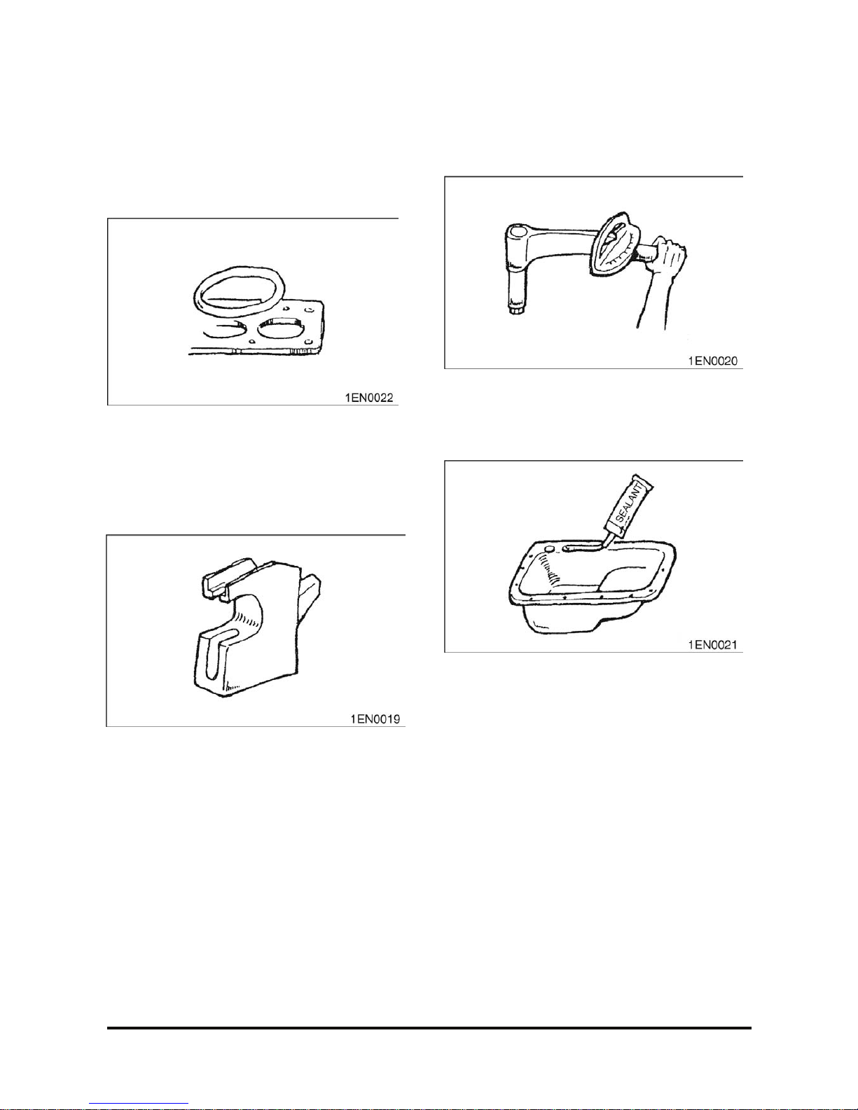
Removal and Disassembly
For prevention of wrong inst allation or reassembly
and for ease of operat ion, put m ating m ar k s to the
parts where no function is adv er s ely aff ec ted.
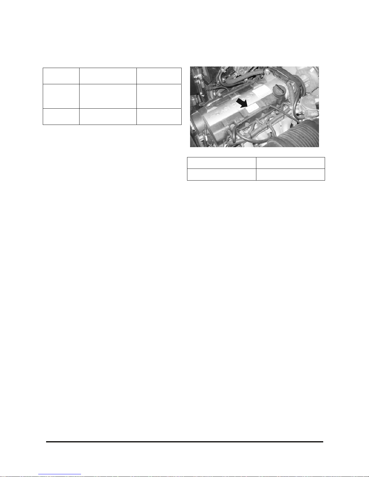
Special Tool
Be sure to use Special Tools when their use is
specified for t he oper ation.
Use of substitute tools will r es ult in malfunction of
the part or damage it.
Tightening Torque
Tighten the part properly to specified torque.
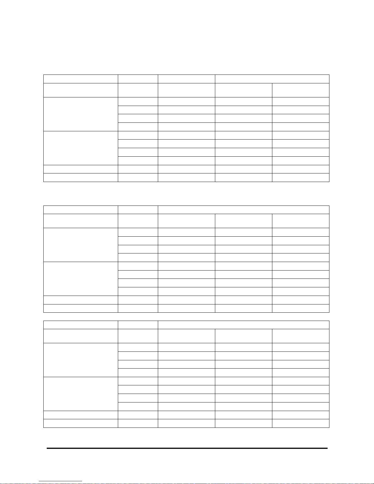
Sealant
Use specified brand of s ealant.
Use of sealant other than s pec ified sealant may
cause water or oil leaks.

G420F(FE) Servi ce Manual Chapter 1. General Info rmat ion 8
Replacement Part
When oil seal, O-ring, pac k ing and gas k et have
been removed, be sure t o replace t hem with new
parts.
However, rocker cover gasket may be reused if it is
not damaged.
Rubber Parts
Do not stain timing belt and V- belt with oil or water.
Therefore, do not clean the pulley and sprocket with
detergent.
Oil and Grease
Before reassembly , apply s pec ified oil to the rotating
and sliding parts.
Genuine Part
When the part is to be replaced, be s ur e to use
genuine part.
For selection of appropriate parts, refer to t he Parts
Catalog.
Electrical System
1. Be sure to disconnect the bat tery cable from the
negative(-) terminal of the battery.
2. Never pull on the wires when dis c onnec ting
connectors.
3. Locking connector s will c lic k when the connector
is secure.
4. Handle sensors and relays c ar efully. Be careful
not to drop them or hit them against other parts.

G420F(FE) Servi ce Manual Chapter 1. General Info rmat ion 9
Precautions for catalytic Converter
CAUTION
If a large amount of unburned gasoline flows
into the con verter, it may overheat and create a
fire hazard. To prevent this, observe the
following precau tions and explain them to your
customer.
1. Use only unleaded gasoline.
2. Do net run the engine while the tr uc k is at rest f or
a long time. Avoid running the engine at fast idle
for more than 5 minutes and at idle speed for
more than 10 minutes.
3. Avoid spark-jum p tests. Do spark-jumps only
when absolutely necessary . Perform this test as
rapidly as possible and, while t es ting, never race
the engine.
4. Do not measure engine compress ion for an
extended time. E ngine c om pr es s ion tests must be
made as rapidly as possible
5. Do not run the engine when the fuel tank is nearly
empty. This may cause the engine to m is fire and
create and extra load on the conv er ter.
6. Avoid coasting with the ignition turned off and
during prolonged braking
7. Do not dispose of a used catalyt ic c onv erter
together with parts contaminated with gasoline or
oil.

G420F(FE) Servi ce Manual Chapter 1. General Info rmat ion 10
Tighteni ng Torque
Tightening Torque Table of Standard Parts
Torque (kg·m)
Bolt nominal
diameter(mm)
Pitch(mm)
Head mark 4 Head mark 7
M5 0.8 0.3 ~ 0.4 0.5 ~ 0.6
M6 1.0 0.5 ~ 0.6 0.9 ~ 1.1
M8 1.25 1.2 ~ 1.5 2.0 ~ 2.5
M10 1.25 2.5 ~ 3.0 4.0 ~ 5.0
M12 1.25 3.5 ~ 4.5 6 ~ 8
M14 1.2 7.5 ~ 8.5 12 ~ 14
M16 1.5 11 ~ 13 18 ~ 21
M18 1.5 16 ~ 18 26 ~ 30
M20 1.5 22 ~ 25 36 ~ 42
M22 1.5 29 ~ 33 48 ~ 55
M24 1.5 37 ~ 42 61 ~ 70
M5 0.8 0.3 ~ 0.4 0.5 ~ 0.6
M6 1.0 0.5 ~ 0.6 0.9 ~ 1.1
M8 1.25 1.2 ~ 1.5 2.0 ~ 2.5
M10 1.25 2.5 ~ 3.0 4.0 ~ 5.0
NOTE: The torques shown in t he table are s tandard
vales under the following conditions.
1. Nuts and bolt are made of steel bar and
galvanized.
2. Galvanized plain st eel was her s ar e ins er ted.
3. All nuts, bolts, plain washer s ar e dr y .
NOTE: The torques shown in t he table are not
applicable,
1. When spring washers, toothed washers and the
like are inserted.
2. If plastic parts ar e fastened.
3. If oil is applied to thr eads and s urfac es .
NOTE: If you reduce the tor ques in the t able to the
percentage indicated below under the following
conditions, it will be the standard value.
1. If spring washers ar e us ed : 85%
2. If threads and bearing s ur faces are stained with
oil: 85%

G420F(FE) Servi ce Manual Chapter 1. General Info rmat ion 11
Recommended Lubric a nt s and Capaciti e s
Recommended Lubricants
Lubricant Specification Remarks
Engine Oil API Classification SJ or above SAE 10W30 or SAE 5W30
Coolant (Antifr eez e)
Automotive ant ifreeze
suitable for gasoline engines
having aluminum alloy parts
Concentration level 50%(nor m al)
Concentration level 40%(tropical)
Lubricant Capacities
Description G(C)18S-5, G(C)20SC-5 G(C)20/25/30E-5
Oil Pan 3.7 3.7
Oil Filter 0.3 0.3
Engine Oil (liters)
Total 4.0 4.0
Engine 3.0 3.0
Radiator & Hoses 5.5 5. 5
Coolant (liters)
Total 8.5 8.5
G420F(FE) Servi ce Manual Chapter 1. General Info rmat ion 12
Engine Model and Engine Serial
Number
Engine
Model
Fuel Type
Emission
Regulation
G420FE LP/Dual Fuel
EPA/CARB*
2007
Compliant
G420F
LP/Gasoline/Dual
Fuel
* EPA: Environmental Protection Agency
* CARB: California Air Resources Board
G420FE Engine
• Comply with EPA 2007 Emission Regulation
• Elec tronic Control by ECM
• Certified LP/Dual Fuel System available
– Closed loop LP Carburet ion syst em
– Closed loop MPI Gasoline system
• 3-way Catalytic Muffler is standard
G420F Engine
• Not c om ply with E PA 2007 Emission Regulation
• Elec tronic Control by ECM
• Standard LP/Gas/DF/Dual Fuel S y s tem available
– Open loop LP Carburetion system
– Closed loop MPI Gasoline system
• Muff ler is standard
Indication of Engine Model and Serial
Number
Engine Model Engine Serial Number
G420FE/G420F 30700001 to 39999999
Features and Benefi t s of G420F E/G420F Engine
• Al head with valve seat inserts
– Alum inum head and v alv e s eat system
• DO HC 16 valve sy stem
• Durable timing belt system
– Durable timing belt material and r ubber -
sealed cover
• Distributorless I gnition system (coil on plug)
• Electronic control system by ECM
(Engine control module)
– Drive-by-wire system
– Higher efficiency and lower f uel c ons um ption
– Min./Max. governor control
– Aut omatic engine protection f r om ov er heating
and/or low engine oil pressure
– Aut omatic transmission pr otection from
overheating
– Engine diagnostics by service-tool software
– Forklift ground speed limit ( optional)

G420F(FE) Servi ce Manual Chapter 1. General Info rmat ion 13
General Specification
G420FE Engine G420F Engine
GENERAL DESCRIPTION
ENGINE TYPE: Water - c ooled, Inline 4-Cycle, 4-Cylinders
COMBUSTION SYSTEM: Semi-Rent Roof
INTAKE MANIFOLD Cast Aluminum (wit h injec tor ports)
EXHAUST MANIFOLD Cast Iron, Dry
VALVE CONFIGURATION: DOHC, 4 Valves per Cylinder
VALVE LIFTER/LASH ADJUSTER Hydraulic Lash Adjuster
VALVE ROTATOR Intake/Ex haus t Rot ator
CAMSHAFT DRIVE Timing belt system ( 25.4 mm Toothed Belt)
DISPLACEMENT: 1,975 cc (120.5 cid)
BORE x STROKE 82mm (3.23 in) x 93.5 mm (3.68 in)
BLOCK STRUCTURE Grey Cast Iron
HEAD STRUCTURE Aluminum with seat ins er ts
COMPRESSION RATIO: 9.4:1
COMPRESSION PRESSURE: 1,450 kPa (210 psi)
Intake Valve: 2° BTDC(Open)/ 16° ABDC(Close)
VALVE TIMING:
Exhaust Valve: 6° BBDC(O pen)/ 2° ATDC(Close)
FIRING ORDER: 1-3-4-2
WEIGHT: 170 kg (Dry)
ENGINE ROTATION: Counter-Clockwise (CCW) when viewed from Flywheel End
FUEL TYPE: LPG, Gasoline, Dual F uel ( LPG or Gas oline)
CRANK VENTILATION Foul Air System with PCV
IGNTION SYSTEM
IGNITION TYPE: Distributorless (coil on plug)
IGNITION TIMING: Electronic cont r olled by E CM
POWER TRANSISTOR Ignition coil driver
IGNITION COIL: 12 V operation volt, 4 coils (c oil on plug)
SPARK PLUGS: Platimum Spark Plug (Air Gap: 0.8mm)
LUBRICATION SYSTEM
OIL PRESSURE: 167 kPa (24 psi) @ low Idle (90-100C oil temperature)
Upper Limit: 125°C ( 257°F)
Recommended: 99 - 110°C ( 210 - 230°F)
OIL TEMPERATURE:
Lower Limit:80°C ( 176° F)
OIL PAN Cast Aluminum
OIL PAN CAPACITY 3.7 L (EXCLUDES OIL FILTER)
OIL FILTER: 0.3 L
ENGINE OIL SPECIFICATION: API - SJ, SAE 10W30 or SAE 5W30
COOLING SYSTEM
WATER PUMP ROTATION: V-Belt Drive - Clockwise ( CW) when v iewed from engine front
THERMOSTAT: Opening Temperature: 82° C (180°F)
Fully Open Temperatur e: 95°C (203°F)
COOLING WATER CAPACITY: 3.0 L (block only)
G420F(FE) Servi ce Manual Chapter 1. General Info rmat ion 14
General Specification
G420FE Engine G420F Engine
LP FUEL SYS TEM
LP FUEL SYSTEM
Closed loop LP Carburetion
System
Open loop LP Carburetion Sy s tem
MIXER:
Diaphragm Type Air Valv e
Assembly inside, Downdr aft
(Model: CA-100)
Diaphragm Type Air Valv e
Assembly inside, Downdr aft
(Model: CA-100)
REGULATOR:
Two-Stage Negativ e P r es s ur e
Regulator (Model: N-2007)
Two-Stage Negativ e P r es s ur e
Regulator (Model: N-2001)
FUEL TRIM VALVE (FTV): Dual Dither System No FTV
FUEL FILTRATION: 40 Microns Maximum 40 Microns Maximum
GASOLINE FUEL SYSTEM
GASOLINE FUEL SYSTEM Closed loop MPI S y stem and In-Tank Fuel Pump System
FUEL PUMP MODULE Electric Fuel Pump (12V)
Fuel Filter & Strainer
Gasoline Pressure Regulator (3.5 bar)
FUEL INJECTOR ASS’Y Electric Fuel Injector (12V)
ENGINE ELECTRIC
ENGINE CONTROL
MODULE(ECM):
12 V operation volt, 48 pins of I/O
CRANK SENSOR Magnetic Inductive type
CAM SENSOR Hall sensor
TMAP: Intake Air Temp. & Manifold Absolute Press. Sensor
PEDAL ANGLE SENSOR: Two-Output Signals ( built in Accelerator Pedal)
Gasoline : One Oxygen sensor
OXYGEN SENSOR: Dual Oxygen Sensor S yst em
LPG: No Oxygen sensor
ECT-ECM: Engine Coolant Temperat ur e S ens or for ECM
ECT-GAUGE Engine Coolant Temp. S ens or for GAUGE on Instrument Panel
TPS: Throttle Pos ition Sens or ( built in Throttle Body)
THROTTLE BODY: Electronic Throttle B ody
LP FUEL LOCK-OFF: 12 V operation volt
ENGINE OIL PR. S/W: 28.4 kPa (4.1 psi)
STARTING MOTOR: 12 Volts, 1.7 kW
ALTERNATOR: 13.5 Volts, 90 Am p
EXHAUST SYSTEM
Muffler Catalytic Muffler Muffler (without cataly s t)
G420F(FE) Servi ce Manual Chapter 1. General Info rmat ion 15
Engine Power and Torque
G420FE Engine Power & Torque
FORKLIFT MODEL G(C)15/18S-5 G(C)20/25/30E-5
ENGINE MODEL G420FE-LP
G420FE-DF(LP)
& G420FE-LP
G420FE-DF(Gas)
RATED POWER Kw 33.6 39.5 39.5
hp 45 53 53
PS 46 54 54
rpm 2,400 2,550 2,550
MAX TORQUE N-m 147 157 157
lbf-ft 108 116 116
kgf-m 15,0 16.0 16.0
rpm 1600 1600 1600
GOVERNED SPEED rpm 2450 2600 2600
LOW IDLE rpm 750 750 750
G420F Engine Power & Torque
FORKLI FT M ODEL G(C)15/1 8 S -5
ENGINE MODEL
G420F-DF(LP)
& G420F-LP
G420F-DF(Gas) G420F-GAS
RATED POWER Kw 33.6 35.8 36.5
hp 45 48 49
PS 45.6 48.7 49.7
rpm 2,400 2,400 2,400
MAX TORQUE N-m 147 152 154
lbf-ft 108 112 114
kgf-m 15,0 15.5 15.7
rpm 1600 1600 1600
GOVERNED SPEED rpm 2450 2450 2450
LOW IDLE rpm 750 750 750
FORKLI FT M ODEL G(C)20/2 5 /3 0E-5
ENGINE MODEL
G420F-DF(LP)
& G420F-LP
G420F-DF(Gas) G420F-GAS
RATED POWER Kw 39.5 39.5 40.3
hp 53 53 54
PS 53.7 53.7 54.7
rpm 2,550 2,550 2,550
MAX TORQUE N-m 157 157 160
lbf-ft 116 116 118
kgf-m 16.0 16.0 16.3
rpm 1600 1600 1600
GOVERNED SPEED rpm 2600 2600 2600
LOW IDLE rpm 750 750 750
G420F(FE) Servi ce Manual Chapter 2. Recommended Maintenance 16
Chapter 2. RECOMMENDED MAINTENANCE
Suggested maintenance r equir em ents for an engine equipped with an MI-07 fuel system ar e contained in this
section. The oper ator should, however, develop a customized maintenance schedule using the requirements
listed in this section and any other requirements lis ted by the engine manufacturer .
General Mainte na nc e
Test Fuel System for Leaks
• O btain a leak check squirt bottle or pump spr ay
bottle.
• Fill the bott le with an approved leak check s olution.
• Spr ay a gener ous amount of the solution on the
fuel system fuel lines and connections, start ing at
the storage cont ainer .
• W ait approx imately 15-60 seconds, then perform a
visual inspection of the fuel system. Leaks will caus e
the solution to bubble.
• Listen for leaks
• Sm ell for LPG odor which may indicate a leak
• Repair any leak s before continuing.
• Crank the engine through several r ev olutions. This
will energize the fuel lock- off and allow fuel to flow to
the pressure regulat or /converter. Apply additional
leak check solution t o the regulator/ convert er fuel
connections and housing. Repeat leak inspection as
listed above.
• Repair any fuel leaks before cont inuing.
Inspect Engine for Fluid Leaks
• Start the engine and allow it to reach operat ing
temperatures.
• T ur n the engine off.
• I ns pec t t he entire engine for oil and/or coolant
leaks.
• Repair as nec es s ary before continuing.
Inspect Vacuum Lines and Fittings
• Vis ually ins pec t vacuum lines and fittings for
physical damage such as brittleness, cracks and
kinks. Repair/r eplac e as r equir ed.
• Solv ent or oil damage may cause vacuum lines to
become soft, resulting in a collapsed line while the
engine is running.
• I f abnorm ally s oft lines are detected, replac e as
necessary.
Inspect Electrical System
• Check for loose, dirty or damaged connectors and
wires on the harness including: fuel lock-off, TMAP
sensor, O2 sensors, electronic throttle, c ontrol
relays, fuel trim v alv es , cr ank pos ition sensor, and
cam position sensor.
• Repair and/or replace as necessary.
Inspect Foot Pedal Operation
• Ver ify foot pedal travel is smoot h without stic king.
G420F(FE) Servi ce Manual Chapter 2. Recommended Maintenance 17
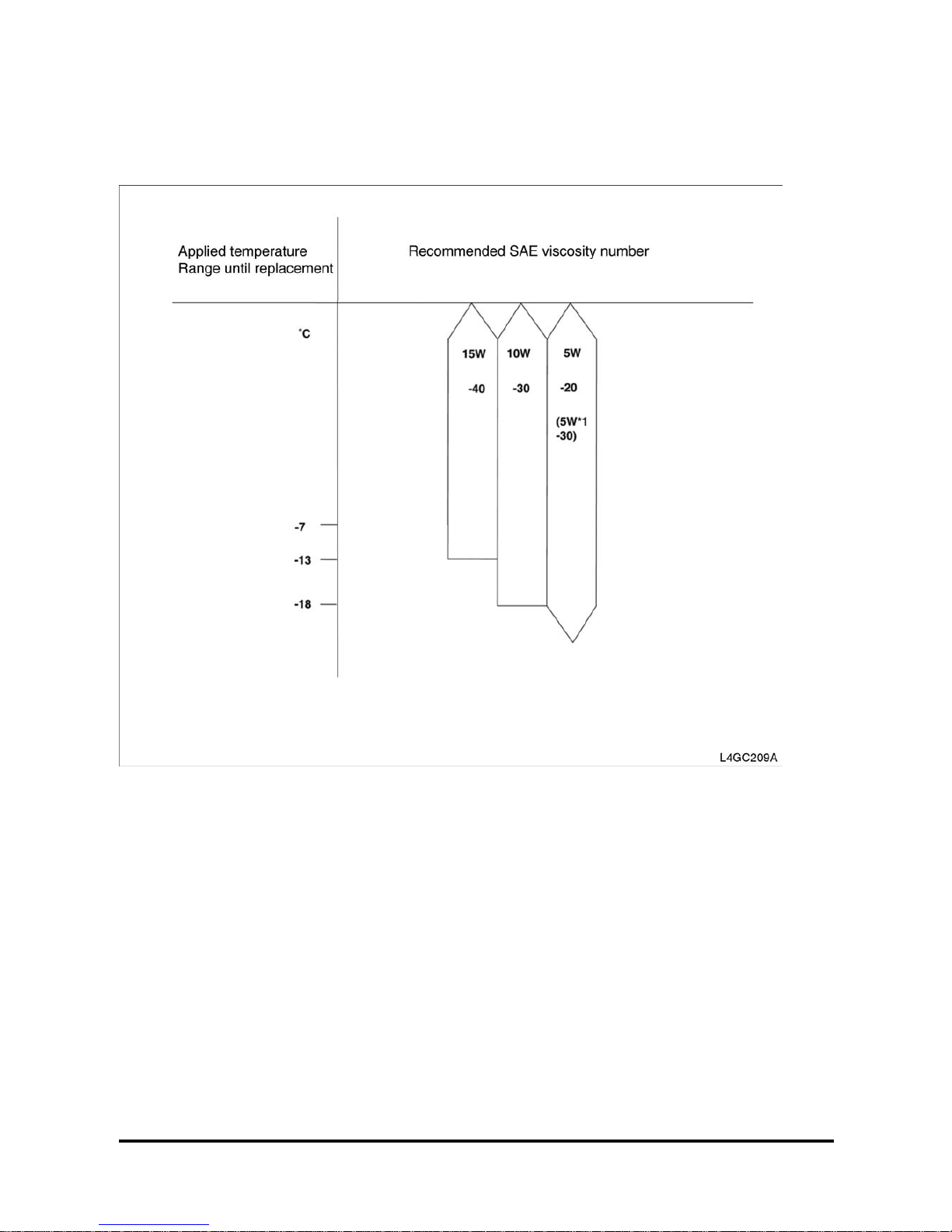
Engine Oil Classification
Recommended API clas s ification: Above SJ
Recommended SAE viscosity classification
The following lubricants s hould be s elec ted for all
engines to enhance excellent per formance and
maximum effect.
1. Observe the API classif ic ation guide.
2. Proper SAE classification number should be
selected within ambient temperature ranges. Do
not use the lubricant with SAE classification
number and API grade not identified on the
container.
*1. 10W-30 engine oil is recom m ended
If 10W- 30 is not applic able, proper engine oil will be possible ac c or ding to temperature ranges.

G420F(FE) Servi ce Manual Chapter 2. Recommended Maintenance 18
Checking Engine Oil Level
1. Check that the oil level is between “MIN” and
“Max” marks on the engine oil level gauge.
2. If the oil level is below “MIN” m ark, add oil until
the level is within the s pec ified ranges.
3. Check the engine for oil cont am ination and
viscosity and replac e if necessary.
Replacing Engine Oil and Filter
CAUTION
Prolonged and repeated contact with mineral oil
will result in the removal of natural fats from the
skin, leading to dryness, irri tation and dermat itis.
In addition, used engine oil contains potentially
harmful contaminants which may cause skin
cancer.
Exercise caution in order to minimize the leng th
and frequency of contact of your skin to used oil.
In order to preserve the environment, used oil
and used oil filter must be disposed of only at
designated di sposal sites.
1. Drain engine oil.
1) Remove the oil filler c ap.
2) Remove the oil drain plug, and dr ain the oil into
a container.
2. Replace oil filter.
1) Remove the oil filt er.
2) Check and clean the oil filter installation
surface.
3) Check the part number of the new oil filter is as
same as old one.
4) Apply clean engine oil to the gas k et of a new
oil filter.
5) Lightly screw t he oil filt er into place, and
tighten it until the gasket contacts the seat.
6) Tighten it an additional 3/4 turn.
3. Refill with engine oil filter.
1) Clean and install the oil drain plug wit h a new
gasket.
Torque
39.2~44.1N.m(4.0~4.5kgf.m,
28.9~32.5lb-ft)
2)Fill with fres h engine oil.
Capacity Drain
and refill
4.0L(4.23US qts , 3. 52Lm p qts)
Oil filter 0.3L(0.32US qts , 0. 26Lm p qts)
G420F(FE) Servi ce Manual Chapter 2. Recommended Maintenance 19
3) Install the oil filler c ap.
4. Start engine and check for oil leaks.
5. Recheck engine oil level.
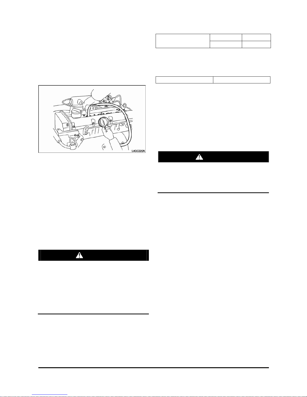
Checking Compressed Pressure
1. Prior to inspection, check that the engine oil,
starter motor and batt er y are normal.
2. Start the engine and run it unt il the engine coolant
temperature reac hes 80 ~ 95° C.
3. Stop the engine and disconnect the ignition coil
and air cleaner element.
4. Remove the spark plug.
5. After opening the t hr ott le v alv e c om pletely, crank
the engine to remove f or eign m aterial from the
cylinder.
CAUTION
At this time, necessarily screen the spark plug
hole with a rag. Because ho t cool ant, oil, fuel,
and other fore ign materia l, being penet r a te d in
the cylinder throug h cracks can come into the
spark hole during ch eckin g co mpressed
pressure.
When cranking the engine to t est compressed
pressure, necessarily open the throttle val ve before cranking.
6. Install the compr es s ion gauge to the spark plug
hole.
7. With the thrott le valve opened, c r ank the engine
to measure the compress ed pr es s ure.
Standard 15kg/㎠
Standard(250~400rpm)
Limit 14kg/㎠
8. Follow the procedur es ( no.6-7) to each cylinder
and check that compress ed pr es s ur e v alues of all
cylinders are within t he lim it.
Limit 1.0kg/㎠
9. If any of all cylinders is out of lim it, add a small
amount of engine oil to t he spark plug hole, and
re-proceed the procedur es ( no.6-7) to the c y linder .
At this time, if the compressed pressur e is increased,
it means that the piston, pis ton ring or cylinder
surface are worn or damaged, and if the
compressed pressur e is dec r eas ed, it means that
the valve is clogged, the valve contact is faulty, or
the pressure leaks through gasket.
CAUTION
If a large amo unt of incomple t e combust ion
gaso-line comes in to the cat alytic converter,
emergency such as a fire can occu r du e to
overheating. So this job should be done quickly
with the engine not operated.
G420F(FE) Servi ce Manual Chapter 2. Recommended Maintenance 20
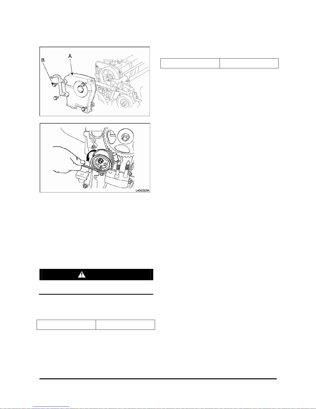
Adjusting Timing Belt Tension
Adjust the tension as t he following order .
1. Remove the fan driv e br ac k et.
2. Loosen the timing belt upper cover bolt (B) and
disconnect the upper c ov er (A).
3. As the illustrat ion, insert the hex wrench to the
adjuster groove and tur n it counterclockwise to
move the arm indi-cator in the middle of the base
groove.
CAUTION
If it is turned in reverse di rect io n, be su re th at
the tensioner may function abnormally.
4. Tighten the tensioner fixing bolt with the arm
indicator fixed.
Tightening torque 2. 3~2.9kgf·m
5. Rotate the cranks haft 2 turns c loc k wis e and make
sure the auto tensioner arm indic ator is placed in
the middle of the base gr oov e.
6. If the arm indicator is out of the m iddle, loosen the
bolt and repeat the prev ious pr oc edur e.
7. Install the tim ing belt upper cover (A) and tighten
the bolt(B).
Tightening torque 0.8~1.0k g·m
G420F(FE) Servi ce Manual Chapter 2. Recommended Maintenance 21
Cooling System Mai ntena nc e
Coolant Recommendation
The engine cooling system is provided with a
mixture of 50% ethylene glyc ol anti-freeze and 50%
water (For the vehicles of t r opic al area, the engine
cooling system is provided with a mixture of 40%
ethylene glycol anti-freeze and 60% water at the
time of manufactur e.)
Since the cylinder head and wat er pum p body ar e
made of aluminum alloy casting, be sure to use a 30
to 60% ethylene glycol ant ifreeze coolant to assure
corrosion protection and freezing prevent ion.
CAUTION
If the concentration of the antifreeze is below
30%, the anticorrosion property will be adversely
affected. In addition, if the concentration is
above 60%, both the antifreeze and engine
cooling properties will decrease, adversely
affecting the engine. For th ese reasons, be sure
to maintain the concentration level within the
specified range.
Coolant Water
Hard water, or water wit h high lev els of calc ium and
magnesium ions, encourages the formation of
insoluble chemical compoun ds by c om bining with
cooling system additives such as silicates and
phosphates.
The tendency of silicat es and phos phates to
precipitate out- of-solution increases with increasing
water hardness. Har d water, or water with high
levels of calcium and magnes ium ions enc our ages
the formation of insoluble c hem ic als , especially after
a number of heating and cooling cycles.
DOOSAN prefers the use of distilled water or
deionized water to reduce the potential and severity
of chemical insolubility .
Acceptable Water
Water Content Lim its (pps)
Chlorides (CI) 40 maximum
Sulfates (SO4) 50 maximum
Total Hardness 80mg/ℓ maximum
Total Solids 250 maximum
pH 6.0 ~ 8.0
ppm = parts per million
Antifreeze
DOOSAN recommends select ing automotive
antifreeze suit able for gasoline engines using
aluminum alloy parts. The antifreeze should meet
ASTM-D3306 standard.
Check Coolant Level
• T he items below are a general guideline for
system checks. Refer to the engine manufacturer’s
specific recomm endations for proper procedures .
• Engine m us t be off and cold.
WARNING—PROPER USE
Never remove the pressu re cap on a hot engin e.
• T he c oolant level should be equal to the “COLD”
mark on the coolant recover y tank.
• Add appr ov e c oolant to the specified level if the
system is low.
Inspect Coolant Hoses
• Vis ually ins pec t coolant hoses and clamps.
Remember to check the two coolant lines that
connect to the pressur e r egulator/convert er.
• Replace any hos e that shows signs of leakage,
swelling, cracking, abr as ion or deterioration.
G420F(FE) Servi ce Manual Chapter 2. Recommended Maintenance 22
Checking coolant leaks
1. After the coolant t em per ature drops below 38°C
loosen the radiator cap.
2. Check that the coolant level r eac hes filler neck.
3. Install the radiat or c ap tester to the radiator filler
neck and apply a pressure of 1.4kg/cm2 .
While maintaining it f or 2 minutes , check the
radiator, hose, and c onnec ting part for leak.
CAUTION
Because the coolant in th e radi ator is too hot,
never open the cap when it hot, or inj ury may
occur due to an outburst of hot water.
Dry out the inspection p art .
When removing the tester, take care not to spill
the coolant.
When removing/in st all in g the tester as well as
testing, take care not to deform the filler neck.
4. Replace parts if leak is detected.
Specific gravity test
1. Measure specif ic gravity of the coolant using a
hydrometer.
2. After measuring the coolant temperature,
calculate specific gr av ity using the following table.
Relation between Coolant concentration and Specific Gravity
Temperature and Sp ecifiv gravity of coolant (Temp.:℃)
10 20 30 40 50
Freezing
temp(℃)
Coolant Concentration
(Specific Volume)
1.054 1.050 1.046 1.042 1.036 -16 30%
1.063 1.058 1.054 1.049 1.044 -20 35%
1.071 1.067 1.062 1.057 1.052 -25 40%
1.079 1.074 1.069 1.064 1.058 -30 45%
1.087 1.082 1.076 1.070 1.064 -36 50%
1.095 1.090 1.084 1.077 1.070 -42 55%
1.103 1.098 1.092 1.084 1.076 -50 60%
G420F(FE) Servi ce Manual Chapter 2. Recommended Maintenance 23
Checking and Adjusting Drive Belt
1. Checking tension
1) Press the middle of the water pum p pulley and
alternator pulley wit h 10k gf.
2) Inspect the belt deflection by pressing it.
3) If the belt deflection is out of the standard,
adjust it as follows.
Standard
Item
New belt Used belt
Drive belt deflect ion ( L) 4.0~4.4mm 5.1~5.7mm
2. Using a tension gauge
1) Type
• BORROUGHS BT - 33 - 73F
• NIPPONDENSO BTG – 2
2) How to use
• Insert the belt between the gauge hook and
spindle and press the tens ion gauge handle.
• Leave the handle and read the gauge.
Standard
New belt Used beltTension(T)
65~75kg 40~50kg
CAUTION
The belt used over 5 minutes should be adjusted as used belt of st and ard
Check that the belt is installed correctly.
When the belt is loosened, sli p no ise is heard.
G420F(FE) Servi ce Manual Chapter 2. Recommended Maintenance 24
Adjusting
1. Loosen the alternator support bolt “A” nut and
adjusting lock bolt “B ” .
2. Adjust the belt tension by m ov ing the alternator
brace adjusting bolt t o “ T” dir ec tion.
Alternator adjusting lock bolt “B” 1.2~1.5kg·m
Alternator suppor t bolt “A” 2~2.5kg·m
3. Tighten the bolt “A ” and then tighten “B” to the
specified torque.
CAUTION
If the belt tension is too excessive, noise as well
as early wear of belt occurs and the water pu mp
bearing and altern at or bearing are damaged.
If the belt is too loose, due to early wear of belt
and insufficient power of alternator, battery and
water pump become inefficient and finally engine is overheated or damaged.
Checking Belt for Damage
Check the following item s and r eplac e the belt if
defective.
1. Check the belt surf ac e for dam age, wear and
crack.
2. Check the belt surf ac e for oil or grease
contamination.
3. Check the rubber part for wear or hardening.
4. Check the pulley surfac e for crack or damage.
Crank
pulley
G420F(FE) Servi ce Manual Chapter 2. Recommended Maintenance 25
Ignition Syst em Mai nt e nance
Inspect Battery System
• Clean bat tery outer surfaces wit h a mixt ur e of
baking soda and water.
• I ns pec t bat tery outer surfaces for damage and
replace as necessary.
• Remov e battery cables and clean, r epair and/or
replace as necessary.
Inspect Ignition System
• Remov e and ins pec t the spark plugs. Replace as
required.
• I nspect t he ignition coil for cracks and heat
deterioration. V is ually ins pec t the coil heat sink
fins. If any fins are br oken replace as required.
Inspection of Ignition Timing
1. Inspection c ondition
Coolant temperatur e : 80-90°C(At normal
Temperature)
Lamp and all accessories : OFF
Transmission : In neutral position
Parking brake : ON
2. Inspection
1) Connect the timing light.
2) Measure RPM.
RPM
Low Idle 750±15rpm
NOTE: If RPM is not normal, it is impos s ible to
measure the proper ignit ion timing, so measure it at
a normal RPM.
3) Inspect the standard ignit ion timing.
BTDC 5˚±5˚
4) If ignition timing is out of the standard, inspect
sensors concerned wit h ignition timing.
CAUTION
Because ignition timing is fixed by set data
value in ECU, it is impossible to control on
purpose.
Fist, check that sensors send output properly to
help determine ignition timing control.
NOTE: Affectiv e ECU input to lgnition timing control
• Coolant temperature sensor
• Oxygen sensor
• Battery voltage
• MA P sensor (Engine load)
• Crank s haft position sensor
• T hr ott le pos ition sensor
• Intake Air Temperature sensor
5) Check that actual ignit ion timing is changed
with engine RPM increased.
G420F(FE) Servi ce Manual Chapter 2. Recommended Maintenance 26
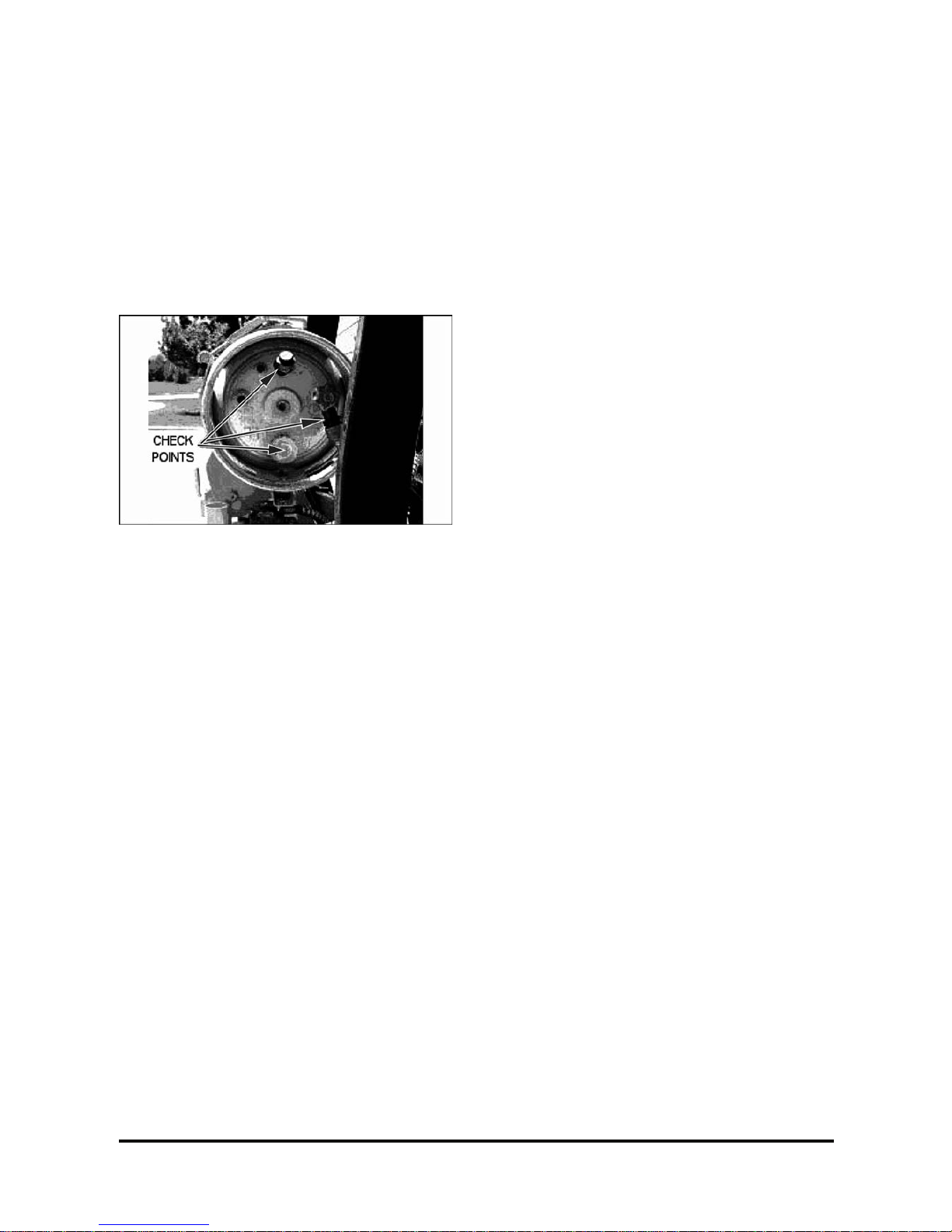
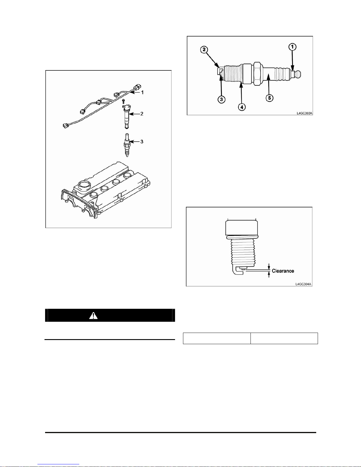
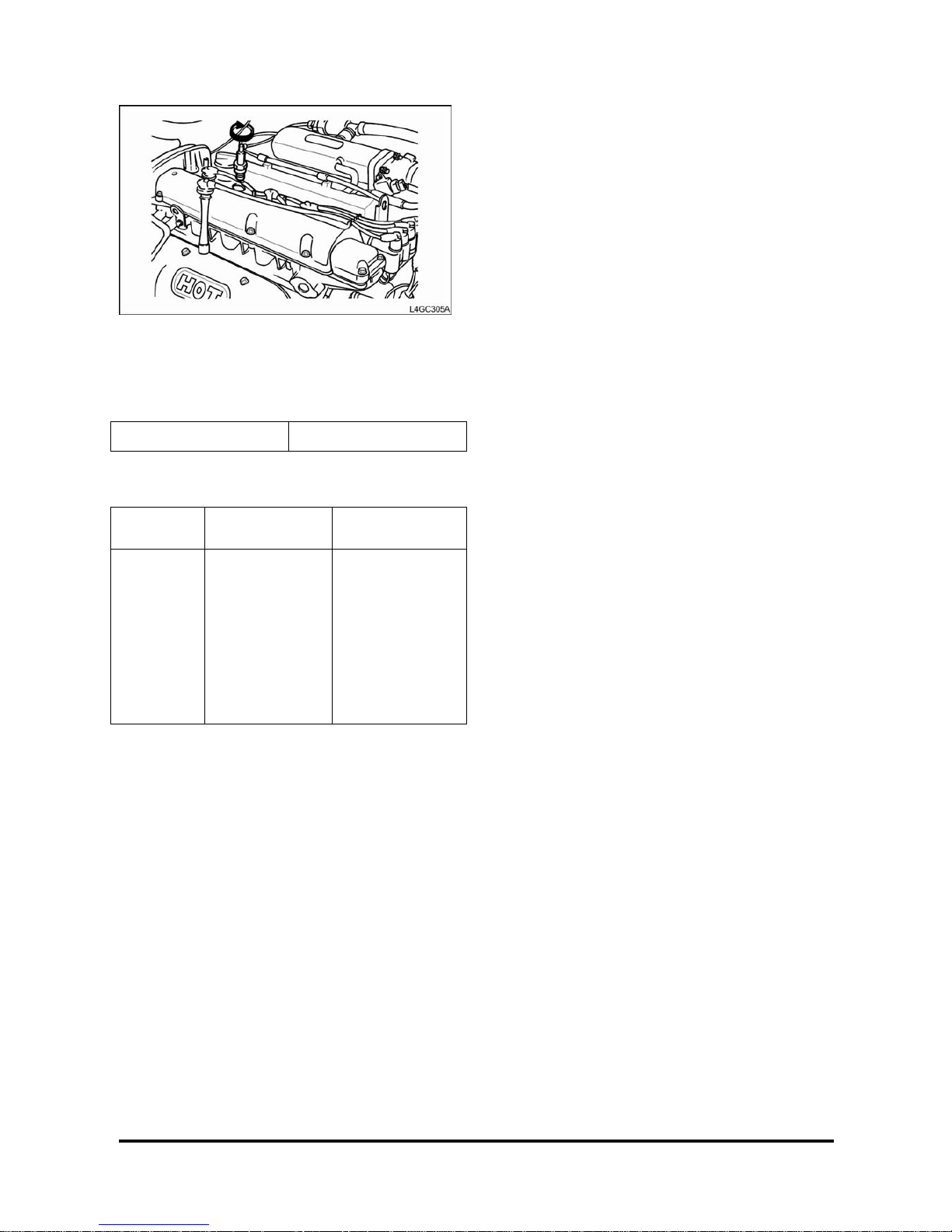
Inspection of Spark Plug
Inspection and clean
1) Ignition wire Ass’y
2) Ignition coil Ass’y
3) Spark plug
1. Disconnect t he ignition wire as s ’y from ignition
coil ass’y.
Remove the ignition coil ass ’y by pulling the ignition
coil hand.
2. Remove all spark plugs from the cy linder head
using a sparkplug wrench.
CAUTION
Take care not to come foreign materials into
spark-plug mounting hole.
3. Check the spark plug as below.
1) Insulator brok en
2) Terminal worn
3) Carbon deposit
4) Gasket damaged or broken
5) Porcelain insulator of spark plug clearance
4. Check the plug clearance using a plug clear anc e
gauge and if the value is not within the specified
values, adjust it by bending the gr ound c lear anc e.
When installing a new sparkplug, install it after
checking the uniform plug c lear anc e.
Spark plug clearance 0.7~0.8mm
G420F(FE) Servi ce Manual Chapter 2. Recommended Maintenance 27
5. Install the spark plug and tighten it to the specified
torque.
Take care not to over tight en it t o pr ev ent cy linder
head threads from dam age.
Tightening torque 2~3kg·m
SPARK PLUG ANALYSIS
State
Contact point is
black
Contact point is
white
Description
• Density of the
fuel mixture is
thick
• Density of the
fuel mixture is thin
• Lack of air
intake
• I gnition timing is
fast
• Spar k plug is
tight
• Lack of torque
G420F(FE) Servi ce Manual Chapter 2. Recommended Maintenance 28
Fuel System Maintena nc e
Replace LP Fuel Filter Element
Park the lift truck in an authorized refueling area with
the forks lowered, park ing br ak e applied and the
transmission in Neut r al.
1. Close the fuel shutof f valv e on the LP-fuel tank.
Run the engine until the fuel in the system runs
out and the engine stops.
2. Turn off the ignition switch.
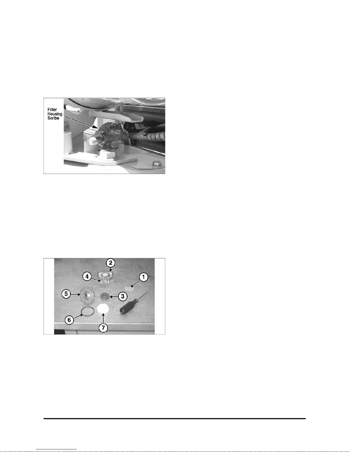
3. Scribe a line across the filt er hous ing c ov er s ,
which will be used for alignment pur pos es when
re-installing the f ilter cover.
FUEL FILTER DISASSEMBLY (Steps 4-7)
4. Remove the cover retaining screws (1).
5. Remove top cover (2), magnet (3), spring (4), and
filter element ( 7) from bottom cover (5).
6. Replace the filt er elem ent (7) .
7. Check bottom cover O- r ing s eal ( 6) f or damage.
Replace if necessary.
8. Re-assemble the filt er as s em bly aligning the
scribe lines on the top and bott om c ov er s.
9. Install the cover r etaining sc r ews , tightening the
screws in an opposite sequenc e ac r os s the cov er .
10. Open the fuel valve by slowly t ur ning the valve
counterclockwise.
11. Crank the engine sever al r ev olutions to open the
fuel lock-off. DO NOT START THE ENGINE.
Turn the ignition key s witch to the off position.
12. Check the filter hous ing, fuel lines and fittings for
leaks. Repair as necess ar y .
G420F(FE) Servi ce Manual Chapter 2. Recommended Maintenance 29
Testing Fuel Lock-off Operation
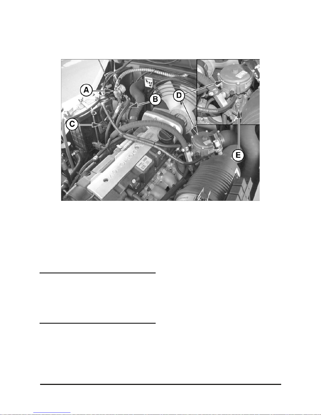
• Start engine.
• Locate t he electr ical connect or for the f uel lock (A).
• Disc onnec t the electrical connect or .
• T he engine s hould r un out of fuel and stop within a
short period of time.
NOTE
The length of time the engine runs on trapped fuel
vapor increases with any increase in distance
between the fuel lock-off and the pressure
regulator/converter.
• T ur n the ignit ion k ey switch off and re-connect the
fuel lock-off connect or .
Pressure Regulator/Converter
Inspection
• Vis ually ins pec t the pressure regulator /converter
(B) housing for coolant leaks.
• Ref er to Chapt er 5 if the pressure
regulator/conver ter requires replacem ent.
Fuel Trim Valve Inspec tion (FTV)
• Vis ually ins pec t the fuel trim valves (C) for
abrasions or cracking. Replace as necessary.
• T o ens ur e a valve is not leaking a blow-by test can
be performed.
1. With the engine off, dis c onnec t the electrical
connector to the FTVs.
2. Disconnect t he vacuum line from the FTVs to the
pressure regulator/converter at the c onverter’s
tee connection.
3. Lightly blow through the vacuum line connected to
the FTVs.
Air should not pass through t he FT V s when deenergized.
 Loading...