

Page 1
Vehicle System
SB4376E01
Aug.2012
Disassembly & Assembly
D110S-5 with OCDB
D130S-5 with OCDB
D160S-5 with OCDB
Page 2

Page 3
Important Safety Information
Most accidents involving pr oduct operation, maintenance and repair ar e caused by failure to observe basic
safety rules or precautions. An ac cident can often be avoided by recogniz ing potent ially hazardous sit uations
before an accident occurs. A person must be alert to potential hazards. This person should also have the
necessary training, skills and tools to perf orm these functions properly.
Read and understand all safety precau tions and warni ngs before operati ng or perfo rming lubrication ,
maintenance and repair on this product.
Basic safety pr ec autions are listed in the “Safety” section of the Ser v ic e or Technic al M anual. Additional safet y
precautions are list ed in the “Safety” section of t he owner/oper ation/maintenance publication.
Specific safet y warnings for all these public ations ar e provided in t he descript ion of oper ations wher e hazard s
exist. WARNING labels have also been put on the product to provide instructions and to identify specific
hazards. If these hazard warnings ar e not heeded, bodily injury or death could occur to you or other persons.
Warnings in this publication and on the product labels are ident ified by the following sym bol.
WARNING
Improper operation, lubrication, maintenance or repair of this product can be dangerous and could
result in in jury or death.
Do not operate or perfo rm any lubrication, maint enance or repair on this produ ct, until you have read
and understood the operation, lubrication, maintenance and repair information.
Operations that may cause product damage are identified by NOTICE labels on the product and in this
publication.
DOOSAN cannot anticipate ev ery possible circumstance that might involve a potential hazard. The warnings
in this publication and on the product are therefore not all inclusive. If a tool, procedure, work method or
operating technique not s pecifically recommended by DO OSAN is used, you must satisfy yourself t hat it is
safe for you and others. You should also ens ure that the product will not be damaged or made unsafe by the
operation, lubricat ion, maintenance or repair pr oc edur es y ou c hoos e.
The information, specifications , and illustrat ions in this publication are on t he basis of inf ormation available at
the time it was written. T he specifications, tor ques, pressures, measurement s, adjustments, illustrat ions, and
other items can c hange at any time. These changes can aff ect the service given to the produc t. Obtain the
complete and most current information before starting any job. DOOSAN dealers have the most current
information available.
Vehicle System Index 1
Page 4

Page 5

INDEX
Forks ........................................................ 5
Remove & Install Forks ..................................... 5
Carriage ................................................... 6
Remove & Install Carriage ................................. 6
Carriage Rollers ...................................... 7
Remove & Install Carriage Rollers ..................... 7
Disassemble & Assem ble Car r iage Roller s ........ 7
Disassemble & Assem ble Car r iage .................... 8
Mast ......................................................... 9
Remove Mast .................................................... 9
Install Mast ...................................................... 10
STD Mast ........................................................ 11
Disass embly ................................................ 11
Assembl y ........................................................ 1 4
FFT Mast......................................................... 18
Lift Cylinder ........................................... 20
Removal & Installation ..................................... 20
Disassembly .................................................... 22
Assembl y ........................................................ 2 4
Tilt Cylinder ........................................... 25
Removal & Installation ..................................... 25
Disassembly & Assembly ................................ 26
Brake Assembly .................................... 29
Removal & Installation ..................................... 29
Remote Control Valve .......................... 31
Replacing the parts ......................................... 31
Attachment Carriage ............................ 33
Lift Cylinder and Mast .......................... 33
Hydraulic Pump .................................... 35
Removal & Installation ..................................... 35
Start-up Inst ructions & Recommendations ....... 36
Rotation & Ports Indication ........................... 36
Start-up : ...................................................... 36
Removal of Air in Pump – Motor line ................ 36
Pump & Cartridge Breakdown Dr awing ............ 37
Disassembly .................................................... 38
Reasse mbly .................................................... 43
Seal Driver ...................................................... 48
Dimension of Protective Cone ......................... 48
Hydraulic Oil Filter ................................ 49
Removal & Installation ..................................... 49
Disassembly & Assembly ................................ 49
Universal Joint ......................................50
Removal & Installation .....................................50
Disassembly & Assembly .................................51
Steering Wheel & Gear .........................52
Steering Wheel ................................................52
Removed & Disassembly of Steering Gear.......52
Assembly of Steering Gear ..............................54
Steer Axle ..............................................58
Removal & Installation .....................................58
Steering Cylinder ..................................60
Removal & Installation .....................................60
Disassembly & Assembly .................................62
Steering Knuckle, Kingpin And Bearings
................................................................64
Removal & Installation .....................................64
Steer Tire And Rim ................................67
Removal & Installation .....................................67
Removal of Wheel Bear ing ..............................67
Installation of Wheel Bearing ............................68
Drive Tire And Rim ................................69
Removal & Installation .....................................69
Counterweight .......................................70
Removal of Air.......................................71
Pump – Motor line ............................................71
After changing main pump ...............................71
Air in Brake system ..........................................72
Removal of the High Pres sure in accumulator ..72
Emergency Lowering .......................................73
Removal and installation of Engine and
Transmi ssion ...................................................74
Vehicle System Index 3
Page 6

Page 7
Forks
Remove & Install Forks
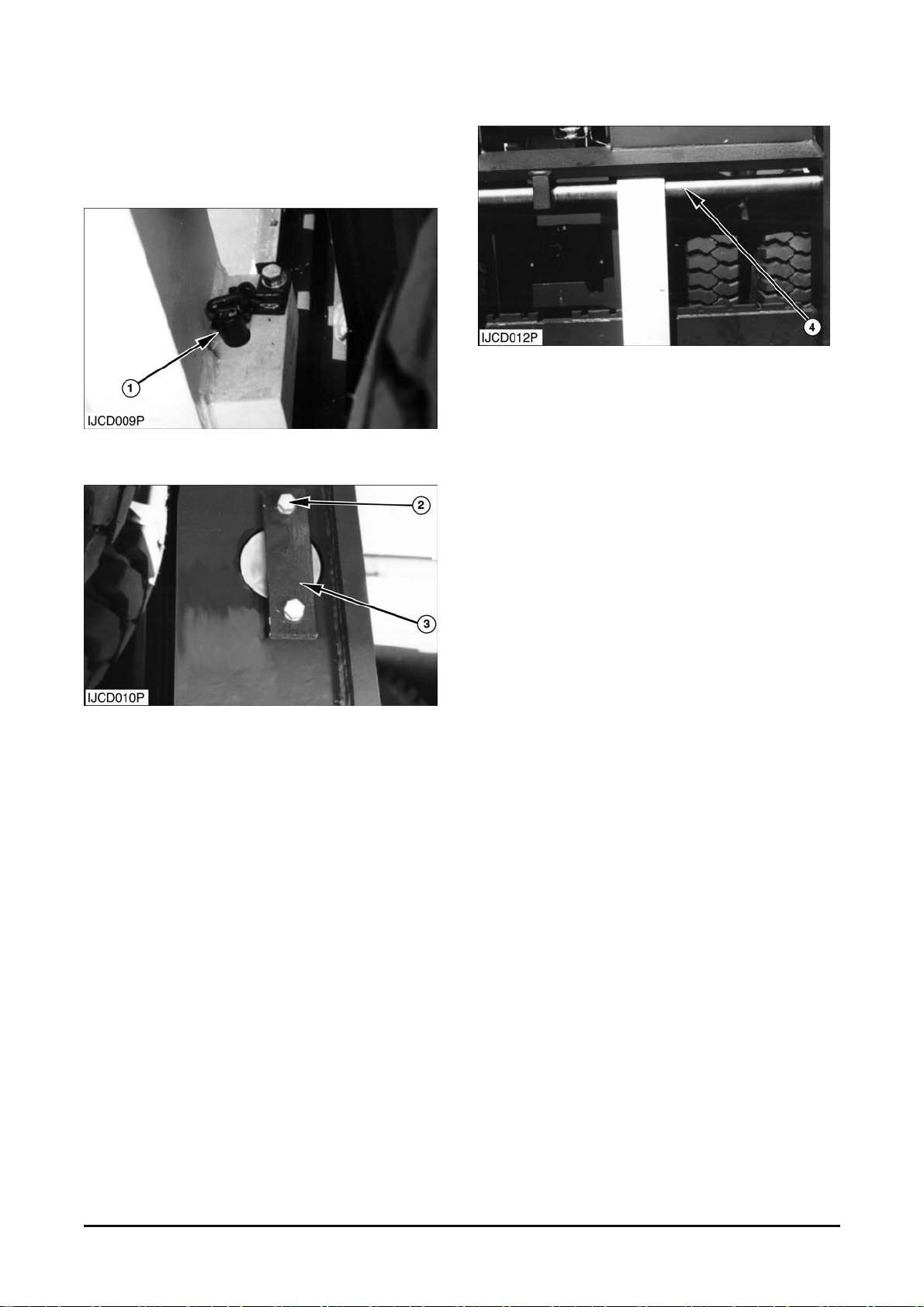
1. Pull out pin assembly ( 1) from the fork.
2. Rem ov e two bolts, washers (2) and plate ( 3) .
3. Support the fork with strap and hoist. Remove
shaft (4). Remov e str ap and hois t from the fork.
The weight of the fork is 217 to 465 kg (477 to
1025 lb).
4. Tilt the mast at full forward direction. Lower the
carriage until for k is s epar ated from the carriage.
Drive the truck at backwar d dir ec tion.
5. Repeat steps 1 through 4 f or the ot her fork.
6. Install the fork s in the rev erse order of removal.
Vehicle System Disassembly & Assembly 5
Page 8
Carriage
Remove & Install Carriage
Start By :
a. Remove forks.
1. Com pletely lower carriage and inner m as t.
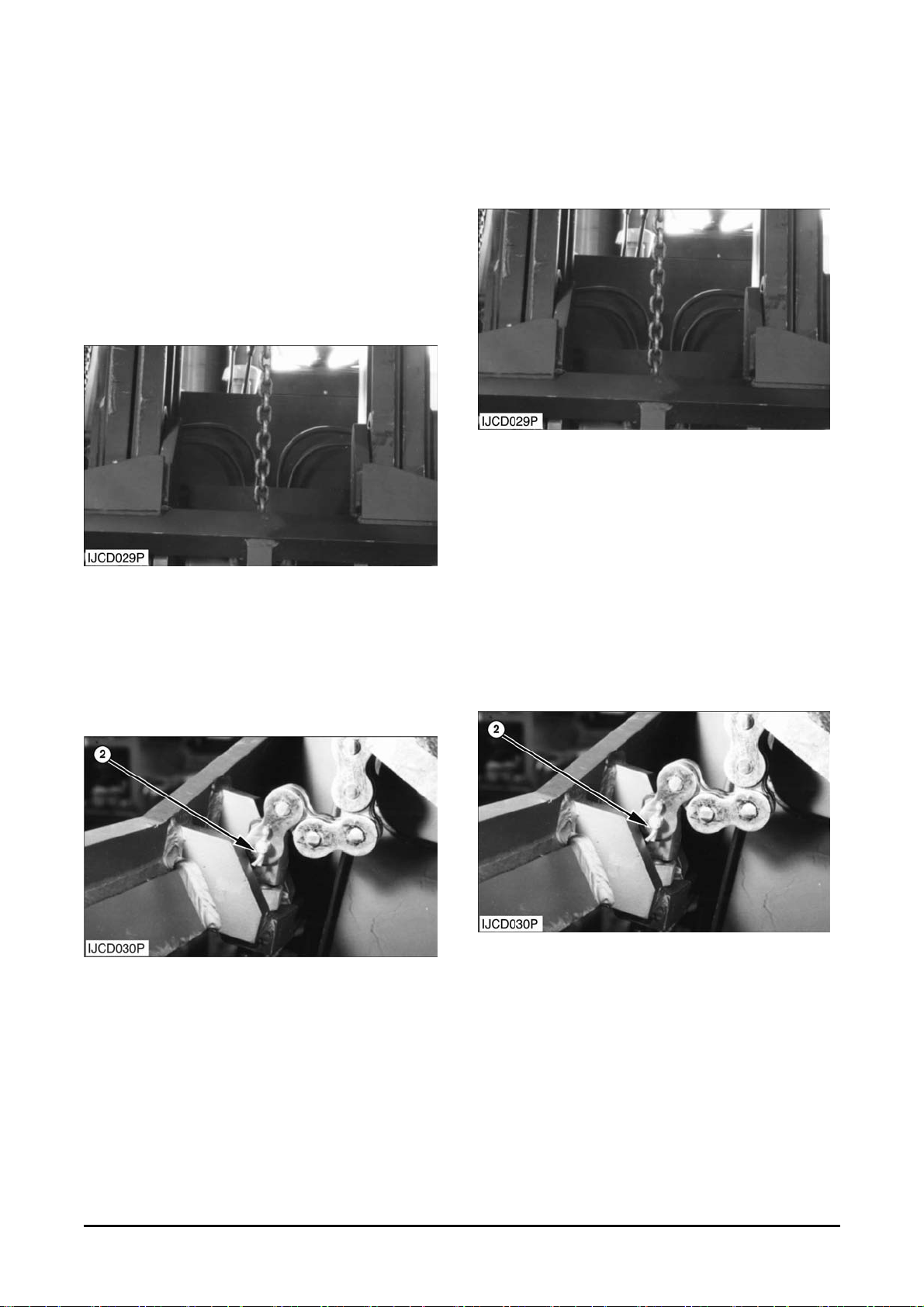
2. Attach a hoist t o the car r iage as shown.
3. Lift the car riage wit h the hoist unt il the chains and
hoses hang loosely.
4. Put identification marks on sideshift cylinder
hoses if equipped. Disconnec t two hoses.
5. Rem ov e the cotter pin and pin (2) f r om both of t he
lift chains.
6. Start the engine. Raise the mast until the inner
mast clears the car r iage.
7. Remove the carriage. The weight of the carriage
is 936 kg (2063 lb).
NOTE : The following steps are for installation of the
carriage. See the topic ent itled Carriage Adjustment
in the Testing and Adjusting Manual bef ore inst alling
the carriage on the m ast.
8. Attach a hoist t o the car r iage as shown.
9. Start the engine. Rais e the mast until t he carriage
will go under the inner mast .
10. Move the carriage in position under the mast.
11. Completely lower the mast over the carriage
making sure the roller s ar e pr oper ly aligned
inside the inner mast.
12. Connect two hoses. If necessary, rais e the
carriage slightly wit h the hoist.
13. Pull the chains into position on the carr iage.
Install pin (2) and t he cotter pin in both of the lift
chains.
14. Make an adjust m ent to the lift chains. See the
topic entitled Chain Adjus tments in the Testing
and Adjusting Manual.
End By :
a. Install forks.
Vehicle System Disassembly & Assembly 6
Page 9
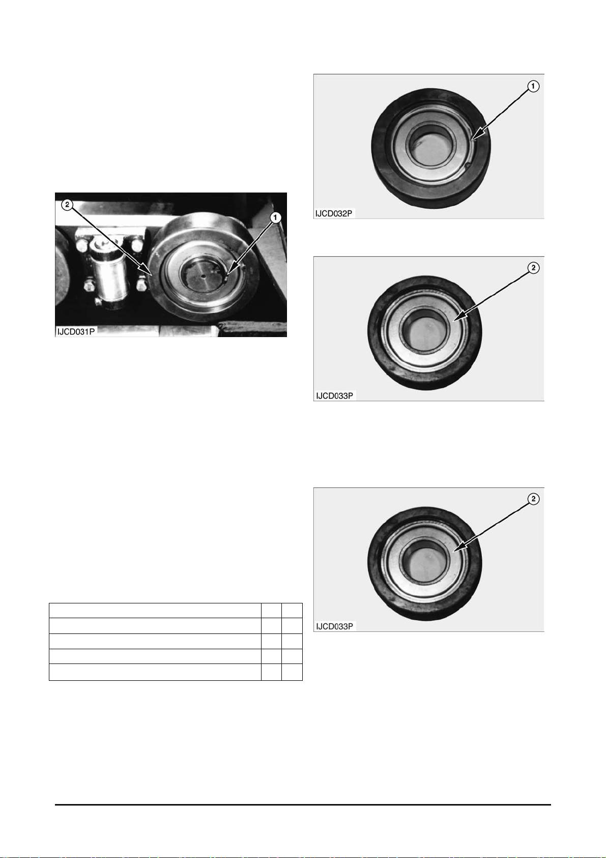
Carriage Rollers
Remove & Install Carriage Rollers
Start By :
a. Remove car r iage.
1. Remove the snap ring (1) that holds the roller in
place.
2. Remove load roller (2) from the carriage.
NOTE : The following steps are for installation of the
carriage rollers.
3. P ut the load roller in position on the carriage.
4. Install the snap ring that holds the roller in place.
End By :
a. Install carriage.
Disassemble & Assemble Carriage
Rollers
Tools Needed A B
Bearing Cup Puller Att achment
Puller Assembly
Ratchet Box Wrench
Bearing Installer
Start By :
a. Remove car r iage r oller s ( load) .
1
1
1
1
1. Rem ov e s nap ring (1) from the roller.
2. Remove bearing (2) from the roller using the tool
group (A).
NOTE : The following steps are for the as sembly of
the carriage rollers .
3. Put (pack) clean grease in the bearings for the
load roller.
4. Install bearing (2) in the roller using tool ( B ).
Vehicle System Disassembly & Assembly 7
Page 10
5. Install snap ring ( 1) in the roller.
End By :
a. Install carriage r oller s ( load)
Disassemble & Assemble Carriage
Start By :
a. Remove car r iage
Tools Needed A
Bearing Cup Puller Att achment 1
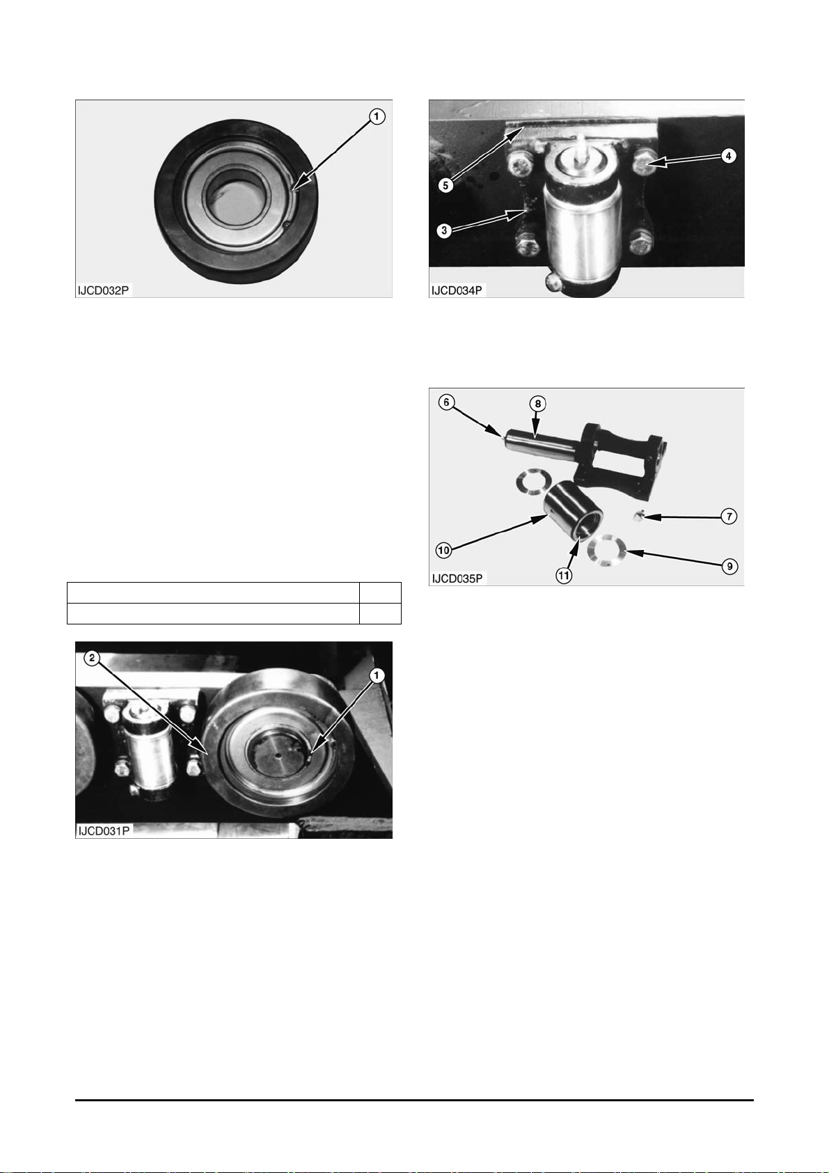
1. Remove snap ring (1) with tool (A).
2. Rem ov e roller (2) from the pin of the c arriage.
3. Remove bolts (4), washers, roller and bracket
assembly (3) and shims (5) from carriage
assembly.
4. Disassemble the roller and bracket assembly (3)
as follows:
a. Remove grease fitting (6).
b. Remove bolt (7) and washer that hold shaft (8)
in bracket.
NOTE : When assembly, apply Loctite No.242 to
bolt thread.
c. Tap the shaft ( 8) and r emove shaft from
bracket.
d. Remove spacers (9) and roller (10).
e. Remove bushings (11) from r oller ( 10) .
Replace the bushings with new ones if worn or
damaged.
NOTE : Assemble carriage in the reverse order of
disassembly.
End By :
a. Install carriage.
b. Make an adjustment to the carriage (see Carriage
Adjustment in Test ing and Adjusting).
Vehicle System Disassembly & Assembly 8
Page 11
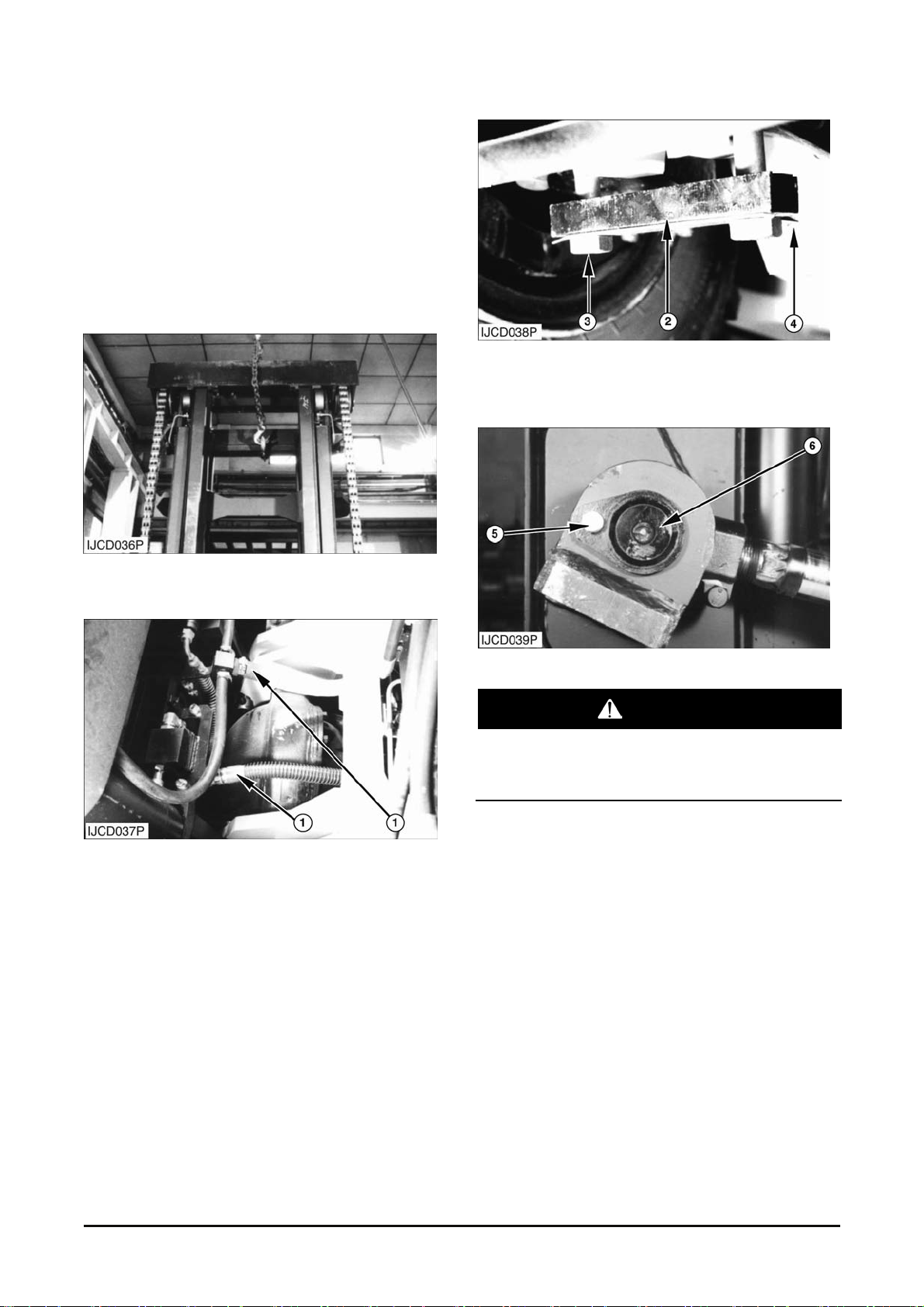
Mast
Remove Mast
Start By :
a. Remove carriage.
1. Fully lower mast.
2. Fasten a hoist to the mast as shown.
3. Tilt the mast forward. Disconnect hydraulic lines
(1).
4. B end bac k the tab on clip (4).
5. Remove bolt (3), clip (4) and block (2).
WARNING
Tilt cylinders can drop when pin (6) is removed.
To avoid component damage or personal injury,
support tilt cylinder while removing pin (6).
6. Remove retaining bolts (5). Remove pin (6).
7. Repeat Steps 4, 5 and 6 for the other side of t he
mast.
8. Start the engine. O perate the contr ol lever for the
tilt cylinders until the rods are fully retrac ted.
9. Remove the mast from the frame of the vehicle.
The weight of the mast is approximately 2600 to
4400 kg (5732 to 9700 lb).
Vehicle System Disassembly & Assembly 9
Page 12
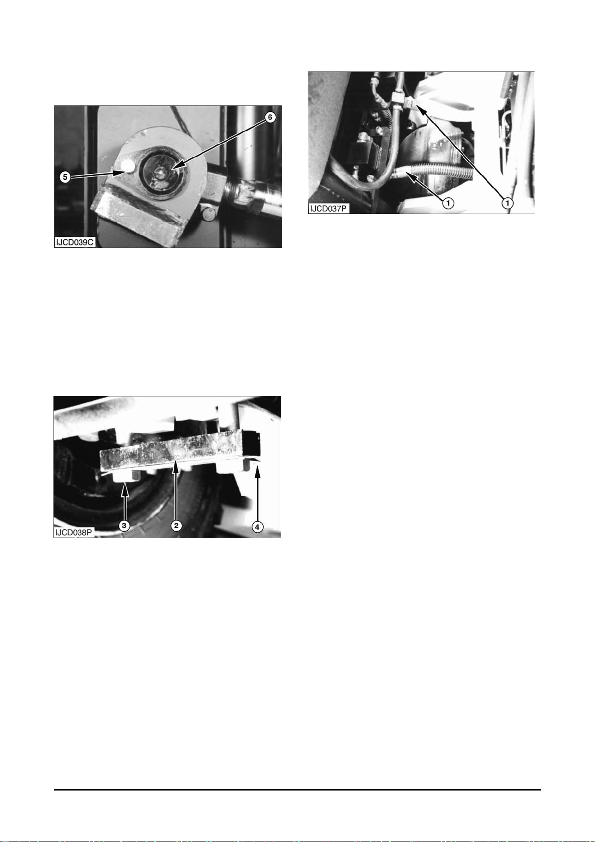
Install Mast
1. Install the mast on the frame of the vehicle. The
weight of the mast is appr oximately 2600 t o 4400
kg (5732 to 9700 lb).
2. Start the engine. O perate the contr ol lever for the
tilt cylinders until the holes in the cylinder rods are
aligned with the holes in the mas t.
3. Install two pins (6). Inst all bolts (5) and retainers
to hold both pins in place.
4. Inst all bolts (3), clip (4) and bloc k ( 2) on eac h s ide.
Torque bolts (3) to 800 ± 100 N•m (590 ± 74 lb•ft).
5. Bend back the tabs on clips (4) against the bolt
heads.
6. Connect hydr anlic lines ( 1) .
NOTE : If lift c ylinders wer e remov ed from the mas t,
adjust both lift chains to equal tension. Run the mast
to full lift. If mast does not kick to either side no
shims are required. If mast does kick to one side
disconnect cylinder from support assembly on that
side. Add shims, reassemble and repeat. Repeat
process until “kic king” is corr ected. Do not exceed 3
mm (.12 in) of shims.
End By :
a. Install brack et assembly carriage.
Vehicle System Disassembly & Assembly 10
Page 13
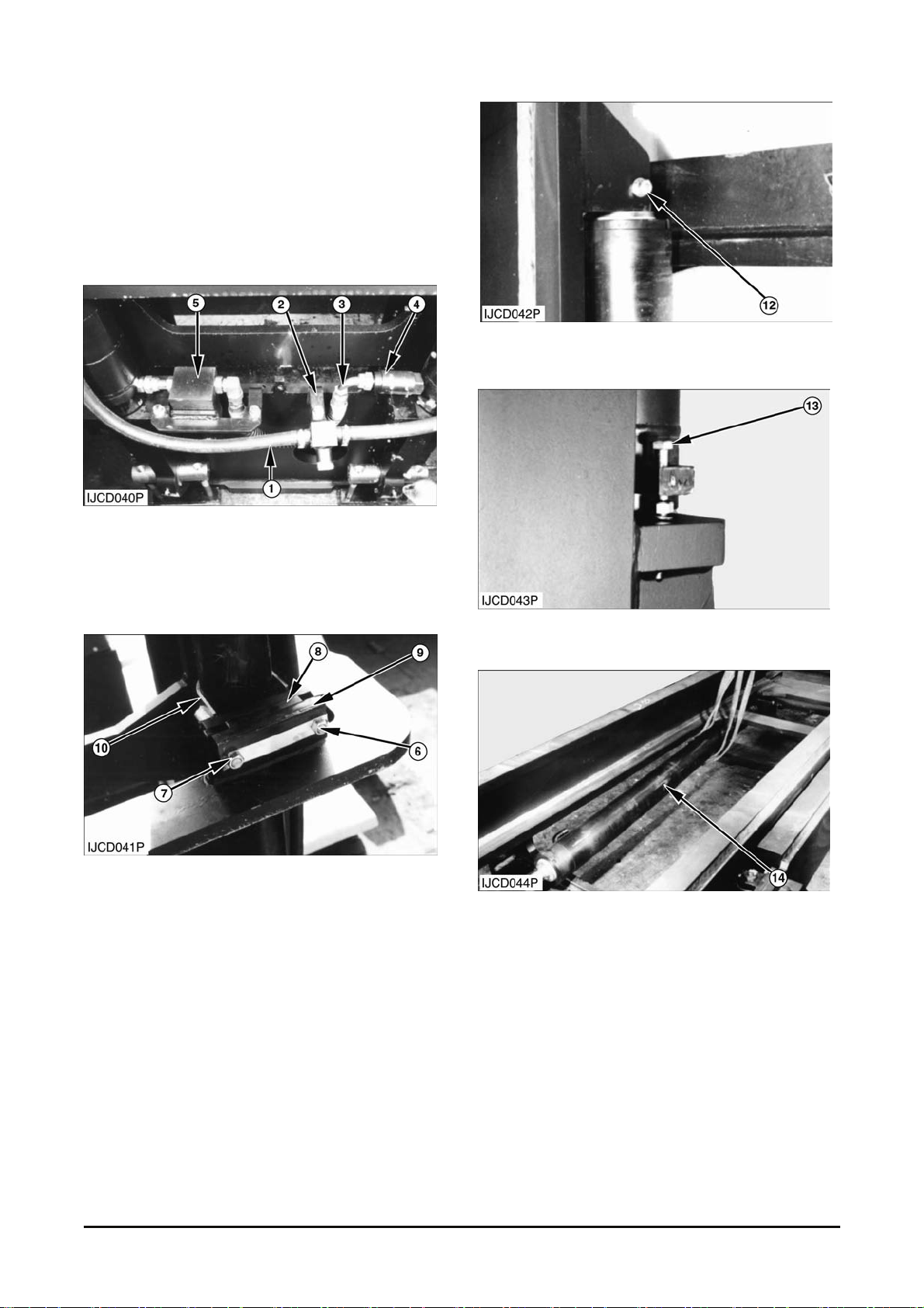
STD Mast
Disassembly
Start By :
a. Remove mast.
1. Rem ov e hos e (1) and bracket (2).
2. Remove hose (3), flow protector (4) and flow
regulating and bracket assembly (5) from outer
mast channel.
3. Bend back the plate (7) support ing nut (6) not to
be loosened. Remove nut (6), plate (7), spacers
(8), pad-rubber (9) and clamp assembly(10) if
they were installed.
4. Remove grease pipe if it was inst alled.
5. Rem ov e bolt (12) and washers.
6. Remove bolts (13) , washers and nuts.
7. A ttach hoist to lift cylinder (14).
8. Remove lift cy linder (14). The weight of the
cylinder is 171 to 400 kg (377 to 881 lb) . Mark for
identification and rem ove the shims at top of
cylinder (14).
NOTE : At inst allation, adjust both lift chains with t he
same tension. Run the mast to full lift. If mas t does
not kick to either side, no shimming is required. If
mast does kick to one side, disc onnect cylinder from
support assembly on that side. Add shims to
reassemble Repeat this process until “kicking” is
corrected.
Vehicle System Disassembly & Assembly 11
Page 14
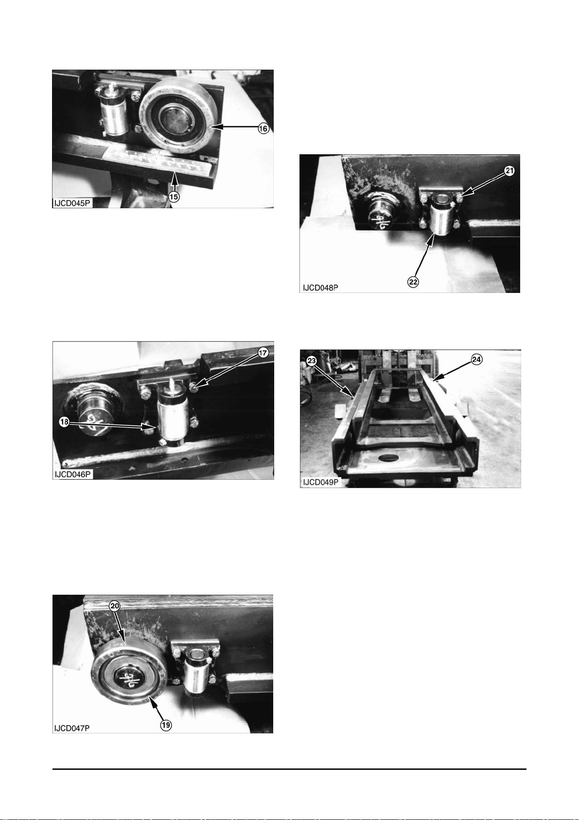
9. Remove pads (15) and shims from the outer mast
channel.
10. Remove the s nap- r ing from the outer mast pin.
Remove roller assemblies ( 16) from the outer
mast channel.
NOTE : Place identification marks on all roller
assemblies (16) t o as s ur e pr oper installation.
11. Remove bolts (17), washers, roller and bracket
assembly (18) and shims from the outer mast
channel.
NOTE : Mark and separate the shims and roller and
bracket assemblies (18) r emoved f rom each s ide for
identification at as s em bly .
12. Remove s nap-ring (19) from the inner m ast pin.
Remove roller assemblies (20) from the inner
mast channel.
NOTE : Place identification marks on all roller
assemblies (20) t o as s ur e pr oper installation.
13. Remove bolts (21), washers, roller and bracket
assembly (22) and shims from the inner mast
channel.
14. Remove c hains from the outer mast.
15. Repeat st eps 10 through 13 for the other side.
16. Fas ten a hoist to outer mast (23). Use a lift truck
to separate inner m as t (24) from outer mast (23).
The weight of outer mast (23) is about 1230kg
(2771lb) and The weight of inner mast (24) is
about 910kg (2006lb).
Vehicle System Disassembly & Assembly 12
Page 15
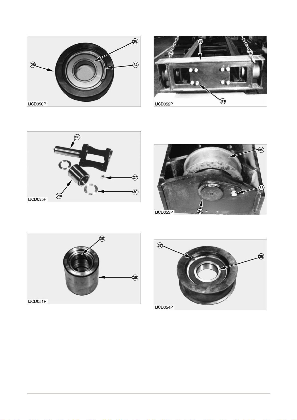
17. Remove s nap- r ing ( 24) , bearing (25) from roller
(26) if needed.
18. Remove bolt ( 27) , washer and grease fitting. T ap
the shaft and remove s haft ( 28) , spac er s (30),
and roller (29) from the brac k et if needed.
19. Check the c ondition of bushing (30) in the roller
(29). Replace the bushing (30) with new one if
worn or damaged.
20. Support crosshead assembly ( 32) with a hois t
and remove eight bolts, washers (31) and
crosshead assembly (32) from the inner mast
channel.
21. Remove r etaining bolts, washers ( 33) and pins
(34) and then remove c hain s heav es ( 35).
22. Remove snap-r ing ( 37) and bear ing (38) from
the wheel if needed.
Vehicle System Disassembly & Assembly 13
Page 16
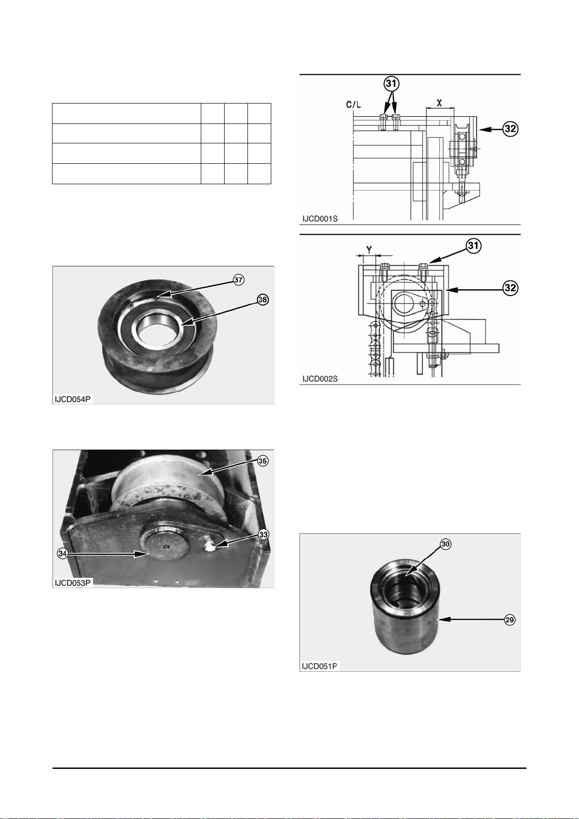
Assembly
Tools Needed A B C
Vernier Calipers 1
Inside Vernier Calipers 1
Mast Gauge 1
1. Make sure all parts are clean and free of dirt and
foreign material.
2. Check all parts for damage. If damaged, use new
parts for replacement.
3. Install bearing (38) and snap ring (37) into the
wheel if they were rem ov ed.
4. Inst all chain sheav es (35), pins (34), washer s and
retaining bolts (33) that hold pins (34) to the
crosshead assembly.
5. Put crosshead assembly (32) in position and
install washers and bolts (31). Adjust crosshead
assembly (32) of which distance difference (X)
between left hand and right hand should be within
1.5mm(.06 in) from side of the inner beam.
Tighten bolts.
6. When crosshead assembly (32) is assembled,
distance difference (Y) between left hand and
right hand should be wit hin 1.5 mm (.06 in) f rom
front of the inner beam .
7. Install new bushes (30) into the roller.
Vehicle System Disassembly & Assembly 14
Page 17
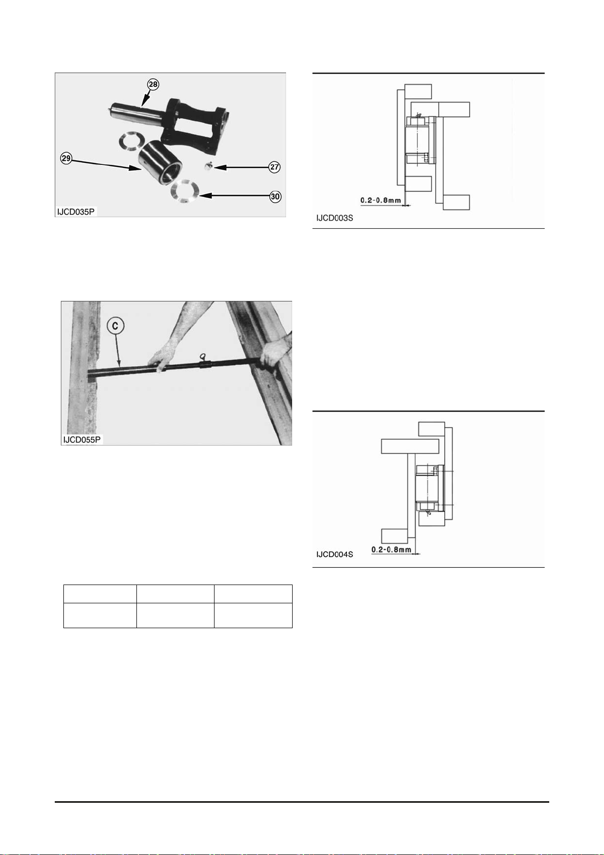
8. Install the shaft, spacers and roller (29) to the
bracket.
Install bolt (27) and washer using Loctit e No.242.
Install grease fitting (28) to the shaft. Be careful
for assembling direc tion.
Typical Example
9. To shim the inner m ast (lower) side roller, move
gauge (C) up and down inside outer mas t channel
(8) to find the narrowest point across the outer
mast channels in track wher e the side roller t ravel.
Measure the channel lap which is the distance
between the outer rail upper face and inner rail
lower face. Record this measurement. The
channel lap is to be shown in the below t able.
MFH 3.0~4.5 M 5.0~6.0 M
CHANNEL
LAP
1115 mm 1315 mm
10. Inst all the inner mast channel side roller and
bracket assemblies (22) without shims on the
inner mast.
11. Measure t he dis tance between inner mast side
rollers with tool ( A ) . Add s him s between one of
side rollers to be 0.2~0.8 mm (.008~.031 in)
clearance.
12. Divide t he s him s into two groups to have the
same thickness and ins tall them on each side of
the inner channel behind side roll er and bracket
assemblies (22).
13. To shim outer mast (upper) side roller(18) ,
measure outside of the inner m as t channel ( 24)
to find the widest point ac r os s t he inner m ast
channels in the track where side roller (18) travel
using tool (A). Rec ord this measurement.
14. Ins tall the outer mast channel side roller and
bracket assemblies (18) without shims on the
outer mast.
15. Measure t he dis tance between outer mast side
rollers (18) with tool (B). Add shims between one
of side rollers t o be 0.2~ 0.8 mm (.008~.031 in)
clearance.
Vehicle System Disassembly & Assembly 15
Page 18
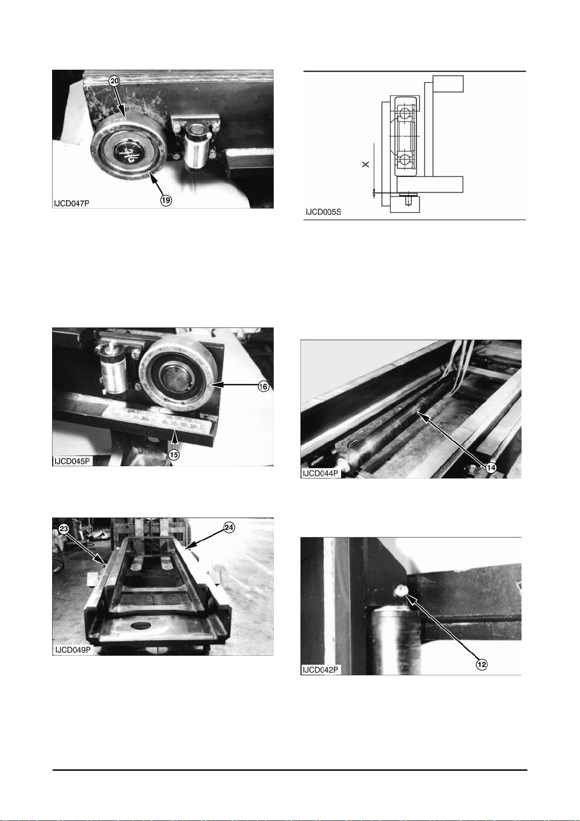
NOTE : Assemble after spray to anti-seizing
lubricant, Molybdenum disulfide type between
bearing and roller.
16. Ass em ble the bearings and snap rings into the
rollers if they were removed. Install roller
assemblies (20) on t he inner m as t pin. Install
snap rings (19).
17. Ins tall roller assemblies (16) on the outer mast
pin. Install t he snap rings.
18. Use a hoist and nylon strap to install inner m ast
(24) into outer m ast c hannel ( 23) .
The weight of outer mast ( 23) is about 1230k g
(2771lb) and The weight of inner m as t (24) is
about 910kg (2006lb).
19. Place the shims between wear pads ( 15) and the
inner mast. Clearance (X) between outer roller
(16) and inner mast flange is to be 0.0 to 1.0 mm
(.0 to .04 in).
20. Slide the mas t completely together.
21. Inst all the chains on each side of the outer mast.
22. Fas ten a hoist and nylon str ap to lift cylinder ( 14)
and put lift cylinder (14) and shims in position.
Install bolts ( 13), washers and nut.
23. Ins tall bolts (12) and washers on the inner m ast.
Apply the Loctit e No.242 t o thread of bolts (12).
Vehicle System Disassembly & Assembly 16
Page 19

24. Ins tall clamp assembly (10), pad- r ubber (9),
spacers (8), plate (7) and nut (6). Bend plate (7)
supporting nut (6) not to be loosened.
NOTICE
Make lift cylinders vertical by adjusting pad-rubber
(9) and U-clamp assem bly ( 10).
25. Ins tall grease pipe if it was removed.
26. Install t he flow regulating and bracket assembly
(5), flow protector (4) and hose (3).
27. Ins tall bracket (2) and hose (1).
End By :
a. Install mast.
Vehicle System Disassembly & Assembly 17
Page 20
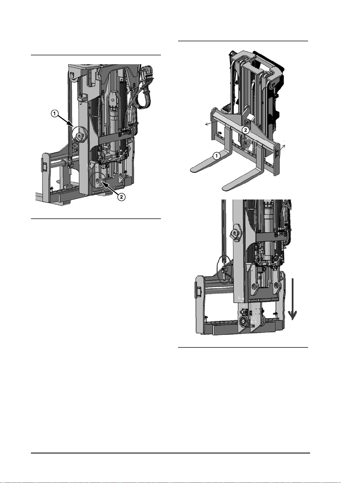
FFT Mast
NOTE: Since many things f or FFT are same for STD,
please also refer to the instruction for STD.
1. Remove the mast chassis
a) Remove tilt pin from the (1) & tilt cy linder
b) Remove hinge pin (2)
c) Remove mast from chassis
Tilt
Shaft
Cover
Chain anchor
2. Rem ov e fork & carriage
( How to same the STD mast)
a) Remove fork(1) - Remove cover & shaf t
b) Remove carriage(2) - Rem ov e c ar riage chain
anchor
Vehicle System Disassembly & Assembly
18
Page 21
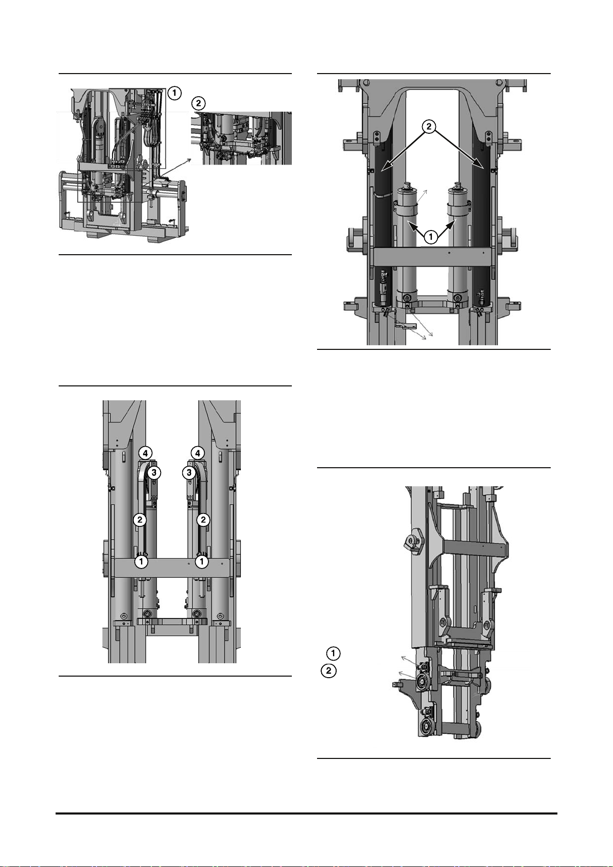
3. Rem ov e hy draulic line.
a) Remove attachment line(1)
- Remove bolt & fitting
- Close the port with plug
b) Remove lift line( 2)
- Remove clamp & fitting
- Close the port with plug
4. Rem ov e c hain & c rosshead.
a) Remove chain anchor bolt ( 1) - Rem ov e pin
b) Remove chain(2)
c) Remove chain sheave - Remove pin(3)
d) Remove crosshead( 4) - Remove bolt
clamp
Bolt(pin)
5. Remove cylinder
a) Remove primary cylinder
- Remove clamp(1)
- Remove cylinder f itt ing bolt
b) Remove secondary c y linder ( 2)
- Remove cylinder f itt ing bolt
Side Roller As
Mast Roller As
Vehicle System Index 19
Page 22
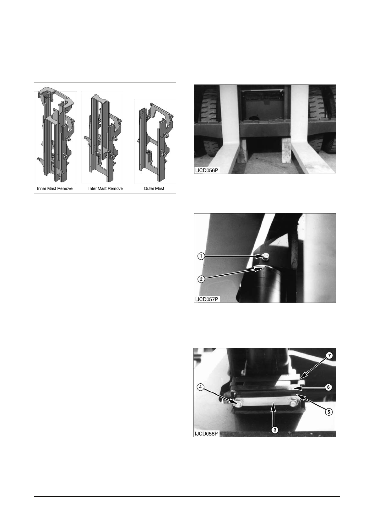
6. Rem ov e bearing & mast as
a) Remove side roller bearing ( 1)
b) Remove mast roller bearing ( 2)
End by:
a. Install car r iage, raise the inner mast and ins er t t he
carriage from bott om of inner mast.
Lift Cylinder
Removal & Installation
1. Start the engine and l ift the inner mast. Put blocks
under the inner mast as shown and lower the
weight on the blocks. Tilt the mast forward fulling.
2. Fasten a hoist to the lif t cy linder .
3. Remove bolt (1) and was hers that hold rod (2) to
the inner mast.
4. Bend back plate (3) s upporting nut (4) not to be
loosened. Remove nut (4) , plate (3), s pacers (5),
rubber pad (6) and clamp assembly (7) if they
were installed.
Vehicle System Disassembly & Assembly
20
Page 23
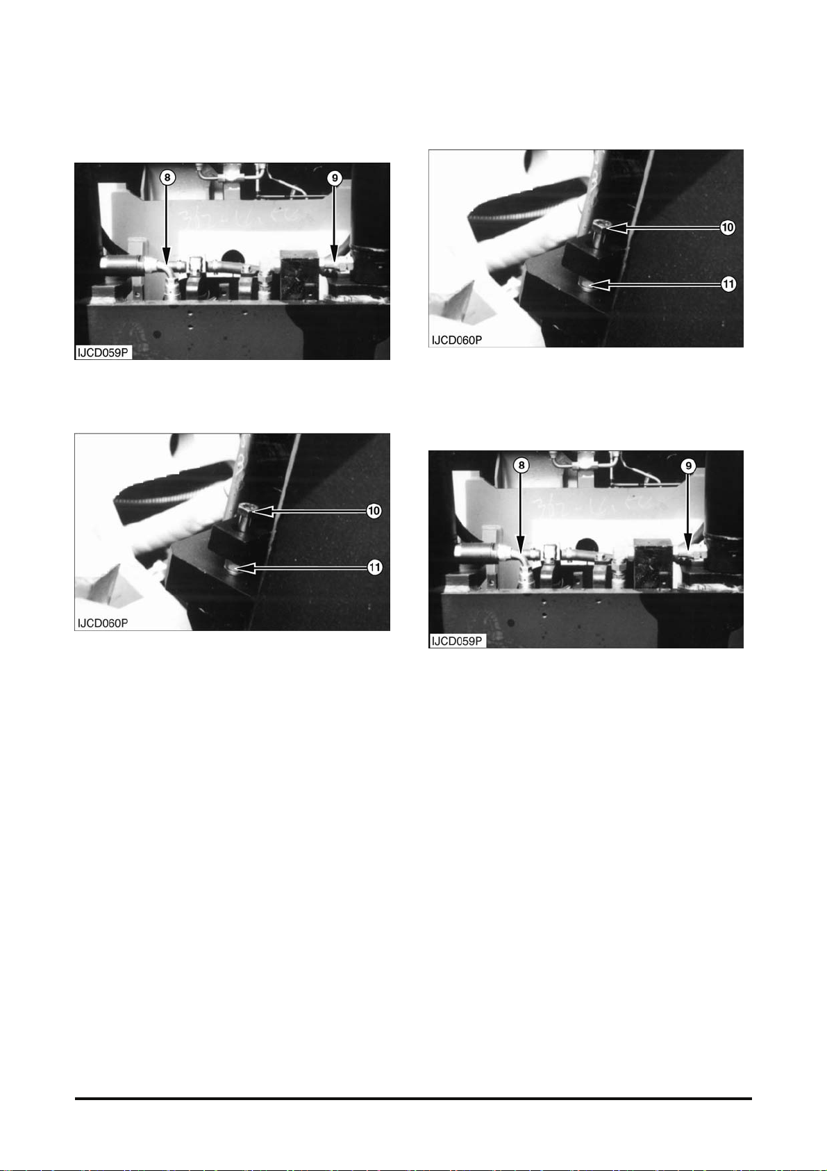
5. Move the lift control lev er to the "DOWN" position
and push rod (2) into t he cylinder to get enough
clearance for rem ov al.
6. Disconnect hydr aulic lines (8) and (9) from the lift
cylinder.
7. Remove bolt (10) , washers and nut (11) t hat hold
the bottom of the cylinder to the mast.
8. Remove the lift cylinder from the machine. The
weight of the cylinder is 171 to 319 kg (377 to 703
lb).
NOTE : The following steps are for the installation of
the lift cylinder.
9. Fasten a hoist to the lift cylinder and put it in
position on the mast. Install t he washers, nut (11)
and bolt (10). Tighten nut (11) to a torque of
55~80 N∙m (40~60 lb∙ft).
10. Connect hy dr aulic lines ( 8) and ( 9) to the lift
cylinder.
Vehicle System Index 21
Page 24
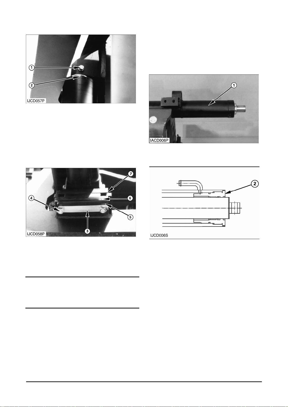
11. Make s ur e the bolt holes in the end of rod (2) are
in alignment with the bolt holes in the inner mast
plate. Start t he engine. Move rod (2) out of the
cylinder until it is in c or r ec t alignment with the
inner mast plate.
12. Ins tall bolt (1) and washer that hold r od ( 2) to the
inner mast. Tight en bolt (1) to a torque of 55~80
N∙m (40~60 lb∙ft) with Loctite No.242.
13. Inst all c lam p as s em bly ( 7), r ubber pad (6),
spacers (5), plates (4) and nut (4). Bend plates
(4) that nut (4) does not loos e.
Disassembly
Start By :
a. Remove lift cy linder .
Typical Example
1. P ut lift cylinder (1) in position as shown.
2. Remove head assembly ( 2) with tool.
NOTICE
Make lift cylinder ver tical by adjusting r ubber pad (6)
and U-clamp assembly ( 7) .
14. Lift the mast and remove the blocks from under
the inner mast. Lower the mast and stop the
engine.
Vehicle System Disassembly & Assembly 22
Page 25
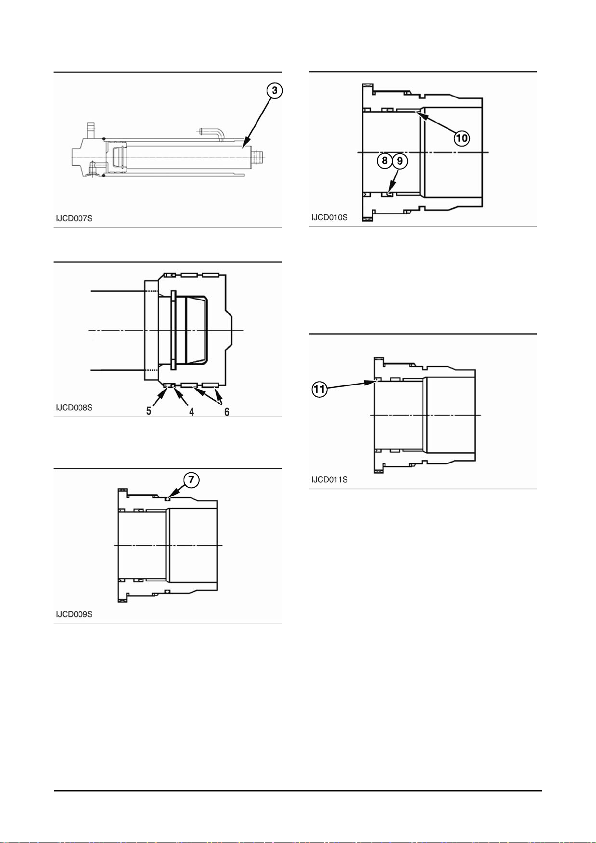
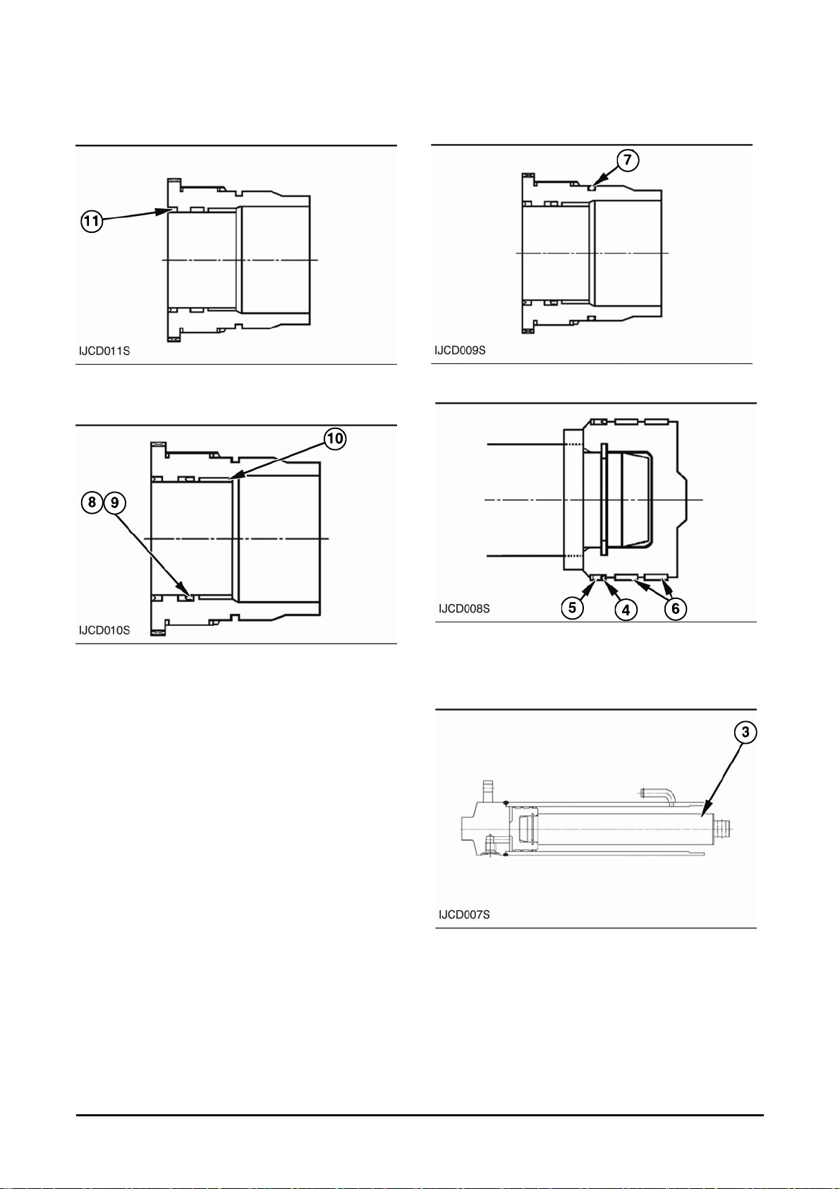
3. Remove rod (3) from the cy linder body .
4. Remove U-packing (4) , back up-ring (5) and wear
rings (6) from the pis ton.
5. Remove O-ring s eal ( 7) from the head as s em bly .
6. Remove wiper seal (8) and U-packing (9) from
the head assembly.
7. Inspect bushing ( 10) in the head assembly. If the
bushing has a large amount of wear, make a
replacement of the bushing and head as a unit.
The parts can not be order ed s epar ately.
8. Remove dust wiper seal (11) from t he head and
discard it.
Vehicle System Disassembly & Assembly 23
Page 26
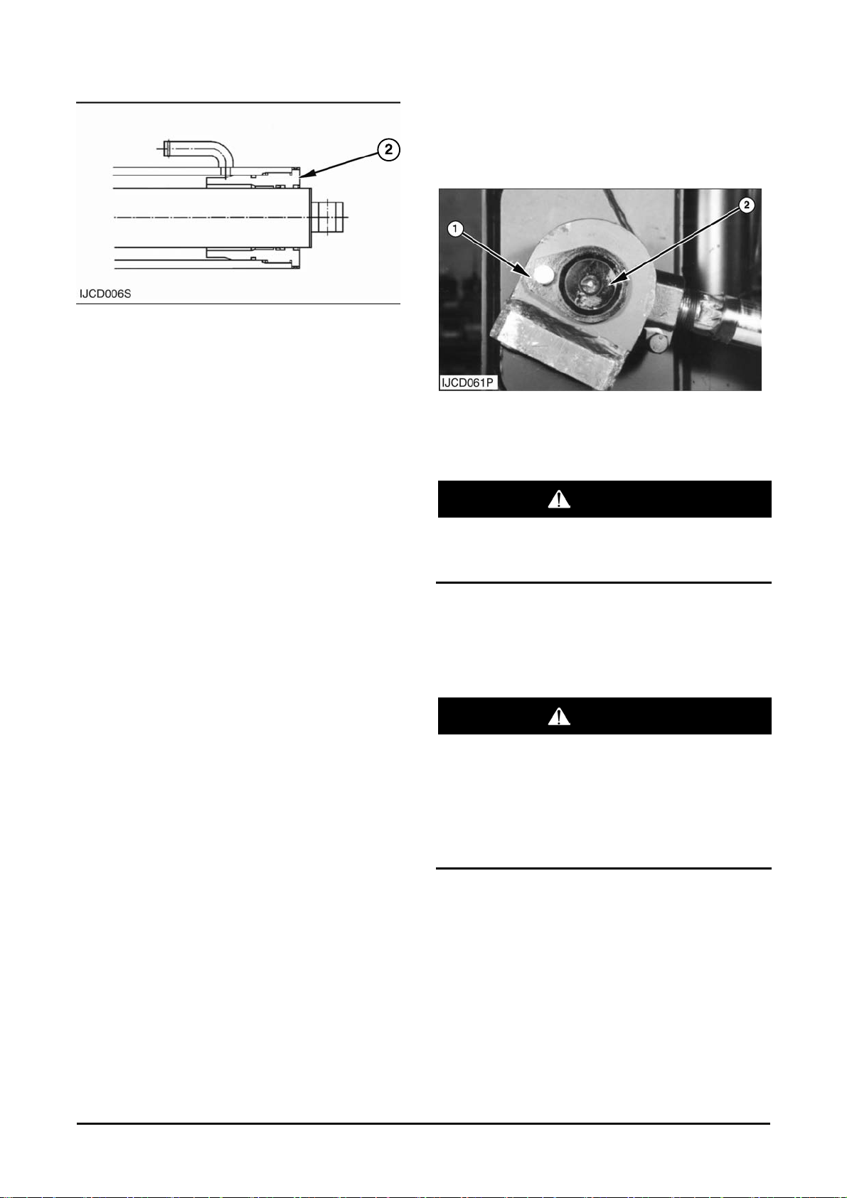
Assembly
1. Install dust wiper s eal ( 11) in the head.
2. Install bushing (10) and U-packing (9).
NOTE : U-packing (9) s hould be ins talled with the lip
of the seal toward the out s i de of t he head.
3. Install wiper seal ( 8) .
4. Install O-ring s eal (7) onto the head assembly.
5. Install wear rings (6), back-up ring (5) and U-
packing (4) on the piston.
6. Install rod (3) in the cylinder body.
Vehicle System Disassembly & Assembly 24
Page 27
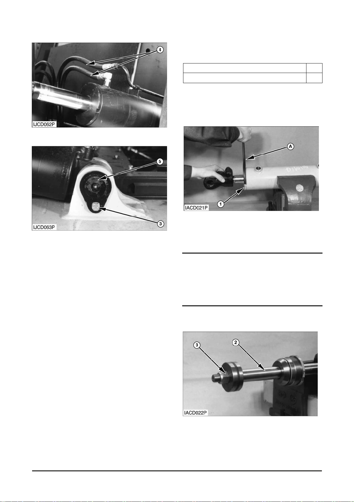
7. Install head assem bly (2) on the cylinder rod and
tighten it using t ool.
End By :
a. Install lift cylinders.
Tilt Cylinder
Removal & Installation
1. S tart the engine. Tilt the mast forward until rod
end pin (2) can be removed. Stop the engine.
WARNING
If both tilt cylind ers are to be removed, fasten a
hoist to the mast and put a support in position
under each side of the mast.
2. Fasten a hoist to the t ilt cy linder . Remove
retaining bolt (1), washer and rod end pin (2).
Start the engine. Mov e the r od into the cylinder.
Stop the engine.
WARNING
To prevent person al injury, make sure pressure
in the hydraulic system has been released
before disconnectin g any hydraulic lines. Slowly
loosen the cap of the hydraulic tank to release
any pressure in the tank. Be cautious of hot
hydraulic oi l when any lines are discon nected in
the hydraulic syst em.
Vehicle System Disassembly & Assembly 25
Page 28
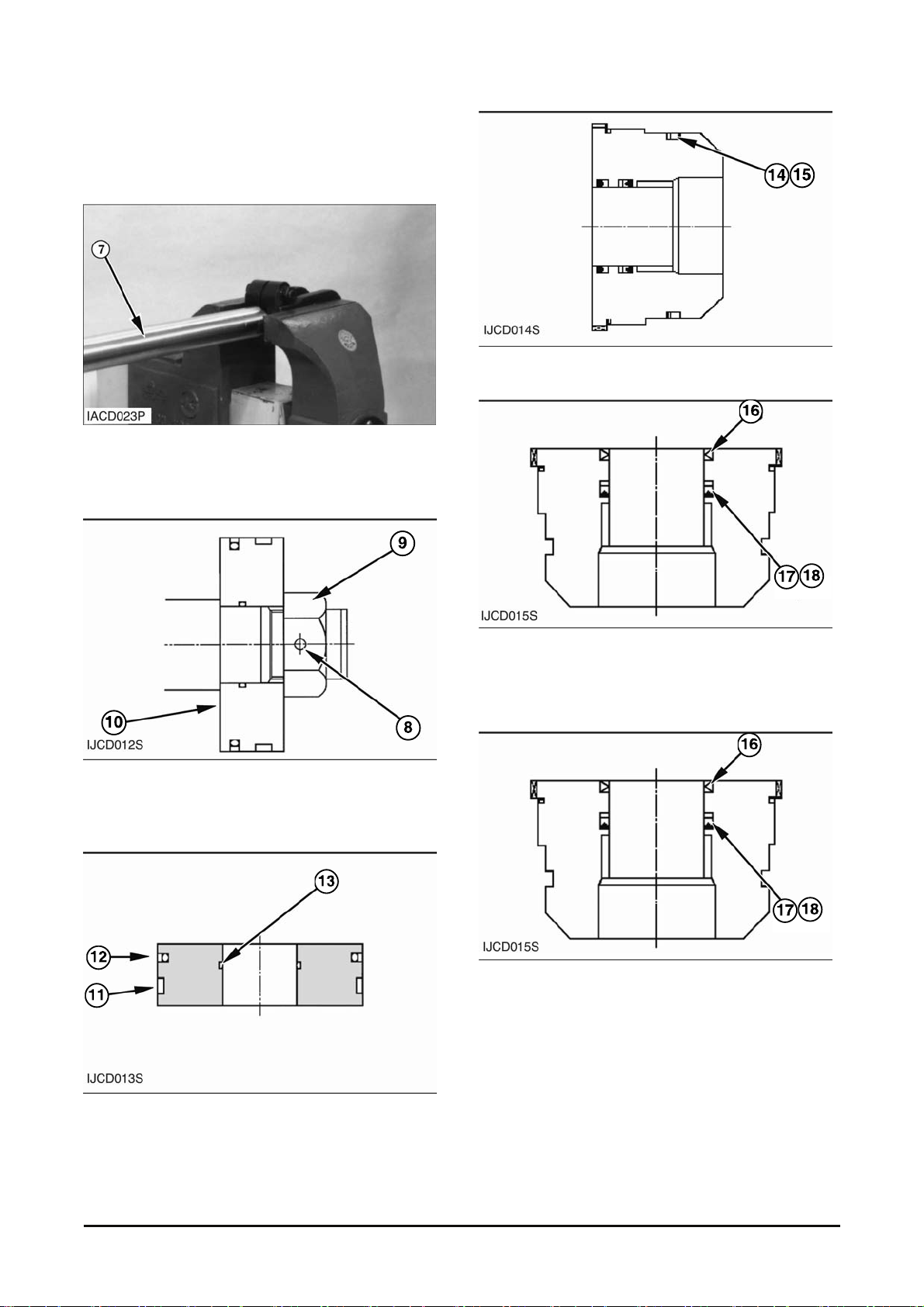
3. Disconnect oil lines (4) from the tilt cylinder.
4. Remove retaining bolt ( 3), washer and head end
pin (5).
5. Remove the tilt cylinder. The weight of the tilt
cylinder is 34 kg (75 lb).
NOTE : The following steps are for installation of the
tilt cylinder.
6. Fasten a hoist to the cylinder. Put the cylinder in
position on the fram e.
7. Install head end pin (5), r etainer and bolts.
8. Connect oil lines (4) t o the cylinder.
9. Start the engine. M ove the rod out of the cylinder
until rod end pin (2) can be installed. Stop the
engine.
10. Ins tall pin (2), retainer and bolts .
NOTE : Check the adjustment for the tilt cylinders.
Loosen the nut that holds the clevis in position on
the end of the rod. Move the clevis in or out until
both tilt cylinder s are the same length and t he mast
is at the correct angle in the “Tilt Forward” and “Tilt
Back” positions. See Tilt Cylinder Adjustment in
Testing And Adjusting.
11. Start the engine. Run the cylinders through full
strokes to remove the air from the hydraulic
system. Stop the engine. Add oil to the hydraulic
tank if needed.
Disassembly & Assembly
Tools Needed A
Spanner Wrench
Start By :
a. Remove tilt cy linder .
Typical Example
1. Use tool (A) to rem ove head (1) from the cylinder
body.
NOTICE
Use extra care not to damage the highly finished
surface of the cylinder rod and the bore of the
cylinder body during disassembly and assembly of
the tilt cylinder.
2. Remove rod assembly ( 2) from the c y linder body .
Typical Example
3. Remove nut (3) from the cy linder r od.
Vehicle System Disassembly & Assembly 26
Page 29
4. Remove the piston and seal assembly from the
cylinder rod.
5. Remove the head assembly .
Typical Example
6. Loosen the nut and bolt on the r od eye. Remove
cylinder rod (7).
7. Remove pin (8) to remove nut (9) from the rod.
8. Remove piston assem bly (10) from the rod.
9. Remove slipper seal (11), wear-ring (12) and O -
ring seal (13) from the piston.
10. Remove O-ring seal (14) and back-up ring (15)
from the head.
11. Remove wiper seal (16), U-packing (17) and
back up-ring (18) f r om the head.
NOTE : Use the following s teps to assemble t he tilt
cylinder.
NOTE : U-packing should be inst alled with the lip of
the seal toward the ins ide of t he head.
12. Ins tall U-packing (17) in the head. Position the lip
of the seal toward the inside of the head as
shown.
13. Inst all bac k up-r ing ( 18) .
14. Inst all s eal ( 16) in the cylinder head. Position t he
lip of seal (16) towar d the out s ide of the cylinder
head.
Vehicle System Disassembly & Assembly 27
Page 30
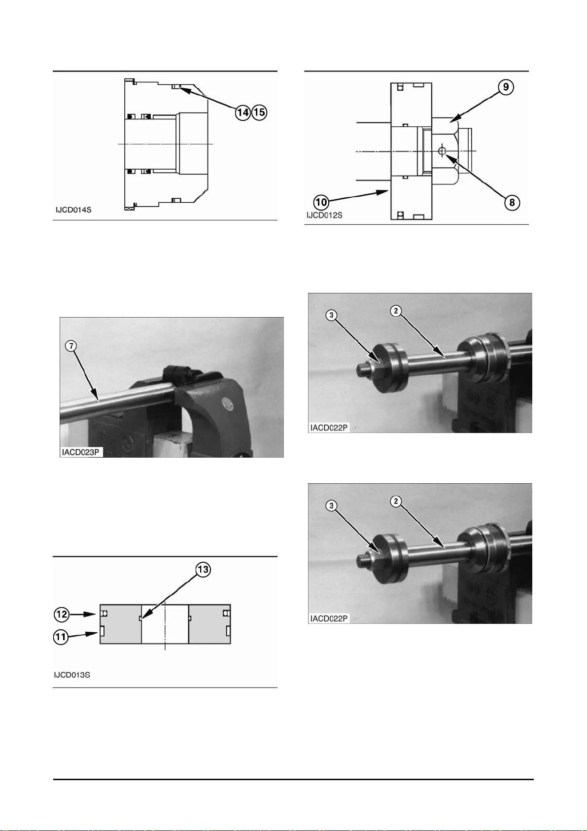
NOTE : The curved side of back up ring (15) should
contact O-ring s eal ( 14) .
15. Inst all O-ring seal (14) and back-up ring ( 15) as
shown. Make sure the curved side of back-up
ring (15) is in contac t wit h O-r ing s eal ( 14) .
Typical Example
16. Install cylinder rod (7). Tighten the nut and bolt
on the rod eye to a torque of 160 ± 30 N•m (118
± 22 lb•ft).
17. Ins tall head assembly (5) on the cylinder r od.
18. Install slipper seal (11), wear-ring (12) and O-
ring seal (13) on the piston.
19. Inst all pis ton assembly (10) onto the cylinder r od.
20. Install nut (9). Tighten nut (9) to a torque of 270
± 30 N•m (200 ± 22 lb•ft). Install pin (8).
Typical Example
21. Inst all r od as s em bly ( 2) in the cylinder body .
Typical Example
22. Use tool (A) to tighten head (1). the torque for
head (1) is 620 ± 80 N•m (458 ± 60 lb•ft) .
End By :
a. Install tilt c y linder .
Vehicle System Disassembly & Assembly
28
Page 31
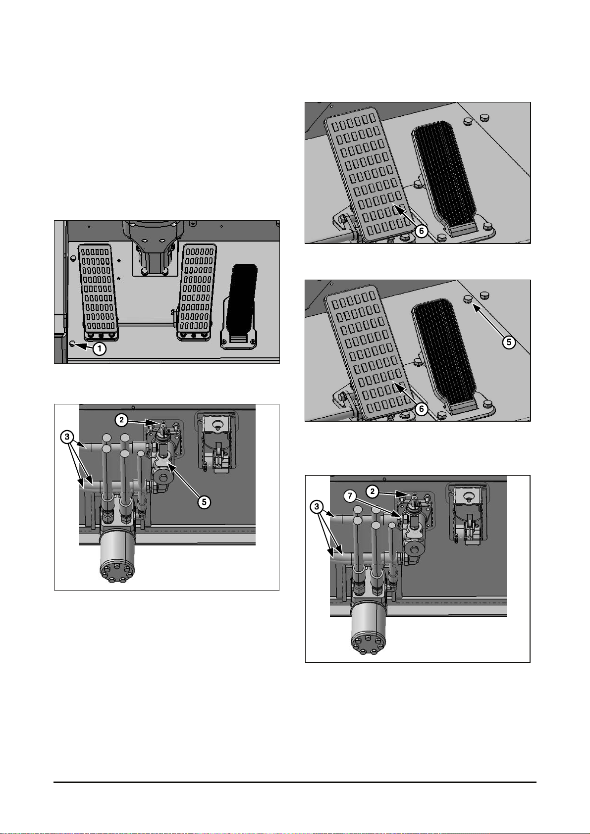
Brake Assembly
Removal & Installation
1. Put identification on the electric wires and hose
assemblies as to their location on the brake valve
for correct installation.
2. Press brake pedal 30t imes f or remove (bleed) the
pressure from the brak e system.
3. Rem ov e B olts (1) from the pedal plate.
4. Disconnect wiring har ness conn ector (2) f rom the
connect.
5. Disconnect hose (3) from the adapters of the
brake valve (5).
6. Remove brake as s em bly (6) from the floorplate.
7. Put brake assembly in position as a unit. Install
bolts (5) and washers that hold the brake valve
on the machine.
8. Install t he ( 7) adapter s to the brake valve.
9. Connect hoses (3) to the adapters.
10. Connect wir ing har nes s c onnec tor (2).
Vehicle System Disassembly & Assembly 29
Page 32
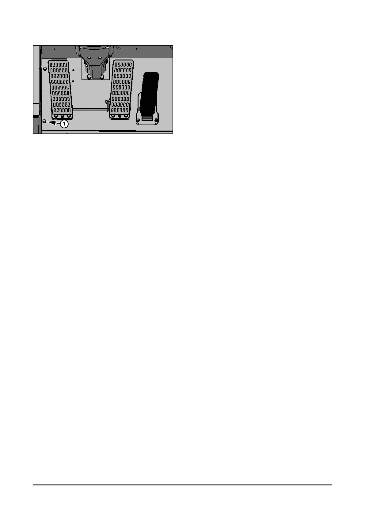
11. Ins tall plates (1) on the pedal plate.
Vehicle System Disassembly & Assembly
30
Page 33
Remote Control Valve
Operation
Max input pressur e r ange s hould be between 30 ~
100 bar (435 ~1,450 psi)
Back pressure of t ank port s hould be les s than 3 bar
(43.5 psi).
The oil temperat ur e s hould be between -10˚C~80˚C.
And, ambient tem perature should be from -40˚C ~
60˚C because the very high vis c os ity of oil will caus e
the defect of spool operation. Warm up the machine
to avoid it.
Tools needed for reworki ng
3 mm wrench.
13 mm socket spanner.
Torque wrench adjust able from 10 to 30 N·m.
Replacing the part s
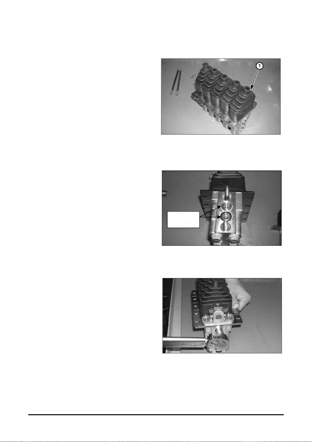
1. Replac ing a wor k ing s ec tion (1)
- Loosen two tightening bolts with 13mm socket
spanner.
O-ring
- Take out the damaged sec tion and inser t new one.
Pay attention to two O-rings on the internal
passage to be in right position.
- Tight M13 nut with proper t or que 30 Nm.
Vehicle System
Disassembly & Assembly 31
Page 34
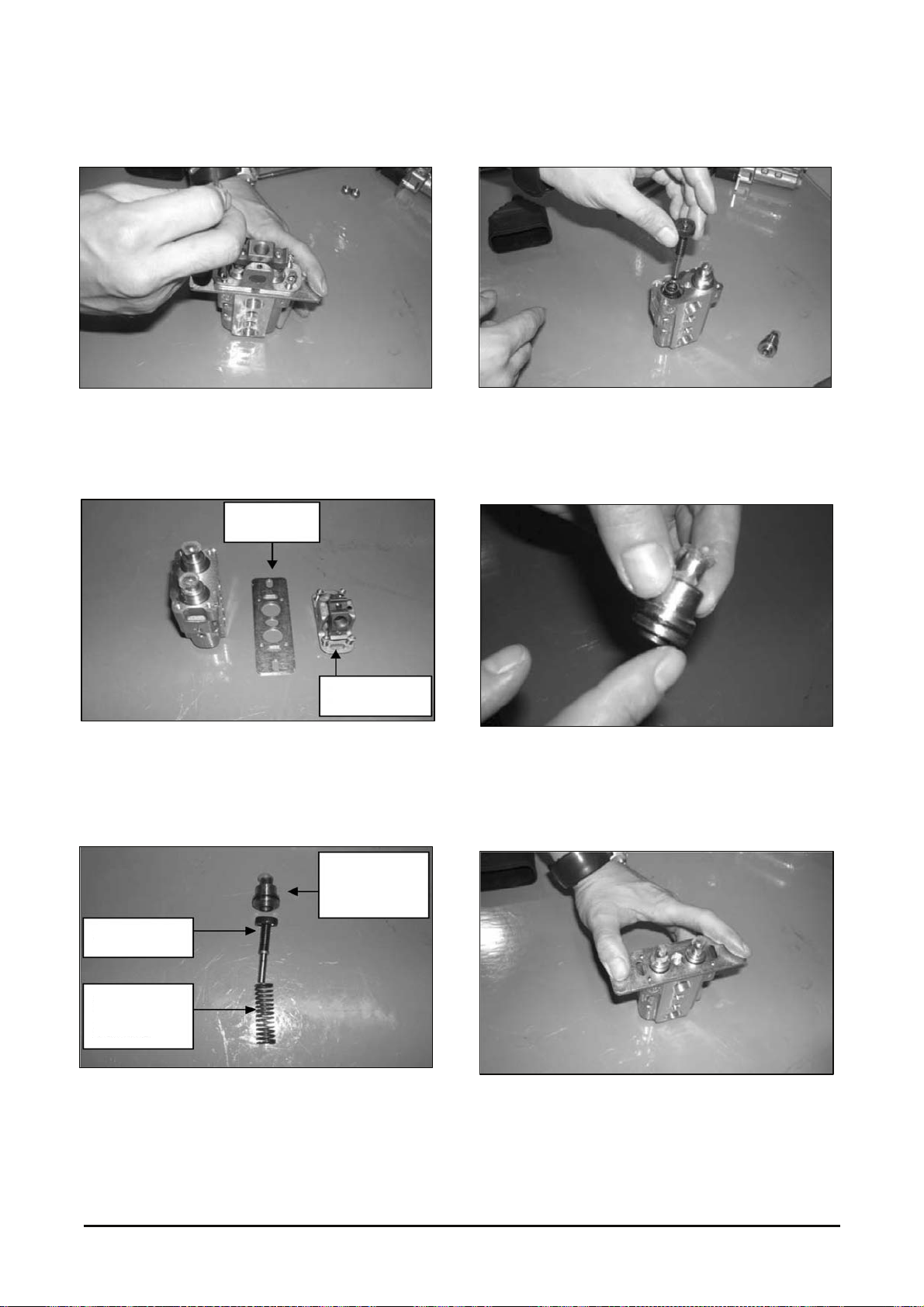
2. Replac ing P ilot Pressure Spool
- Loosen 4 screws holding upper par t to the body
with 3mm wrench. Hold mount ing plate not to
spring up by return s pr ings ins ide.
Flange
Fulcrum
- Take off the fulcr um and mount the f lange v er y
carefully. Keep all c omponents in their original
positions.
- Reassemble the spool in opposite order
mentioned above. Ins ert spool as straight as
possible not to give any dam age on it while
inserting it into body .
- Prepare copper cap in c lean c ondition.
- Apply some clean greas e ar ound the O-ring on the
copper cap, in order to avoid any damage on the
O-ring while fitting it into body.
Copper
cap
Spool
Return
Spring
- Take out the s pool, return spring from the body. And,
- Hold mounting flange tightly and lay the fulcrum on
replace any component if required.
the flange and screw in clam p bolts in a crisscross
pattern. Clamp tor que is 6.6 N·m.
Vehicle System Disassembly & Assembly
32
Page 35
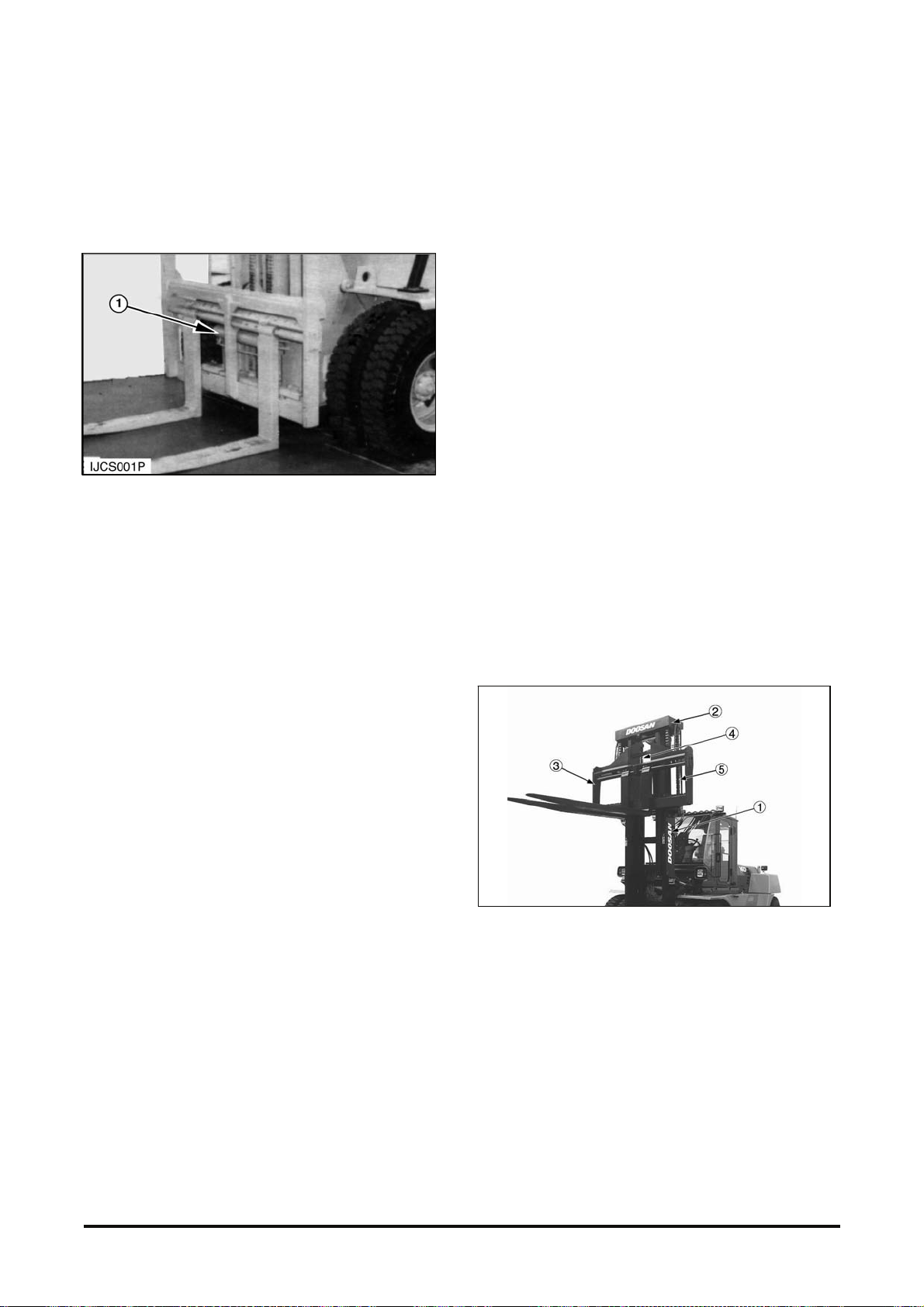
Attachment Carriage
If the lift truck is equipped wit h a s ides hifter carriage,
an extra valve spool is ins talled in the control valve.
Sideshifter Carriage
(1) Sideshifter cylinder.
When the valve spool is moved t o extend or retract
sideshifter cy linder (1), oil flows through the lines to
and from the control v alv e openings to move the
cylinder piston and rod. The cylinder moves the
carriage, either to the right or to the left. Sideshif t
hydraulic circuit has the same pressure relief v alv e
Lift Cylinder and Mast
The rods of lift cylinders ( 4) ar e moved up by
hydraulic oil pressure and r eturned to their original
position by gravity .
The single action of pilot lift cylinders together with
other mechanical lifting components will operate as
follows:
When the lift lever of pilot c ontrol valve is pulled
back, the hydraulic oil pressure pushes against the
inner pistons at t he bott om of the lift cylinders.
Inner mast (2) start t o move up.
At the same time, carriage (3) als o s tarts to move up
because it is connect ed to chains (5). Carriage (3)
moves at 2:1 ratio wit h the r ods of the lif t cylinders.
This movement of inner m ast ( 2) and carr iage (3)
goes on until lift cy linder s ( 4) are at the end of their
stroke.
as tilt circuit f or protection against an over load. A
check valve prevent s pressure oil through the
pressure outlet opening of the control valve from
returning under any cir c um s tance.
Lift Co m ponent
(1) Stationary mast. (2) Inner mast. (3) Carriage. (4) Lift cylinders.
(5) Lift chains.
Vehicle System
Disassembly & Assembly 33
Page 36
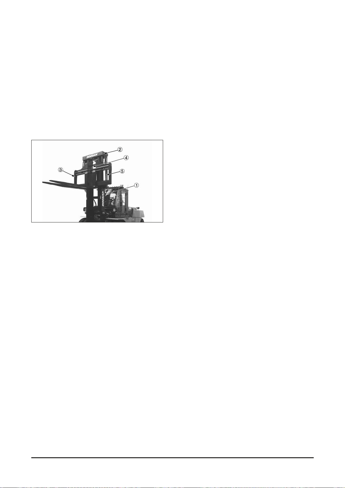
When the lift lever of pilot c ontrol valve is pushed
forward, the cycle t o lower the mast st arts. The
hydraulic oil pressure is r eleas ed from the lift
cylinder and the inner mas t and carriage lower by
gravity. The car r iage m ov es down at 2: 1 ratio with
the cylinder rods. The inner m as t mov es at the same
speed as the cylinder rods . This movement of the
mast and carriage goes on until the mast has
lowered completely and the forks are on the floor.
Lift Components (U p Position)
(1) Stationary mast. (2) Inner mast. (3) Carriage. (4) Lift cylinders.
(5) Lift chains.
The mast components ar e inner mast (2), stationary
mast (1), lift cy linder s ( 4) and lift c hains ( 5). The
mast assembly has mov em ent wit h upper and lower
load rollers installed on sealed bearings. Upper and
lower side thrust rollers control the side t hr ust
movement and are adjustable with shims.
Carriage (3) also has load roller s . The carriage side
thrust movement is also controlled by thrust rollers ,
which are adjustable with shim s.
Vehicle System Disassembly & Assembly
34
Page 37
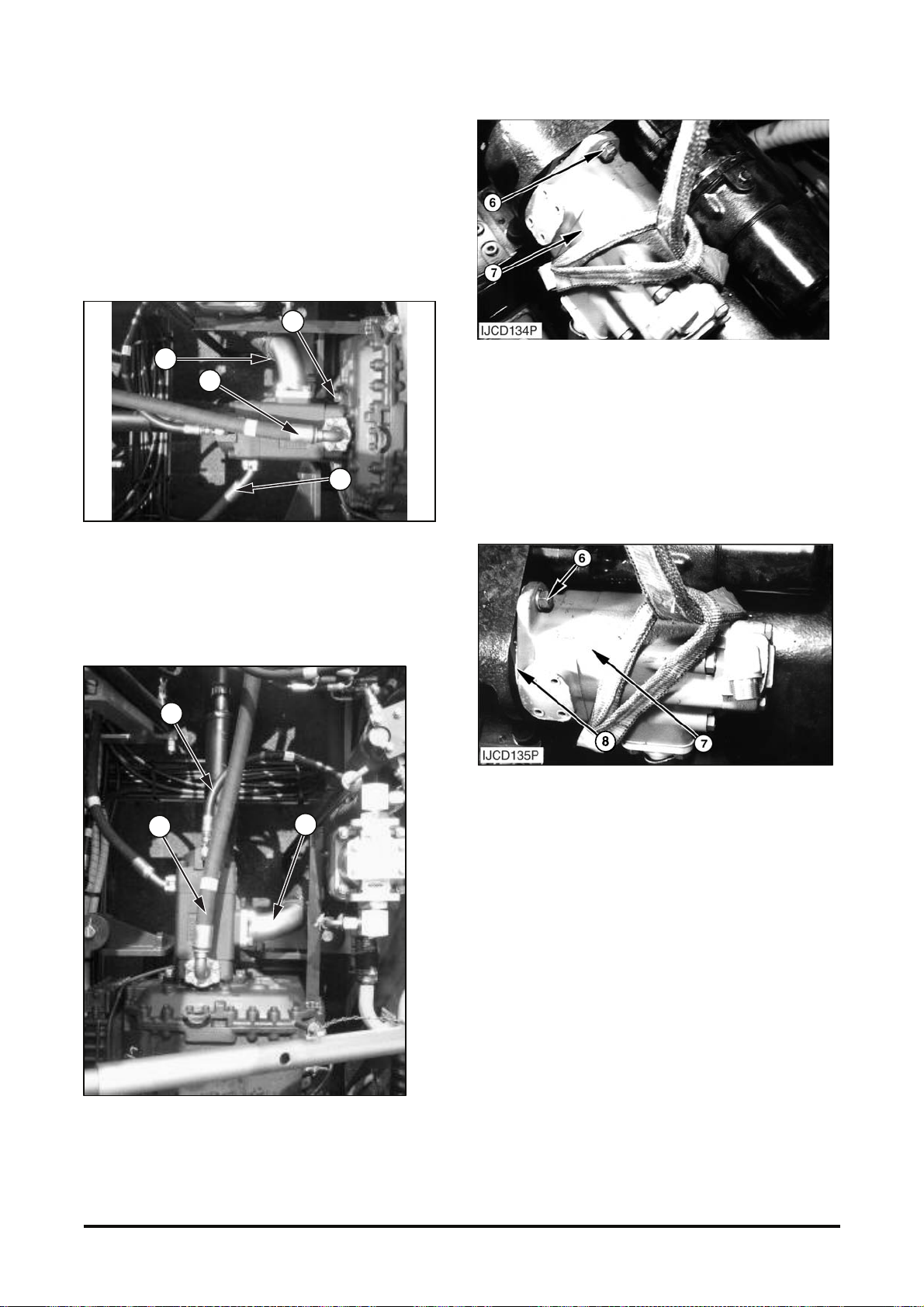
Hydraulic Pump
Removal & Installation
1. Drain the oil from the hydr aulic tank.
2. Tilt the cabin.
3. Disconnect three hoses and one tube from the
pump.
4. Loosen two clamps and disconnect suction hose
(5) from the flange.
5
2
4
2
1
3
5
5. Fasten a hoist to pump (7). Remove two nuts (6)
and lockwashers that hold the pump in place.
Remove the pump (7). The weight of the pump is
50 kg (110 lb).
6. Discard the gasket from the transmission case.
NOTE : The following steps are for installation of the
hydraulic pump.
7. Install new gasket (8) on the transmission cas e.
8. Fasten a hoist to pump (7). Put the pump (7) in
position and install the lockwashers and Bolt (6)
that hold the pump in place. The weight of the
pump is 50 kg (100 lb).
9. Connect suction hos e ( 5) to t he flange and tighten
the clamps.
10.Connect three hoses (3) and (4) to t he pump elbows.
11. Fill the hy dr aulic tank with oil to the correct level.
See the Operation and M aintenance Manual.
Vehicle System
Disassembly & Assembly 35
Page 38
Start-up Instructions &
Recommendations
Rotation & Ports Indication
The rotation and ports orientation are viewed from
the shaft end.
CW stands for clockwise, right-hand rotation.
CCW stands for counter-clockwise, left-hand
rotation.
Start-up :
The tank has been filled up with a clean fluid in
proper conditions.
Flushing the system with an external pump prior to
the start-up is good.
To allow a good priming of the pump, t he air should
be bled off.
The first valve on the cir c uit should be open to tank.
It is possible t o bleed off the air by creating a leak in
the P port of the pump.
Warning : this has to be done in low
pressure mode as it could create a
dangerous fluid leak. Make sure that the
pressure cannot rise (open center valve to tank,
pressure relief valve unloaded ...).
When oil free of air appears, tighten t he connectors
to the correct torque.
The pump should prime wit hin a few sec onds. If not,
please read the troubleshooting guide.
If the pump is noisy, please t roubleshoot the system.
Never operate the pum p at top speed and pressure
without checking t he c om pletion of pump priming.
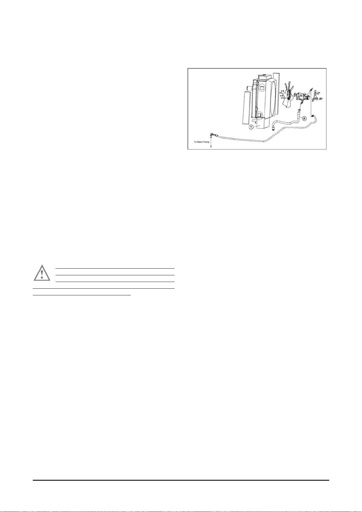
Removal of Air in Pump – Motor
line
If either main pum p or f an motor is replaced in the
field, be sure to apply the following bleeding
process:
1. Do not assemble the fan motor outlet hose A – at
this time.
2. A dd hy dr aulic oil in the tank. This will fill the
components and hoses displac ing any air until oil
begins to drain from the out let port.
3. A s s em ble the hose to the pump outlet.
4. Turn on the engine and keep it idle f or 3-5
minutes.
Vehicle System Disassembly & Assembly 36
Page 39
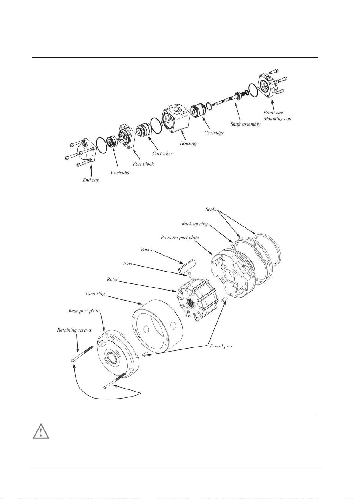
Pump & Cartridge Breakdown Drawing
The purpose of the two screws is just t o hold the cartr idge together. When tightening t hem, chec k the
rotation of the rot or & vane assembly.
Vehicle System Disassembly & Assembly 37
Page 40

Disassembly
1. Install the pum p on the t able.
4
Two bolts in the front c ap will help to unscrew the (4)
pump bolts.
2. Unscrew the bolts .
Vehicle System Disassembly & Assembly 38
Page 41

3. Rotate the end cap for a bett er prehension.
End Cap
4. Remove the end c ap ( P 3 cart ridge).
P3 Cartridge
If the floating port plat e stays in the end cap,
please use two screws to t ak e it out.
Pull the 2 screws together.
Vehicle System Disassembly & Assembly 39
Page 42
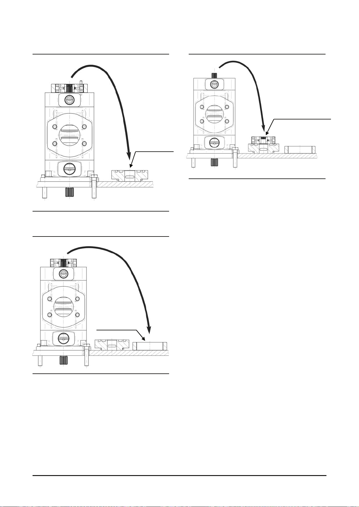
5. Rem ov e the rear port plate.
Rear port plate
6. Rem ov e the camring and the dowel pin.
Cam ring
7. Remove the r otor & vane assembly.
Rotor & Vane assembly
Vehicle System Disassembly & Assembly 40
Page 43
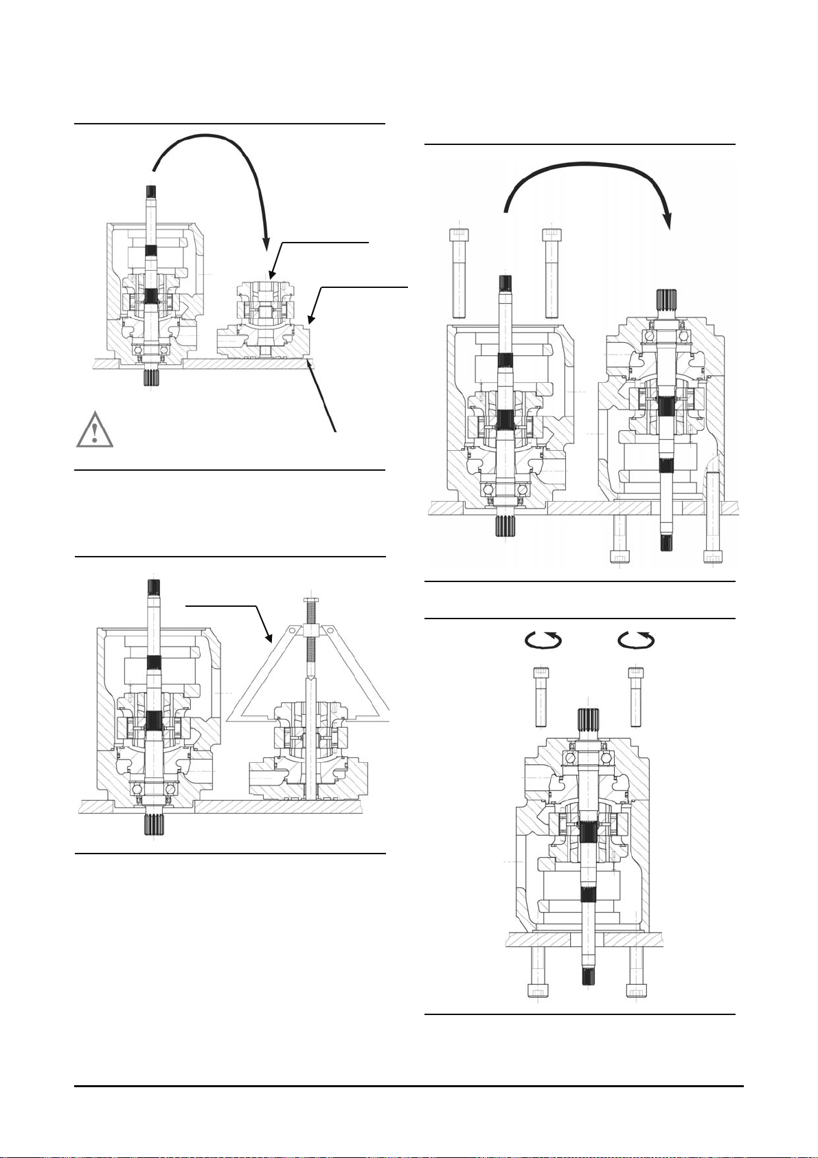
8. Remove the P2 cartr idge / port block.
P2 Cartridge
Port block
Be carefull to the cleanness of the surface.
9. Disassemble the P2 c artridge / port block wit h an
extractor.
Extractor
If you want t o continue t he pump disas sembly (P2 &
shaft), go to next page.
If you want to reassemble the P2 cartridge, go to
page 51.
10. Put two screws in the housing and f lip the pum p
(housing + P1 assy).
11. Remove the 4 front bolts.
Vehicle System Disassembly & Assembly 41
Page 44
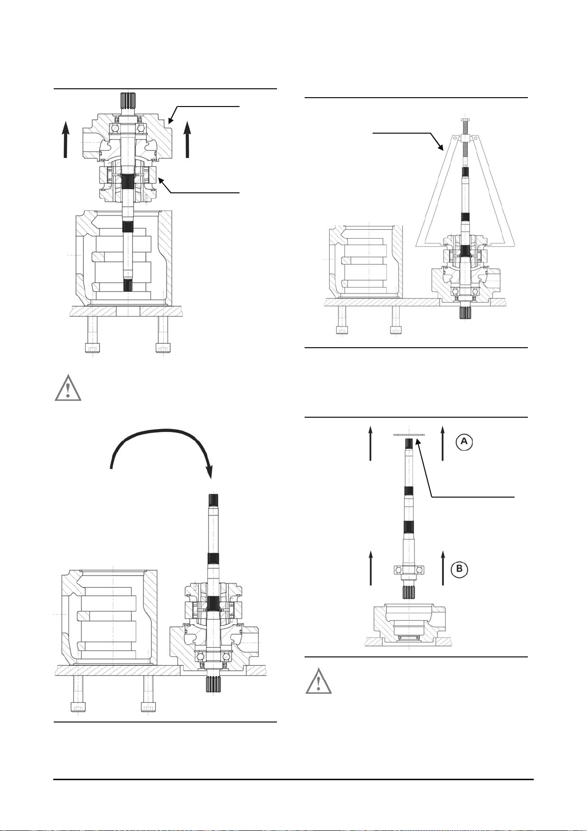
12. Remove the front cap.
P1 cartridge will come with the front cap /
shaft assembly.
Front cab
P1 Cartridge
13. Disassemble the P1 cartridge / front c ap with an
extractor.
Extractor
If you wish to convert the cartridge, go to page 14.
A : Remove the retaining ring
B : Extract the shaft / bearing ass em bly
Retaining ring
Take a protection cone to prevent seal
damage (dim. page 55).
If you don’t, change t he s haft seal.
If not new, the shaft seal should be r eplac ed.
Vehicle System Disassembly & Assembly 42
Page 45
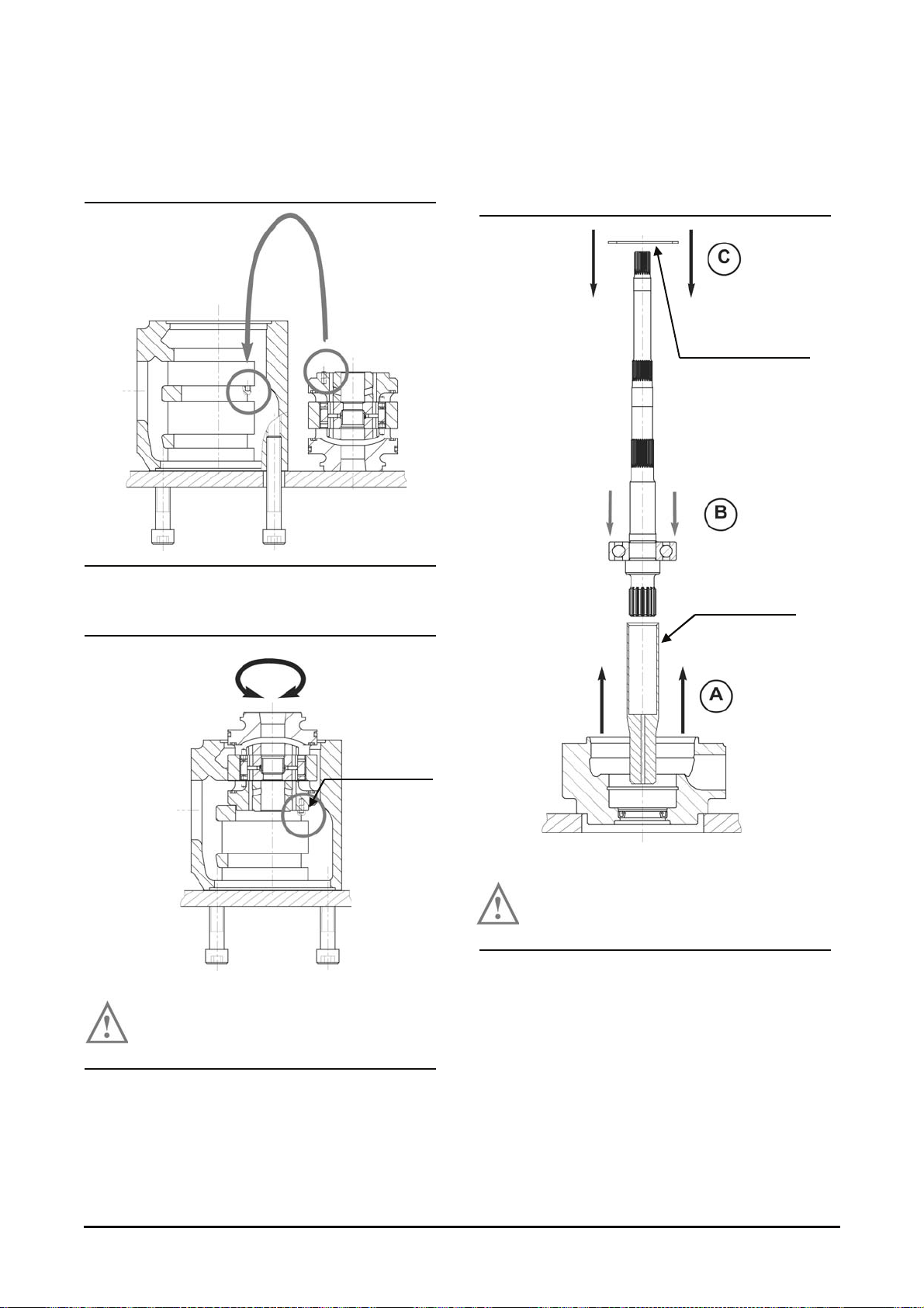
Reassembly
1. Fit the cartridge ( P 1) into the housing.
2. Check if the dowel pin is in its position in the
housing by trying to rotate the cartridge.
If the cartridge does rotate, the dowel pin is
not in the hole. Tak e the cartridge out and
try again.
Dowel pin
A : Protective cone on the shaft assembly
(dimensions per shaf t in page 55).
B : Shaft assembly + prot ectiv e c one into the front
cap
C : Retaining ring.
Push on the external bear ing “cage”.
To avoid damaging the shaft seal do not
forget to put a protect i v e c one on the shaft .
Retaining ring
Protective cone
Vehicle System Disassembly & Assembly 43
Page 46
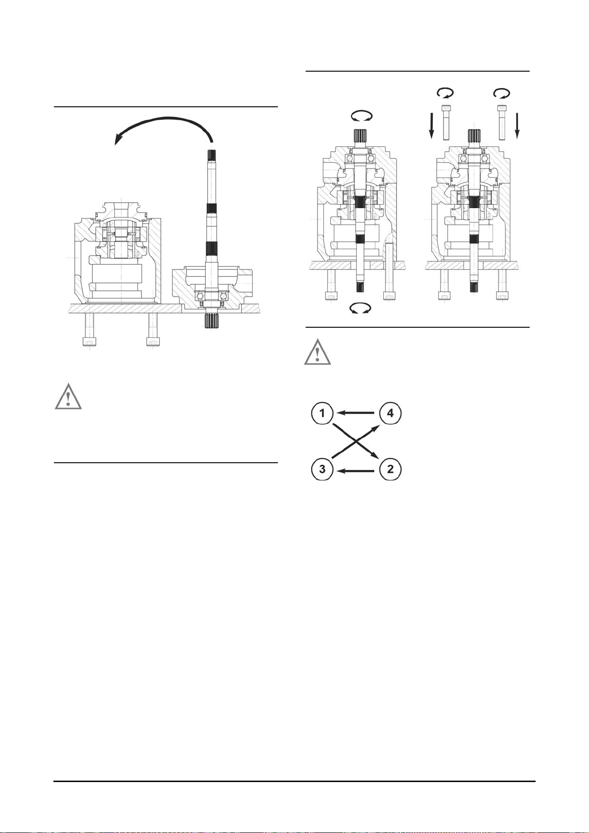
3. Assemble the front cap assy on the housing &
cartridge assy.
Position the shaft / front cap assy only if the
cartridge is well posit ioned, dowel pin in the
housing dowel pin hole.
Put some grease on the seals to prevent them from
moving.
a) Always check if the shaft rotates freely.
If not, disassemble and go back to the
previous step.
b) Tighten the 4 bolts. Tor que is 110 N•m ( 81 lb•ft)
Step by step to avoid
damaging the seals.
c) Always check if the shaft r otates freely.
If not, disassemble and go back to the previous
step.
Vehicle System Disassembly & Assembly 44
Page 47
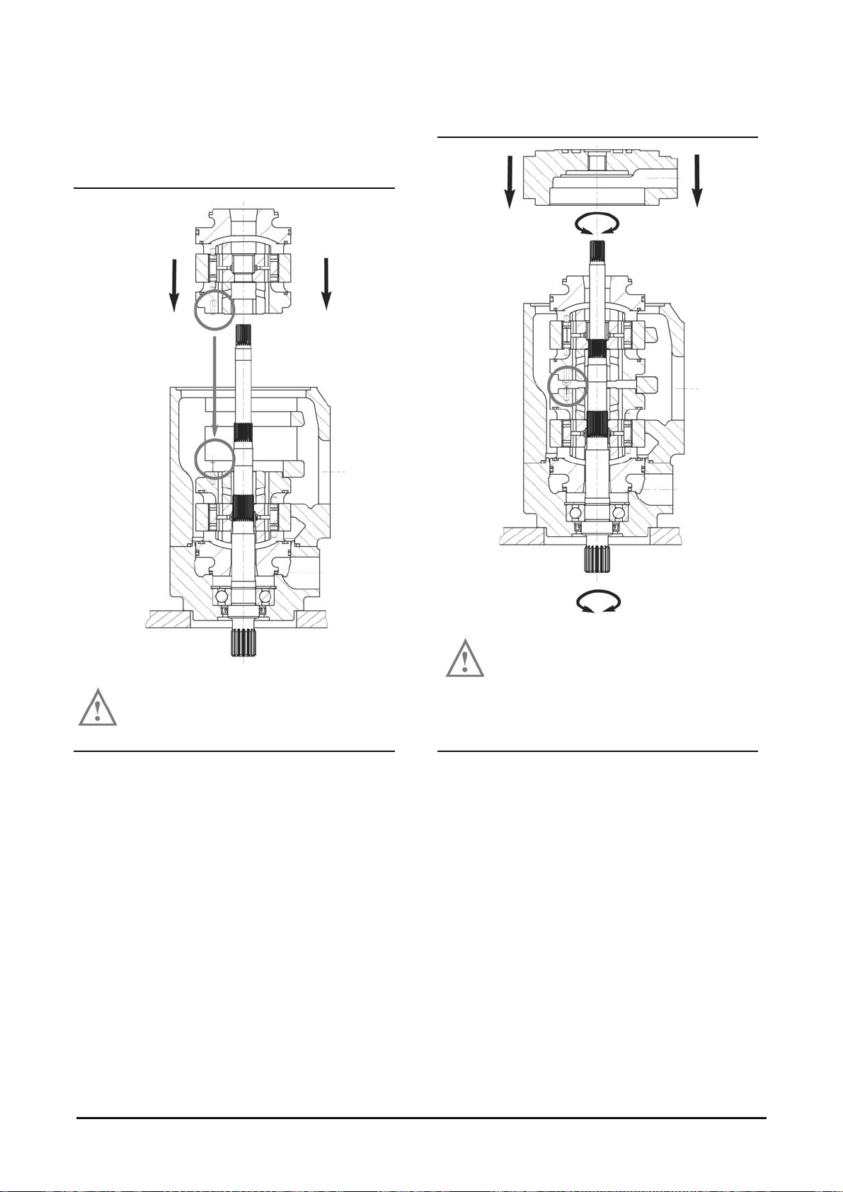
4. Fit the cartridge ( P 2) into the housing.
5. Chec k if the dowel pin is in its position in t he
housing by trying to rotate the cartridge.
If the cartridge does rotate, the dowel pin is
not in the hole. Tak e the cartridge out and
try again.
6. Assemble the port block on the housing assy.
Put some grease on the seals to prevent
them from moving.
Always check if t he shaft rotates freely.
If not, disassem ble and go back t o the previous s tep.
Vehicle System Disassembly & Assembly 45
Page 48
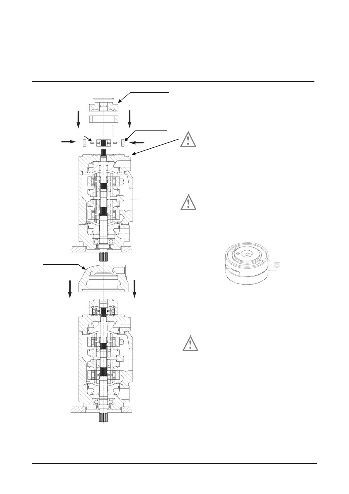
7. Install the rot or / pin / vane assembly.
Install the dowel pin.
Install the cam ring.
Install the rear port plate.
Rear port plate
Dowel pin
Cam ring
End cap
8. Assemble the end cap on the port block.
The surface must be clean.
Be sure that the port plate / cam ring are
assembled with a good concentricity (to
allow the end cap to fit cor-rectly.)
Always check if t he shaft rotates freely.
If not, disassemble and go back to the
previous step.
Vehicle System Disassembly & Assembly 46
Page 49
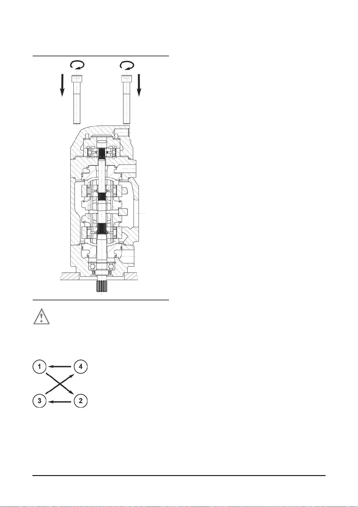
9. Final assy.
a) Always check if the shaft rotates freely.
If not, disassemble and go back to the
previous step.
b) Check the porting c onfigur ation (refer to page 30).
c) Tighten the 4 bolts. Torque is 190 N•m (140 lb•ft)
Step by step to avoid
damaging the seals.
d) Always check if the shaft rotates freely.
If not, disassemble and go back to the previous
step.
Vehicle System Disassembly & Assembly 47
Page 50
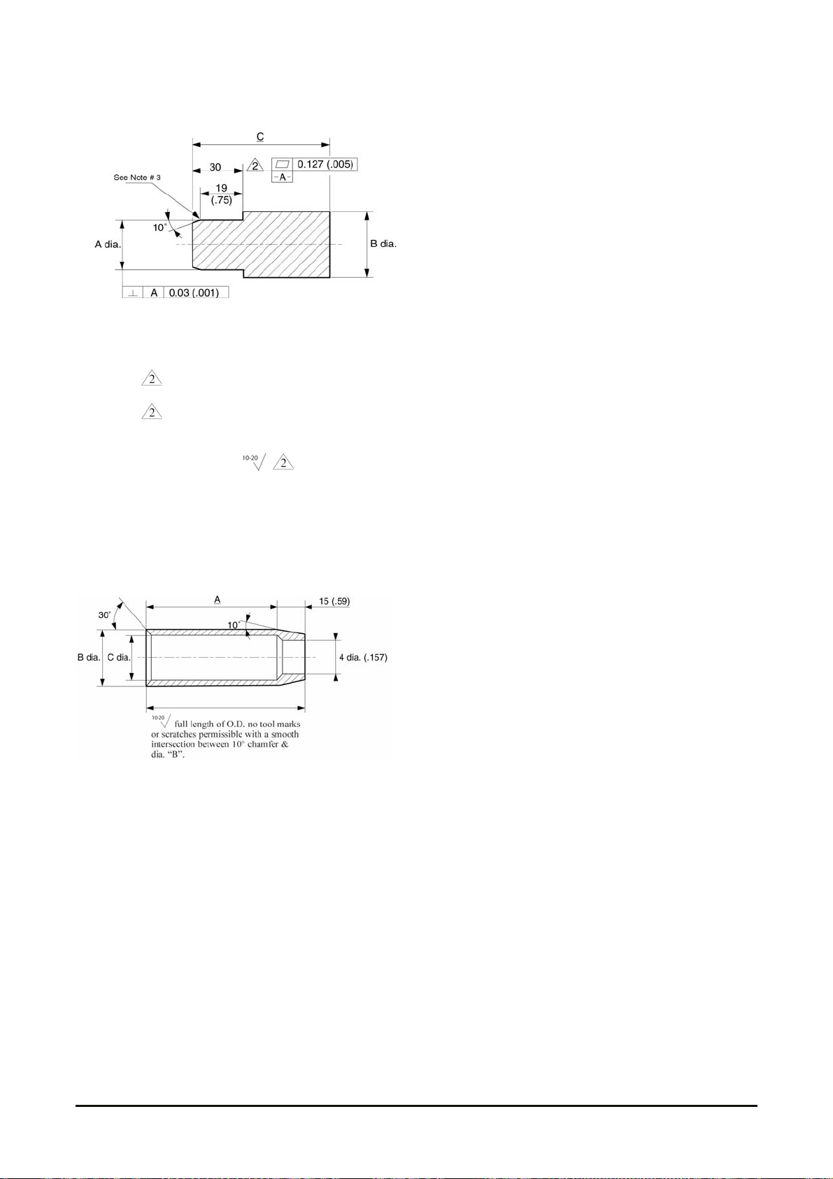
Seal Driver
1. B r eak s harp edges: 0.25/0.13 R (.010/ .005 R).
2. Length
3. Length
intersection bet ween c ham fer and dia. "A".
4. Grease O.D. of length
the shaft seal on the tool to prevent damaging t he
seal.
Material 4140 or equivalent .
to be heat treated to RC 47/50.
to have a full length, with a smooth
before installing
Dimension of Protective Cone
NOTES :
1. Remove all burrs and break sharp edges:
0.25/0.13 R (.010/.005 R).
2. Teflon preferred, alternate 4140 treated after
machining to RC 50-55.
3. Install protective cone over shaft extension and
grease O.D. to prevent dam aging the shaft seal.
Vehicle System Disassembly & Assembly 48
Page 51
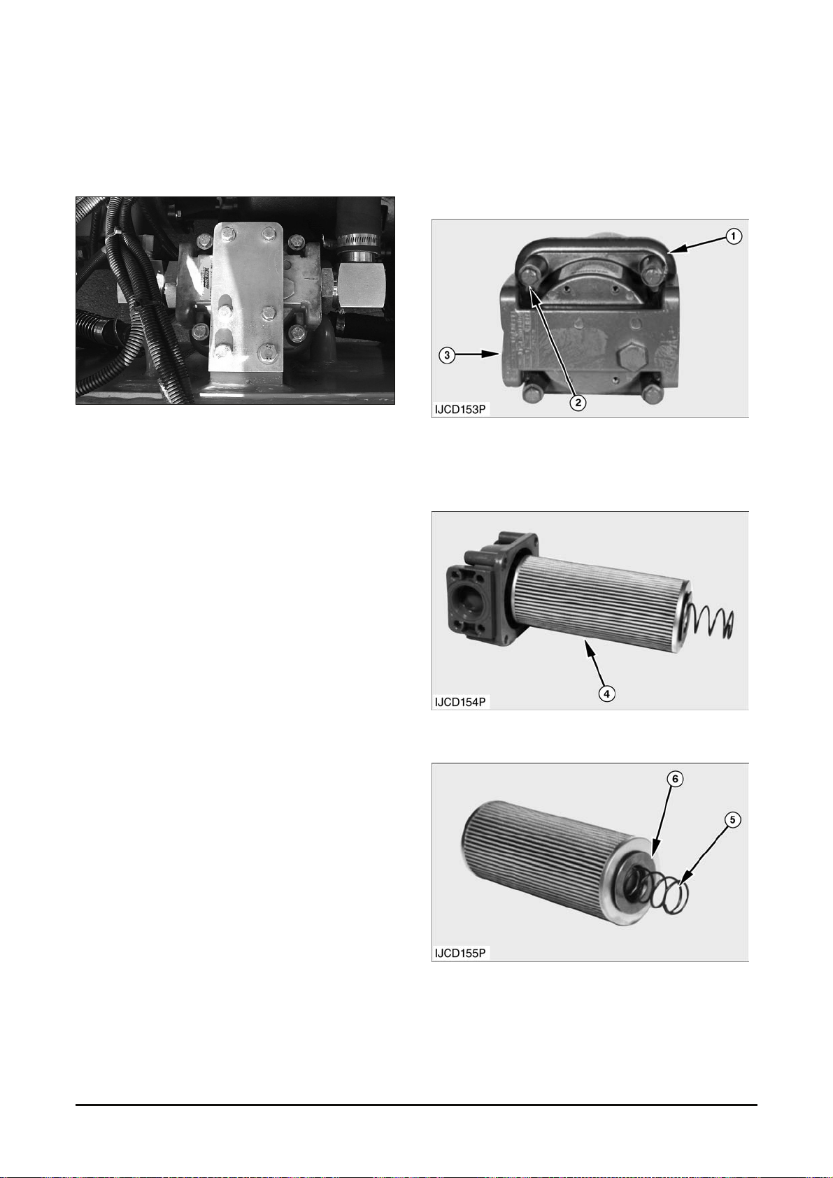
Hydraulic Oil Filter
Removal & Installation
1. Tilt the cabin. Ref er to page 25.
2. Dis c onnec t three oil lines (2)
3. Remove four bolts and was hers (1) that hold the
oil filter assembly to the truck. Remove the oil
filter.
NOTE : The following steps are for installation of the
hydraulic oil filter as s em bly .
4. P ut the hydraulic oil filter assembly in position of
the lift truck. Att ac h the hydraulic oil filter
assembly with four bolts and washers (1).
5. Connect three oil lines ( 2).
6. Return the cabin t o the f ix ed pos ition.
7. Fill hydraulic oil tank to the correct level. See the
Operation and Maintenanc e Manual.
Disassembly & Assembly
Start By :
a. Remove hydraulic oil f ilter assembly.
1. Remove four bolts (2) that hold housing (1) to
head (3)
2. S epar ate head (3) from housing (1).
3. Remove element (4) . Place elements (4) in pan to
eliminate dripping.
4. Remove spring (5) and s pr ing plate (6) from
element.
Vehicle System Disassembly & Assembly 49
Page 52

5. Clean enclosure bowl. Use lint free rag.
6. Inspect housing O-ring seal (7) for cut, nicks, etc.
NOTE : The following steps are f or the assembly of
the hydraulic oil filt er as s em bly .
7. Place element (4) on flat surface.
8. Place spring plate (6) and spring (5) in element
grommnet.
9. Place cleaned enclosure bowl over element.
10. Lubricate grommet.
NOTE : Small amount of drained oil from pan
applied with finger should suf fice.
11. Slide element over guide tube on filt er head.
12. At tach filter retaining ring and bowl as s em bly ,
tighten bolts (2) evenly. Avoid pinching O-ring
seal (7). Tor que r equir ed to tighten bolts (2) is 34
N•m (25 lb•ft)
End By :
a. Install hydraulic oil filter assembly.
Universal Joint
Removal & Installation
Start By :
a. Remove floorplate.
1. Fasten a strap to the universal joint. Remove four
bolts (1). Rem ov e the univer s al joint.
NOTE : The following steps ar e for the installation of
universal joint.
2. Install the universal joint wit h the bolt holes on the
yoke lined up with the pulley bolt holes .
3. Install f our bolts (1) with Loctite No. 242.
* Torque : 55 ± 7 N•m
End By :
a. Install floorplat e as s embly.
Vehicle System Disassembly & Assembly 50
Page 53

Disassembly & Assembly
Start By :
a. Remove universal Joint.
1. Remove cap (1).
2. Mark both yokes with an alignment mark for
future reference.
3. Pull yoke (2) from yoke (3).
4. Remove f elt seal ( 5), washer (4) and cap (1) f rom
the yoke assembly.
5. Check all parts of the drive shaft for wear and
damage. Use
NOTE : The following steps are for the as sembly of
the hydraulic pump driv e.
6. Put cap (1) and washer (4) into position on the
yoke assembly.
7. Install a new felt seal (5) on the yok e.
NOTICE
The flanges of t he two yokes c an be assembled out
of parallel. Wrong assem bly of the universal joint will
cause very short joint life.
8. Make an alignment of the marks on yokes (3) and
(2). The f langes on the yokes must be parallel to
each other.
9. Slide yokes (3) and ( 2) toget her .
10. Install cap (1) on to yoke (2).
End By :
a. Install universal joint .
Vehicle System Disassembly & Assembly 51
Page 54
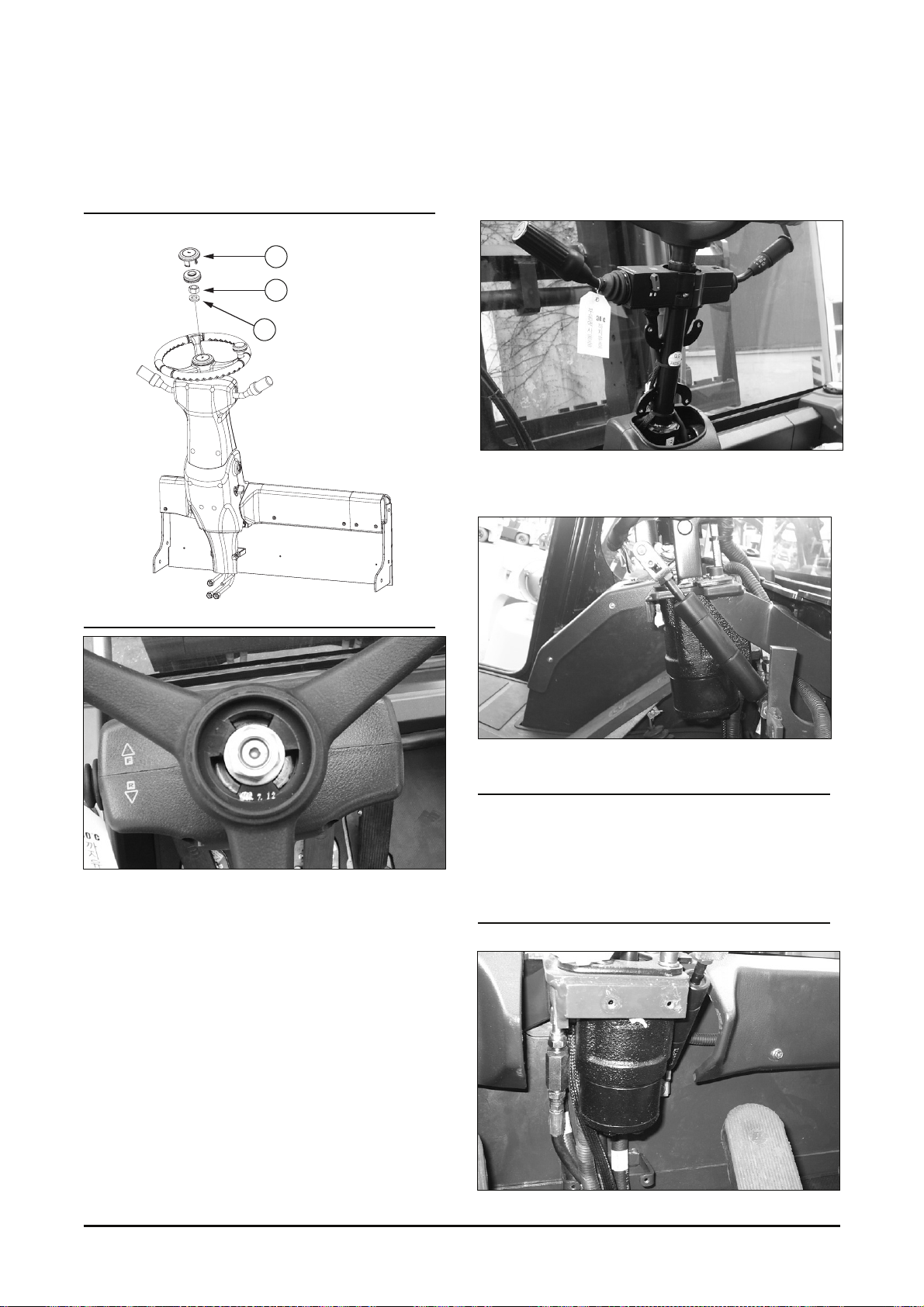
Steering Wheel & Gear
Steering Wheel
1. Remove cap (1) from the steering wheel.
2. Remove nut (2) and was her ( 3) fr om the steer ing
wheel.
3. Use a suitable puller to r emove the steering
wheel.
NOTE : The following steps ar e for installation of the
steering wheel.
4. P ut the steering wheel in position on t he s haft.
Install washer (3) and nut (2). Tighten the nut to a
torque 80 ± 7 N•m (60 ± 5 lb•ft).
5. Install cap ( 1) on the steering wheel.
1
2
3
Removed & Disassembly of
Steering Gear
1. Remove all covers ar ound the column.
2. Remove Switch Ass’y – F/ R and Swith A ss’y –
Combination.
3. Disconnect Gas spring and colum n A s s ’y .
NOTICE
Steering gear and column can separate after bolts
have all been removed, causing gear to fall. To
avoid damaging components, support the steering
gear while removing bolts.
Vehicle System Disassembly & Assembly 52
Page 55
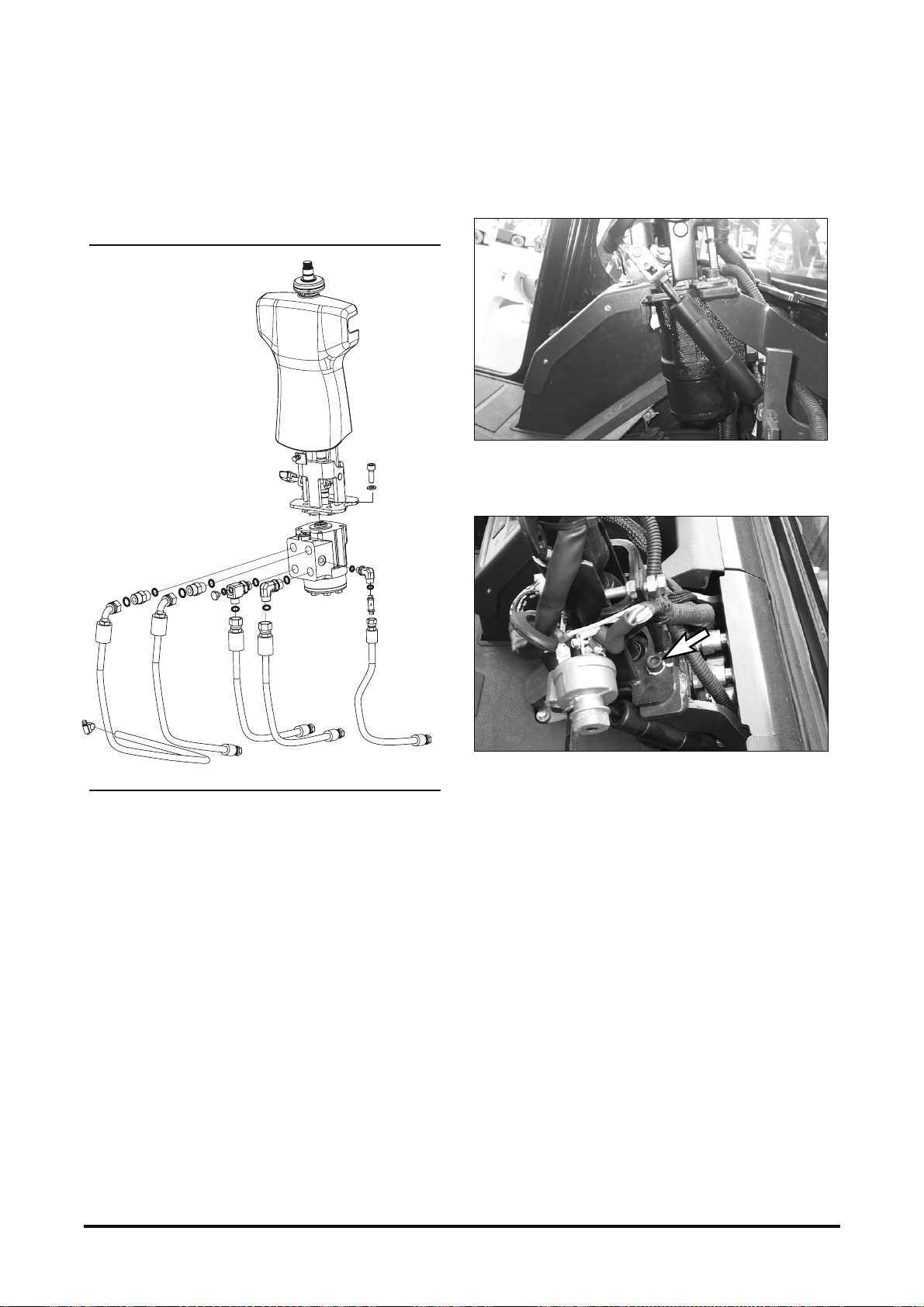
4. Disconnect ( 5) hoses as s em bled to steering unit.
NOTE: Put identification marks on all hoses for profer
installation. Plug and cap all openings to avoid
contamination and debris from entering the system
after removing any hoses or lines.
5. Disassemble s teering unit.
6. Install steering unit. Be sure to replace O-rings
with the new ones and apply the correct hose per
its labeling.
7. Assemble Gas Spring. Before inser ting Yoke onto
pin, apply the grease f or lubrication.
8. Mount Clumn Ass’y. The t or que of bolt is 30 N•m.
Vehicle System
Disassembly & Assembly 53
Page 56
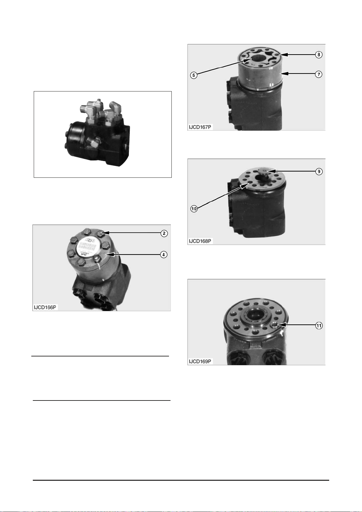
Assembly of Steering Gear
Start By :
a. Remove steering gear.
Typical Example
1. Put identific ation marks on the body f or assembly
purpose and remove fit tings (1) from the steering
gear.
2. Remove seven bolts ( 2) and washers.
3. Remove end cover (4) .
NOTICE
Make a note of the position of special bolt with a pin.
It is located at a mark in line wit h check valve.
4. Remove inner gear (5), and outer gear (7).
Remove the O-ring seal (8) from the outer gear.
5. Remove shaft (9) and distributor plate (10) from
the body.
6. Screw out the threaded bush (11) over the check
valve.
Vehicle System Disassembly & Assembly 54
Page 57
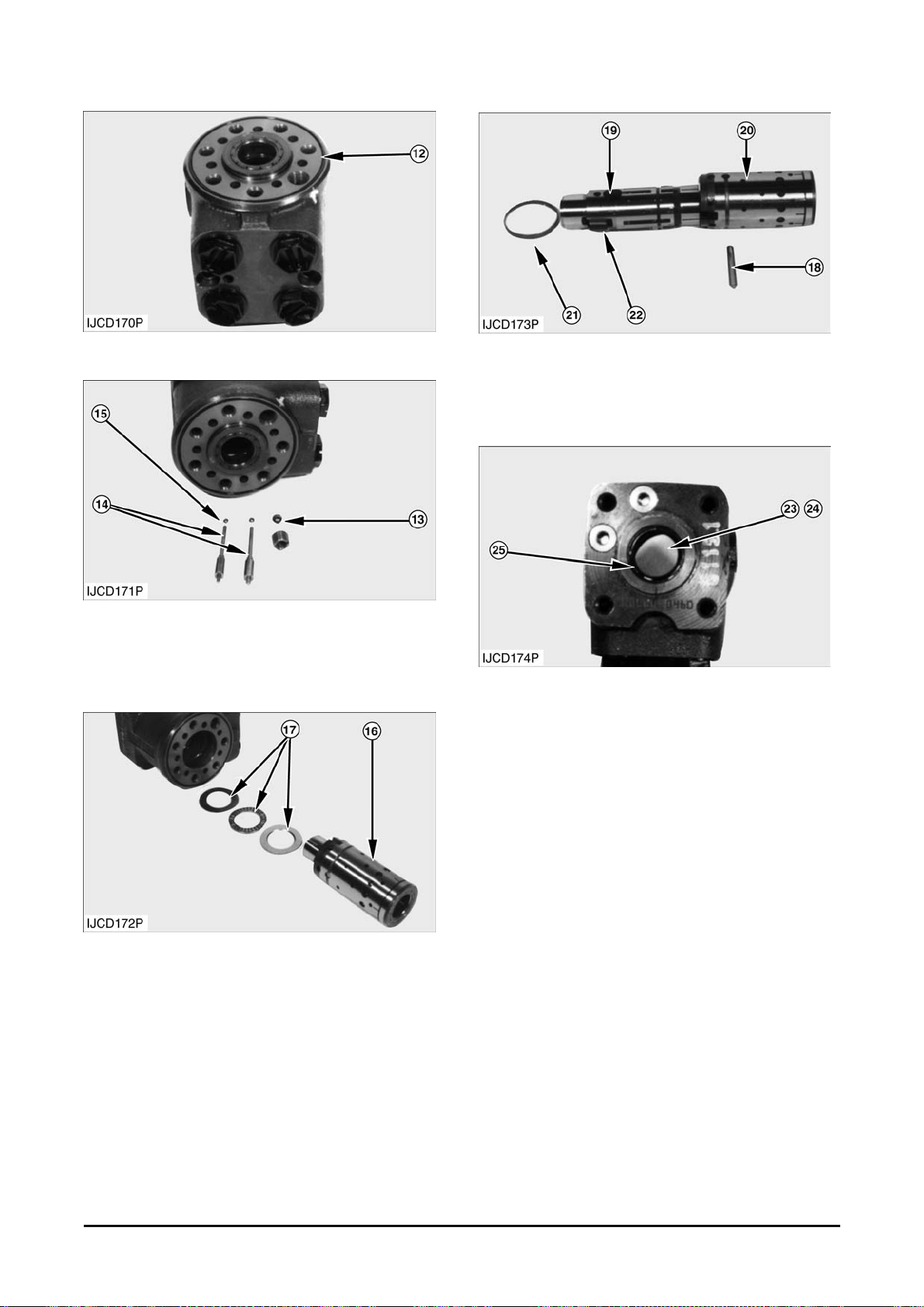
7. Remove O-ring s eal ( 12) .
8. Remove check valve ball ( 13).
9. Remove pins (14) and suc tion valve balls (15).
10. Remove s pool as s em bly ( 16) and bearing set
(17).
11. Remove pin ( 18) that holds inner spool (19) in
outer spool (20). Rem ov e inner s pool ( 19) and
remove ring (21) f r om the outer s pool. Remove
springs (22) fr om inner spool ( 19) .
12. Remove O- r ing s eal ( 23) and k ing-ring (24) from
body (2).
13. Check the condition of lip seal (25) . Repalce
seals with new one if worn or damaged.
Vehicle System Disassembly & Assembly 55
Page 58
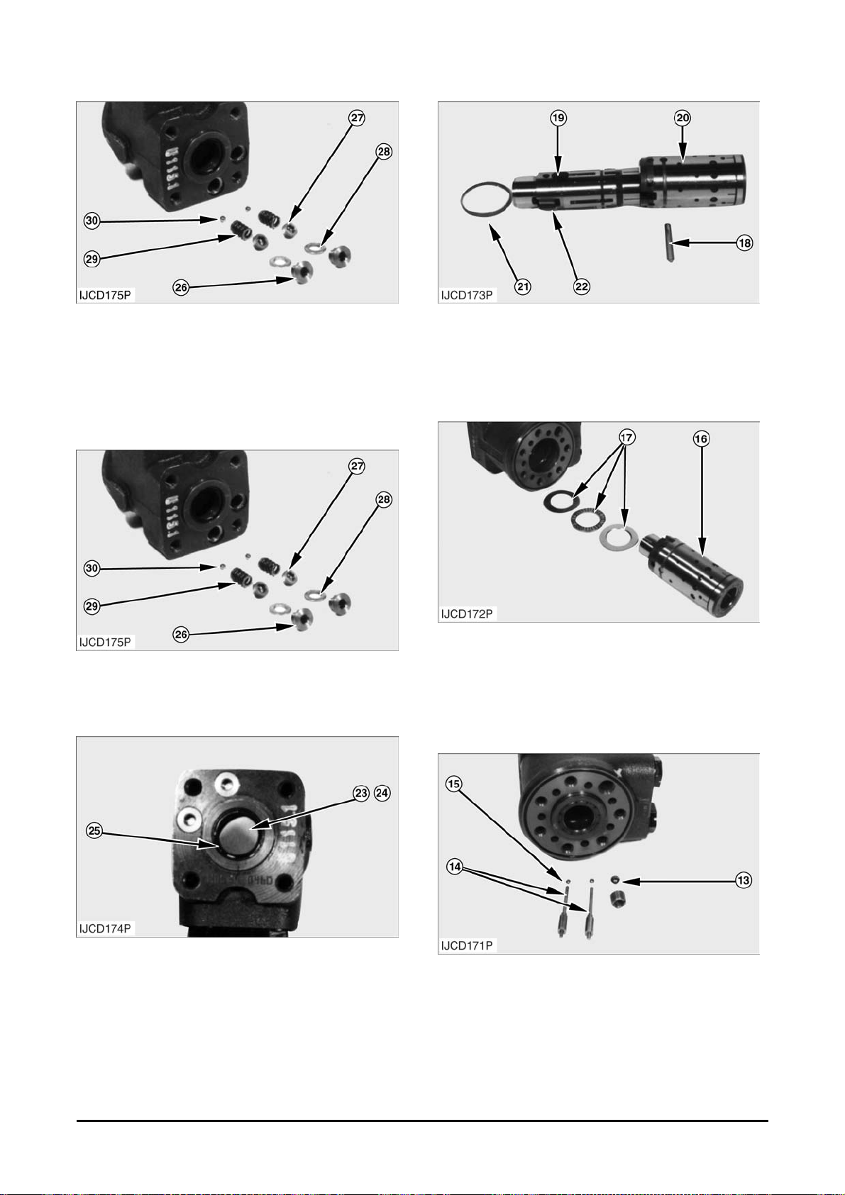
14. Remove plugs ( 26) , seats (27), seal-washers
(28), springs ( 29) and balls ( 30) from pump body
(2).
NOTE : The following steps ar e f or ass embling the
steering pump.
15. Ins tall balls (30), spring ( 29) , washer s ( 28) seats
(27) and plugs (26) into pum p body ( 2) . T i ghten
plugs to a torque of 50 ±10 N•m (37±7 lb•f t).
16. Ins tall lip seal (25). Install O-ring seal (23) with
king-ring (24) into pum p body ( 2) .
17. Ins tall springs (22) in spool (19) and ins tall ring
(21).
18. Position inner spool (19) in outer s pool ( 20) and
install pin (18).
NOTE : Use grease to hold bearing set (17) in
position on spool (16).
19. Inst all the bearing set (17) onto spool ass em bly
(16). Install spool ass embly (16).
20. Ins tall check valve ball (13).
21. Inst all s uc tion valve balls (15) and pins (14) in
the original positions int o the pump body.
Vehicle System Disassembly & Assembly 56
Page 59
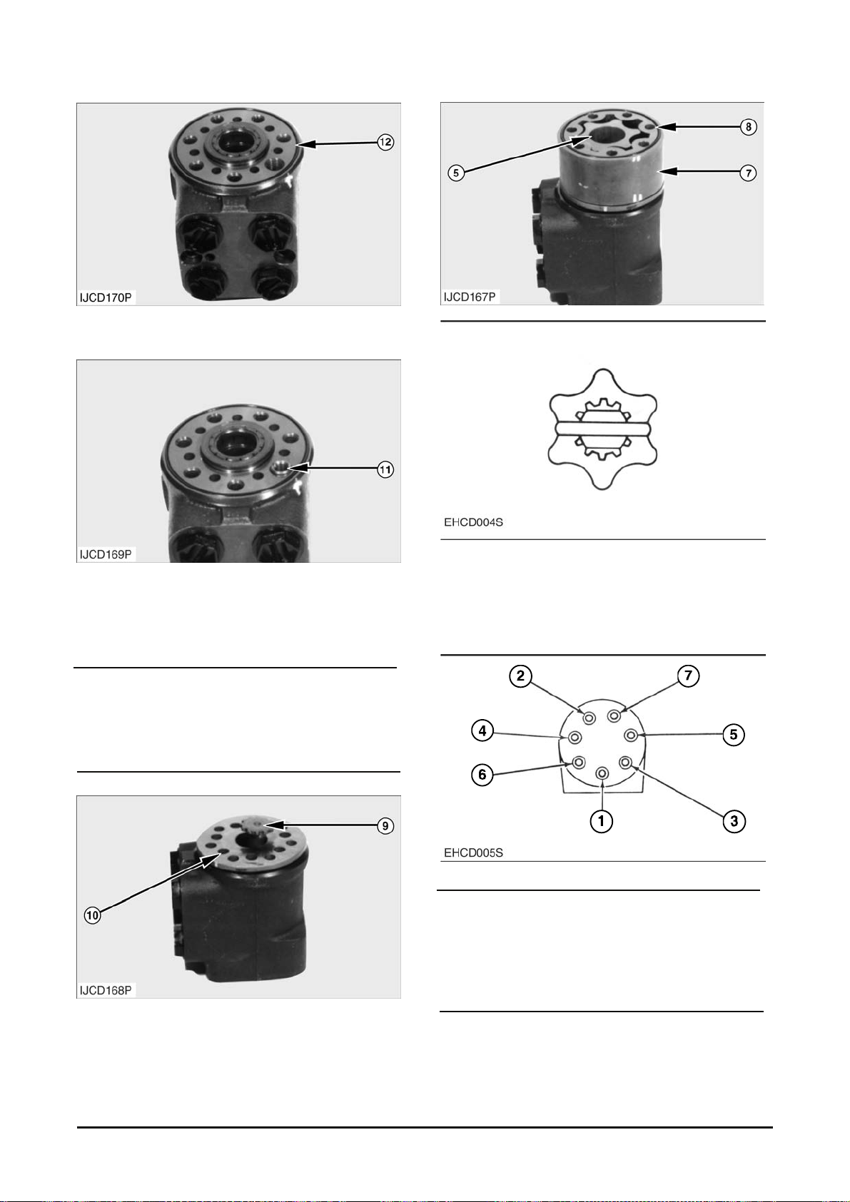
22. Ins tall O-ring seal (12) on the pump body.
23. Scr ew the threaded bush (11) lightly int o the
check valve bore. The t op of the bush must lie
just below the surf ac e of the housing.
NOTICE
Make sure the notch of shaft (9) properly seats on
pin (18) when installed into body (2) and spool (16).
24. Position gear upright and install s haft (9) and
distributor plat e (10), engaging the slot .
Typical Example
25. I nstall inner gear (5) and out er gear (7). Line up
the marks as indicated by arrow. Install O-ring
seal (8) onto the out er gear.
NOTICE
To assure proper oper ation of the pum p, make sure
bolts (2) are clean and dry before installing. Tighten
bolts (2) in the sequence shown in t he illustration.
Vehicle System Disassembly & Assembly 57
Page 60
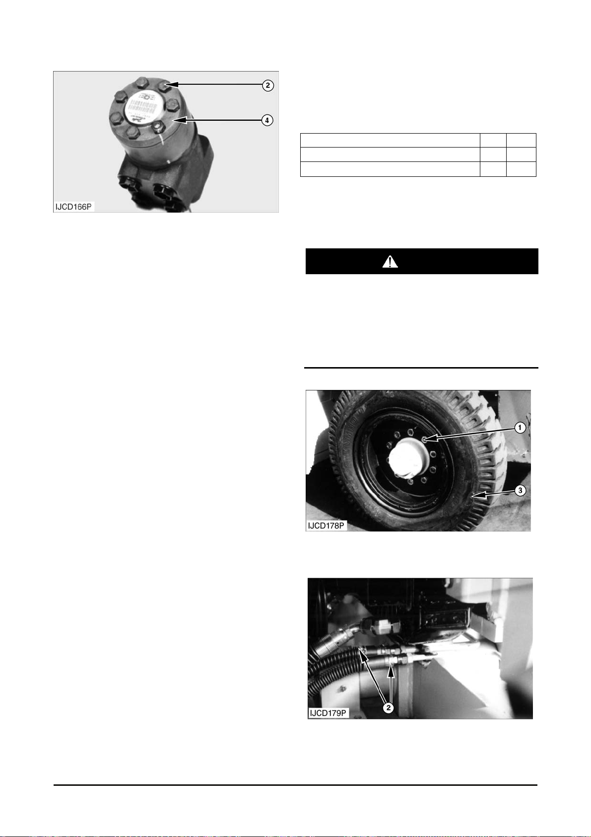
26. Inst all bolts (2) into cover (4). T ighten bolts (2) as
follows :
a. Tighten bolts (2) in c or r ect s equenc e to a first
torque of 15±6 N•m (132±50 lb•in).
b. Tighten bolts (2) in correct sequenc e to a
second torque of 30±6 N•m (264±50 lb•in).
27. Ins tall fitting over check valve (4) .
End By :
a. Install steering gear .
Steer Axle
Removal & Installation
Tools Needed A B
Jack Stand
Jack Stand
Start By :
a. Remove count er weight.
WARNING
To prevent personal injury, move the control
levers backward and forward to release any
pressure in hydraulic system. Slowl y loosen the
cap of the hydraulic tank to release any pressure
in the tank. Be ca utious of hot hydraulic oil when
any lines are disconnected in the hydraulic
system.
1. Loosen ten nuts (1) from steer tire wheel (3) (both
side).
2. Disconnect two power s teering hoses (2).
1
2
Vehicle System Disassembly & Assembly 58
Page 61
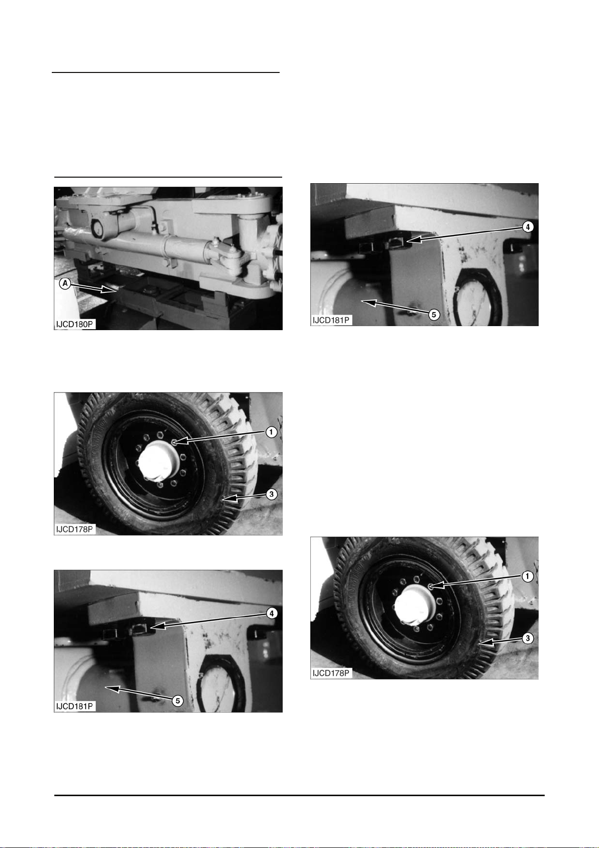
NOTICE
Place identification marks on all hydraulic
connectors and hoses to ass ure pr oper installation.
Plug and cap all hydraulic connect ors and hoses to
avoid debris and contamination from entering the
system.
3. Put tool (A) and floor jack in position under the
steer axle. Lift the frame off the steer axle. Put
tool (B) in position under both side of the frame.
4. Remove ten nuts (1) and steer tire (3).
5. Remove four rear mount ing bolts (4) and washers
from steer axle (5) .
6. Remove four front mounting bolts and washers
from the steer ax le.
7. Pull steer axle (5) clear of the fram e. Put blocks
under the axle to keep the axle stationary.
NOTE : The following steps ar e for installation of t he
steer axle.
8. Put the floor jack in position under t he steer ax le.
Remove the blocks. Move the axle into position
under the frame.
9. Lift the rear of the frame and remove tool (B) from
under the frame. Slowly lower the f rame on t o the
axle.
10. Put Loc tite No.242 on the threads of both of bolts
(4).
11. Ins tall the washers and bolts (4) at f r ont and rear
of the steer axle.
12. Tighten bolts (4) to a torque of 400~520 N•m
(295~380 lb•ft).
13. Inst all s teer tire (3) and nut (1).
Vehicle System Disassembly & Assembly 59
Page 62
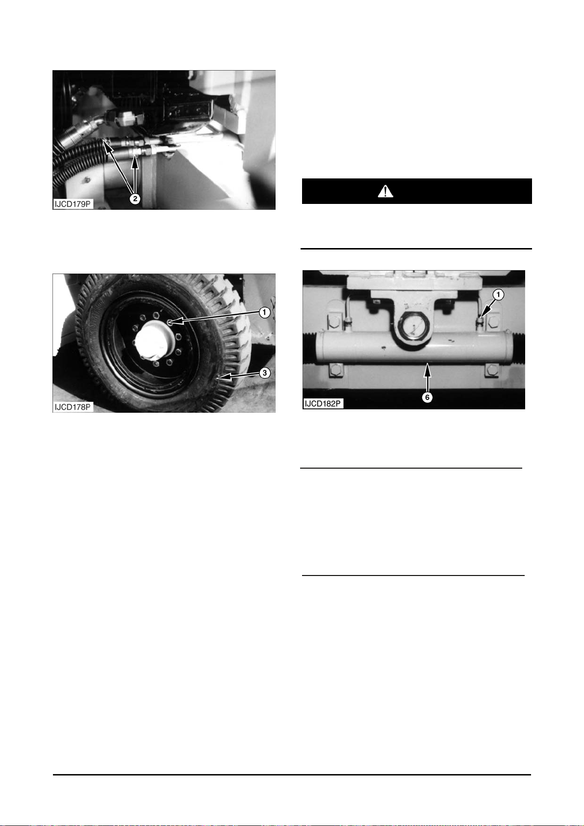
14. Lower and pull t he tool (A) from the steer axle.
15. Connect steering hoses (2) to tubes.
16. Tighten nuts (1) to a torque of 645 ± 35 N•m
(475 ± 25 lb•ft). Start the engine. Run the
steering cylinder t hr ough full stroke until all air is
removed from the hydr aulic s y stem . Add oil if
needed to the hydraulic t ank . Stop the engine.
See the Maintenance Manual.
End By :
a. Install counter weight.
Steering Cylinder
Removal & Installation
Start By :
a. Remove counte rweight.
WARNING
To prevent personal injury, move the control
levers backward and forward to release any
pressure in hydrau li c syst em.
1. Disconnect two steering tubes (1) from steering
cylinder (6).
NOTICE
Place identification marks on all hydraulic
connectors and hoses to ass ure pr oper installation.
Plug and cap all hydraulic connect ors and hoses to
avoid debris and contamination from entering the
system.
Vehicle System Disassembly & Assembly 60
Page 63
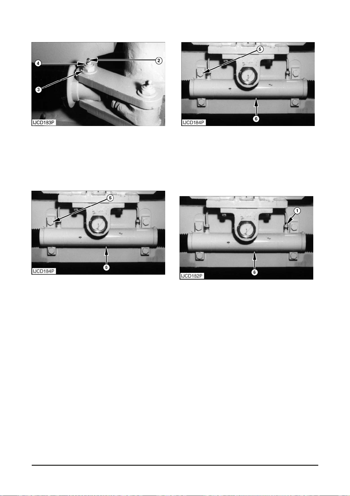
2. Remove grease nipple (2), locknut (3) and
washer from bolt s (4).
3. Install a 3/4"- 16 NF nut on bolt (4). Do not tighten
the nut. Hit the nut with a hammer to loosen the
bolt from the links. Remov e the nut. Remove the
bolt from the links.
4. Support steer ing c y linder (6) with hoist.
5. Remove bolts (5) and loc k was her s that hold
steering cylinder ( 6) in plac e.
6. Remove the steer ing c y linder.
NOTE : The following steps ar e for installation of t he
steering cylinder.
7. Fasten a hoist to steer ing c y linder (6) and put in
position to the steer ax le.
8. Install lockwas her s and bolts (5) that hold the
cylinder in place.
9. Tighten bolts (5) to a torque of 950±100 N•m
(700±75 lb•ft).
10. Connect tubes (1) to steering cylinder (6) . Turn
the wheels until hole of cy linder rod is aligned to
the hole of links.
Vehicle System Disassembly & Assembly 61
Page 64
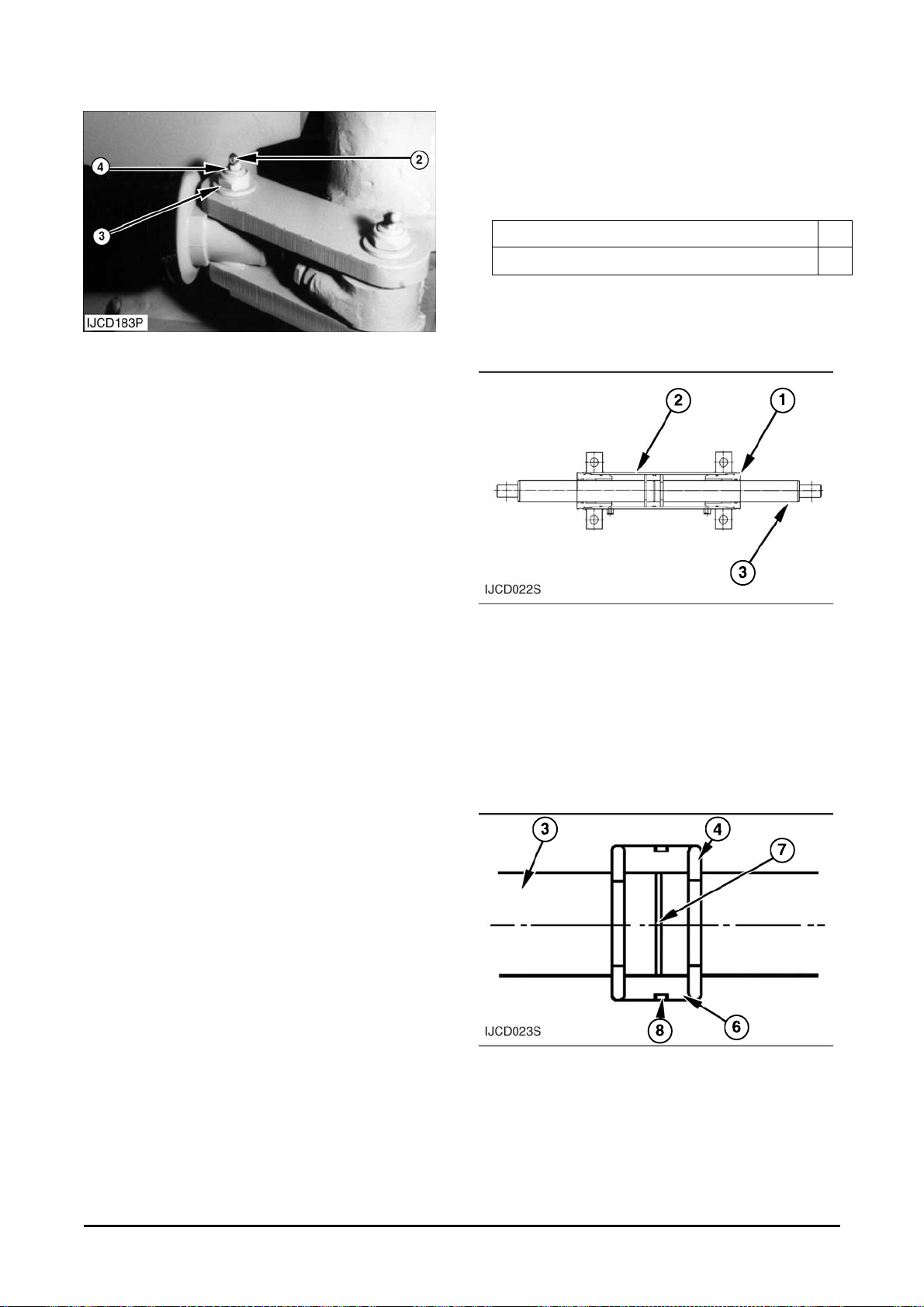
11. Inst all bolt (4) into links.
12. Ins tall washer, locknut (3) and gr eas e nipple ( 2)
on bolt (4).
13. Greased gr eas e in all gr eas e fittings. Start the
engine. Run steering cylinder (6) through full
stroke until all air is r em ov ed from the hy dr aulic
system.
Disassembly & Assembly
1. Start the engine. Tilt the mast forward as far as
possible. Stop t he engine.
Tools Needed A
Driver Group 1
Start By :
a. Remove steering cylinder.
1. Put the steering cy linder in position in a vise. Put
marks across each head and the tube for use at
assembly.
2. Loosen head (1) from tube (2) with rubber
hammer. Pull t he head out of tube and rem ov e it
from rod (3).
3. Remove rod and piston ( 3) from tube (2) .
4. Remove ring (4) from bot h side of piston (6) that
holds piston in position on rod ( 3).
5. Remove piston (6) from rod (3). Remove O-ring
seal (7) and back up-ring ( 8) from the pist on and
rod.
Vehicle System Disassembly & Assembly 62
Page 65
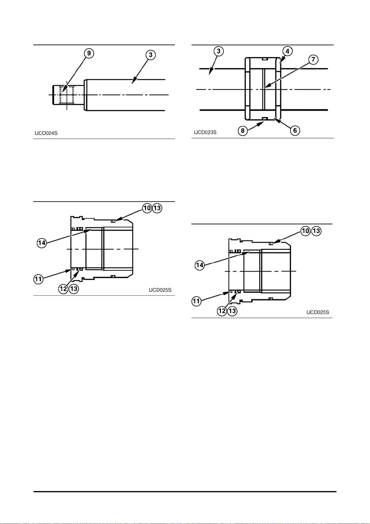
6. Inspect bushings (9) in the ends of rod (3). If a
replacement of the bushings is needed, remove
the bushings from the r od with tool (A).
7. Loosen the head in the opposite end of tube (2)
with a rubber hammer and r em ov e the head.
8. Remove O-ring s eal ( 10) from heads ( 1).
9. Remove wiper (11), U-pac king (12) and back up-
ring (13) from the bore of bot h head ( 1).
10. Ins pec t bushings (14) in the heads. If a
replacement of t he bushings are needed, replace
the bushings.
NOTE : The following steps are for the as sembly of
the steering cylinder .
11. If the bushings were removed fr om the rod (3),
install new bushings in the rod with tool (A).
12. Put clean hy dr aulic oil on s eal ( 5) and ins tall it on
piston (6) .
13. Put c lean hy dr aulic oil on bac k up- r ings ( 8) , O ring and install it on pist on (6). Install piston on
rod (3).
14. Ins tall rings (4) that hold pist on ( 6) in posit ion on
rod (3).
15. Put c lean hy dr aulic oil on bac k up- r ing ( 13) and
U-packing (12) and inst all it into head (1).
16. Put clean hy dr aulic oil on wiper ( 11) .
17. Inst all wiper ( 11) in both head. The lip of the
wiper must be installed away from the cylinder.
Vehicle System
Disassembly & Assembly 63
Page 66

NOTICE
Be careful during inst allation of heads ( 1) to prevent
damage to the O-ring seal on the head.
18. Put one of heads (1) in position on the cylinder
respective to the m ar k s put on the heads and
cylinder during disassem bly .
19.Carefully inst all the r od and piston in t he cylinder .
20. Carefully s lide the other head over rod (3) and
into cylinder (2) r es pec tive to the marks put on
the head and cylinder during disass embly.
End By :
a. Install st eer ing c y linder.
Steering Knuckle, Kingpin
And Bearings
Removal & Installation
Tools Needed A
Driver Group 1
Start By :
a. Remove wheel bearings ( s teer).
1. Rem ov e grease fitting ( 1), nut (2) and was her
from bolt (3).
2. Install a 3/4" - 16 NF nut (2) on the bolts ( 3). Do
not tighten the nut. Hit t he nut wit h a hammer to
loosen the bolt from the link s. Remove the nut.
Remove the bolt (3) fr om the link s .
3. Remove cover (4) and the gask et from both end
of the steering knuckl e.
Vehicle System Disassembly & Assembly 64
Page 67
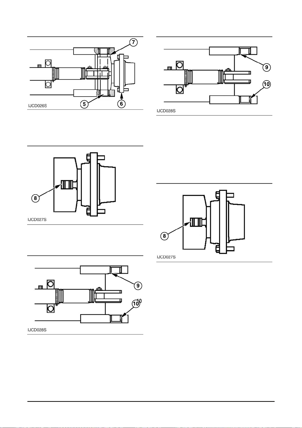
4. Remove kingpin (5).
5. Rem ov e k nuc k le (6) and thrust bearing (7) from
the axle beam.
6. Inspect the bushing (8) in t he k nuc k l e. If a
replacement of t he bus hing is needed, remove
the bushing from the knuck le with tool (A).
7. Remove the upper bearing ( 9) from the axle
beam with tool (A).
8. Remove the lower bearing ( 10) from the axle
beam with tool (A).
NOTE : The following steps ar e for installation of t he
steering knuckle, k ing pin, and bearings.
9. Install the lower bear ing (10) in the axle beam
with tool (A) until the bearing is 6.4 mm (.25 in)
below the surface t hat makes contact with the
steering knuckle.
10. Inst all upper bear ing ( 9) in the axle beam with
tool (A) until the bearing is 3.0 mm (.12 in) above
the surface that makes c ontact with the thrust
bearing.
11. If the bushing ( 8) was r em ov ed from the steering
knuckle, install new bus hing ( 8) in the knuckle
with tool (A).
Vehicle System Disassembly & Assembly 65
Page 68

13. Put knuc k le ( 6) and thr us t bearing ( 5) in pos ition
on the axle. Make sure the outer m etal shell of
the thrust bearing is next to the axle (away from
the knuckle).
14. Put t he kingpin (7) in pos ition in the axle and
knuckle.
15. Inst all the gaskets and cover (4) on the top and
bottom of the axle.
16. Pull t he link s into position. Install bolt (3) in the
links and knuckle.
17. Ins tall the washer nut (2) and grease fit ting (1)
on the bolt.
End By :
a. Install wheel bearings (steer).
b. Axle Stop Adjustment, as shown in Test ing A nd
Adjusting.
Vehicle System Disassembly & Assembly 66
Page 69
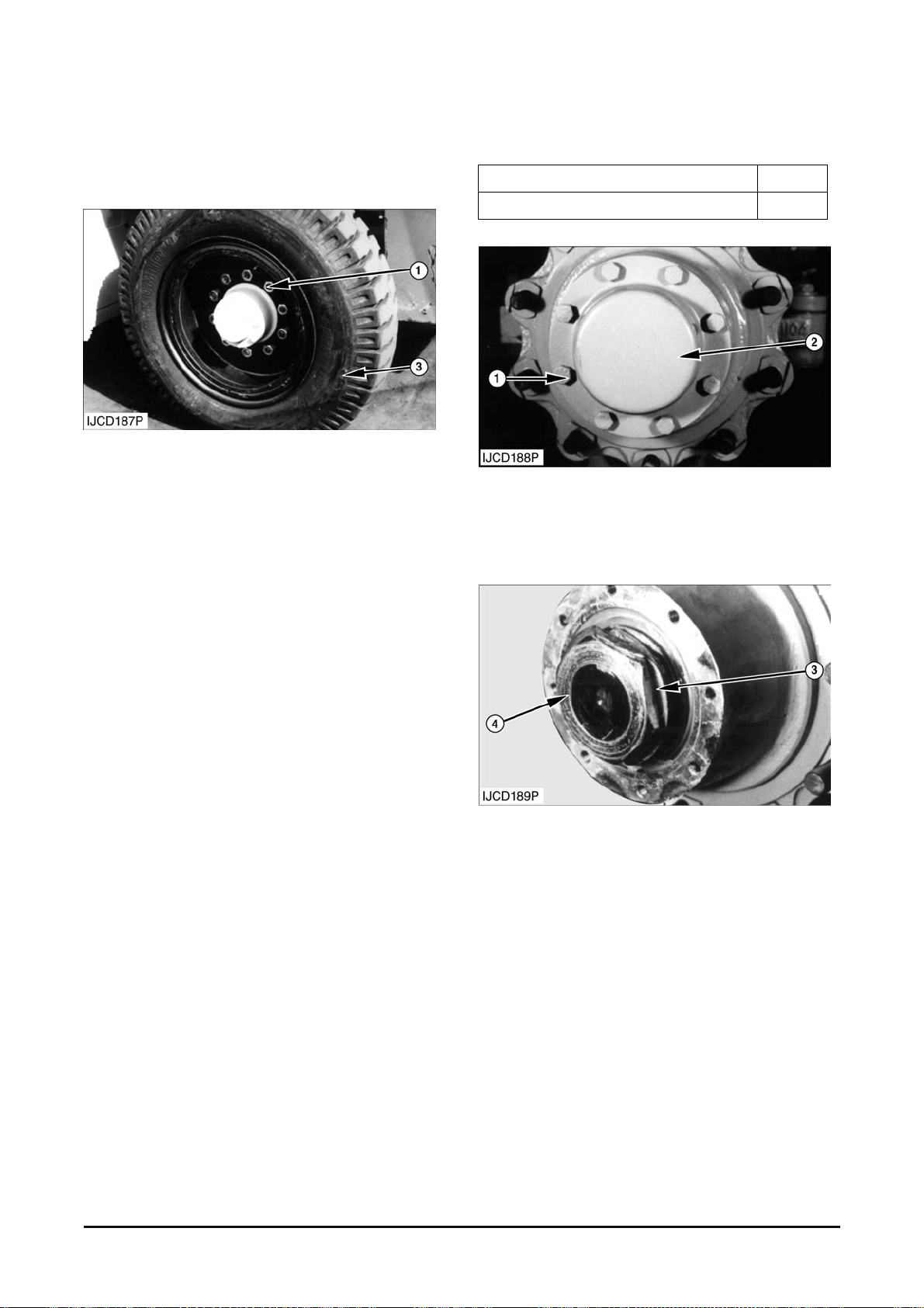
Steer Tire And Rim
Removal & Installation
1. Put a hydraulic jack in pos ition under the steer
axle.
2. Loosen nuts (1) t hat hold t he tire and rim in place.
3. Lift the steer ax le until the tire is clear of the
ground. Remove nuts (1). Remove the tire and
rim. The weight of the t ir e and r im is
approximately 75 kg ( 165 lb) .
NOTE : The following steps ar e for installation of the
tires and rims (st eer ) .
4. Put the tire and rim in pos ition on the hub.
5. Install nuts (1) that hold t he tire and rim in place.
Tighten the nuts t o a torque of 645 ± 35 N●m
(475 ± 25 lb●ft).
6. Lower the steer ax le and remove the hydraulic
jack.
Removal of Wheel Bearing
Tools Needed A
Driver Group 1
1. P ut a jack in position under the st eer axle. Lift the
truck until the st eer tire is clear of the ground.
2. Remove bolts (1) , cap ( 2) and the gask et f r om the
hub.
3. Bend the tine (t ab) on washer ( 3) out of the head
in outside nut (4).
Vehicle System Disassembly & Assembly 67
Page 70
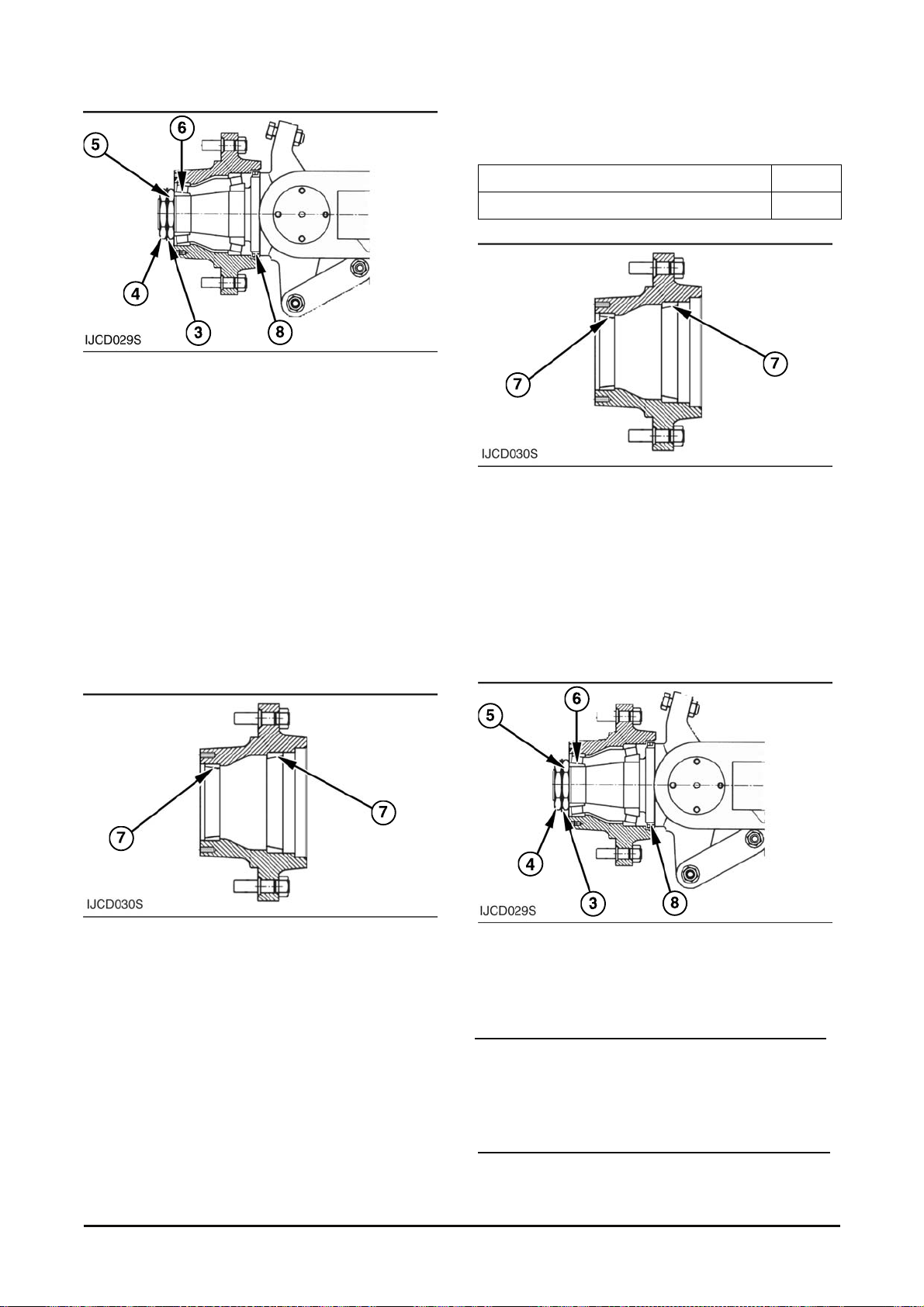
4. Rem ov e outside nut (4) wit h tool (A ).
5. Remove the tine (tab) on was her ( 3) out of t he
head in inside nut (5).
6. Remove washer (3) and ins ide nut (5) from the
steering knuckle.
7. Rem ov e the outer bearing cone (6) from the hub.
8. Put a power truck in position with the forks under
the steer tire. Remove the tire, wheel and hub
from the steering k nuc k le.
9. Rem ov e the seal (8) and inner bearing cup from
the hub.
10. Ins pec t bearing cups (7). If a replacement of the
bearing cups is needed, rem ov e the bearing
cups from the hub with a hammer and punc h.
Installation of Wheel Bearing
Tools Needed A
Wrench 1
1. If bearing cups (7) were rem ov ed from the hub,
lower the temperature of the cups and install the
cups in the hub.
2. P ut (pack) clean grease in inner bearing c one ( 7) .
Put the cone in position in the hub.
3. Install seal (8) in the hub wit h a rubber hammer.
The lip of the seal must be towar d the inside of
the hub. Put clean grease on t he lip of t he s eal.
4. P ut tire, wheel and hub in position on the forks of
a power truck. Put the tire, wheel and hub in
position on the steer ing k nuc k le.
NOTICE
Be extra caref ul during installation of t he wheel and
hub to prevent damage t o the seal.
Vehicle System Disassembly & Assembly 68
Page 71
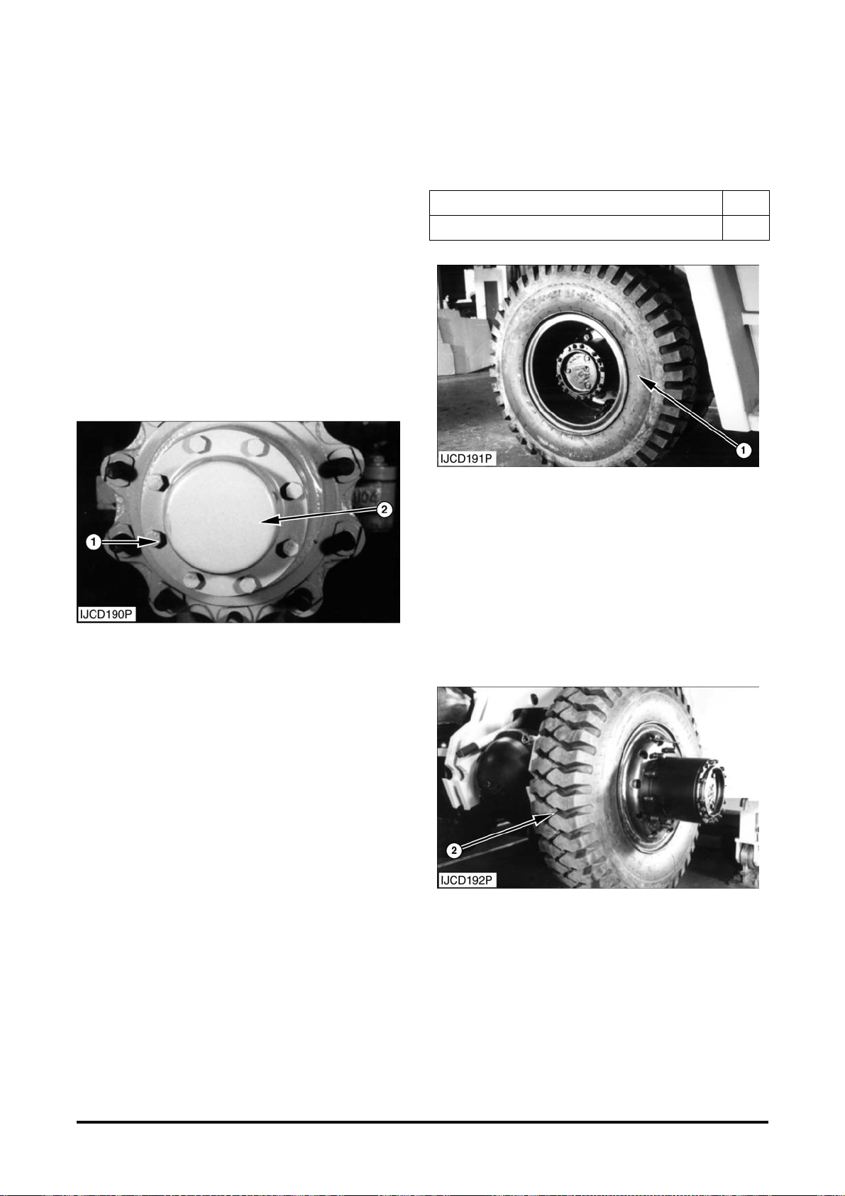
5. Put (pack) clean greas e in the outer bearing cone
(6). Install t he outer bearing cone (6) on the
steering knuckle.
6. Install washer (3) and ins ide nut (5) on the
steering knuckle
7. Tighten the nut to a torque of 590±60 N•m
(430±40 lb•ft) with tool (A) while the wheel is
turned. Loosen the nut. Tighten the nut again to a
torque of 295±30 N•m ( 215±20 lb•ft)
8. Install outs ide nut (4) on the steer axle knuckle.
tighten nut (4) to a torque of 590±60 N•m
(430±40 lb•ft) with tool (A).
9. B end the washers (3) in inside nut (5) and outside
nut (4).
10. Put t he gas k et and cap ( 2) in posit ion on the hub
and install the bolts ( 1) that hold the cap in place.
11. Lower the t ir e to the ground and remove the jack
from under the steer ax le.
Drive Tire And Rim
Removal & Installation
Tools Needed A
Socket 1
1. Lift the front of the truc k until the tires are clear of
the ground. Put a support in position under the
frame.
2. Remove the ten nuts t hat hold out er tire and rim
(1) in place with tool ( A ) and a tor que multiplier .
3. Put a power truck in position with the forks under
the outer tir e. Remov e the out er tire and r im. the
weight of the tire and rim is 68 kg (150 lb) .
4. Put a power truck in position with the forks under
the tire and remov e the inner tire and rim (2).
NOTE : The following steps ar e for ins tallation of the
tires and rims (drive) .
Vehicle System
Disassembly & Assembly 69
Page 72
5. Put the inner tire and r im ( 2) in posit ion on the
forks of a power truck. Put t he tire and rim in
position on the hub.
6. Put outer tire and r im (1) in position on the forks
of a power truck. Put the t ir e and r im in posit ion
on the hub.
7. Install the nuts that hold the outer tire and rim in
place. Tighten the nuts to a torque of 640~710
N∙m (475~525 lb∙ft). wit h tool (A ) and a t or que
multiplier.
8. Lift the front of the truc k and rem ov e the suppor t
from under the fram e. Lower the front of the truck.
Counterweight
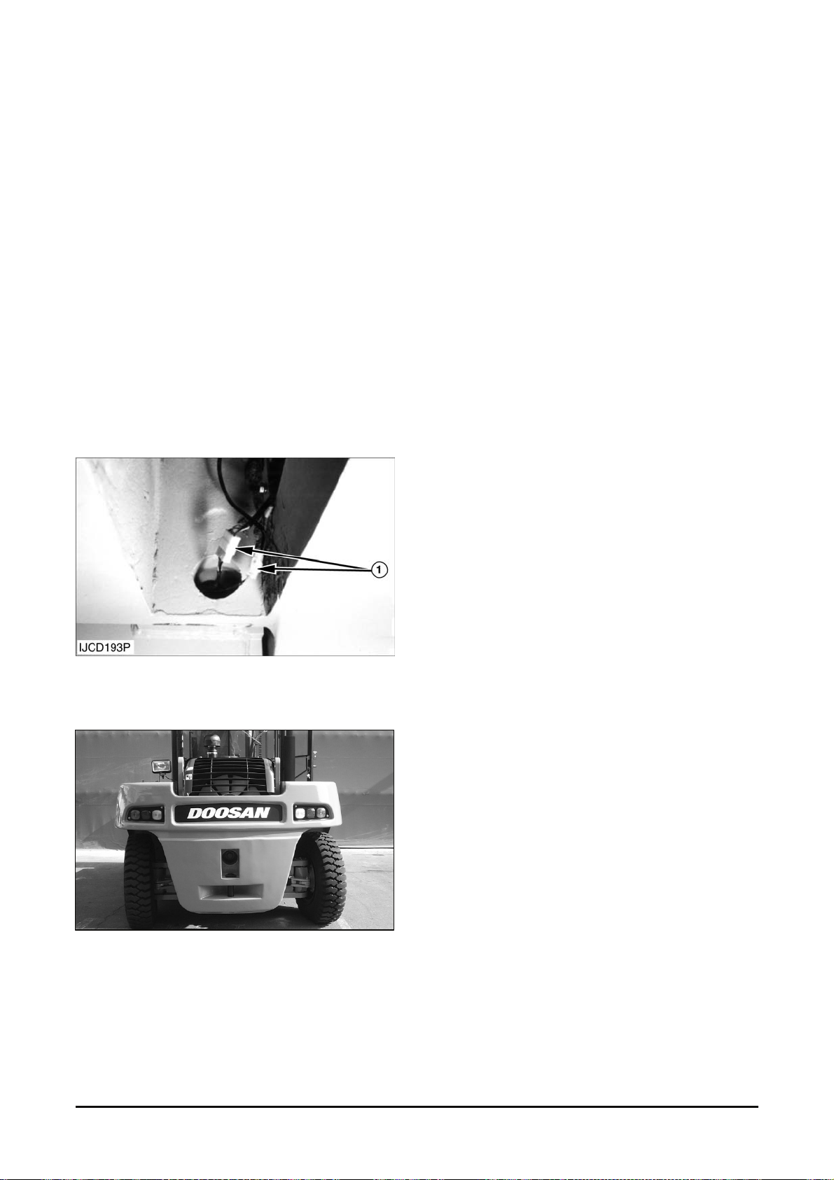
1. Disconnect wiring harnes s c onnec tors (1) for rear
lamp and combination lamp.
2. Fasten a hoist to the hook of t he c ounterweight.
3. Rem ov e bolts (2), and washers t hat hold t he
counterweight to the frame. Remove the
counterweight. The approximate weight of t he
counterweights are as follows:
D110S-5 ................................ 4,100 kg (9,038 lb)
D130S-5 .............................. 5,360 kg (11,816 lb)
D160S-5 .............................. 6,300 kg (13,890 lb)
NOTE : The following steps ar e for installation of t he
counterweight.
4. Fasten a hoist to hook of the counterweight and
put the counterweight in position on the frame.
5. Install washers and bolt ( 2) t hat hold t he
counterweight in place. Torque for a bolt (2) is
1030±100 N∙m (760± 75 lb∙ft).
Vehicle System Disassembly & Assembly 70
Page 73

Removal of Air
Pump – Motor line
If either main pum p or f an motor is replaced in the
field, be sure to apply the following bleeding
process:
1. Do not assemble the fan motor outlet hose A – at
this time.
2. A dd hy dr aulic oil in the tank. This will fill the
components and hoses displac ing any air until oil
begins to drain from the out let port.
3. A s s em ble the hose to the pump outlet.
4. Turn on the engine and keep it idle f or 3-5
minutes.
After chan gi n g mai n pump
Charging Valve
If either main pum p or f an motor is replaced in the
field, be sure to apply the following bleeding process.
1. Replace the main pump and add hydraulic oil in
the tank.
2. Open the gauge plug (PM) of char ging v alv e
3. Clos e the plug after 1 minute.
4. Turn on the engine and keep it idle f or 3 minute.
PM Port
Vehicle System
Disassembly & Assembly 71
Page 74

Air in Brake system
If you feel the brake pedal soft like a piece of
sponge, there is air in the brake hydraulic system.
The root cause can be low brake fluid level, brake
fluid leakage, damaged brake line or disconnected
brake line.
1. Chec k the hydraulic oil level and fill up if
necessary. See the O peration Manual.
2. Start up and run the engine in low idle state.
3. S tep on the brake pedal and open the bleed
screw (1) to r em ov e the air from the brake sy stem.
Retighten the bleed scr ew with the brake pedal
being pushed down. Release the brake pedal.
4. Repeat above operation until t he br ak e fluid is
free from air.
5. P er form the operations of abov e c laus es 3 and 4
with the bleed screw on t he right s ide.
Check the hydraulic oil level and r efill if necessary.
See the Operation Manual.
Removal of the High Pressure in
accumulator
Needle Valve
Charging Manifold
WARNING
In case that accumulator, brake valve, charging
manifold and the hydraulic hoses connected
between these parts are needed to check or
exchange, the pressure in the accumulator
should be released by using the needle valve
built in the charging manifold (see Figure 1). If
the pressure in the accumulator would not be
released, serious injury can happen.
To release the pressure in the accumulator, follow
these steps.
1. Turn off the engine
2. Open the cabin by using the cabin tilting function.
3. Turn the nut and screw of the needle valve built in
the charging manifold slowly to a counterclockwise
for two rota tions. Then the pres sure in the accumula tor
will be released slowly in 1 minute.
4. A fter releasing the pressure in the accumulator,
tighten the screw of this valve and nut to clockwise.
5. Clos e the cabin by using the cabin t ilting function.
Screw
Nut
Vehicle System Disassembly & Assembly
72
Page 75
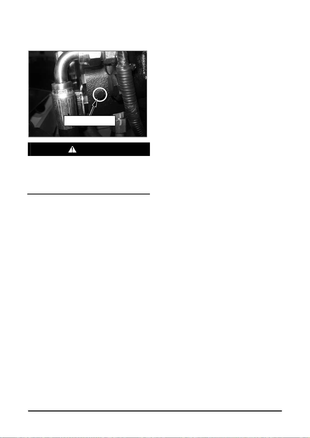
Emergency Lowering
If you cannot lower the carriage by pushing the
lift lever, you can lower it by using the
emergency descending control screw on the
main control valve. When lowering the carriage
by this method, it is very dangerous to stay
beneath or near the carriage.
Emergency control screw
for lowering the lif t
WARNING
Use the emergency desc ending control sc rew in the
following procedure;
1. S hut down the engine, and open the engine hood
beneath the seat.
2. Turn the emergency descending c ontrol screw on
the main control valv e by 2~ 3 turns
counterclockwise v ery slowly, and push the lift
lever to Descending direction. The carr iage will
descend slowly.
3. When the carriage has touched the ground,
tighten the scr ew surely. Therwise, no lift may
happen.
4. Clos e the engine hood.
Vehicle System
Disassembly & Assembly 73
Page 76
Removal and installation of
Engine and Transmission.
Stand by :
a) Remove the mast
Refer to the topic of Mast in this module for the
further information.
b) Remove the drive tire
c) Drain the transmis s ion oil
d) Drain the engine oil.
e) Drain the coolant.
f) Disassemble Driv e ax le.
1. Dismount the Overhead guard, hood, counter
weight and cabin.
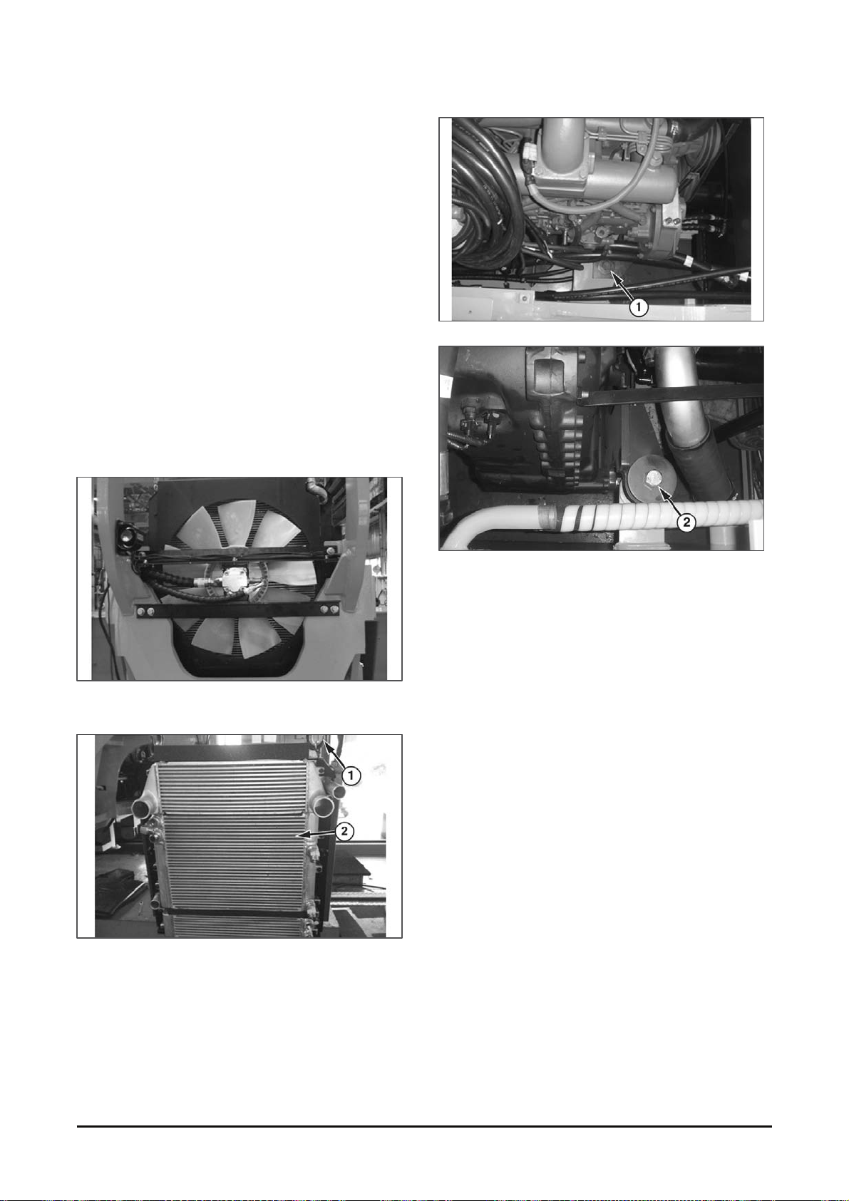
2. Dis m ount the radiator ( 2) using hoist with Eye-bolt
(1).
3. Dis as s em ble the Engine mounting bolt ( 1) and
Transmission m ounting bolt(2) after
disassembling the hoses, muffler flange and
harness and so on,
- ENGINE SIDE TORQUE(1) : MAX 279 N-m
- TRANSMISSION SIDE TORQUE(2) : 700 ± N-m
Vehicle System Disassembly & Assembly
74
Page 77
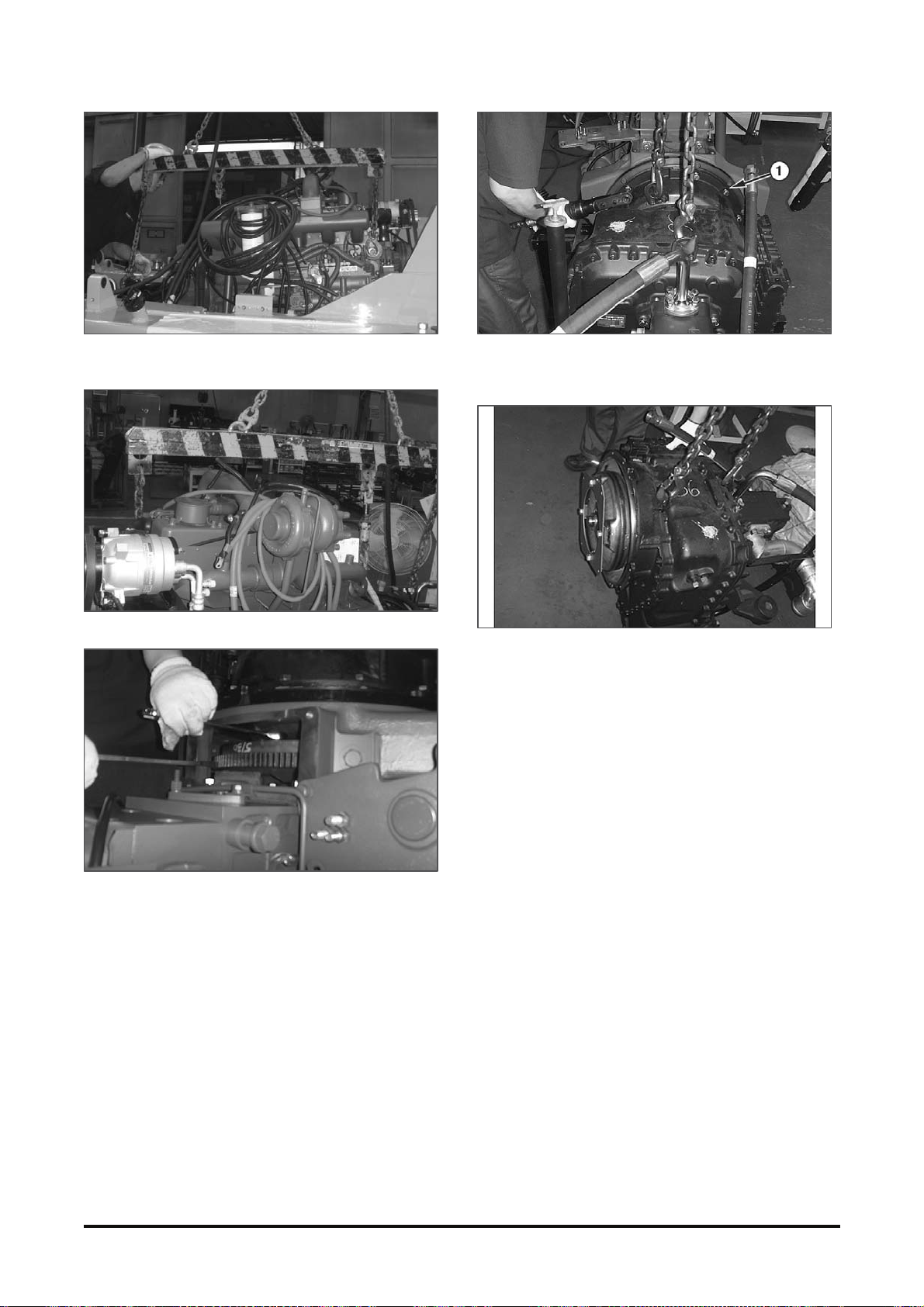
4. Fasten a hoist to hook position like the above
picture. (1500kg)
5. Dis m ount the Engine and transmission.
6. Rem ov e the bolt of flexible Plate.
7. Rem ov e the bolt and washer (1) aft er host ing the
transmission wit h Crane after disassembling t he
hoses. (1500kg)
8. Disassemble the transmission from Engine.
9. Install t he engine in the reverse order of removal
End by:
a) Install Cabin.
b) Install count weight.
c) Install mast.
Vehicle System
Disassembly & Assembly 75
Page 78

 Loading...