


EQ1030T47D-820
Light Commercial Truck
Service Manual
PEOPLE'S REPUBLIC OF CHINA
DONGFENG AUTOMOBIL CO.,LTD.
2006, 6
TOC
General
QD32 Engine
Clutch
Transmission
Front Suspension
Rear Axle & Rear Suspension
Propeller Shaft & Differential
Steering System
Brake System
Cab & Frame
Electric System
General
|
GL |
TOC |
|
Preventive Measures .................................................................................. |
GL-2 |
How to Use Manual ................................................................................... |
GL-3 |
Maintenance Specifications...................................................................... |
GL-4 |
Grease Application Place and Schedule ................................................ |
GL-7 |
Main Adjusting Data.................................................................................. |
GL-8 |
Lubricant ...................................................................................................... |
GL-8 |
Capacity Data .............................................................................................. |
GL-8 |
Fuel ................................................................................................................ |
GL-9 |
Engine Lubricant ........................................................................................ |
GL-9 |
Gear Oil ........................................................................................................ |
GL-9 |
Transmission Gear Oil............................................................................. |
GL-10 |
Lubricating Grease ................................................................................... |
GL-10 |
Fluid for Brake and Clutch..................................................................... |
GL-10 |
Engine Coolant.......................................................................................... |
GL-10 |
Tightening Torque .................................................................................... |
GL-10 |

General
General
This manual mainly contains maintenance and service method of the DONGFENG STAR EQ1030T47D-820 light commercial truck.
DONGFENG STAR |
Engine |
Equip |
|
|
|
EQ1030T47D-820 |
CYQD32 diesel |
COE, single row, with front independent suspension, |
|
engine |
power steering, front disc and rear drum brake |
|
|
|
To use vehicles safely and efficiently, it is important for you to read the manual thoroughly and make sure that you are familiar with the items that mark "Note".
Due to continuous improvements on our vehicles, maybe there are some instructions in the manual that does not compliance with the actual vehicles. Please consult the local agency for the latest news. The informaion in this manual are correct before issuance, DONGFENG reserve the rights of changing any of the content without notice.
Maintenance method varified due to different skill level, method, tools and available parts that serviceman adopts to. Any serviceman should firstly take into consideration on personal safety and vehicle safety when working.
The Application File Section of Test Department, the Commercial Product R & D Institute of DONGFENG AUTOMOBILE CO., LTD. is in charge of compiling.
2006,6
GL-1

General
Preventive Measures
See preventive measures below to get safe operation and suitable maintenance surely. These measures will not be repeated in the next pages.
1.Do not let engine run too long absolutely unless it is under special ventilation to ensure that there is good ventilation in working area, no fire things there.
Be careful sternly the any burnable, poisonous things like gasoline, refrigerant etc are used.
Working in a ditch or close environment and contacting any dangerous things, it is necessary any dangerous things,it is necessary to provide good ventilation in the working area, and smoking is prohibited there absolutely.
2.When truck is lifted, use a wheel stationary block to stop the truck move. After lifted, used a safe mat to support the truck on a specially designed point of truck to bear the truck weight, then begin its maintenance. These operations should be completed on an even ground.
3.Being unfixed a heavier assembly like engine, gear box or rear axle, be careful to keep it balance, avoid it fall down. And not permit to damage the details next to the brake pipes, etc.
4.Working at some maintenance without battery, turn off the ignition switch and power switch at first, and then take off the negative line on the battery to avoid unexpected accident happening like short circuit.
5.To prevent serious burnt accident, avoid touching some hot metal, such as radiator, exhaust manifold and muffler etc. When a engine is hot, do not take off the lid of radiator absolutely.
6.Before maintenance, use the suitable cloth to cover the inner ornaments and ground mat of the truck, in order to keep it in a good condition.
Note:
Be careful not smash the painted surface of the truck.
GL-2

General
7.Before the check and assembly of a disassembled part, clean it first.
8.During the reassembling, oil seal, gasket, O-washer, lock washer and split pin should use the new one.
9.Replace the outer and inner rings of tapered roller bearing in whole set.
10.Arrange the disassembling procedures according to the part assembling order.
11.Mark on the disassembled brake pipe about the connecting relationship.
12.Use suitable lubricating oil, brake fluid,cooling liquid and seal glue according to standard.
13.Use general and special tools to ensure maintenance safely and efficiently.
14.Deal properly with drained lubricating oil and solvent used to wash parts.
How to Use Manual
1.Look up contents as quickly as possible. The contents of every section are completely listed on the first page of each chapter.
2.The subject of each chapter is on the top of every page, showing the name of each system of assembly.
3.The page code of each chapter is of two or three letters, to show the name and page code of a certain chapter(ex, "BR-5").
4.A larger diagram is used to show the separated construction of an assembly, its contents: tightening torque, lubricating points, and the other information for maintenance. These are dor the reference of maintenance, and you have to see the SPARE PARTS CATALOG for parts booking.
5.The smaller diagram mainly indicate: every main checking procedures, all the tools needed, work skills latent procedures which are not listed in the larger diagram above. To some more complicated assembly system, in dictate them with diagrams one by one.
6.The measuring units in this book are mainly international standard ones.
7.The data and axplanation of maintenance are in the last pages of every chapter to be the reference.
8.In the procedure marked "Warning","Notes","Caution" strictly observe these procedure norms, to avoid body hurt and damage to some parts.
Warning: indicates if you do not follow this instruction, it will cause body hurts.
Note: indicates if you do not follow this instruction, it will cause some parts damaged.
Except some instructions of warning and notice, again some helpful information are provided.
GL-3

General
Maintenance Specifications
It is necessary for periodical inspection and maintenance of a vehicle to extend its service life, and improve on its power performance and fuel economy. So periodical inspection and maintenance should be carefully and maintenance should be carefully and strictly implemented in accordance with the following specifications so as to achiveve maximal economic and social benefits.
The users have to do the maintenance according to this chapter. The following schedule is only for maintenance items with in 4,0000km, it is also suitable for normal maintenance items after 40,000km.
—Running-in Maintenance Mileage 1,500~2,500km
—Running in maintenance items
—Normal maintenance items
Note:
Customers should carry out the inspection and maintenance intervals according to the different area condition. Properly shorten the maintenance intervals can ensure the truck to get the reasonable maintenance and move reliability. Never prolong the intervals.
CYDQ32 engine
R=Replace I=Inspect
Replace if necessary.
A=adjust C=Clean D=Dry and check
Maintenance Items |
|
|
|
|
|
Maintenance Intervals × 1000km |
|
|
|
|
|
|
|
|
|||||||||||||||
|
|
|
|
|
|
|
|
|
|
|
|
|
|
|
|
|
|
|
|
|
|
|
|
|
|
|
|
|
|
5 |
10 |
15 |
20 |
25 |
30 |
35 |
40 |
|
45 |
|
50 |
55 |
|
60 |
|
65 |
|
|
70 |
|
75 |
80 |
|||||||
|
|
|
|
|
|
|
|
||||||||||||||||||||||
|
|
|
|
|
|
|
|
|
|
|
|
|
|
|
|
|
|
|
|
|
|
|
|
|
|
|
|
|
|
Replace lubricant |
R |
R |
R |
|
R |
R |
R |
R |
R |
|
R |
|
R |
|
R |
|
R |
|
R |
|
|
R |
|
R |
R |
||||
Replace oil filter cartridge |
|
R |
|
|
R |
|
|
R |
|
R |
|
|
|
R |
|
|
|
R |
|
|
|
|
R |
|
|
|
R |
||
|
|
|
|
|
|
|
|
|
|
|
|
|
|
|
|
|
|
|
|
||||||||||
|
|
|
|
|
|
|
|
|
|
|
|
|
|
|
|
|
|
|
|
|
|
|
|
|
|
|
|
|
|
|
|
|
|
|
|
|
|
|
|
|
|
|
|
|
|
|
|
|
|
|
|
|
|
|
|
|
|||
|
|
|
|
|
|
|
|
|
|
|
|
|
|
|
|
|
|
|
|
||||||||||
Maintenance Items |
|
|
|
|
|
|
|
Maintenance Intervals × 1000km |
|
|
|
|
|
||||||||||||||||
|
|
|
|
|
|
|
|
|
|
|
|
|
|
|
|
|
|
|
|
|
|
|
|
|
|
|
|
||
|
|
|
1 |
|
|
10 |
20 |
|
|
30 |
40 |
|
|
50 |
|
|
60 |
|
|
70 |
|
|
80 |
||||||
|
|
|
|
|
|
|
|
|
|
|
|
|
|
|
|
|
|||||||||||||
|
|
|
|
|
|
|
|
|
|
|
|
|
|
|
|
|
|
|
|
|
|
|
|
|
|
|
|||
Exhaust device and tighting of other nuts |
|
I |
|
|
|
|
|
|
|
|
|
|
|
|
|
|
|
|
|
|
|
|
|
|
|
|
|||
Drive belt |
|
|
|
|
I |
|
|
|
I |
|
|
|
|
|
I |
|
|
|
|
|
|
I |
|
|
|
|
|
I |
|
Engine coolant |
|
|
|
|
|
|
|
|
|
|
|
|
|
|
R |
|
|
|
|
|
|
|
|
|
|
|
|
|
R |
Cooling system |
|
|
|
|
|
|
|
|
I |
|
|
|
|
|
I |
|
|
|
|
|
|
I |
|
|
|
|
|
I |
|
Fuel pipeline |
|
|
|
|
|
|
|
|
|
|
|
|
|
|
I |
|
|
|
|
|
|
|
|
|
|
|
|
|
I |
Air filter |
|
|
|
|
|
|
|
C |
C |
|
|
C |
|
R |
|
|
C |
|
|
C |
|
C |
|
|
R |
||||
Air inlet and outlet valve |
|
|
|
|
A |
|
|
|
A |
|
|
|
|
|
A |
|
|
|
|
|
|
A |
|
|
|
|
|
A |
|
Fuel spray nozzle |
|
|
|
|
|
|
|
|
|
|
|
|
|
1 |
|
|
|
|
|
|
|
|
|||||||
Idle speed |
|
|
|
|
I |
|
|
|
I |
|
|
|
|
|
I |
|
|
|
|
|
|
I |
|
|
|
|
|
I |
|
Note:
If the engine power apparently dropped, or exhausted black smoke, check the starting pressure of the fuel spray nozzle and fuel spray conditions, and adjust if necessary.
If there is a in the maintenance item, it has to follow the "Maintenance in bad using environment " and do the maintenance more frequent.
CYQD32 engine maintenance in bad using enviroment
The maintenance above is in the normal using environment, but if the vehicle is used in a bad environment for a long time, it will be necessary to do the following maintenance more frequent.
GL-4

General
A—Dusty area B—Frequent start in short time C—Towing long trailer D—Long tome idle speed E—Extremely bad climate, high temperature or bitter cold area.
|
Using Environment |
Maintenance Item |
Operation |
Maintenance Interval |
||||
|
|
|
|
|
|
|
|
|
A |
|
B |
C |
D |
|
Oil and oil filter |
Replace |
Often |
|
|
|
|
|
|
All types |
Replace |
Often |
A |
|
|
|
|
E |
Fuel filter |
Replace |
Every 20,000km |
Clutch
Maintenance Items |
|
Maintenance Intervals( × 1,000km |
|
|||||||||
|
|
|
|
|
|
|
|
|
|
|
||
|
4 |
8 |
12 |
16 |
20 |
24 |
28 |
32 |
36 |
40 |
||
|
||||||||||||
Check working condition of clutch |
|
|
|
|
|
|
|
|
|
|
|
|
Check clutch pedal free play |
|
|
|
|
|
|
|
|
|
|
|
|
|
|
|
|
|
|
|
|
|
|
|
|
|
Check hydraulic pipe line and pump for leakage |
|
|
|
|
|
|
|
|
|
|
|
|
Transmission
Maintenance Items |
|
Maintenance Intervals( × 1,000km |
|
|||||||||
|
4 |
8 |
12 |
16 |
20 |
24 |
28 |
32 |
36 |
40 |
||
|
||||||||||||
Check transmission for oil leakage |
|
|
|
|
|
|
|
|
|
|
|
|
|
|
|
|
|
|
|
|
|
|
|
|
|
Check transmission oil level |
|
|
|
|
|
|
|
|
|
|
|
|
|
|
|
|
|
|
|
|
|
|
|
|
|
Check worn condition between transmission and propeller shaft |
|
|
|
|
|
|
|
|
|
|
|
|
spline |
|
|
|
|
|
|
|
|
|
|
|
|
Check the connections of control mechanism for looseness |
|
|
|
|
|
|
|
|
|
|
|
|
|
|
|
|
|
|
|
|
|
|
|
|
|
Replace transmission lubricant oil |
|
|
|
|
|
|
|
|
|
|
|
|
|
|
|
|
|
|
|
|
|
|
|
|
|
Brake system
Maintenance Items |
|
Maintenance Intervals( × 1,000km |
|
|||||||||
|
|
|
|
|
|
|
|
|
|
|
||
|
4 |
8 |
12 |
16 |
20 |
24 |
28 |
32 |
36 |
40 |
||
|
||||||||||||
Check effectiveness of service brake and parking brake |
|
|
|
|
|
|
|
|
|
|
|
|
Check brake line for oil leakage |
|
|
|
|
|
|
|
|
|
|
|
|
|
|
|
|
|
|
|
|
|
|
|
|
|
Check remain hydraulic oil of clutch and brake system |
|
|
|
|
|
|
|
|
|
|
|
|
|
|
|
|
|
|
|
|
|
|
|
|
|
Check the tightness of the brake support plate |
|
|
|
|
|
|
|
|
|
|
|
|
|
|
|
|
|
|
|
|
|
|
|
|
|
Check brake pedal free play |
|
|
|
|
|
|
|
|
|
|
|
|
|
|
|
|
|
|
|
|
|
|
|
|
|
Check brake shoe for wearing |
|
|
|
|
|
|
|
|
|
|
|
|
|
|
|
|
|
|
|
|
|
|
|
|
|
Check vacuum booster oil pipe and valve for oil leakage |
|
|
|
|
|
|
|
|
|
|
|
|
|
|
|
|
|
|
|
|
|
|
|
|
|
Check brake drum and brake disc for wearing |
|
|
|
|
|
|
|
|
|
|
|
|
|
|
|
|
|
|
|
|
|
|
|
|
|
Replace hydraulic oil of clutch and brake system |
|
|
|
|
|
|
|
|
|
|
|
|
|
|
|
|
|
|
|
|
|
|
|
|
|
Check parking brake lever and steel wire for the working condition |
|
|
|
|
|
|
|
|
|
|
|
|
Steering system
Maintenance Items |
|
Maintenance Intervals( × 1,000km |
|
|||||||||
|
4 |
8 |
12 |
16 |
20 |
24 |
28 |
32 |
36 |
40 |
||
|
||||||||||||
Check steering gear and pipe for oil leakage |
|
|
|
|
|
|
|
|
|
|
|
|
|
|
|
|
|
|
|
|
|
|
|
|
|
Check the tightening condition of pitman arm |
|
|
|
|
|
|
|
|
|
|
|
|
|
|
|
|
|
|
|
|
|
|
|
|
|
Check the tightening condition of steering gear to thr frame |
|
|
|
|
|
|
|
|
|
|
|
|
|
|
|
|
|
|
|
|
|
|
|
|
|
GL-5

General
Steering system
Maintenance Items |
|
Maintenance Intervals( × 1,000km |
|
|||||||||
|
|
|
|
|
|
|
|
|
|
|
||
|
4 |
8 |
12 |
16 |
20 |
24 |
28 |
32 |
36 |
40 |
||
|
||||||||||||
Check the tightening condition of tie rod ends and drag link joints |
|
|
|
|
|
|
|
|
|
|
|
|
|
|
|
|
|
|
|
|
|
|
|
|
|
Check the tightening condition of transition arm and driven arm |
|
|
|
|
|
|
|
|
|
|
|
|
|
|
|
|
|
|
|
|
|
|
|
|
|
Check steering gearing device for looseness |
|
|
|
|
|
|
|
|
|
|
|
|
|
|
|
|
|
|
|
|
|
|
|
|
|
Check steering wheel for free play and operating |
|
|
|
|
|
|
|
|
|
|
|
|
|
|
|
|
|
|
|
|
|
|
|
|
|
Check steering gear oil level,add if necessary |
|
|
|
|
|
|
|
|
|
|
|
|
|
|
|
|
|
|
|
|
|
|
|
|
|
Check spline hub of the steering drive shaft for wear |
|
|
|
|
|
|
|
|
|
|
|
|
|
|
|
|
|
|
|
|
|
|
|
|
|
Check and adjust front wheel toe-in |
|
|
|
|
|
|
|
|
|
|
|
|
|
|
|
|
|
|
|
|
|
|
|
|
|
Check the tightening condition of upper and lower cross arm ball head |
|
|
|
|
|
|
|
|
|
|
|
|
to steering knuckle |
|
|
|
|
|
|
|
|
|
|
|
|
Clean steering gear and pipe, replace steering gear oil |
|
|
|
|
|
|
|
|
|
|
|
|
|
|
|
|
|
|
|
|
|
|
|
|
|
Check front wheel alignment |
|
|
|
|
|
|
|
|
|
|
|
|
|
|
|
|
|
|
|
|
|
|
|
|
|
Check the pull rod ball head working condition of the steering system |
|
|
|
|
|
|
|
|
|
|
|
|
Suspension system
Maintenance Items |
|
Maintenance Intervals( × 1,000km |
|
|||||||||
|
4 |
8 |
12 |
16 |
20 |
24 |
28 |
32 |
36 |
40 |
||
|
||||||||||||
Check shock absorber for oil leakage and fasten bracket bolts |
|
|
|
|
|
|
|
|
|
|
|
|
|
|
|
|
|
|
|
|
|
|
|
|
|
Clean rear leaf spring and shock absorber |
|
|
|
|
|
|
|
|
|
|
|
|
|
|
|
|
|
|
|
|
|
|
|
|
|
Check the working condition of the front independent suspension |
|
|
|
|
|
|
|
|
|
|
|
|
upper and lower cross arm ball pin and the dust cap |
|
|
|
|
|
|
|
|
|
|
|
|
Check the working condition of torsion bar fixed adjusting arm |
|
|
|
|
|
|
|
|
|
|
|
|
|
|
|
|
|
|
|
|
|
|
|
|
|
Tighten U-bolts and nuts of leaf spring during full load |
|
|
|
|
|
|
|
|
|
|
|
|
|
|
|
|
|
|
|
|
|
|
|
|
|
Check the working condition of front suspension torsion bar and push |
|
|
|
|
|
|
|
|
|
|
|
|
rod |
|
|
|
|
|
|
|
|
|
|
|
|
Check the working condition of front independent suspendion upper |
|
|
|
|
|
|
|
|
|
|
|
|
and lower cross arm |
|
|
|
|
|
|
|
|
|
|
|
|
Tighten the connecting bolt of front independent suspension |
|
|
|
|
|
|
|
|
|
|
|
|
|
|
|
|
|
|
|
|
|
|
|
|
|
Check the tightening condition of leaf spring shackle bolt |
|
|
|
|
|
|
|
|
|
|
|
|
|
|
|
|
|
|
|
|
|
|
|
|
|
Check the working condition of rubber assist spring |
|
|
|
|
|
|
|
|
|
|
|
|
|
|
|
|
|
|
|
|
|
|
|
|
|
Check leaf spring and shock absorber for any damage |
|
|
|
|
|
|
|
|
|
|
|
|
|
|
|
|
|
|
|
|
|
|
|
|
|
Replace leaf spring pins and sleeves |
|
|
|
|
|
|
|
|
|
|
|
|
|
|
|
|
|
|
|
|
|
|
|
|
|
Check the working condition of front independent suspendion rubber |
|
|
|
|
|
|
|
|
|
|
|
|
limit block |
|
|
|
|
|
|
|
|
|
|||
|
|
|
|
|
|
|
|
|
|
|
||
|
|
|
|
|
|
|
|
|
|
|
|
|
Check the vehicle left and right height |
|
|
|
|
|
|
|
|
|
|
|
|
|
|
|
|
|
|
|
|
|
|
|
|
|
If the ball pin dust cap is damaged, replace it immediately, because it may damage the ball pin and cause danger in driving.
Propeller shaft
Maintenance Items |
|
Maintenance Intervals( × 1,000km |
|
|||||||||
|
4 |
8 |
12 |
16 |
20 |
24 |
28 |
32 |
36 |
40 |
||
|
||||||||||||
Check shaft connecting part for looseness |
|
|
|
|
|
|
|
|
|
|
|
|
|
|
|
|
|
|
|
|
|
|
|
|
|
Check tightening condition of spider bearing of propeller shaft |
|
|
|
|
|
|
|
|
|
|
|
|
|
|
|
|
|
|
|
|
|
|
|
|
|
Check propeller shaft splines for wear and damage |
|
|
|
|
|
|
|
|
|
|
|
|
GL-6

General
Axle & wheel
Maintenance Items |
|
Maintenance Intervals( × 1,000km |
|
|||||||||
|
4 |
8 |
12 |
16 |
20 |
24 |
28 |
32 |
36 |
40 |
||
|
||||||||||||
Clean front, rear axle assembly and wheel assembly |
|
|
|
|
|
|
|
|
|
|
|
|
|
|
|
|
|
|
|
|
|
|
|
|
|
Check main reductor for oil leakage |
|
|
|
|
|
|
|
|
|
|
|
|
|
|
|
|
|
|
|
|
|
|
|
|
|
Check tire pressure and wheel bolt and nut for tightening torque |
|
|
|
|
|
|
|
|
|
|
|
|
|
|
|
|
|
|
|
|
|
|
|
|
|
Check tire for wear and damage |
|
|
|
|
|
|
|
|
|
|
|
|
|
|
|
|
|
|
|
|
|
|
|
|
|
Check lubricant level of main reductor and clean the vent plug |
|
|
|
|
|
|
|
|
|
|
|
|
|
|
|
|
|
|
|
|
|
|
|
|
|
Rotate tires |
|
|
|
|
|
|
|
|
|
|
|
|
|
|
|
|
|
|
|
|
|
|
|
|
|
Replace the main reductor lubricant |
|
|
|
|
|
|
|
|
|
|
|
|
Other
Maintenance Items |
|
Maintenance Intervals( × 1,000km |
|
|||||||||
|
4 |
8 |
12 |
16 |
20 |
24 |
28 |
32 |
36 |
40 |
||
|
||||||||||||
Check the connecting part tightening conditions of cargobody to |
|
|
|
|
|
|
|
|
|
|
|
|
frame |
|
|
|
|
|
|
|
|
|
|
|
|
Check thelongitudinal and cross member of the cargo body for loose- |
|
|
|
|
|
|
|
|
|
|
|
|
ness and damage |
|
|
|
|
|
|
|
|
|
|
|
|
Check chassis frame rivets for looseness |
|
|
|
|
|
|
|
|
|
|
|
|
|
|
|
|
|
|
|
|
|
|
|
|
|
Check connections of cab for looseness |
|
|
|
|
|
|
|
|
|
|
|
|
|
|
|
|
|
|
|
|
|
|
|
|
|
Check battery electrolyte level (fill up if it is not enough) |
|
|
|
|
|
|
|
|
|
|
|
|
Periodic Replacement
Periodical replacement parts are hose which deteriorate with lapse of time. These parts are mainly rubber parts such as brake hoses,fuel hoses. It is difficult to predict the safety of these parts when checking them with the method used in the usual predict inspection. Hence, applicable parts must be replaced whether they appear to be usable or not.
Replace Items |
|
|
|
Replace Intervals (Year) |
|
|
|
||||||
1 |
2 |
3 |
4 |
5 |
6 |
7 |
8 |
9 |
10 |
11 |
12 |
||
|
|||||||||||||
Rubber parts of brake valves |
|
|
|
|
|
|
|
|
|
|
|
|
|
|
|
|
|
|
|
|
|
|
|
|
|
|
|
Rubber hoses of brake system |
|
|
|
|
|
|
|
|
|
|
|
|
|
|
|
|
|
|
|
|
|
|
|
|
|
|
|
Rubber hoses for vacuum pump |
|
|
|
|
|
|
|
|
|
|
|
|
|
|
|
|
|
|
|
|
|
|
|
|
|
|
|
Rubber hoses of clutch control system |
|
|
|
|
|
|
|
|
|
|
|
|
|
|
|
|
|
|
|
|
|
|
|
|
|
|
|
Rubber sealing ring of master and slave cylinder of clutch |
|
|
|
|
|
|
|
|
|
|
|
|
|
|
|
|
|
|
|
|
|
|
|
|
|
|
|
Front independent suspension upper and lower cross arm ball pin |
|
|
|
|
|
|
|
|
|
|
|
|
|
assembly |
|
|
|
|
|
|
|
|
|
|
|
|
|
Propeller shaft spider assembly |
|
|
|
|
|
|
|
|
|
|
|
|
|
|
|
|
|
|
|
|
|
|
|
|
|
|
|
Steering drive shaft spider ball pin assembly |
|
|
|
|
|
|
|
|
|
|
|
|
|
|
|
|
|
|
|
|
|
|
|
|
|
|
|
Grease Application Place and Schedule
Greasing should be performed periodically for all parts of the vehicle. Before filling up, clean all dust and dirty from the grease nipples and other parts which are needed to lubricated, then apply grease. After greasing, wipe off the excess grease. Be sure to put the caps back on.The table includes first 40,000km lubricating schedule. You have to follow the schedule after the first several kilometers.
—Running-in maintenance mileage (1,500~2,500km)
GL-7
General
—Running-in maintenance lubrication item
—Normal driving lubricating item
Place of lubricating |
Lubricating interval mileage × 1,000km |
|||||||||||
|
|
|
|
|
|
|
|
|
|
|
||
|
4 |
8 |
12 |
16 |
20 |
24 |
28 |
32 |
36 |
40 |
||
|
||||||||||||
Slip yoke of steering drive shaft and spider bearing |
|
|
|
|
|
|
|
|
|
|
|
|
Door hinge |
|
|
|
|
|
|
|
|
|
|
|
|
|
|
|
|
|
|
|
|
|
|
|
|
|
Door lock, glass regulator, odometer flexible shaft |
|
|
|
|
|
|
|
|
|
|
|
|
|
|
|
|
|
|
|
|
|
|
|
|
|
Hub bearing |
|
|
|
|
|
|
|
|
|
|
|
|
Main Adjusting Data
|
Adjusting Items |
Standard |
|
Air valve clearance (cold) |
|
Inlet valve |
0.35mm |
|
Exhaust valve |
0.35mm |
|
|
|
||
Oil pressure of idling engine |
|
|
69~100kPa |
Oil pressure of normal run engine |
196~490kPa |
||
Water temperature of normal run engine |
80~95 |
||
Tension grade of alternator belt |
|
|
10~15mm |
Free travel of clutch pedal |
|
|
25~40mm |
Free play of brake pedal |
|
|
20~25mm |
Steering wheel free play |
|
|
10° |
Toe-in |
|
|
0~2mm |
Lubricant
Place |
Lubricant |
|
Type |
Grade |
|
Engine lubricating system |
Engine oil |
|
5W/20 |
API CF-4 |
|
Engine cooling system |
Antifreeze, anti-rust coolant |
|
|
|
|
Transmission |
Manual operation special oil |
|
75W/90 |
API GL-4 |
|
Main reductor |
Industrial gear oil |
|
75W/90 |
API GL-5 |
|
Steering gear |
Power steering fluid |
|
ATF-2 |
|
|
Clutch & brake system |
Synthetic brake liquid |
|
901-4 |
DOT4 |
|
Bearing and ball pin |
Li-base lubricant grease |
|
2, 3# |
SH0535-93 |
|
Capacity Data |
|
|
|
|
|
|
|
|
|
|
|
Part |
|
|
|
Capacity (L) |
|
|
|
|
|
|
|
Fuel tank |
|
|
65 |
|
|
Engine lubricant system |
|
|
6.5 |
|
|
Water tank and cooling system |
|
|
|
13 to full |
|
Transmission |
|
|
2.7 |
|
|
Main reductor |
|
|
6.5~5.0 to overflow |
|
|
Steering gear |
|
|
|
to the MAX |
|
Brake system |
|
|
|
to the MAX |
|
GL-8
General
Fuel
The qualified light diesel oil specified by GB/T19147-2003 could be applied for in China, and the users choose different qualified light diesel oil according to the local temperature.
0# Light diesel oil |
Local temperature above |
4 |
|
10# Light diesel oil |
Local temperature above |
-5 |
|
20# Light diesel oil |
Local temperature between |
-5 ~ -14 |
|
35# Light diesel oil |
Local temperature between |
-14 ~ -29 |
|
50# Light diesel oil |
Local temperature between |
-29 ~ -44 |
|
|
|
|
|
As for the vehicle for export, please take the local national regulations and standards and the climate for reference to choose the proper diesel oil.
Engine Lubricant
API CF-4 Grade diesel oil or special oil for CYQD32 is recommended. According to the local air temperature, the user may choose different CF oil with different viscosity grade. Recommended temperature range is as below.
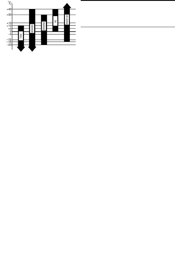
Gear Oil
Middle-load (API GL-4) gear oil, heavy-load (GL-5) gear oil is recommended. The recommended ambient temperature range for all gear oil is as below:
GL-9

General
Transmission Gear Oil
The manually operated gear oil API GL-4, 75W/90 is recommended.
Lubricating Grease
The compound lithium grease is recommended, but the general lithium grease could also be used.
Fluid for Brake and Clutch
The DOT4, 901-4 brake fluid is recommended.
Note:
Never use brake fluid with different quality or type.
Engine Coolant
Long effective frostbite antirust fluid is recommended and its freezing point must be lower than the lowest local temperature for 8 .
Tightening Torque
Tightening torque of the important part
Part |
Tightening torque (N.m) |
|
|
|
|
Upper cross arm and ball connecting part |
22~26 |
|
|
|
|
Ball joint and steering shaft connecting part |
78~98 |
|
|
|
|
Buffer rubber and cross member connecting part |
62~76 |
|
|
|
|
Distance rod front end locking nut |
118~157 |
|
|
|
|
Distance rod and cross member connecting part |
54~71 |
|
|
|
|
Lower cross arm fixed nut |
108~147 |
|
|
|
|
Upper cross arm fixed part on the frame |
108~147 |
|
|
|
|
Torsion arm and lower cross arm fixed part |
50~68 |
|
|
|
|
Upper cross arm fixed nut of two ends |
71~103 |
|
|
|
|
Adjusting nut (on the adjusting arm) |
108~127 |
|
|
|
|
Lower cross arm cotter pin fixed nut |
118~191 |
|
|
|
|
Upper bracket nut of front shock absorber |
32~42 |
|
|
|
|
Tighten nut of front shock absorber upper end |
16~22 |
|
|
|
|
Nut of front shock absorber lower pin |
32~42 |
|
|
|
|
Rear leaf spring U bolt and nut |
100~105 |
|
|
|
|
The fixed part of rubber assist spring |
35~47 |
|
|
|
|
Leaf spring pin and shackle fixed nut (Q341B12) |
80~102 |
|
|
|
|
Leaf spring pin fixed bolt (Q151B0818) |
16~22 |
|
|
|
|
Nut of rear shock absorber upper pin |
46~62 |
|
|
|
|
Nut of rear shock absorber lower pin |
46~62 |
|
|
|
|
Engine rear mounting cushion and cross member con- |
88~108 |
|
necting part |
||
|
Engine rear mounting bracket and cushion connecting |
Follow EQB-37-1999 |
|
part |
||
|
||
|
|
|
Transmission bolt and rear mounting bracket connect- |
Follow EQB-37-1999 |
|
ing part |
||
|
||
|
|
GL-10

General
Part |
Tightening torque (N.m) |
|
|
|
|
Transition output shaft and propeller shaft connecting |
69~78 |
|
part |
||
|
||
|
|
|
Transition control flexible shaft fixed bracket and lon- |
13~16 |
|
gitudinal member connecting part |
||
|
||
|
|
|
Fixed bolt of flexible shaft two ends ball joint |
25~30 |
|
|
|
|
propeller shaft and rear axle connecting part |
69~78 |
|
|
|
|
Brake pipe joint |
15~22 |
|
|
|
|
Front wheel nut |
118~147 |
|
|
|
|
Rear wheel nut |
118~147 |
|
|
|
|
Engine front mounting bracket and cylinder connect- |
30~41 |
|
ing part |
||
|
||
|
|
|
Engine front mounting cushion nut |
46~56 |
|
|
|
|
Engine and clutch housing conneting part |
39~49 |
|
|
|
|
Engine exhaust pipe and vehicle exhaust pipe connect- |
51~65 |
|
ing part |
||
|
||
|
|
|
Steering wheel locking nut |
29~39 |
|
|
|
|
Steering gear and steering gear drive shaft universal |
25~29 |
|
knuckle fork connecting nut |
||
|
||
|
|
|
Steering gear and frame connecting nut |
88~98 |
|
|
|
|
Steering drop arm locking nut |
235~265 |
|
|
|
|
Drag link and drop arm connecting nut |
88~137 |
|
|
|
|
Drag link and transition arm fixed nut |
88~137 |
|
|
|
|
Middle pull rod and driven arm, transition arm fixed |
88~137 |
|
nut |
||
|
||
|
|
|
Steering knuckle arm and tie-rod connecting nut |
88~137 |
|
|
|
|
Driven arm, transition arm bracket fixed bolt |
52~627 |
|
|
|
|
Steering knuckle arm and steering knuckle fixed bolt |
108~147 |
|
|
|
|
Steering limit bracket and frame fixed bolt |
72~98 |
|
|
|
|
Steering knuckle and upper cross arm ball head fixed |
78~98 |
|
nut |
||
|
||
|
|
|
Steering knuckle and lower cross arm ball head fixed |
118~191 |
|
nut |
||
|
||
|
|
|
Rocker arm shaft nut |
200~230 |
|
|
|
|
Middle pull rod clamp locking nut |
25~28 |
|
|
|
|
Transition arm fixed nut |
200~230 |
|
|
|
|
Driven arm fixed nut |
160~190 |
|
|
|
|
Vehicle body front & rear mounting bracket and frame |
60~72 |
|
connecting part |
||
|
||
|
|
|
Front and rear fixed part of the vechile body |
75~87 |
|
|
|
|
Front seat fixed bolt on floor |
21~26 |
|
|
|
|
Rear seat fixed bolt on floor |
43~55 |
|
|
|
|
Rear axke 3-way oil pipe joint and rear axle connect- |
21~25 |
|
ing part |
||
|
||
|
|
|
Fuel tank bracket and frame connecting part |
21~28 |
|
|
|
|
Fuel tank band fixed bolt part |
20~23 |
|
|
|
GL-11

General
Part |
Tightening torque (N.m) |
|
|
Muffler fixed bolt |
32~38 |
|
|
Battery frame and frame connecting part |
35~47 |
|
|
Battery pressure lever fixed nut part |
19~24 |
|
|
Front bumper and cross member connecting part |
19~24 |
|
|
Power steering oil pipe joint nut |
30~40 |
|
|
Air filter bracket and longitudinal connecting part |
21~28 |
|
|
Power steering pump adjusting nut |
25~31 |
|
|
Power steering pump adjusting bolt |
19~25 |
|
|
Alternator adjusting lever bolt and nut |
13~19 |
|
|
Push lever bolt of clutch master cylinder |
8~11 |
|
|
Clutch pedal brake lock locking nut |
12~15 |
|
|
Clutch pressure disc and flywheel fixed bolt |
25~35 |
|
|
Fan fixed bolt |
7~9 |
|
|
Push lever nut of brake thruster |
16~22 |
|
|
As for the other torques not mentioned, please see the standard of DONGFENG EQB-37-1999.
Note:
No locking spacer, but to make sure the required tightening torque.
When tightening during installing, make use of the oil to lubricate. Do not use the bolt with thread damaged.
Each bolt need to tighten within 2~3 times.
GL-12
Clutch
|
CL |
TOC |
|
Precaution and Preparation...................................................................... |
CL-1 |
Clutch System ............................................................................................. |
CL-3 |
Clutch Control System .............................................................................. |
CL-4 |
Clutch Release Mechanism ...................................................................... |
CL-6 |
Clutch Driven Disc and Pressure Plate .................................................. |
CL-7 |
Service Data and Specifications.............................................................. |
CL-9 |
Clutch
Clutch
Precaution and Preparation
Precaution:
The DOT 4 901-4 compound brake fluid is recommended for the clutch hydraulic system.
Dirty brake fluid is forbidden to use.
Never let the brake fluid on paint, it may damage the paint coat. Use tools to assemble or disassemble the clutch pipeline.
Use clean brake fluid to clean the master cylinder, slave clinder and fluid reservoir.
Forbidden to use mineral oil like gasoline, coal oil ,etc, it will erode the rubber parts in the hydraulic system.
Note:
After clean the clutch pressure disc, use the dust collector to clean the dirt, not the compressed air.
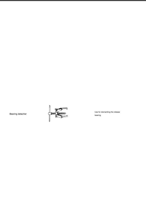
Preparation
Specified tools
CL-1
Clutch
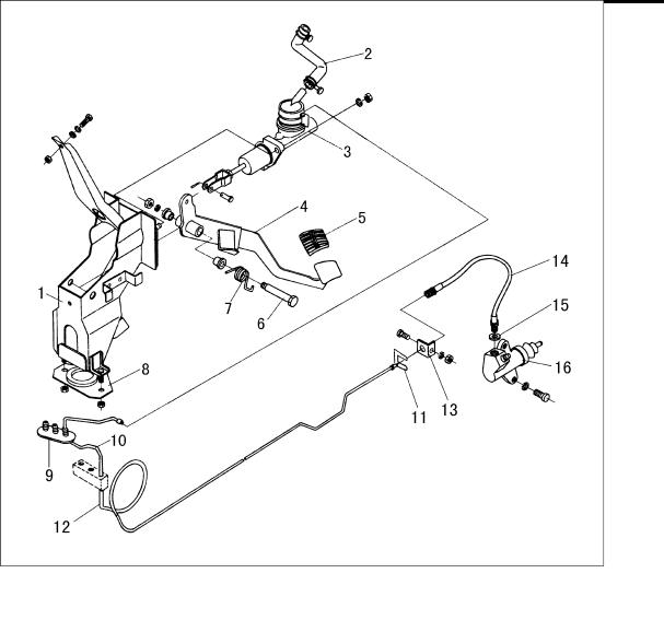
Clutch System
1.Clutch pedal bracket assy |
9.Dustproof |
2.Rubber hose assy--oil reservoir to master pump |
10.Front oil pipe assy |
3.Clutch master pump assy |
11.Spacer |
4.Clutch pedal welding assy |
12.Rear oil pipe assy |
5.Pedal jacket |
13.Clutch rear bent pipe bracket |
6.Clutch pedal shaft |
14.Hose assy |
7.Clutch pedal return spring |
15.Gasket |
8.Lower fixed board |
16.Clutch slave pump assy |
CL-2

Clutch
Adjusting Clutch Pedal
1.Adjust the pedal height by means the spacing screw.
Height of the clutch pedal H
160~170mm
2.Adjust the clutch pedal free play by master cylinder push rod: Loose the locking nut when adjusting, turn the master cylinder push rod, then make the push rod withstand the spacer and screw off for 1/5~1/2 circles, screw down the locking nut at last.
Pedal free play A
30~50mm
Bleeding Procedure
Bleed air according to the following procedure:
Carefully monitor fluid levlel at master clinder during bleeding operation.
1.Fill in reservior with rocommended brake fluid.
2.Connect a transparent plastic tube to air bleeder valve.
3.Fully depress clutch pedal several times.
4.With clutch pedal depressed, open bleeder valve to release air.
5.Tighten the bleed valve.
6.Repeat steps 3 and 5 above until brake fluid flows from air bleeder valve without air bubbles.
CL-3

Clutch
Clutch Control System
Clutch master pump
1.Oil intake joint |
11.Limit screw |
2.Dual wire clamp |
12.Rubber cup |
3.Pump body |
13.Piston |
4.Return spring |
14.Retainer ring |
5.Piston oil intake valve return spring seat |
15.Push rod thread fork |
6.Piston oil intake valve return spring |
16.Hex thin nut |
7.Piston oil intake valve oil seal |
17.Push rod spacer |
8.Piston oil intake valve |
18.Push rod |
9.Oil pipe joint |
19.Dustproof |
10.Limit screw seal ring |
|
CL-4
Clutch
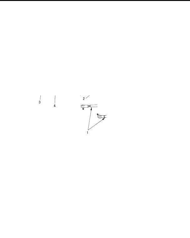
Disassembly and assembly
Push pistion into cylinder body with screwdriver when removing or tightening valve stopper screw.
Align groove of piston assembly and valve stopper when installing valve stopper screw.
Clutch slave pump
1.Slave pump push rod nut |
5.Rubber cup |
2.Shield |
6.Pump body |
3.Push rod |
7.Oil drain screw plug |
4.Piston |
8.Dustproof |
Inspection
1.Check rubbing surface of slave cylinder for wear, rust or damage.
2.Check piston cup for wear or damage. Replace if necessary.
3.Check dust cover for cracks, deformation or damage. Replace if necessaty.
4.Check piston spring for wear or damage. Replace if necessary.
CL-5
Clutch
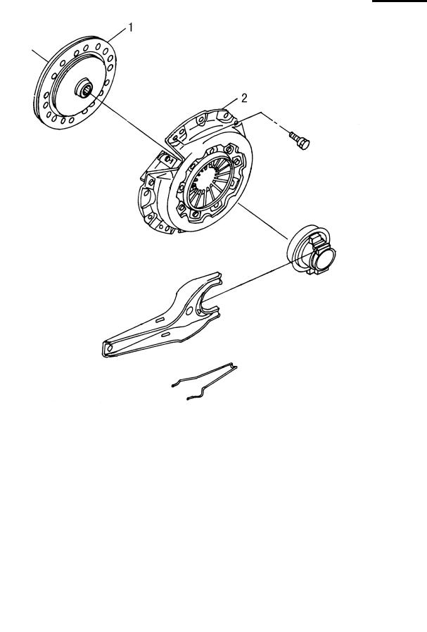
Clutch Release Mechanism
1.Clutch driven disc |
2.Clutch cover and pressure plate |
Removel and installation
Install retainer spring and spring holder.
CL-6

Clutch
Remove release bearing.
Install release bearing with suitable tolerance.
Inspection
Check whether the release bearing has crackle and wear. The release bearing should run smoothly and noiselessly. Change it if necessary.
Check whether the surface of the release bushing and release fork has wear, damage and corrosion. Change them if necessary.
Lubrication
Lubrication the fit surface and the friction surface of the bushing and fork with recommended grease.
Warning
•Too much grease might result in damage to the clutch driven disc
Clutch Driven Disc and Pressure Plate
CL-7

Clutch
Clutch Driven Disc
Check
Check the wear of the driven disc;
The wear limit between the friction facing and rivet head: 0.3mm.
Check up the spline tooth gap and its deviation for the driven disc;
Check whether the driven disc has been burnt, discolored or polluted with oil or grease. Change it if necessary.
Assembling
Apply some grease on the connecting surfaces and spring.
Note:
•Most grease might result in damage to the driven disc surface.
Clutch Pressure Plate and Flywheel
Checking and adjustment
·Check the height and unevenness of diaphragm spring.
·Put the feeler (T=0.2) on the space bush during checking up the height of the diaphragm spring.
Height of the diaphragm spring 41~43mm
·If the height of the diaphragm spring is measure beyond the set range, change the pressure plate surely.
·Check the worn or damage condition for the diaphragm spring support washer by rocking the pressure plate by listening to the vibration sound. Judge whether there is light crackle sound by patting the rivet gently. Change the pressure plate if necessary.
·Check whether the pressure surface of the pressure plate is burnt or dirtied. Remedy it with the emery paper.
CL-8

Clutch
·Check whether the matching surface of the pressure plate and driven disc has deformation or damage. Change them if necessary.
·Adjust the unevenness of the diaphragm spring with tool.
Flywheel check
·Check whether the working surface of the flywheel is burnt or discolored. Remedy it with the emery paper.
Check its surface for planeness.
Clutch cover and flywheel
When assemble the clutch pressure plate and driven disc, insert the special tool into the spline hole of the driven disc. (using for central position)
·Tighten the fixed bolts the clutch cover.
·Tighten the bolts as cross procedure shown in the figure with two steps.
Service Data and Specifications
Clutch driven disc
Outside diameter: |
260mm |
|
Thickness: |
8.0 ± 0.3mm |
|
Checking and adjusting |
||
|
|
|
Pedal height |
|
160~170 |
|
|
|
Pedal free travel |
|
30-50mm |
|
|
|
The datum measured is referred to distance between the floor surface and the pedal.
Clutch driven disc
Wear limit form the friction surface to the |
0.3mm |
|
rivet head |
||
|
||
|
|
|
Effective thickness of the friction lining |
1.2mm(Nominal size) |
|
|
|
Clutch pressure plate
Diaphragm spring height: 41-43mm
CL-9

Clutch
CL-10
Transmission
|
MT |
TOC |
|
Technical Performance Overview.......................................................... |
MT-1 |
Service and Maintenance Notes for Transmission ............................. |
MT-1 |
Trouble and Troubleshooting.................................................................. |
MT-1 |
Disassembling Procedures and Notes for Transmission Assembly MT-2
Check and Repair .................................................................................... |
MT-11 |
Reassembling Procedures and Notes for Transmission AssemblyMT-13

Transmission
Transmission
Technical Performance Overview
Structure pattern
The 17G1A8-25 transmission is a mechanically manual transmission with 5 forward speeds and 1 reverse speed. All the forward speeds are synchromeshed. 5th speed is overdrive gear. All of them apply skew cylindrical gear engagement and the gear shifting is smooth.
Gear ratio
1st speed |
2nd speed |
3rd speed |
4th speed |
5th speed |
Reverse speed |
|
|
|
|
|
|
5.016 |
2.672 |
1.585 |
1.000 |
0.77 |
4.783 |
|
|
|
|
|
|
Odometer ratio:14/4.
lubricating oil
Brand: Manual transmission oil LAN-1 85W/90 or engine oil SAE 5W-30.
Oil volume: 2.7L
Service and Maintenance Notes for Transmission
1.Add lubricating oil as specified before mounting the transmission on the vehicle.
2.During shifting operation, depress the clutch pedal to the bottom. Before shifting into the reverse speed, stop the vehicle completely.
3.When crossing a river or operating in mud, prevent water form entering into the transmission. Otherwise, oil must be replaced.
4.The Service and maintenance of transmission shall follow the service and maintenance instructions for lightduty vehicles. Replace the lubricating oil of transmission periodically. When replacing the oil, loosen the oil drain plug at the lower part of transmission housing. After draining the oil in the housing, tighten the oil drain plug. Fill the lubricating oil into the transmission through the filling plug port on transmission shifting cover until it reaches the lower edge of filler port.
Trouble and Troubleshooting
Trouble |
Phenomenon |
Probable case |
Judgement &Trouble shooting |
|
|
|
|
|
|
|
|
|
1. Check the operating system to see whether |
|
|
|
|
the shifter rock arm of transmission is pushed |
|
|
|
|
in position, or dismount the transmission cover |
|
|
|
|
and push the fork by hand to engage the gear, |
|
|
|
1.Wear of fork shaft circular groove |
check the engagement condition. |
|
|
|
and interlock pin, plastic deforma- |
2. If not completely engaged,check the fork for |
|
|
1.The transmission |
tion of lock ball spring. |
deformation or overwear of working suface. |
|
Disengagement |
shifts into neutral |
2.Wear of fork working surface. |
3. If the gear sleeve is completely engaged, |
|
automatically during |
3.Wear of connecting cone for syn- |
check the gear sleeve and the back taper part of |
||
|
||||
|
driving. |
chronizer toothed ring and gear |
connecting tooth for wear. |
|
|
|
sleeve. |
4. If the clearance is too large when stirring the |
|
|
|
4.Axial looseness of gear. |
fork, check the fork shaft groove to see whether |
|
|
|
|
the locating spring is worn or faulty. |
|
|
|
|
5. Check the 2nd shaft nut of tightening flange |
|
|
|
|
for looseness, if so, the axial position of 2nd |
|
|
|
|
shaft gear will change. |
|
|
|
|
|
MT-1
Transmission
Trouble |
Phenomenon |
Probable case |
Judgement &Trouble shooting |
|
|
|
|
|
|
|
1.Without the failure |
1.Severe wear of interlock pin. |
|
|
The gear couldn't |
of clutch,shifting is |
|
||
2.The fork head of internal speed |
|
|||
difficult with serious |
|
|||
be engaged prop- |
selective rocker arm is sevrely worn |
1.Check the faulty area and remove the failure. |
||
pound or disengage- |
||||
erly. |
or damaged, or separate from shifter |
|
||
ment at some gear is |
|
|||
|
small rocker arm groove. |
|
||
|
hard. |
|
||
|
|
|
||
|
|
|
|
|
|
|
1.Some individual gear and tooth is |
|
|
|
|
broken. |
1.Disassemble,inspect, clean or replace dam- |
|
|
1.Regular pound |
2.Gear clearance is increased or gear |
||
Noise |
aged gear or bearing. |
|||
2.Even noise. |
is damaged. |
|||
|
2.Replace or add oil. |
|||
|
|
3.Bearing is worn. |
||
|
|
|
||
|
|
4.Lubricating oil is not sufficient. |
|
|
|
|
|
|
Disassembling Procedures and Notes for Transmission Assembly
Disassembling procedures of transmission from the vehicle
Disassembling sequence:
1.Operating flexible shaft 2.Odometer driveing flexible shaft 3.Drive shaft
4.Parking brake assembly 5.Starting motor 6.Transmission assembly
MT-2
Transmission
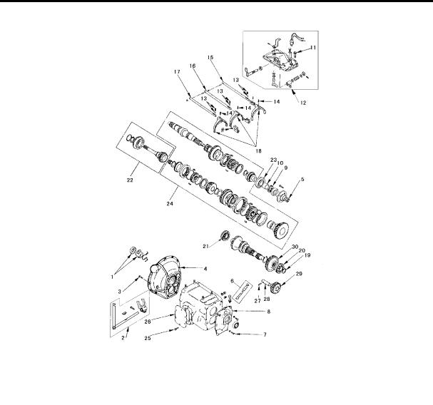
Disassembling sequence and notes for transmission
Disassembling sequence:
1.Clutch release bearing assembly
2.Clutch release fork shaft and release fork arm assembly 3.Clutch case connecting bolt, 9.8 grade
4.Clutch case 5.2nd shaft nut
6.Odometer flexible shaft sleeve sets 7.Connecting bolt, 9.8 grade
8.Rear cover 9.Odometer drive gear 10.Distance sleeve
11.Connecting bolt, 9.8 grade 12.Cover assembly
MT-3
 Loading...