

DongFeng DFA1101GZ5AD6J-907 Operational Manual

DFA1101GZ5AD6J-907
Light Commercial Truck
Operation Manual
DONGFENG AUTOMOBILE CO., LTD.
2006, 05

Foreword
Foreword
Thank you for purchasing the DFA1101GZ5AD6J-907 light
commercial truck that manufactured by DONGFENG AUTOMOBILE
CO., LTD of the People's Republic of China.
This manual contains necessary procedures and instructions for the
operation, inspection and maintenance for your DFA1101GZ5AD6J-907
truck.
This vehicle is equipped with the EQB140-20 DONGFENG Cum-
mins diesel engine which could reach the European II displacement
standard.
To obtain the optimum performance from your new vehicle is the
common goal for all of us, and it depends largely on your care and
familiarity of the operation and maintenance of the vehicles. We
sincerely hope that you read this manual thoroughly, and make sure that
you are familiar with the operation and maintenance before you using
the new truck.
The manual is a part of your vehicle. Please keep it with your truck.
The information and figures in this manual are correct when publishing.
Due to continuous improvement on our vehicles, maybe there are some
instructions in the manual that does not accord with the actual vehicles.
Please inquire when you get some problem.
The Application Section of Testing Department, Commercial product
R&D Institute of DONGFENG AUTOMOBILE CO., LTD. is in charge of
compiling this manual. DFAC reserve the right to make changes at any
time without notice
As for vehicle saling, maintaining or spare parts purchasing, please
consult with the local agency
The manual uses the legal unit.
.
.
DONGFENG AUTOMOBILE CO., LTD.
2006. 05
1
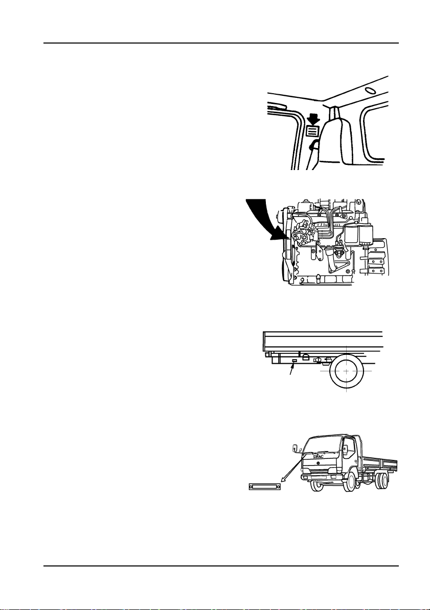
Truck Nameplate
Truck Nameplate Position
Engine Nameplate Position
Truck Nameplate
VIN Position
1—1

Table of Content
Table of Content
Truck Nameplate......................................................................1-1
Truck Nameplate Position ........................................................ 1-1
Engine Nameplate Position...................................................... 1-1
VIN Position............................................................................... 1-1
Main Technical Specifications ............................................2-1
Main Technical Specifications and Structure Features......... 2-1
Operational Data ....................................................................... 2-2
Engine Parameter...................................................................... 2-2
Chassis Type and Structure Parameter ................................. 2-3
Construction and Operation ...............................................3-1
Arrangement of the Cab .......................................................... 3-1
Doors.......................................................................................... 3-2
Seats.......................................................................................... 3-3
Instruments................................................................................ 3-4
Indicators ................................................................................... 3-6
Keys............................................................................................ 3-9
Key Switch................................................................................. 3-9
Light Combination Switch...................................................... 3-10
Power Switch........................................................................... 3-13
Exhaust Brake Switch............................................................. 3-13
Air Horn and Electric Horn Shift Switch ............................... 3-14
Air Drier Switch ....................................................................... 3-14
Dome Lamp and Glove Box ................................................... 3-14
Cab Skylight ............................................................................ 3-15
Air Conditioning System ........................................................ 3-15
Levers, Steering Wheel and Accessories............................. 3-16
Tilting Cab................................................................................ 3-21
Vehicle Starting......................................................................4-1
Engine Starting.......................................................................... 4-1
Engine Starting (when the cab is tilted) ................................. 4-2
1

Running-in and Maintenance of New Vehicle ............... 5-1
Before Running-in .....................................................................5-1
Running-in Period......................................................................5-2
After Running-in.........................................................................5-2
Driving Recommendations................................................. 6-1
Driving on a slope .....................................................................6-2
Clutch Operation .......................................................................6-2
Double-foot-clutch Method for Shifting...................................6-3
The Use of Warning Triangle ....................................................6-3
Parking........................................................................................6-4
Vehicle Inspection ............................................................ 7-1
Driver's Daily Inspection ..........................................................7-1
Vehicle External Inspection .....................................................7-2
General Maintenance ......................................................... 8-1
Air Filter ......................................................................................8-1
Diesel Oil Prefilter......................................................................8-2
Fuel Filter and Fuel-water Separator........................................8-2
Oil Filter ......................................................................................8-2
Fuel Tank Draining.....................................................................8-3
Fuel Pump .................................................................................8-3
Exhaust GasTurbo Supercharger.............................................8-4
Air Drier ......................................................................................8-6
Check the Oil Level, and Refill the Clutch Oil Reservior .......8-6
The Transmission Lubricating Oil........................................... 8-6
The Rear Axle Main Reductor Lubricating Oil ....................... 8-7
Power Steering Lubricating Oil ................................................8-8
Battery Checking and Maintenance ........................................ 8-9
Fuse ..........................................................................................8-10
Suspension ..............................................................................8-10
Tire Rotation............................................................................ 8-11
Clean and Replace the Wiper Blades.....................................8-12
General Adjustment............................................................ 9-1
2

Table of Content
Using Engine in a Environmental Protection Standard........ 9-1
Drain Water Out from the Cooling System ............................. 9-2
Check the Opening Temperature of the Thermostat.............. 9-2
Adjustment of Fan Belt............................................................ 9-3
Pump Fuel Manually and Bleed Air Out of Fuel Supply System
9-4
Water-leak Hole of the Water Pump......................................... 9-4
Air Valve Clearance Adjustment .............................................. 9-4
Adjustement of Clutch.............................................................. 9-5
Air Release of Clutch............................................................... 9-6
Adjustment of Brake Clearance.............................................. 9-7
Brake system............................................................................ 9-9
Adjustment of wheel hub bearing .......................................... 9-9
Adjustment for the front wheel hub bearing ....................... 9-10
Adjustment for the front wheel hub bearing ........................ 9-10
Adjustment of Free Play of Steering Wheel.......................... 9-10
Adjustment for Toe-in ............................................................. 9-11
Maintenance Schedule ..................................................... 10-1
Engine ..................................................................................... 10-1
Clutch ....................................................................................... 10-2
Transmission ........................................................................... 10-3
Brake System .......................................................................... 10-3
Steering System ...................................................................... 10-4
Suspension System................................................................ 10-5
Propeller Shaft........................................................................ 10-5
Axle and Wheel....................................................................... 10-6
Others...................................................................................... 10-6
Main Adjusting Data ............................................................... 10-7
Fuel.......................................................................................... 10-8
Grease Application Place and Schedule.............................. 10-8
Lubricant and Vehicle Used Fluid.......................................... 10-9
Engine Lubricant................................................................... 10-10
Gear Oil .................................................................................. 10-11
Transmission Gear Oil ......................................................... 10-11
Lubricating Grease .............................................................. 10-11
Shock Absorber Oil............................................................... 10-11
3

Clutch Boost Liquid...............................................................10-11
Engine Anti-freeze Fluid (cooling fluid).............................. 10-11
Capacity Data .........................................................................10-12
Tightening Torque .............................................................. 11-1
Engine...................................................................................... 11-1
Chassis .................................................................................... 11-2
Attached Drawing .............................................................. 12-1
Electric System Drawings...................................................... 12-1
4
Main Technical Specifications
Main Technical Specifications
Main Technical Specifications and Structure Features
●
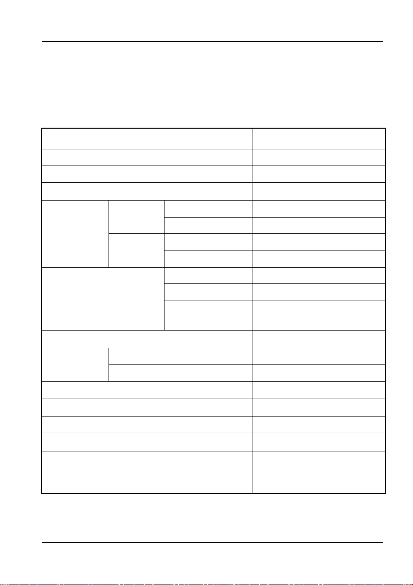
General Data
Vehicle Model 5ADDFA1101GZ 6J-907
Rated Loading Weight (kg) 4990
Curb Weight (kg) 4420
Gross Weight (kg)
Load Distribution (kg)
Overall Dimension (mm)
Wheel Base (mm)
Wheel
Tread (
Front/Rear Overhang (mm) 1270/2380
Approach angle/Departure angle
Min. Ground Clearance (mm) (Full-load) 240
Min. Turning Diameters (m)
Structure Features
mm)
Front axle
Rear axle
Front wheel 1831
Rear wheel 1640
No-load 2235
Full-load 3195
No-load 2185
Full-load 6410
Length 8350
Width 2330
Height (no-load,
to cab top)
Cab over engine, single
row, equipped with
EQB140-20 engine
9605
2395
4700
5.5 2 °/ 11°
19
2—1
Main Technical Specifications
Operational Data
(km/h)Max speed
Max gradability (Full-load on dry and hard
road, the slope length is over 15m)
Ability of parking on the slope
105
≥ 30%
≥ 20%
100km fuel consumption (L) ≤ 13
Max continuous running distance (km)
500
RC-0#(summer), RC-
Fuel type
10#(
winter) vehicle used
light diesel oil
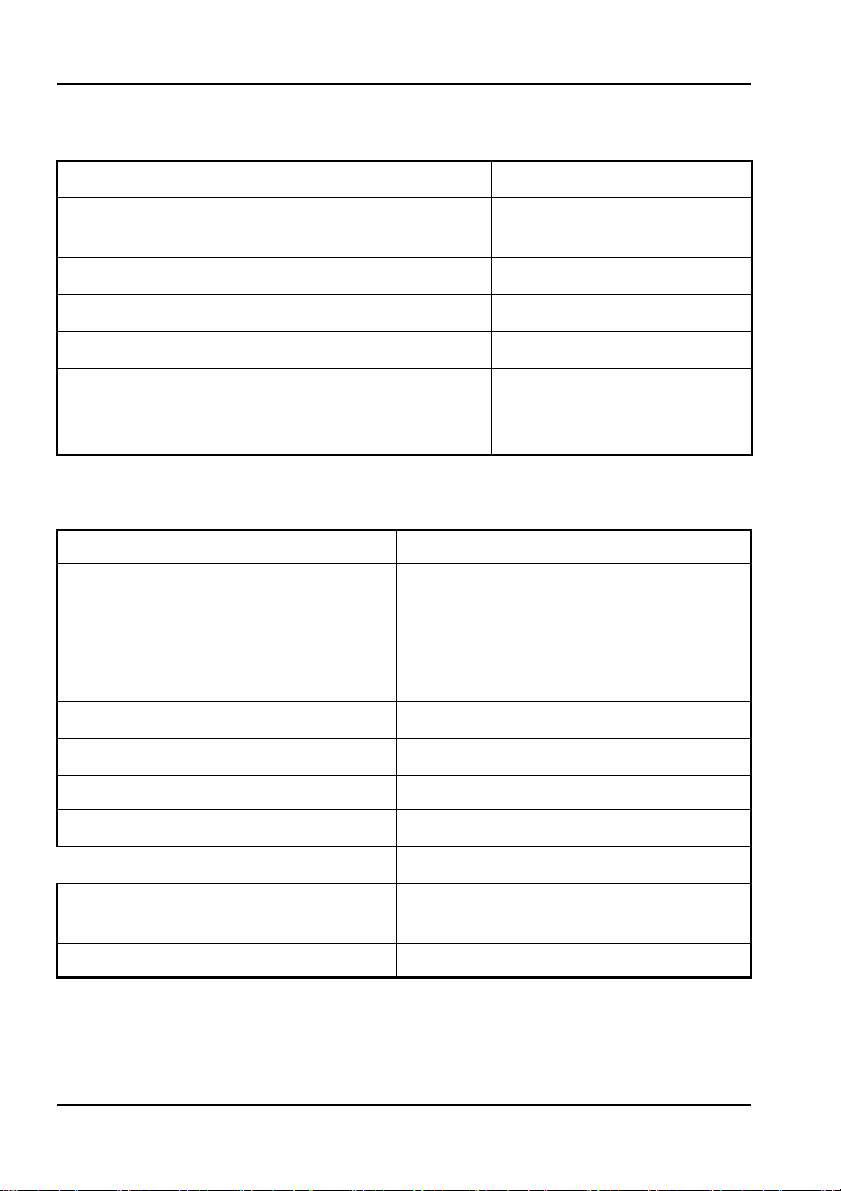
Engine Parameter
Model EQB140-20
4 in-line cylinders, supercharging
and intercooling, direct injecting
Type
× Stroke (mm × mm)Bore 102 × 120
Displacement (L)
DONGFENG Cummins diesel
engine, reach the European II
displacement standard
3.92
Compression ratio 17.3:1
Rated power (kW/rpm)
Rated torque (N.m/r/min)
Min. specific fuel consumption
(g/kW.h)
103/2700
502/1500
210
Injecting order 1-3-4-2
2—2

Main Technical Specifications
Chassis Type and Structure Parameter
1.Clutch
Ø350 mm single , dry disc, hydraulic remote control.
2.Transmission
Manual mechanical transmission, six gears forward, one reverse,
ynchronizers on 2nd to 6th gear. There is a take-off window on the
with s
right side, controlled by flexible shaft.
Speed ratio:
Gear
Speed
ratio
Ⅰ
Ⅱ Ⅲ Ⅳ Ⅴ Ⅵ
7.454 4.823 3.075 1.976 1.480 1.000 6.709
R
3.Propeller shaft
Cardan universal joint, depart into two parts..
4.Front axle
Forging, I-beam axle.
Front wheel aligner:kingpin inclination 7°
caster 2°
camber 1°
toe-in 0~5mm
5.Drive axle
Founding axle housing, single-stage and double-curved gear
reductor, fully floating axle shaft
.
Final drive: 4.33
6.Suspension system
Both front and rear suspension are dependent, laminated leaf-
spring, with an auxiliary spring on rear suspension.
Hydraulic telescopic damper: Equipped on the front suspension
Number of spring leaf: Front: 11, Rear 13+8.
7.Wheel
2—3

Main Technical Specifications
Single tyre on the front axle, double tyre on the rear tyre, and a
spare tyre on the spare tyre carrier hang under the rear end of the
frame.
Tyre:8.25-20
Tyre inflating pressure:
Front wheel is 490kPa and rear wheel is 560kPa, while the allow-
able inflating pressure is 630kPa.
8.Steering system
Circulating ball type with power steering.
Max front wheel turning angle (inside/outside): 40°/32°
9.Brake system
Service brake:dual-circuit, air brake system, and front and rear
brake are self-adjustable, cam, air-operated, drum brake with the
exhaust auxiliary brake system.
Parking brake:spring brake controlled by manual-operated valve
through air pipes.
10.Frame
Ladder type, longitudinal is grooving section and riveted by several
crossbeams, part of the frame has stiffening plate.
11.Electric equipment and instruments
Single, negative earthed line, 24V.
Battery:6-QW-90DF
Starter:24V, 3.7kW
Alternator:45A, 28V
Main switches:
Power switch, combined switch, ignition switch, assistant starting
switch, heater switch, etc.
Instruments:
Speedometer and odometer, water temperature gauge, fuel gauge,
air-pressure gauge, oil pressure gauge, etc.
Indicators:
Water temperature indicator, oil pressure indicator, fuel level warn-
ing indicator, oil pressure warning indicator, turning signal indicator,
2—4

Main Technical Specifications
charge warning indicator, parking indicator, water overheat or level over
low warning indicator, reversing warning indicator, electric horn,
etc.
Lamps:
Head lamp, front combined lamp, fog lamp, turning signal lam p,
license lamp, tail
combined lamp, front clearance lamp, rear clearance
lamp, side marker lamp, etc.
12.Cab
New developed, all metal structure, tilting, wide cab with single row
and a sleeper. Interior trimming has two types: standard and luxury. The
driver's seat can be adjusted for ward and backward. The driver and the
assistant's seats are fitted with 3 point-seat belt, the middle seat is fitted
with 2 point-seat belt. The cab is equipped with full-scope windshield,
sun shield, inner rear view mirror, and radio cassette, etc.
13.Tools equipment
Every commercial vehicle is equipped with a set of tools.
2—5
Construction and Operation
Construction and Operation
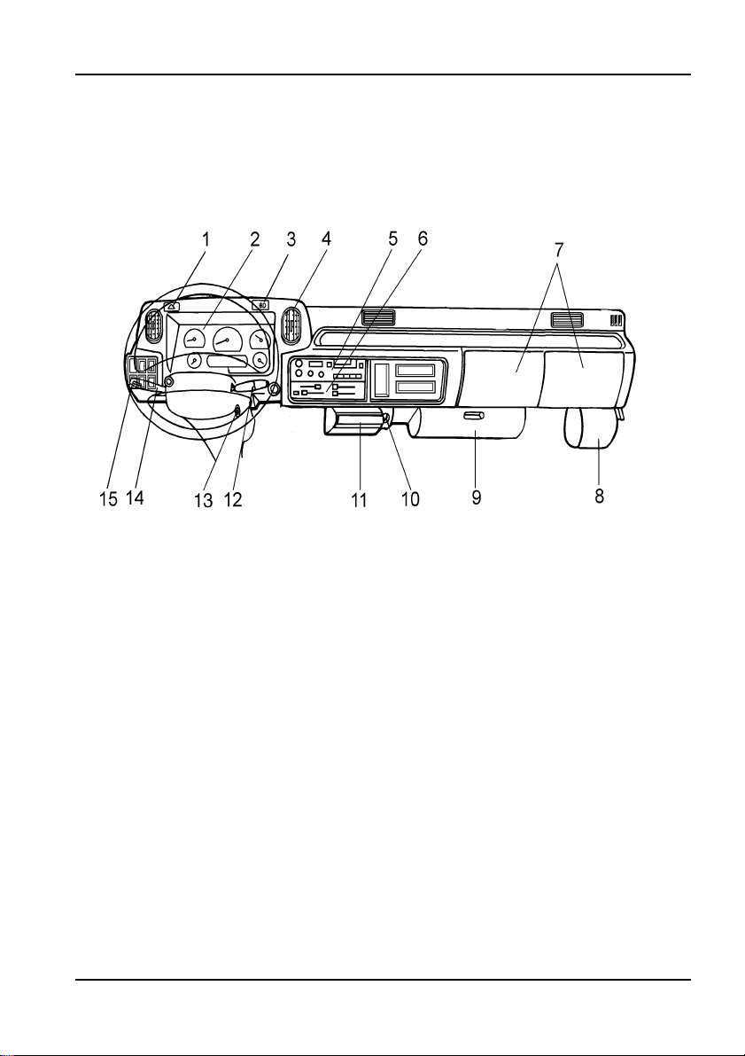
Arrangement of the Cab
1. Hazard waring lamp switch
2. In strument panel
3. Front fog lamp switch
4. Wind channel
5. Radio cassette
6. Heater and air-conditioner switch
7. Glove box
8. Windshield washer fluid reservoir
9. Fuse box
10. Cigarette lighter
11. Ash tra y
12. Windshield wiper and washer controlling rod
13. Ignition lock
14. Combined light switch
15. Combination switch
3—1
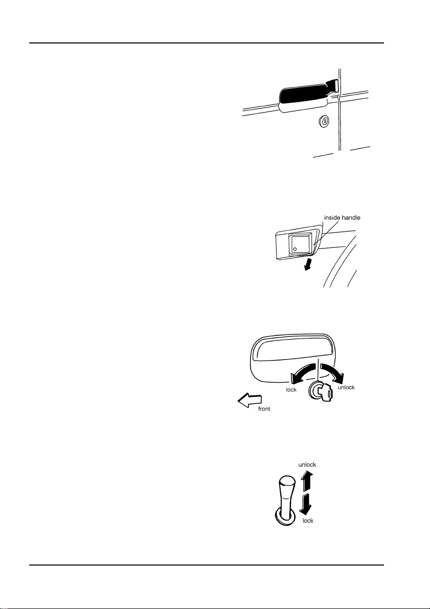
Doors
● Opening doors
From the outside
From the inside
Note:
After closing the door,please double check
whether the door is really closed. Driving with
the door half closed can be very dangerous.
● Closing doors
From the outside
Turn the key forward to lock the
door, while turn it backward to unlock
the door.
Construction and Operation
From the inside
Set the lock ball to the locked
place, and pull the door handle to close
the door.
3—2
Construction and Operation
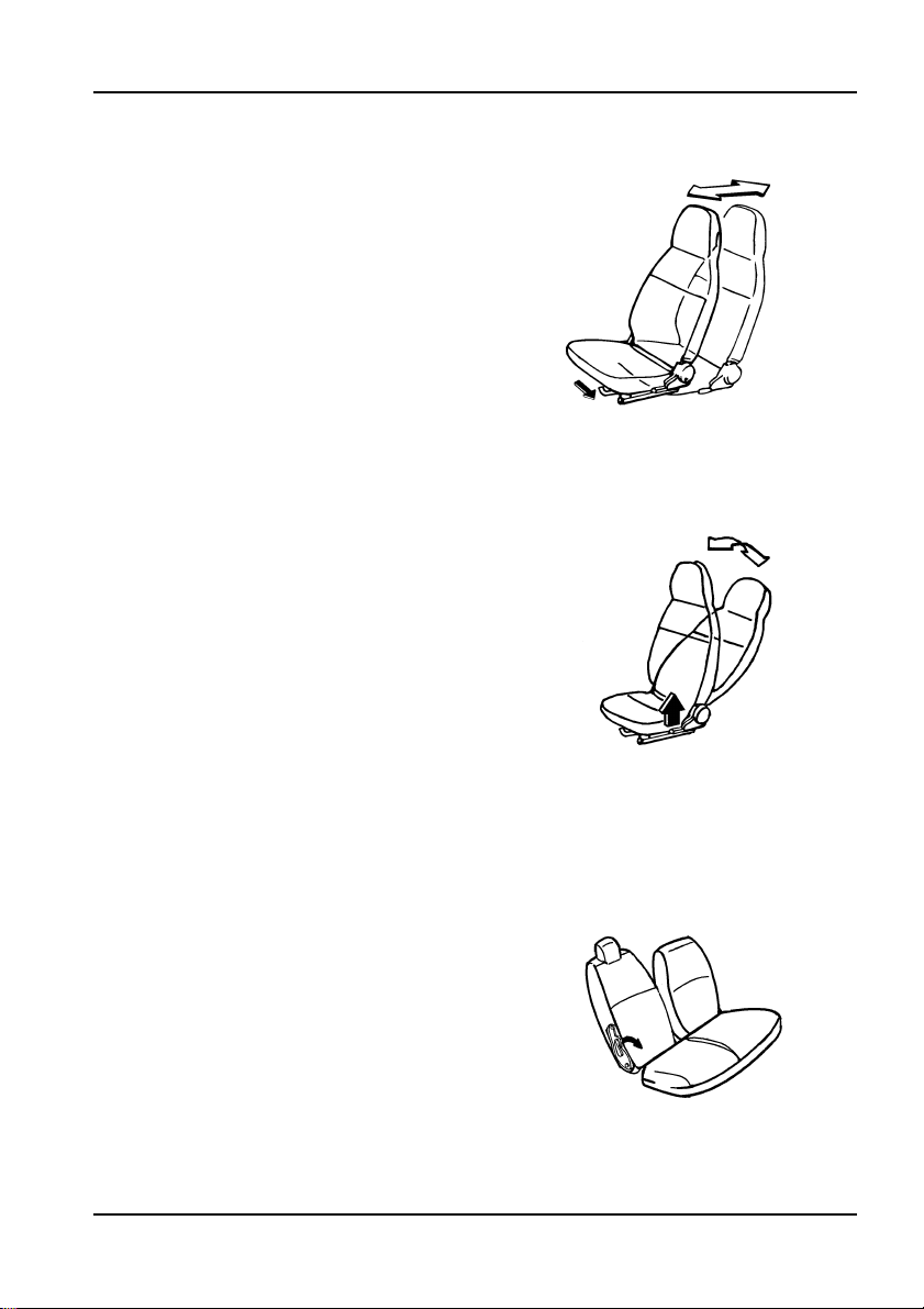
Seats
● Driver's seat forward and back-
ward adjustment
Raise the adjusting lever on the
front side of the seat, and move the
forward and backward till to the
seat
optimum, then release the adjusting
lever and
position.
lock the seat in the desired
● Driver's seat back angle adjust-
ment
Raise the adjusting lever on the left
side of the seat,
back to an angle most appropriate for
holding the steering wheel
elease the lever to lock the seatback in
r
the desired position.
and adjust the seat
, then
● Assistant's seat back adjustment
Turn the knob located on the right
side of the seat
adjusted to the desired position or
putted down face to the seat.
, the seatback will be
3—3
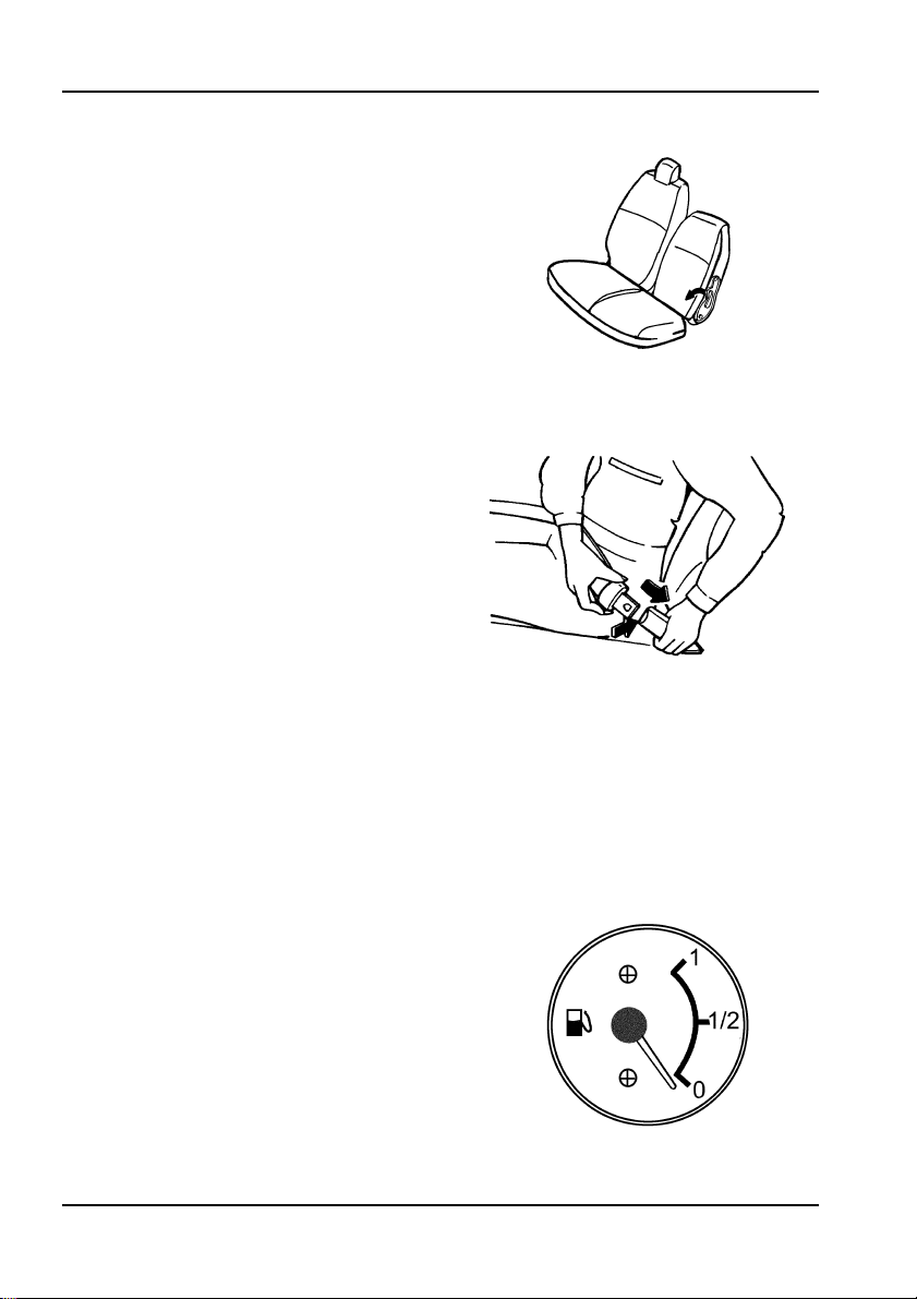
● Center seat back adjustment
Turn the knob located on the left
side of the seat, the seatback will be
adjusted to the desired position or
putted down face to the seat
.
● Safety belts
Slowly pull out the safety belt and
make it throught your body from the left
side of your neck to the right side of
your waist and press the button, then
insert the locking hook into the latch
hook. Adjust the length of the safty belt
to the optimum.
Note:
Adjust the position of the seat correctly;
Make sure that the safty belt is not winded
or rubbed by hard edge, and far away from the
chemical and battery acid;
One belt for one person;
After being overused, invalid or damaged,
the whole belt should be changed;
If the safty belt retractor does not work well,
the whole belt should be changed immediately.
Construction and Operation
Instruments
1.Fuel Gauge
The fuel gauge use to indicate the
approximate level of fuel remaining in
the fue tank. The needle will change
because of vehicle braking, turning,
accelerating or climbing.
3—4
Construction and Operation
Note:
Do remember refill the fuel tank with clean
fuel before the gauge indicates that the fuel has
been used up.
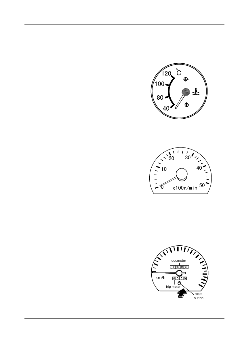
2.Water Temperature Gauge
The gauge indicates the engine
water
temperature. Its needle will
change
because of atmospheric
temperature and driving condition.
Note:
Be sure to stop the vehicle as soon as
possible when the needle of the gauge beyond
the normal range.To run the vehicle with a
overheated engine is extremely harmful to the
engine.
3.Tachometer
The needle of the tachometer
indicates the engine speed in
revolutions per minute. The red zone
indicates a range of critical engine
speed. Be sure to always keep the
indictor below this critical zone. The
green zone indicates the range for the
most economical engine operation.
Driving under this green zone will save
fuel and extend the sevice life of the
engine.
4.Speedometer
The speedometer indicates the
speed of the vehicle in kilometers per
hour. The odometer indicates the
accumulated driving distance in
kilometers.
The trip meter is used to represent
the running distance of a day or a
trip.Do remember to press the reset
button to delete the numbers before
3—5
you use it. The most right number has a
unit of 0.1km.
Note:
Do not press the reset button during the
driving period.
Do not pull or turn the reset button when
press it.
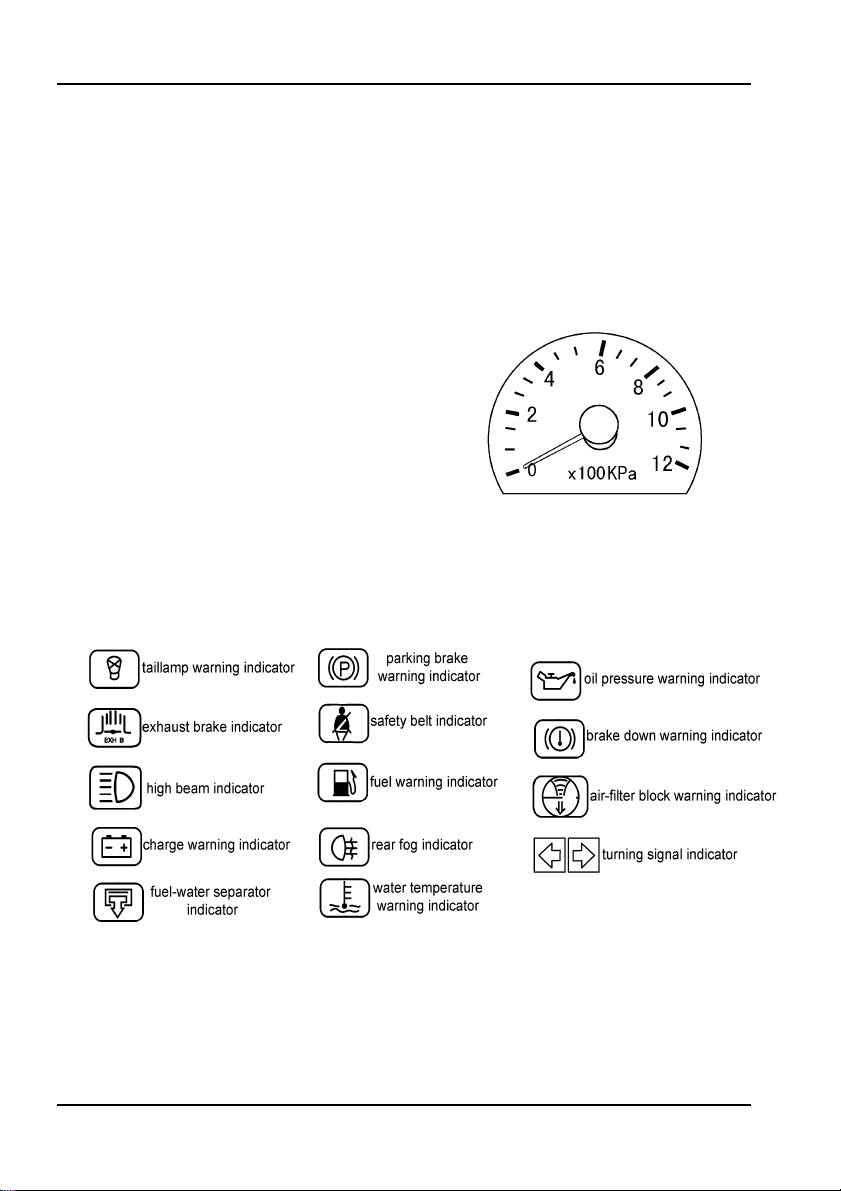
5.Air-pressure Gauge
There are two gauges here, one for
front brake system, the other for rear
brake system. The range of the
indicator is from 0~12x100kPa
, while
0~4x100kPa is in red zone, and under
that condition the vehicle cannot be
started. Only when the indications of
the two needles all over 4x100kPa can
the vehicle be started.
Indicators
Construction and Operation
1.Taillamp Warning Indicator
The indicator will lighten when any
of the tail
lamp (exclude the turning
lamp) is in trouble.
3—6

Construction and Operation
2.Exhaust Brake Indicator
The indicator wil lighten when the
exhaust brake is switched on.
3.High Beam Indicator
The indicator will lighten when the
high beam is used, and if the passing
light is used, the indicator will
en.
lighte
also
4.Charge Warning Indicator
The light will lighten when the key
switch is turned on, and will extinguish
when the engine is started and
charging is initiated. If charging is
stopped due to the failure of the
charging system during engine
operation, the light will lighten.
Note:
Never run the vehicle with the warning light
on. This will run down the battery.
5.Fuel-water Separator Indicator
If the sensor of the fuel-water sepa-
rator indicates that the water level is
too high, this indicator will lighten and
remind the driver to drain water.
6.Parking Brake Warning Indicator
The light will lighten when the
parking brake is actuated to aware the
driver that the vehicle is in the braking
condition. The light wil extinguish when
the parking brake stops operating.
Before moving the vehicle, make sure
the light is off.
7.Safety Belt Indicator
The indicator will flash for 7
seconds to aware the driver and
3—7

passengers to use the safty belts when
the ignition lock is placed at "ON"
position.
8.Fuel Warning Indicator
The indicator will lighten when the
remaining fuel is too little to assure the
normal driving. It is used to aware the
driver to refill the tank.
9.Rear Fog Indicator
The light will lighten when the rear
fog lamp is used.
10.Water Temperature Warning
ndicator
I
The light will lighten when the
temperature of the water is over 101 ℃
. At the same time, a buzzer will sound
to make the driver aware that the
engine is in dangerous situation. The
buzzer stops when the key switch is
turned off with the engine stopped.
Construction and Operation
11.Oil Pressure Warning Indicator
The light will lighten when the key
switch is turned on, and will extinguish
after the engine starts. It will be lighted
again when the oil pressure is too low
during the operation of the engine.
Note:
The low pressure of the engine will cause
the damage of the engine.
Never run the vehicle with the warning light
on.
12.Brake-down Warning Indicator
The light will lighten when the level
of the brake fluid drops or the front
3—8
Construction and Operation
brake lining is worn out. Do remember
to refill with brake fuid or chang the
brake lining.
13.Air Filter Block Warning Indicator
When the air filter is blocked, the
indicator will lighten to remind the driver
to clean it.
14.Turning Signal Indicator
This indicator is used to indicate
the working condition of the turning
signal lamp. Switch on it and both the
left and right indicator are flashing.
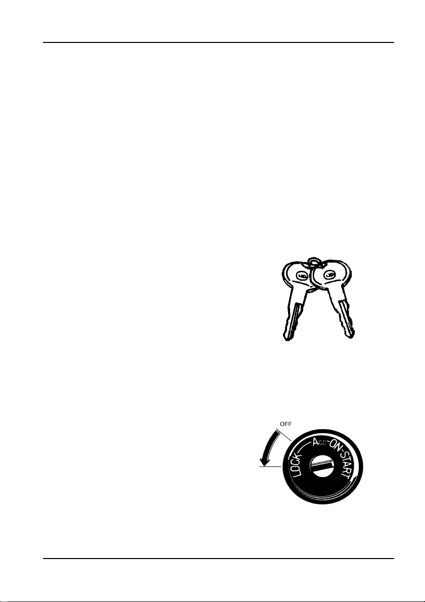
Keys
There are two keys provided that
used to start the vehicle, open or lock
the door.
Key Switch
LOCK: Only the key is set on the
LOCK position can it be inserted or pull
out.
OFF: Turn the key from ON to OFF
to shut-down the engine.
ACC: Set the key at the ACC
position
(such as
cigarette lighter, etc), while the engine
is not operating.
to use any of the accessories
radio cassette, wiper,
3—9
ON: After the engine starting, the
key return from START to ON and the
engine is started normally.
Never turn
the key to any other position while the
engine is running.
START: Set the key to the START
position to start the engine. The key will
return automatically to the ON position
when released from the START
position.
Note:
Never turn the key to the START position
while the engine is running, or else it makes the
starter damage
can the engine be started again.
d. Only after the engine stops
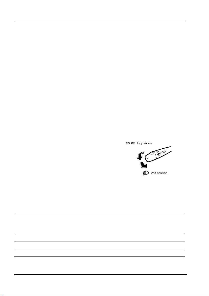
Light Combination Switch
This combined switch is used for
front lamp, tail lamp, head lamp, instru-
ment lamp, licence lamp, passing lamp,
dimmer and turning lamp, etc.
Construction and Operation
1.Light switch
Turn the end knob of the combina-
tion switch lever forward, the lamps
represented in the below chart will illu
-
minate depending on the position of the
switch.
○ ON xOFF
Knob
position
OFF x x x x x x x x
1st position x
2nd position
3—10
Head
Front
lamp
lamp
○ ○ ○ ○ ○ ○ ○ ○
Ta il
Licence
lamp
○ ○ ○ ○ ○ ○ ○
lamp
Instru
ment
lamp
Front
clearan
ce lamp
Rear
clearance
lamp
Side
clearance
marker
Construction and Operation
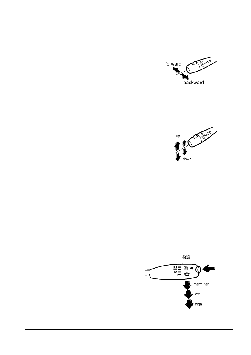
2.Turn signal light switch
Put the control lever forward and
backward to make the left or right turn
signal lamp blinked.
3.Dimmer switch
Put the combined switch control
lever up and down to change from the
high beam to low beam or from the low
beam to high beam. If there is a coming
vehicle, do remember to use it.
4.Passing light switch
The head light high beam will
lighten as long as the lever is being
pulled from the low beam position, and
when releasing the lever, it will auto
-
matically return back to the low beam
position. You can use this to tell front
vehicles that you're going to pass them.
During the normal running condition of
the vehicle, no matter other lights' con
-
dition, if you use the passing light, it will
be on.
5.Windshield Wiper and Washer Switch
When the front windshield is dirty
and needs to wash, press the button on
top of the windshield washer lever, the
washer will operate and the washer
fluid will be sprayed out
continuously.
At the same time, the equipped
intermitted wiper (3-speedtype) is also
3—11
operating. The wiper should be moved
two or three more times after the
washer stop
s. The wiper starts after
pulling the lever backward. It has
intermittent, low and high three speeds.
Release the
button, the washer stops.
Pull the lever to the end of the front, the
wiper stops
Note:
Use of the wiper alone will scratch the
windshield. Be sure to operate it with the washer
when the weather is well.
Do not use the washer without washer
otherwise the washer motor will be
fluid,
damage.
.
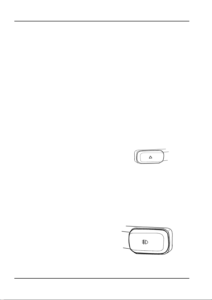
6.Hazard Warning Indicator Switch
Use this switch to warn other
drivers when your vehicle becomes a
traffic hazard
trouble.
urning signal lights are lightened, and
t
the turning signal
source due to mechanical
If switch on it, all left and right
indicator will flash
simultaneously.
Construction and Operation
7.Front Fog Lamp Switch
When this switch is pushed, the
lamps, front lamps and tail lamps all
fog
come on. Use this switch to control the
lights
when driving in a thick fog.
3—12

Construction and Operation
8.Rear Fog Lamp Switch
In the condition that the front fog
light is on, switch on this and the rear
fog lights come on, while switch off, the
rear fog lights will be off.
Power Switch
The rocker switch is used to control
the electromagnetic power switch in the
circuit system
position to turn-on the vehicle circuit
system, and set it to the OFF position
to cut-off the circuit system.
should be
electrical equipments in case the circuit
system is checked or repaired.
Note:
Don't turn off the power switch when the
engine is running.
. Set the switch to the ON
The circuit
switched off to protect other
Exhaust Brake Switch
It is used to control the exhaust
.
brake
3—13
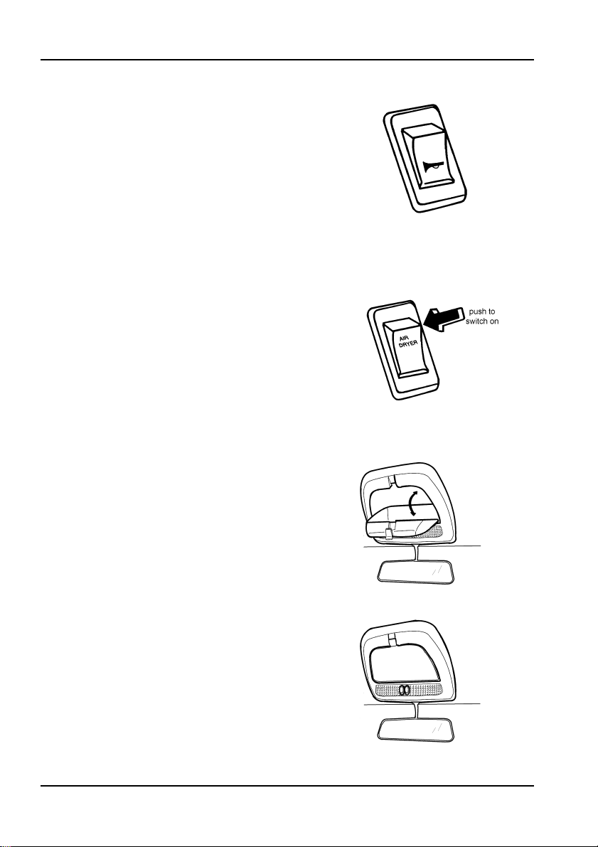
Air Horn and Electric Horn Shift Switch
Choose the air horn or electric horn
as you need.
Air Drier Switch
During raining or snowing days,
switch on the air drier to dry the air in
the brake system to assure the vehicle
brake performance.
Construction and Operation
Dome Lamp and Glove Box
There are one glove box and two
lamps on the inner front of the cab. If
you want to use the glove box, just pull
down the lid.
As for two dome lamps, press the
left button they will lighten no matter the
door is open or not; press the right but
ton they will lighten if any of the door is
opened.
3—14
-
Construction and Operation
Cab Skylight
When you want to introduce some
fresh air into the cab, just push up the
switch of the skylight.
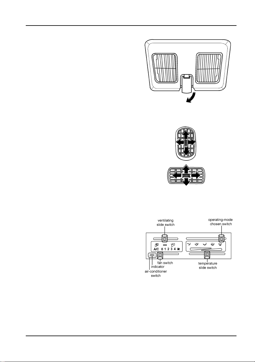
Air Conditioning System
1.Ventilator
Turn the central roller to change
the direction of the airflow.
2.Air-conditioner
Air-conditioner switch
When the air-conditioner is
needed, press this switch and the
indicator light goes on which means the
connection of power supply.
Fan switch
There are five speeds provided,
from 0 to 4. At 0 position, the fan stops,
and the wind will become even stronger
from 1 to 4 speed successively.
Temperature slide switch
It is used to adjust the inside
temperature. Move the slide switch
from left to right and the temperature
will be adjusted from low to hight.
3—15
Ventilating slide switch
-- introducing external air
--circulating internal air
Operating-mode chosen switch
--blowing to your head
--blowing to your feet
--blowing both to your head
and feet
--inside heating and defogging
--inside defogging
Note:
The warm air is heated by the cooling liquid
of the engine. Its temperature depends on the
temperature of the cooling liquid.
Please do not use the heating device too
long when the engine is stop or idle, otherwise it
will wear out the battery and influence the
normal driving.
Do not forget to reduce the transmission
speed and raise the engine revolution during
low speed running, or climbing the long slope, to
reduce the engine load.
You have to wait for 2-3 minutes before
you restart the air-conditioner to extend the
sevice life of the compressor.
You also have to operate the air-
conditioner for 10 or more minutes every month
even in winter to extend its service life.
Construction and Operation
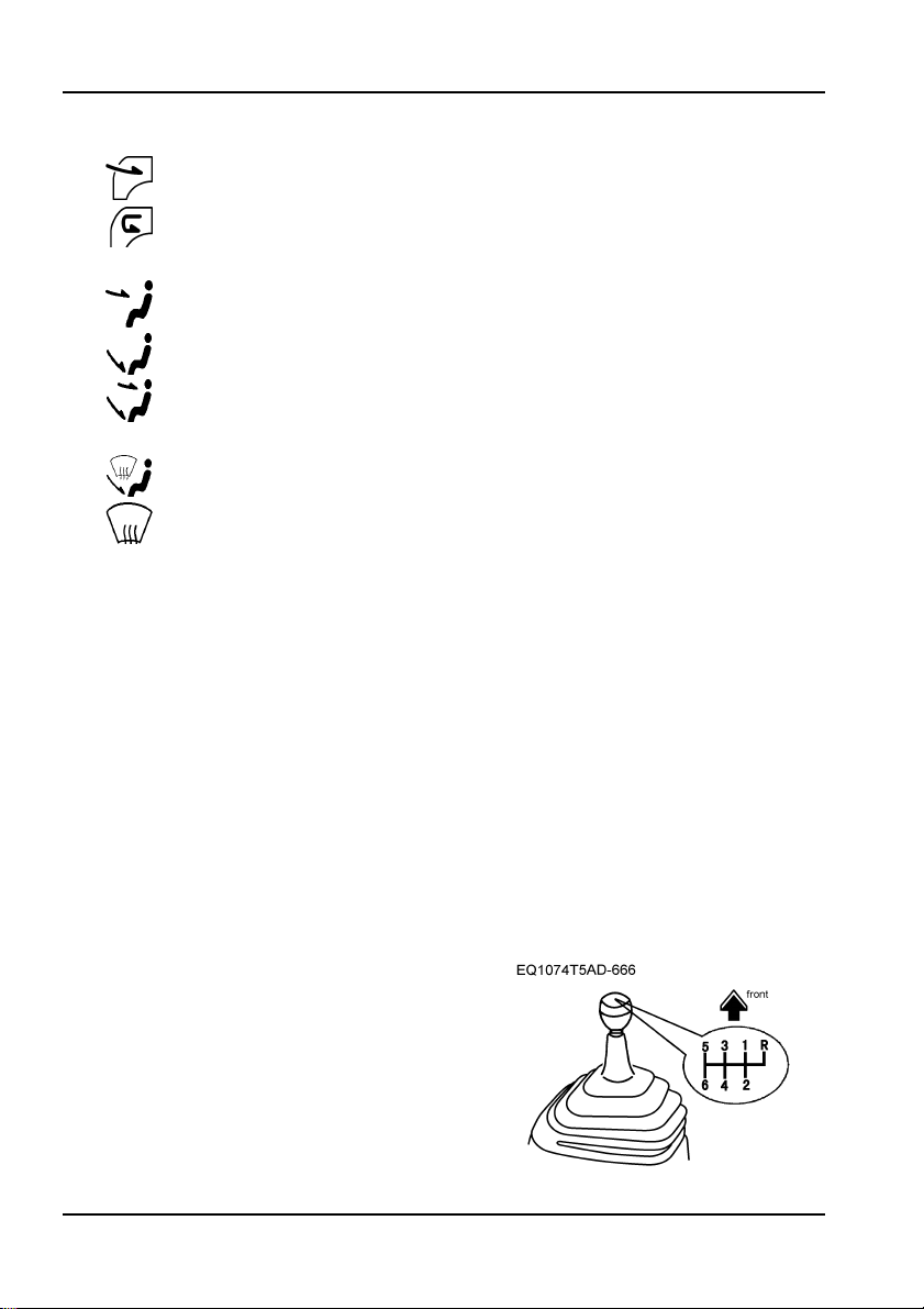
Levers, Steering Wheel and Accessories
1.Transmission gear shift lever
When shifting gears, be sure to
fully
trample down the clutch pedal.
3—16
 Loading...