

DongFeng DFA1101GZ5AD6J-907 Service Manual

DFA1101GZ5AD6J-907
SERVICE MANUAL
DONGFENG AUTOMOBILE CO.,LTD
2006.05

INDEX
General Principles
Clutch
Gearbox
Propeller Shaft
Steering System
Front Axle
Rear Axle
Suspension System
Brake System
Cab
Electric System

General Principles
GL
Table of Conntents
General Principles...........................................................................................GL-1
Operational Instruction ...................................................................................GL-2
Standard Terms...............................................................................................GL-2
Standard Tightening Torque...........................................................................GL-2
Maintenance Rule ...........................................................................................GL-3
Recommended Fuel and Lubricant.................................................................GL-6
Protective Measures while Repairing .............................................................GL-8
Cleaning..........................................................................................................GL-9
Generic Inspection..........................................................................................GL-9
Trouble Analysis...........................................................................................GL-10

General Principles
General Principles
This manual mainly states maintenance and service methods of DFA1101GZ5AD6J-907 light commercial
truck.
To use vehicles safely and efficiently, you need to read the manual thoroughly and make sure that you are
familiar with the items that mark "Note". This is very important.
Due to continuous improvements on our vehicles, maybe there are some instructions in the manual that do
not accord with the actual vehicles.
Maintenance method varies with different skill level, methods, tools and available parts that serviceman
adopts. Any serviceman should firstly take into consideration no harm personal safety and vehicle safety when
working.
As for the maintenance of engine, please refer to service documents offered by DongFeng Cummins Engine
Co., Ltd.
GL-1
General Principles
Operational Instruction
You can neglect the structural differences between the part in the
manual and the corresponding one of your vehicle, because the manual
is just teaching you principles for your operation.
Standard Terms
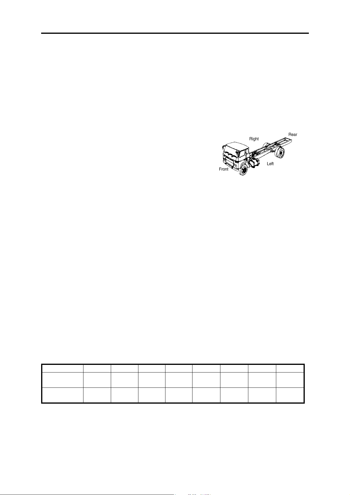
Vehicle direction
Vehhicle direction referred in the manual is marked as the right
picture.
Maintenance standard
The matching clearance or standard performance parameter of
components while assembled.
Reparation limit
It means that the component size or component clearance after
repairing must satisfy the specified repair limit;
Wear limit
It means that if a component is overworn or exceeds its wear
limit, it must be replaced;
Unit
Legal measure units are used in this manual.
Standard Tightening Torque
To assure the safety and reliability of key vehicle parts, this
manual makes specific prescriptions to the tightening torque of the
bolts and other fasteners on those parts. As for the bolts and other
fasteners not mentioned, the structures and the sizes of them have been
standardized and they should be fastened with screwing torques
prescribed in the following table.
M6 M8 M10 M12 M14 M16 M18 M20
Ordinary car-
bon steel
High-strength
alloy steel
5~8 16~23 29~42 50~70 80~110 130~170 160~200 260~320
9~12 18~26 34~48 67~95 120~170 165~220 200~250 320~400
GL-2
General Principles
Maintenance Rule
Maintenance Schedule
It's necessary for periodical inspection and maintenance of truck to prolong its service life, improve its power
performance and fuel economy, so periodical inspection and maintenance should be carefully carried out according to the following items. Then it will achieve the max economic and social benefits.
The following schedule is not only for maintenance items of 80,000km, but also for normal maintenance
items after 80,000Km.
△—maintenance mileage at running-in period (1,500~2,500km)
☆—maintenance items at running-in period
★—maintenance items at regular driving period
Note:
Customers should carry out the inspection and maintenance intervals according to the different area
condition. Properly shorten the maintenance intervals can ensure the truck to get the reasonable maintenance and
move reliability. Never prolong the intervals.
Dong Feng Cummins Diesel Engine
Maintenance Item
Clean engine assembly
Check acceleration capability and decelerability
Check exhaust status
Check the leakage of eninge lubricant
Check the cleanness and reserves of lubricant
Check the leakage of fuel
Check the leakage in cooling system
Check the damage of fan belt
Remove the deposit in fuel prefilter
Check and clean air filter element
Replace engine lubricant
Replace oil filter
Check and adjust valve clearance
Replace fule filter and oil & water seperator
Replace air filter element
Check the compression pressure in cylinder
Check the injection pressure of injector
Check injection timing
Check the injection volume of injection pump
Check the working conditions of delivery pump
Check the working conditions of thermostat
Check the working conditions of radiator
Clean the cooling system of engine
Check the working conditions of supercharger,
replace while necessary
Maintenance Mileage Interval( × 1,000km)
4 8 12 16 20 24 28 32 36 40 44 48 80
△
★★★ ★★★★★★★★★
☆★★★ ★★★★★★★★★
☆★★★ ★★★★★★★★★
☆★★★ ★★★★★★★★★
★★★ ★★★★★★★★★
☆★★★ ★★★★★★★★★
☆★★★ ★★★★★★★★★
☆★★★ ★★★★★★★★★
☆★★★ ★★★★★★★★★
☆★ ★ ★ ★ ★ ★
☆★ ★ ★ ★ ★ ★
☆★ ★ ★ ★ ★ ★
☆★★★★
★★★★
★★
★
★
★
★
★
★
★
★
★★
GL-3
Clutch
General Principles
Maintenance Item
Check the working conditions of clutch
Check the free travel of clutch pedal
Check the leakage of the hydraulic pipeline and
clutch pump
Check the air leakage of clutch booster
Check the reserve of braking fluid in oil reservoir
Replace clutch braking fluid
Propeller Shaft
Maintenance Item
Check the looseness of the linking parts of propeller
shaft
Check the looseness of spider bearing
Check the looseness of middle bearing
Check the wearing conditions of spline
Gearbox
Maintenance Item
Clean gearbox and vent plug
Check the oil reserves in gearbox
Check oil leakage of gearbox
Replace gearbox lubricant
Check the looseness of the linking parts of the control mechanism
Check the working conditions of the bearings in
gearbox
Disassemble and check gearbox
Maintenance Mileage Interval( × 1,000km)
4 8 12 16 20 24 28 32 36 40 44 48 80
△
☆★★★★★★★★★★★★
☆★★★★★★★★★★★★
☆★★★★★★★★★★★★
☆★★★★★★★★★★★★
☆★★★★★★★★★★★★
★
Maintenance Mileage Interval( × 1,000km)
4 8 12 16 20 24 28 32 36 40 44 48 80
△
☆★ ★ ★ ★
☆★
☆★
★
Maintenance Mileage Interval( × 1,000km)
4 8 12 16 20 24 28 32 36 40 44 48 80
△
☆★★★★★★★★★★★★
☆★★★★★★★★★★★★
☆★★★★★★★★★★★★
☆★★
☆★★
★
★
Suspension System
Maintenance Item
Check the leakage of shock absorber and fasten the
bolts of brackets
Clean front and rear leaf spring and shock absorber
Fasten U bolt of leaf spring when fully loaded
Check the damage and looseness of shock absorber
Check the wearing of pin sleeve of rear leaf spring,
replace while necessary
Check if shock absorber is out of service
Disassemble leaf spring, replace spring pin and pin
sleeve
Maintenance Mileage Interval( × 1,000km)
4 8 12 16 20 24 28 32 36 40 44 48 80
△
☆★★★★★★★ ★ ★ ★★★
★★★★★★★ ★ ★ ★★★
☆★ ★ ★ ★
★★★★
★
★
★
GL-4
Axle and Wheel
General Principles
Maintenance Item
Clean alxes and wheels
Check the oil leakage of final drive
Check the fastening conditions of important
bolts
Check the pressure in tyres
Check the abnormal wearing of wheels
Check lubricant reserves of final drive, clean
vent plug
Clean and adjust hub bearings
Replace the lubricant of final drive
Wheel changing
Check the working conditions of final drive and
the bearings
Disassemble and check final drive and adjust it
Make megnatic examination for axle shaft tube
Steering system
Maintenance Item
Check the oil leakage of steering gear
Clean steering gear
Check free travel and working conditions of hand
wheel
Check the fastening conditions of the ball heads of
steering cross rod and tie rod
Check fastening conditions of steering mechanism
and its brackets
Check fastening conditions of steering arm and steering knuckle arm
Check and adjust front wheel toe-in
Check front wheel alignment
Check and adjust steering gear
Disassemble and check the connectors of steering
cross rod and tie rod
Make magnetic examinations for steering knuckle
Replace the ball head pins in steering system
Check power steeering oil reserves, add while necessary
Replace power steering transmission oil
Maintenance Mileage Interval( × 1,000km)
4 8 12 16 20 24 28 32 36 40 44 48 80
△
★★★★★★★★★★★★
☆★★★ ★★★★★★★★★
☆★★★ ★★★★★
☆★★★ ★★★★★★★★★
★★★★★★★★★★★★
★★★★
★★★★
☆★★
★★★★
★
★
★
Maintenance Mileage Interval( × 1,000km)
4 8 12 16 20 24 28 32 36 40 44 48 80
△
☆★★ ★ ★ ★ ★ ★ ★ ★ ★ ★ ★
★★★★ ★ ★ ★ ★ ★ ★ ★ ★
☆★ ★ ★ ★
☆★ ★ ★ ★
☆★ ★ ★ ★
☆★ ★ ★ ★
☆★ ★ ★ ★
★
★
★
★
★
☆★★ ★ ★ ★ ★ ★ ★ ★ ★ ★ ★
★★
Braking System
Maintenance Item
Check the free travel of brake pedal
Check parking brake and its efficiency
Check the air leakage of braking pipeline
Check and adjust the clearance between brake drum and
friction disc
GL-5
Maintenance Mileage Interval( × 1,000km)
4 8 12 16 20 24 28 32 36 40 44 48 80
△
☆★★★★★★★★★★★★
☆★★★★★★★★★★★★
☆★★★★★★★★★★★★
☆★★★★★★★★★★★★★
Braking System
General Principles
Maintenance Item
Check the fastening conditions of brake back plate
Check the wearing of brake drum and shoe, replace while
necessary
Check the working conditions of air compressor
Maintenance Mileage Interval( × 1,000km)
4 8 12 16 20 24 28 32 36 40 44 48 80
△
☆★★★★
★★
★
Other
Maintenance Item
Check battery liquid reserves, add while necessry
Check the proportion of battery liquid
Check the looseness of the rivets in chassis frame
Check the efficency of locking device of tilting
mechanism
Check the looseness of linking parts of cabin
Check the looseness and damage of cross and side
members of cargo body and the linking parts
Maintenance Mileage Interval( × 1,000km)
4 8 12 16 20 24 28 32 36 40 44 48 80
△
☆★★★ ★ ★ ★ ★ ★ ★ ★ ★ ★
★★★★
★★
★★
☆★★★ ★ ★ ★ ★ ★ ★ ★ ★ ★ ★
★★
Recommended Fuel and Lubricant
The quality of fuel and lubricant can effect the performances, quality and even life of vehicles. Therefor, to
ensure normal operations of vehicles, suitable oil products should be used according to relative prescriptions.
Dong Feng Automobile Co., Ltd. prescribes the most suitable fue and lubricants for its products. The foll-
wing are the fuel and lubricants that should be used in our products.
Fuel
Qualified light diesel in accord with GB252-87 Standard should be used. Users can choose specific class of
light diesel according to the specific temperature in his region.
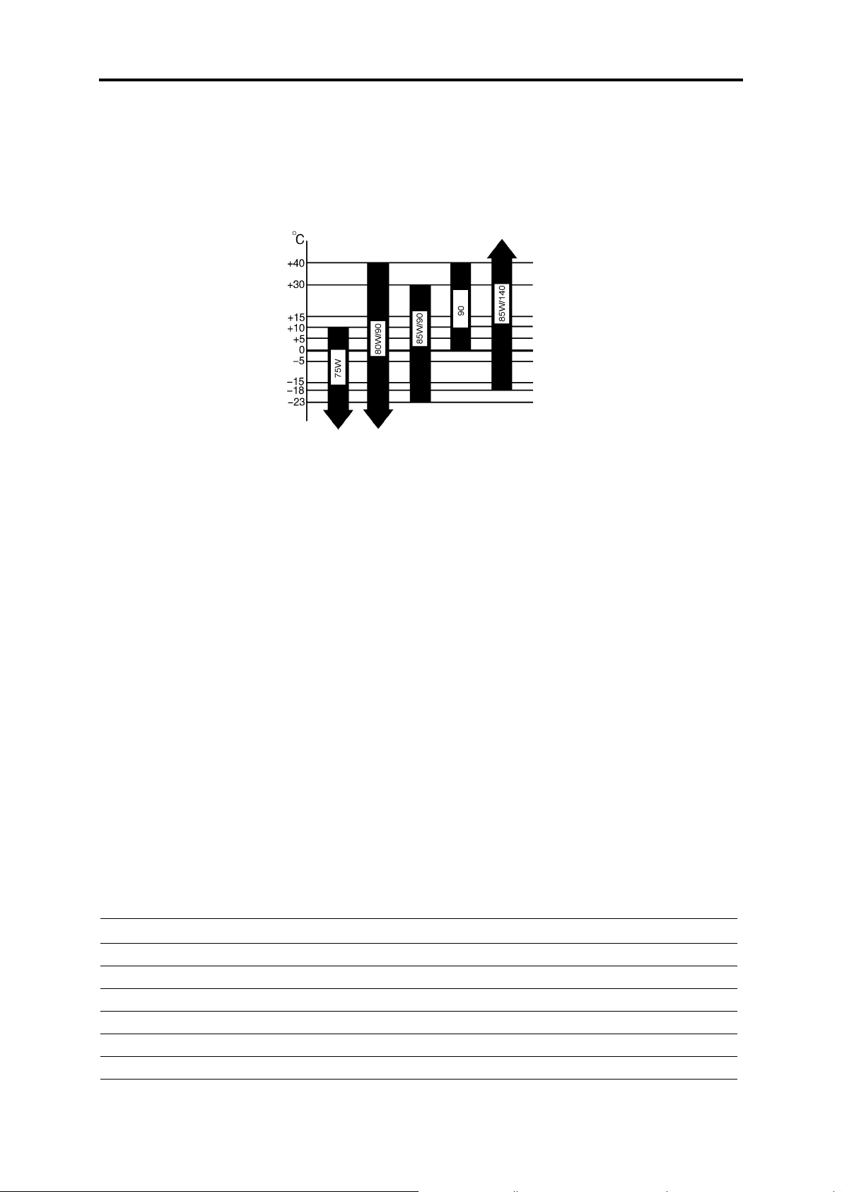
Recommended temperature scope:
Class Recommended Temperature
0# light diesel
10# light diesel
20# light diesel
35# light diesel
50# light diesel
above 4 ℃
above -5 ℃
between -5 ℃ ~ -14 ℃
between -14 ℃ ~ -29 ℃
between -29 ℃ ~ -44 ℃
Engine lubricant
High-quality lubricant meeting following standards must be used for Dong Feng Cummins engines:
Lowest standard: CF-4/SG 15W-40
Recommended Standard:CG-4/SH 15W-40
Ideal standard: CH-4/SJ 15W-40
Note:
Engine damages for using lubricants below CD15W-40 or CE15W-40 or even lower are not in our warranty
scope.
GL-6
General Principles
Suitable temperature scope:
For 15W-40: -10 ℃ ~-15 ℃; For 10W: -5 ℃ ~-20 ℃ ; For 5W-30: below -25 ℃
Lubricant for gears in driving axle
Recommend to use sulfur-phosphor API GL-5 gear lubricant for heavy duty vehicle. Applicable
environment temperatures for different classes are as follow:
Gearbox oil
Recommend to use sulfur-phosphor 85W/90 GL-4 gear lubricant for middle duty vehicle.
Lubricating grease
Recommend to use generally-used lithium grease for the lubricating points on hubs and chassis frame.
Shock absorber oil
Recommend to use specially-used shock absorber oil.
Clutch boosting liquid
Recommend to use DOT 4compounded braking liquid. Different classes of braking liquid can not be used
together.
Note:
Braking liquid made by different manufacturers can not be used together.
Engine antifreeze liquid (coolant)
Recommend to use long-term antirust & antifreeze liquid. The freeze point of the antifreeze liquid used
should be 8 ℃ lower than the minimum local temperature. Different classes of antifreeze liquid can not be used
together.
Volume Data
Part
Fuel tank 102
Engine lubrication system 9
Engine cooling system 14.5
Gearbox 4.2
Rear axle Add till the oil overflow from the inspection hole
Clutch Add to the scale of "MAX" of clutch oil reservoir
GL-7
Vo l u m e (L)
Volume Data
General Principles
Part
Power steering gear Add between the upper and lower scale of oil tank
Vo l u m e (L)
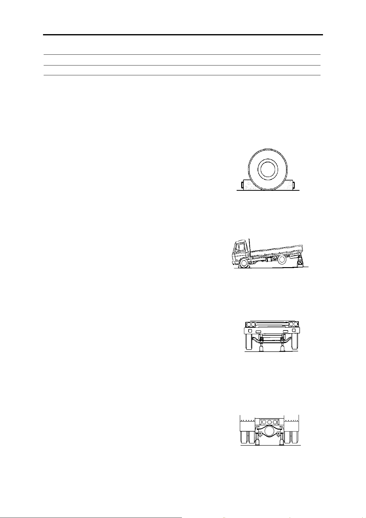
Protective Measures while Repairing
To assure safety in repairing, the following protective measures
should be taken all the way:
1) Before reparation, you should ensure that the wheels can not
turn. The measure to lock wheels is as the sketch map.
2) Ensure that the gearbox is at neutral position.
3) Ensure that the ignition switch is at "off" postion.
4) When repairing electric circuit, the negative pole should be
disconnected.
5) The jacks and brackets used should be strong enough for the
load acting on them.
Method of mounting brackets is as the sketch map.
The supporting points of front axle for mounting jacks is as the
sketch map.
The supporting points of rear axle for mounting jacks is as the
sketch map.
6) When disassemble or assemble the assemblies that have been
taken down, you should ensure that they are on a solid worktable to
avoid they would drop or turn over.
GL-8

General Principles
Cleaning
Because the parts may be covered by dirty oil and mud, cleaning is compulsive.
Applicable cleaning methods include steam cleaning, pressure cleaning, light oil cleaning, acid or alkali
cleaning, neutral medium cleaning, trichlorethylene steam cleaning, Magnus solution cleaning, etc. Part damages
may be revealed during the cleaning, so great attention should be paid while cleaning.
Metal parts
Light oil: in contrast with other solutions, light oil can't penetrate or dissolve mud. Therefore, except for
finished surface, mud should be removed by wire brush or other tools and should be cleaned in this way for two
times.
Alkali solution: if the parts are made of alloy, don't use alkali solutions for the cleaning. Instead, alkali
solutions are very effective for the cleaning of steel and cast iron.
Note:
If alkali solutions are being used, you should make some correctives such as boric acid solution. Once your
eyes or skin touch the alkali solution, you should use the corrective to clean.
Rubber parts
Don't use mineral oil for the cleaning. Use alcohol or clean cloth to remove the mud.
Oil duct
Make a metal wire to get through the oil duct to ensure it is not jammed. Wash the oil duct with cleaning
solution with high-pressure nozzle.
Antirust
After removing the oil grease on the parts, clean grease should be applied to prevent the rusting of the parts.
General Inspection
Check parts and components with special gauges or tools. Decide whether a component can continue to
serve according to specified maintenance standards. Damaged components should be repaired or replaced as
required. If one of a pair of components fitted together is worn so much that the fit clearance exceeds the specified
range, replace the pair of components together.
Out of consideration of preventive maintenance, some components should be replaced before them reaching
service limit.
Carefully inspect the surface of components by outlook or red check method. Repair or replace the component if its surface has the following abnormal signs: uneven wear, biased wear, scratch, crack, distortion, malfunction or becoming weak (spring), bended, loose, abnormal noise (bearing), distortion, malfunction or becoming
weak (spring), bended, loose, abnormal noise (bearing), discolored, seized, eroded, deteriorate (friction lining),
etc.
All the rubber pieces, such as O-rings, oil seals and washers cannot be further used after disassembled.
GL-9
General Principles
Trouble Analysis
In a vehicle, a part is made up of many components. Some parts like clutch, transmission and rear axle are
interactive functioning. Therefore, in order to find and examine trouble exactly, it is necessary to know the structure of each part as well as the functional connection between various parts.
To resolve a problem of the vehicle, you must first know the nature of the trouble. To achieve this, you must
get some exact knowledge of the trouble from the customer, including the parts that effect using conditions and
the date of the happening of the trouble.
A trouble may be caused by one or many reasons in most cases. Therefore, to examine and repair requires
the ability of systematic thinking and resolving problems step by step. For example, when the steering wheel turns
unstable, you should first examine the connection mechanism of the pitman arm instead of disassembling the
steering gear rashly, then decide whether the trouble belongs to the steering gear or to the connection mechanism.
When disassembling the part to find the cause of the trouble, proceed systematically and start from easy
problem.
It is a very important way to find out the cause of the trouble according to the manifestation of the trouble
such as abnormal noise, vibration and failure. Listed below are some common trouble signs and their reasons. As
for the detailed trouble analysis, please refer to chapter of each assembly.
1. During starting of the engine (neutral position)
Engine can
not start
Listen to the sound of the gear of the
gear of the starter Folo-tru drive
No sound Trouble in starting system
Having sound Engine troubled
2. After engine started
Abnormal sound Engage a gear Sound does not stop Clutch cover troubled
Engine troubled
Exhaust system troubled
Sound stops Clutch driven disc troubled
Transmission troubled
3. During starting of vehicle
Abnormal sound Clutch troubled
Transmission troubled
Propeller shaft troubled
Rear axle troubled
Engine drive belt slipped
GL-10
General Principles
Unstable running of vehicle Engine troubled
Incomplete release of parking brake
Incomplete release of brake
Bumpy running of vehicle Clutch troubled
4. During vehicle running
Poor acceleration Clutch slipped
Incomplete release of brake
Incomplete release of parking brake
Engine fuel system troubled
Overload of propeller shaft
Engine rubber mounting failed
Abnormal noise Continuous noise Transmission troubled (oil insufficient or deteriorate)
Reductor gear troubled (oil insufficient or deteriorate)
Wheel hub bearing troubled (grease insufficient or
improper)
Over-low tyre pressure
Noise Transmission troubled
Reductor gear troubled
Propeller troubled
Noise when run on road bend Differential gear troubled
Noise when brake Brake troubled
Too heavy vibration Front and rear leaf spring troubled
Shock absorber troubled
Propeller shaft troubled
Engine troubled
Uneven wear of tyre or imbalance of tyres
Engine mounting troubled
Cab mounting troubled
Unstable running (straight) Incorrect front wheel alignment
Front axle troubled
Suspension spring troubled
Steering system troubled
incomplete release of brake
Uneven tyre pressure
GL-11

General Principles
Abnormal steering operation Heavy steering Steering system troubled
Incorrect front wheel alignment
Front axle troubled
Over low pressure of front wheel
Turning wheels not return Steering system troubled
Incorrect front wheel alignment
Front axle troubled
Insufficient steering angle Steering system troubled
Front axle troubled
Abnormal gear shift Difficult gear shift Abnormal clutch disengagement
Transmission troubled
Transmission handling mechanism troubled
Gear disengaged Transmission troubled
Transmission handling mechanism troubled
Abnormal braking operation Weak braking Brake system troubled
Overwear of tyres
Hub bearing clearance too large
Brake can't be released completely Brake system troubled
Hub bearing clearance too large
GL-12

Clutch
CL
Table of Contents
Main Parameter............................................................................................... CL-1
Trouble Analysis............................................................................................. CL-2
Clutch Mechanical System ............................................................................. CL-3
Adjustment of Clutch Pedal............................................................................ CL-4
Clutch Cover and Flywheel ............................................................................ CL-6
Usage and Maintenance.................................................................................. CL-7
Clutch
Clutch
Main Parameter
Distributing diameter (mm)
Bolt install hole size
Positioning pin hole size
Angle between positioning hole and installing bolt hole
Friction lining size D×d
Working pressure force 10250
Release bearing stroke (mm) 10
Pressure plate lift range (mm)
Height of release finger (mm) 56±1
Unbalance static of the cover assembly (g.cm)
Unbalance static of the driven disc assembly (g.cm)
Torque (N.m) Max=770
Note:
The DOT4 compound brake fluid is recommended to the clutch.
Unclean or dirty brake fluid is forbidden to use.
Do not splash the brake fluid down to the paint. (It may erode the paint.)
You must make use of the tools to disassemble and assemble the clutch pipeline system.
Make use of the clean brake fluid to clean the master cylinder, booster and the fluid reservior.
The mining oil such as gasoline, kerosene, etc, it will erode the rubber parts in the hydraulic pressure system.
After clean the clutch pressure plate, dry it with the suction cleaner, not the compression air.
Aperture (mm)
Number of holes 8 (4 pairs)
Distributing diameter (mm)
Aperture (mm)
Number of holes 2
Φ 368.3
Φ 10.3 (+0.25)
Φ 363.53
Φ 7.92 (0.03)
Φ 9.52 (+0.03)
15°
Φ 325× Φ 200
≥ 1.4
≤ 50
≤ 25
CL-1

Trouble Cause Method
Clutch disengaged incomplete or vehicle started
unstably
Clutch slipped
Abnormal sound of clutch
Clutch pedal can't be
stepped down
Changes in clutch pedal
Too large clutch pedal
force
Clutch
Trouble Analysis
Clutch pressure plate or driven disc lining distorted or cracked
Release lever improper adjusted
Air in clutch hydraulic pressure controlling system pipe
Too large clutch pedal free travel
Clutch master cylinder or booster
worked abnormally
Clutchdriven disc friction lining or
pressure plate worn
Oil stain on clutch driven disc or
pressure plate
Too small clutch pedal free travel
Clutch booster push rod has no free
stroke.
Clutch booster push rod can't return.
Clutch pressure plate spring failed
Clutch release bearing worn
Clutch booster push rod adjusted
improperly
Clutch release bearing worn or
improper lubricated
Clutch pressure plate or driven disc distorted
Transmission input shaft or driven disc
spline worn
Clutch pedal shaft bush worn
Clutch out of control
Cylinder of clutch hydraulic pressure
system blocked
Release lever worn
Air in hydraulic pressure pipeline
Master cylinder oil pipeline blocked
Clutch booster troubled
Release shaft bushing blocked or
improper lubricated
Release bearing flange blocked
Release lever bush improper lubricated
Change the pressure plate or driven disc
lining
Disassemble and repair
Exhaust the air in the pipe
Readjust accord to the standard
Disassemble and repair
Replace driven disc friction lining or
pressure plate
Clean driven disc friction lining and
pressure plate
Disassemble and repair
Readjust accord to the standard
Check master cylinder push rod and
booster oil seal
Change the pressure platespring
Replace the release bearing
Disassemble and repair
Replace the release bearing release bearing
Change the pressure plate or driven disc
Replace input shaft or driven disc
Replace the bushing
Adjust
Adjust
Replace
Exhaust air in the pipe
Clean or replace
Disassemble, repair and clean
Replace bush or lubricate
Correct or replace the bearing flange
Lubricate
CL-2
Clutch
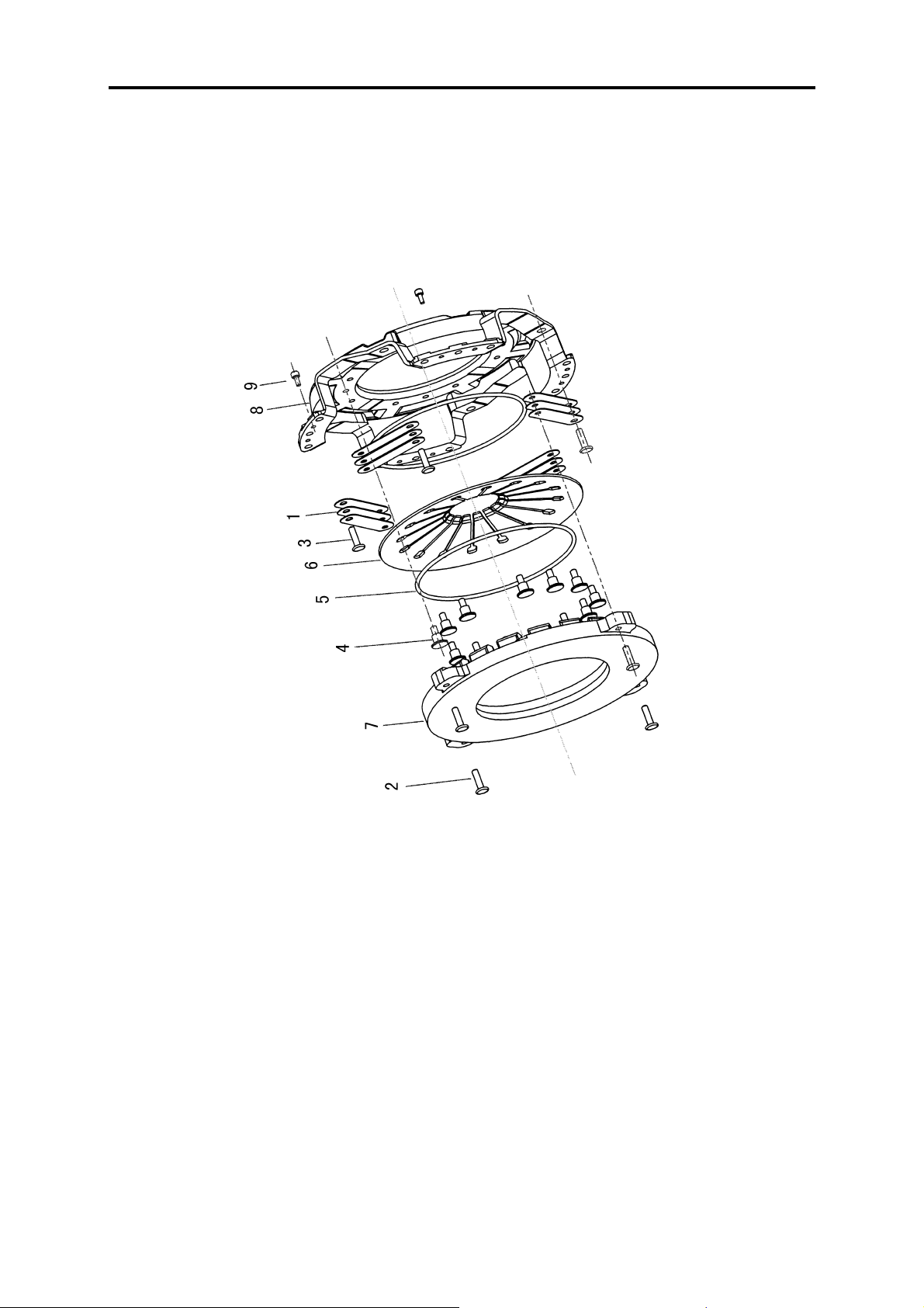
Clutch Mechanical System
1.Clutch pedal bracket assy
2.Lower fixed plate--pedal bracket
3.Hose assy--oil reservior to master cylinder
4.Clutch pedal welding assy
5.Pedal sleeve
6.Clutch pedal shaft
7.Clutch pedal return spring
8.Bush--pedal assy
9.Pin
10.Clutch master cylinder assy
11.Oil reservior assy
12.Front oil pipe assy
13.Free flowing coupling
14.Front hose assy--clutch
15.Rear oil pipe assy--clutch master cylinder to
booster
16.Clutch rear oil pipe bracket
17.Rear hose assy
18. Booster assy
19.Nylon pipe assy (air pipe to four-way protective
valve)
20.Bracket set--clutch booster
CL-3
Clutch
Adjustment of Clutch Pedal
1.Adjust the height of the clutch pedal by adjusting the pedal setting bolt. The height of clutch pedal is about
160~170mm.
2.Adjust the free stroke of the clutch pedal.
Release bearing
Check the release bearing for any crack or wear. The release bearing must be smooth and turn without noise.
Replace it if necessary.
Check the release sleeve and release fork for wear, damage or erode, and replace if necessary.
Bearing lubricating
Make use of the recommended lubricant for the connecting surface and the attrition surface of bearing and
fork.
Note:
Overmuch lubricant may cause clutch driven disc damaged.
Clutch driven disc and pressure plate
Clutch driven disc
1.Friction lining rivet
2.Friction lining
3.Wave spacer
4.Front damping disc
5.Wave spacer rivet
6.Damping spring
7.Damping spacer
8.Disc hub
9.Damping impact spacer
10.Damping spring spacer
11.Limiting pin
12.Rear damping disc
CL-4
Clutch
Check
Check the degree of wear of the driven disc surface.
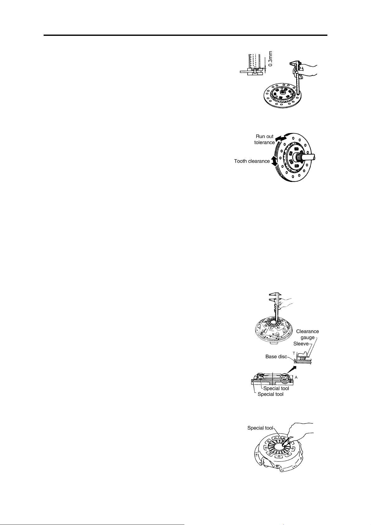
Wear limit:(from friction surface to the rivet head) 0.3mm.
Check the spline tooth clearance and the run out tolerance of driven
disc.
Check the driven disc for ablation, color changed, or contaminated
by oil or grease. Replace if necessary.
Installation
Smear some grease on the connecting surface and the spring.
Overmuch grease may damage the surface of the driven disc.
Clutch pressure plate
Check and adjust
Check the height and plainness of the diaphragm.
When checking the height of the diaphragm, set a clearance
gauge(T=0.2mm) on the distance bushing.
Height of the diaphragm: 41~43mm (base disc to the top of the diaphragm)
If the height is not in the range of the specific range, you need to
replace the pressure plate.
Shake the pressure plate gently, listening and check the wear or damage of the diaphragm supporting ring. Or you can knock the rivet head
gently to find if there is cracks. Replace the pressure plate if necessary.
Check the surface of the pressure plate for any ablation or dirt, make
use of the corundum paper to get rid of them if necessary.
Check the connecting side of the pressure plate and the driven disc for
any distorsion or damage, and replace them if necessary.
Adjust the plainness of the diaphragm by tools.
Plainness: <0.7mm
When install the clutch pressure plate and driven disc, insert the special tool into the clutch driven disc spline(used to align and orient).
Screw down the fixing bolt of the clutch cover.
Screw down the bolt in an acrossed sequence, following two steps.
CL-5
Clutch
Clutch Cover and Flywheel
1.Driving blade
2.Rivet--pressure plate
3.Rivet--cover
4.Rivet--supporting ring
5.Supporting ring
6.Diaphragm spring
7.Pressure plate
8.Clutch cover
9.Balancing rivet
CL-6
Clutch
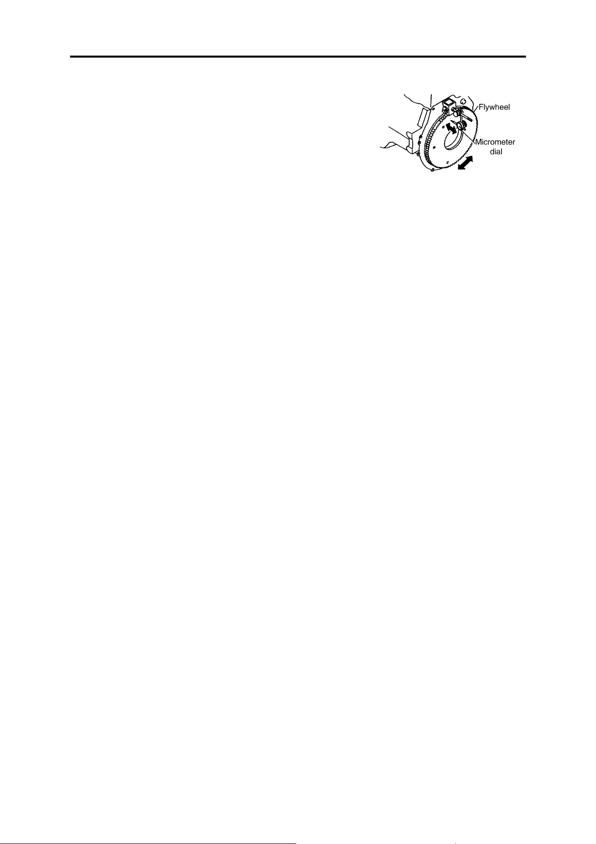
Flywheel check
Check the working face of the flywheel for ablation or color changed,
make use of the corundum paper to get rid of them if necessary.
Check the plainness of the flywheel surface: <0.1mm
Usage and Maintenance
The diaphragm clutch which has two positioning holes and been connected by 8 M10 bolts, is made up by cover assy and driven disc assy.
The drive blade is used to transmit the engine torque between the
pressure plate and clutch cover. Two ends of the drive blade are riveted to
the clutch cover and the pressure plate. When disengaged, the drive blade
may have the axial deformation, and there is no friction between clutch
cover and pressure plate. Therefore, the clutch will has a higher drive efficiency, lower noise, and stable engage.
The working pressure force is caused by the diaphragm. The original
height of the clutch release finger is 56±1mm. During the usage, it will be
heigher because of wearing. The wear limit of the two pieces of the
friction lining is 2×1.8mm. During the wearing time, the distance between
the toppest point of the release finger and the release bearing end has to be
adjusted to 3~4mm, and the largest release stroke of the release finger is
10mm.
The outside diameter of the driven disc friction lining isΦ325mm. Its
material may adopt to asbestos or non-asbestos according to the need of
the customer. The original thickness of the driven disc working surface is
9.7±0.3mm. The assembly is equipped with big and small shock-absorber
spring and damping spacer which is good to absorb the impact and
vibration from the chassis.
The involute spline is used to connect the driven disc and
transmission.
The working surface of the driven disc can't be stained with oil soil
during the assembling and storage.
When the friction lining is in trouble, such as the rivet loose or come
out or cracked, the driven disc must be replaced immediately.
During the assembling and instorage, the working surface of the
clutch cover assembly must haven't any scuffing and rust. If the release
finger is broken or the pressure plate reached to its wear limit and the
diaphragm is broken, you must replace the assembly immediately.
CL-7

Clutch
CL-8

Transmission
MT
Table of Contents
Maintenance Standard ................................................................................... MT-1
Transmission Dismount................................................................................. MT-2
Transmission Disassembly ............................................................................ MT-3
Cleaning....................................................................................................... MT-20
Check ........................................................................................................... MT-20
Reassembly.................................................................................................. MT-24
Transmission Mount .................................................................................... MT-37
Maintenance Standard
Transmission
Maintenance Standard
Item
Clearance
between gear
shift lever and
select lever
Radial clearance between gear shift lever and
its spline
Clearance
between gear
Transmission top cover
shift lever and
guide block
Clearance between gear shift fork and slide
sleeve
Gear shift fork
shaft self-
upper cover
Transmission
locked spring
Backlash between mainshaft and countershaft
Axial clearance of the 2nd gear
Axial clearance of the reverse gear
Radial clearance between mainshaft spline
hub and mainshaft
Radial clearance between slide sleeve and
coupling gear
Transmission body
Axial clearance of ball bearing
Lockpin type
Slide block
type
Synchronizer
Gear shift lever
Gear select lever
Gear shift lever
Each guide block
Free length
Pressure force
Pretravel of synchronizer
conical ring and conical disc
Clearance between baulk
ring and synchronizer conical ring
Radial clearance between
baulk ring and fixed tooth
seat
Axial clearance between
fixed seat and synchronizer
closing ring
Axial clearance between
fixed seat and synchronizer
backing block
Free length of the backing
block spring
Packing force of the backing block spring
Nominal
Dimension
(mm)
-
-
-
-
-
-
-
-
-
-
-
-
-
---
-
-
-
-
-
15
-
Sevice
Standard
(mm)
0.1~0.4
0.05~0.11
0.1~0.4
0.10~0.29
34.0~36.0
140~190
N
0.15~0.25
0.3~0.5
0.3~0.6
0.2~0.3
0.45~0.55
0~0.5
1.5~2.5
5.3~5.7
> 0.5
0.05~0.35
---
6~10N
Repair
Limit
(mm)
-
-
-
-
--
-
—
-
-
-
-
-
-
--
--
--
-
Wear
Limit
(mm)
0.8
0.5
1.0
1.0
110N
0.5
0.7
1.0
0.5
1.0
0.5
2.0
0
4N
Remark
When press to
25mm
When press to
12.5mm
MT-1
Tightening Torque
Transmission
Item
Clutch housing connecting bolt 142~186
fasten nut of propeller shaft connecting flange 333~549
Transmission upper cover fixed bolt and nut 32~42
Transmission cover fasten bolt 20~26
Reversing lamp switch and neutral position switch 20
Power take-off housing connecting bolt Standard 47~63
Countershaft rear bearing cover fixed bolt 59~79
Fixed bolt of mainshaft rear bearing seat
Fixed bolt of drive gear shaft bearing cover 33~44
Reverse gear shaft locking plate bolt 20~26
Mainshaft front locking nut 300
Oil drain screw plug and filler port screw plug 120~140
Gear shift guide bolt 40
Countershaft rear locking nut 300
M12 59~79
M14 93~124
Tightening Torque (N.m)
Transmission Dismount
Before disassemble the assembly, switch the ignition key to OFF, and wedge up the front and rear wheel to
ensure the safety.
1.Screw off the drain plug screw, drain off the lubricant oil from the underpart of the transmission;
2.Disassemble the driving shaft assembly and central support bearing;
3.Remove the speedometer flexible shaft;
4.Disassemble transmission control system
5.Remove the return spring and dowel pin of the clutch slave cylinder then safely put the clutch slave cylinder
assembly onto the frame;
6.Remove wire and tube.
7.Disassemble the transmission with transmission jack and steel wire.
MT-2
Transmission
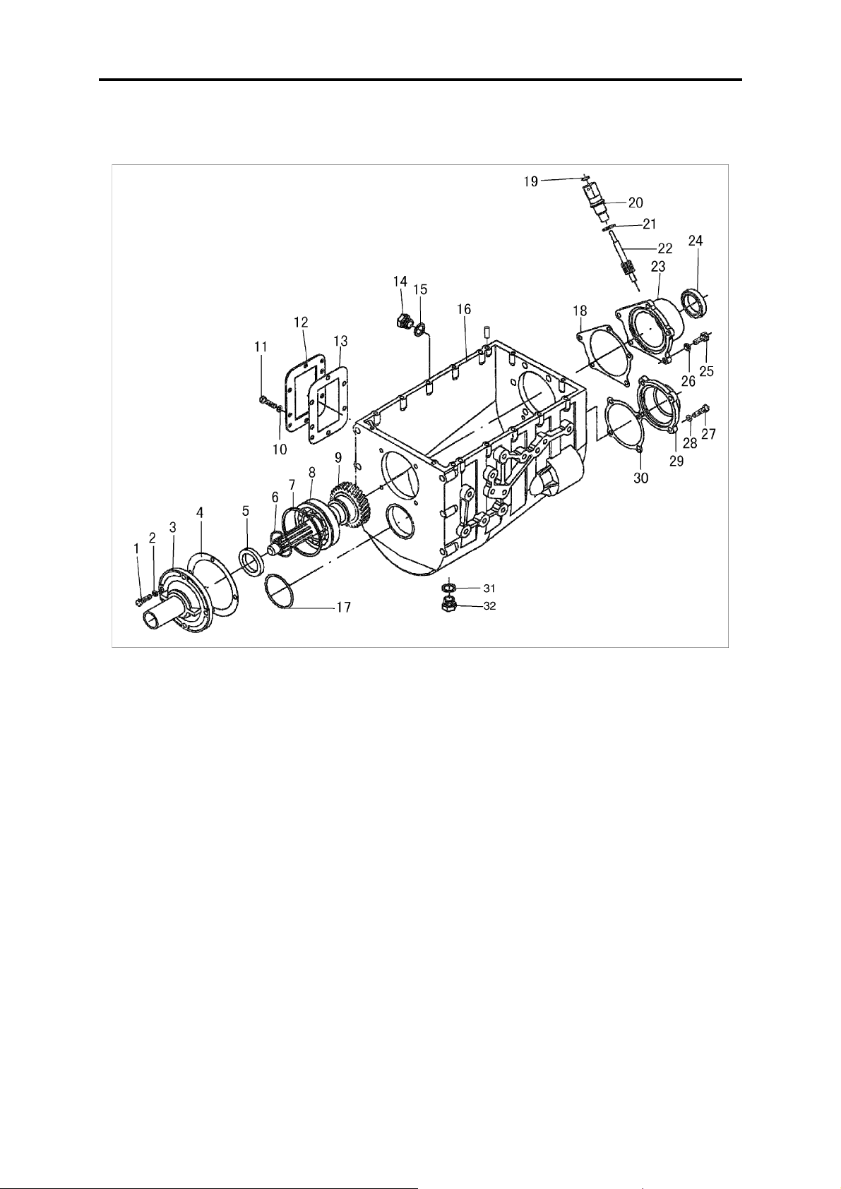
Transmission Disassembly
Transmission housing and drive gear shaft
1.Small hex guide bolt
2.Spring washer
3.Bearing cover--drive gear shaft
4.Bearing cover spacer--drive
gear shaft
5.Oil seal --transmission drive
gear shaft
6.Snap ring for shaft
7.Staved steel ring for shaft
8.Rear bearing--transmission
drive gear shaft
9.Transmission drive gear shaft
10.Spring washer
11.Hex bolt
Set the transmission on the working table carefully. If there is not a working table, make use of a simple table
to support the transmission housing first, and then carefully do the disassembly.
12.Cover board--power take-off
hole
13.Cover board spacer--power
take-off hole
14.Oil screw plug assy
15.Sealing washer
16.Transmission housing
17.O-ring--transmission countershaft
18.Rear bearing seat spacer-mainshaft
19.Speedometer oil seal assy
20.Speedometer flexible joint
21.Sealing washer
22.Speedometer driven gear
23.Rear bearing seat--mainshaft
24.Skeleton oil seal assy
25.Small hex guide bolt
26.Spring washer
27.Bolt--for bearing cover
28.Spring washer
29.Countershaft rear bearing
cover
30.Spacer--countershaft rear bearing cover
31.Sealing washer
32.Oil screw plug assy
MT-3
Transmission
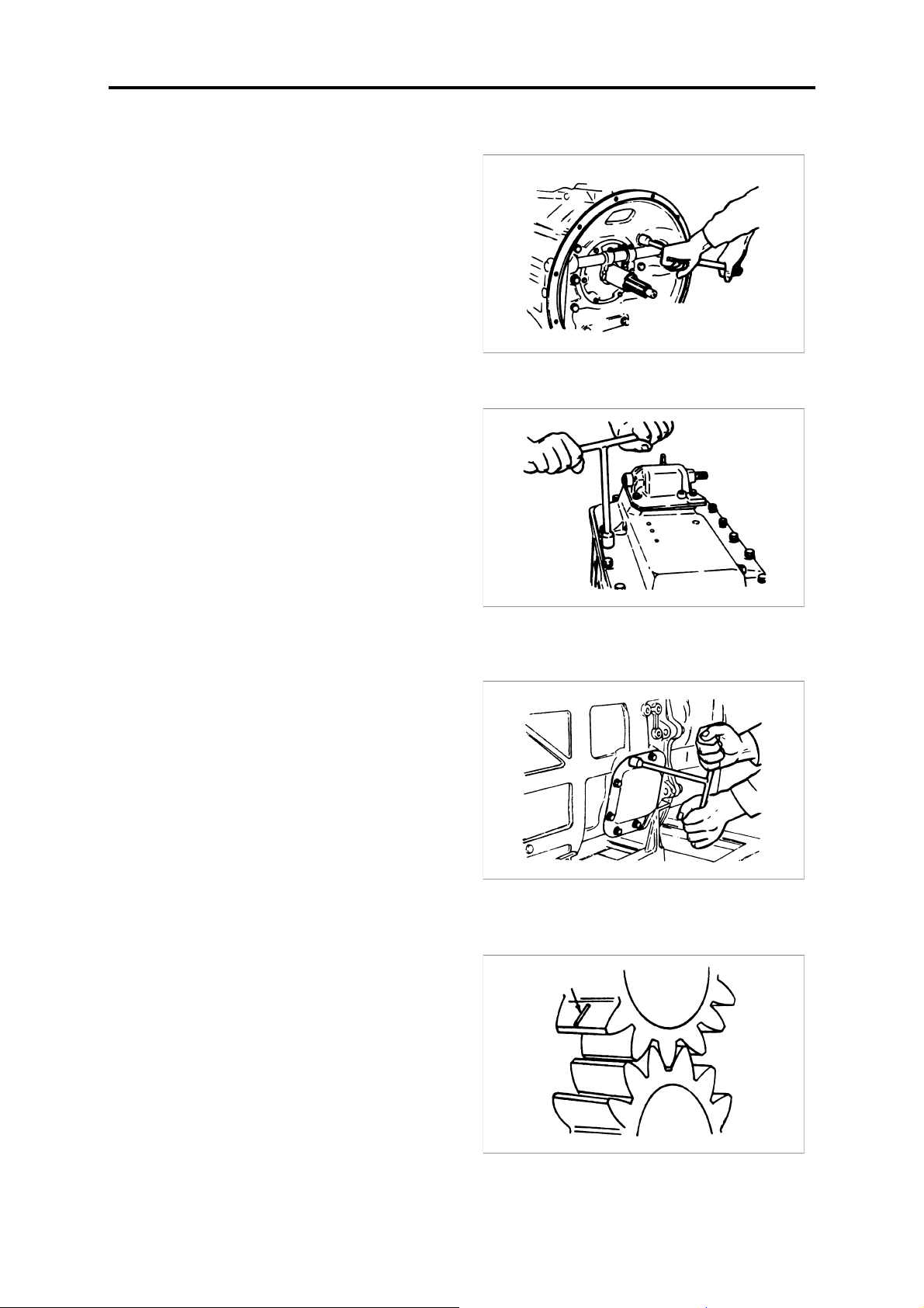
Disassembly of transmission accessories
1.Remove the clutch housing assembly;
2.Remove the transmission upper cover assembly and
spacer;
3.Dismantle the power take-off cover and spacer;
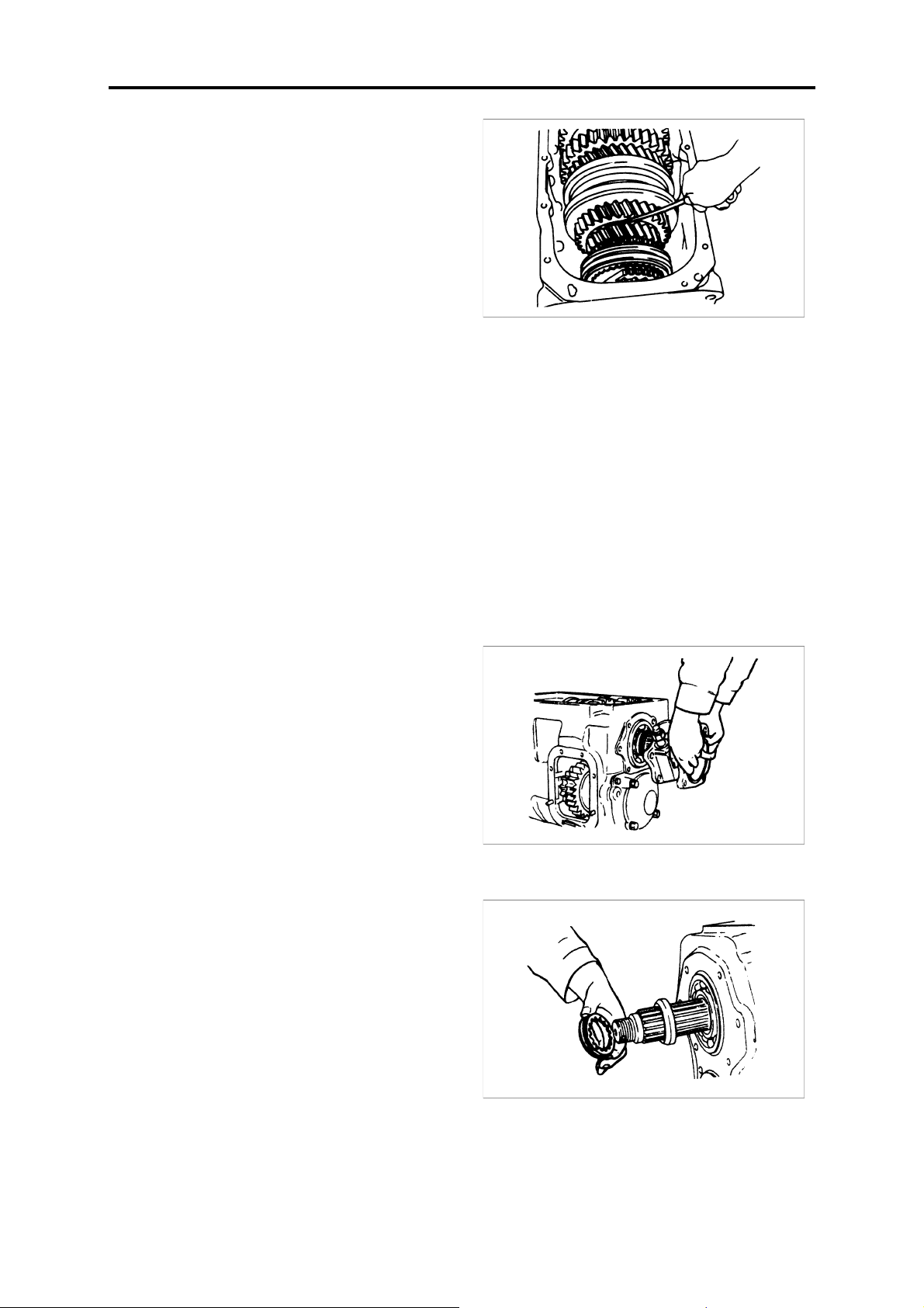
4.Measure the backlash of every pair of gear and take the records;
Note: Take three points of every pair of gear to measure.
MT-4
Transmission
5.Measure the axial clearance of every gear and take the
records.
Check point
1.Clearance between 6th speed gear and 6th speed gear thrust ring;
2.Clearance between 4th speed gear and 6th speed gear thrust ring;
3.Clearance between 3rd speed gear and 3rd and 4th speed gear fixed seat;
4.Clearance between reverse gear and reverse gear fixed seat;
5.Clearance between 2nd speed gear and 3rd speed gear thrust ring;
6.Clearance between 1st speed gear and reverse gear seat.
Transmission body
1.Remove the rear bearing cover of the mainshaft;
2.Remove the speedometer drive gear and spacer;
MT-5
 Loading...