

Page 1
Operating and Maintenance Handbook
Libretto Is truzioni Uso e Man utenzione
Bedien ungs- und Wa rtungsanleitung
Bedienings- en onderhoudshandleiding
Livret d'Usage et d'Entretien
Man ual de ins trucciones de uso y mantenimiento
Read all instructions and advice given in this handbook carefully before use.
Prima di utilizzare il generatore leggere attentamente le istruzioni e le indicazioni riportate nel seguente manuale.
Vor dem Gebrauch des Generators diese Bedienungu- und Wartungsanleitung aufmerksam lesen.
L
ees alle aanwijzingen en adviezen in deze handleiding nauwkeurig door voordat u de generator in gebruik neemt.
Avant d’utiliser le genérateur lireattentivement les instructio
ns et les renseignements du preésent livret.
Antes de utilizar el generador leer con cuidado las instrucciones y las indicaciones del manual.
T2500 H/HG-LP
T4000 H/HG-LP
T5500 H/HG-LP
GENERATOR DOMETIC
Page 2
�
�
�
�
�
��� ���
��� ���
��� ���
��� ���
��� ���
��� ���
��� ���
��� ���
� �
� �
�����
�����
����
� �� ��
�
�
� �
�
�
�
� �
�
�
� �
� �
�
�
�
� �
� �
� �
� �
� �
�
� �
�
� � �
�
� �
� �
� �
� �
� �
�
�
�
�
�
�
�
�
�
�
�
� � � �
� �
�
� �
�
�
�
�
�
Page 3

1
©
All rights reserved
Printed in Italy
Text and graphics by: VEGA Forlì
No part of this publication may be reproduced, copied or transmitted in any form or by any means without prior written permission from
DO
METIC ITALY spa.
Figures, descriptions, reference and technical data in this manual are given as mere example and are not binding.
Because of policy of contin
ual product and safety improvement, we reserve the right to make changes at any time
without notice.
DOMETIC ITALY
SPA
GENERAL INDEX
................................................ Pag. 1÷9
................................................ Pag. 10÷18
................................................ Pag. 19÷27
................................................ Pag. 28÷36
................................................ Pag. 37÷45
................................................ Pag. 46÷54
I
D
NL
INDEX
Description Page
1.0 Identification ..................................................
2
1.1 Manufacturer ..................................................... 2
1.2 Definitions .......................................................... 2
1.3 Transport Handling storage ........................... 2
1.3.1 Storage conditions ............................................. 2
1.3.2 Weight ............................................................... 2
1.3.3 Overall dimensions ............................................. 2
1.3.4 Handling ............................................................ 2
2.0 Installation ......................................................
2
2.1 Authorised personnel ......................................... 2
2.2 Mounting the generator ...................................... 3
2.3 Electrical connections ........................................ 3
2.3.1 Connection of the battery recharger ................... 3
2.3.2 Connection of the starter battery ........................3
2.3.3 Connection of the remote control panel ............. 3
2.4 Installing the fuel tank ......................................... 3
Connection to gas canister ................................ 3
3.0 General operation .........................................
4
3.1 Description of generator and functioning ............ 4
3.2 Safety advice ..................................................... 4
3.3 Noise levels ........................................................ 4
4.0 Instructions for use ......................................
5
4.1 Starting the generator ........................................ 5
4.2 Stopping the generator ...................................... 5
4.3 Inherent risks ..................................................... 5
4.4 Improper use ..................................................... 5
4.5 Useful advices.................................................... 5
4.6 Troubleshooting ................................................. 5
5.0 Maintenance operations ..............................
6
5.1 Nature and frequency of checks ........................ 6
5.2 Maintenance operations which do not
require qualified technicians ............................... 6
5.3 Maintenance operations which require
qualified technicians ........................................... 6
5.3.1 Oil change ......................................................... 7
5.3.2 Air filter maintenance .......................................... 7
5.3.3 Spark plug maintenance .................................... 7
5.3.4 Regulating the voltage ........................................ 8
6.0 Inactivity and dismantling ...........................
8
6.1 Dismantling ........................................................ 8
7.0 Dealing with fire hazards .............................
8
8.0 Technical data sheet ....................................
9
8.1 Technical specifications ..................................... 9
8.2 Wiring diagrams .........................................55÷69
GB
F
SP
Dometic Italy spa
Page 4
1.0 IDENTIFICATION
The identification plate of the machine is affixed outside
the plate casing (see fig. 1).
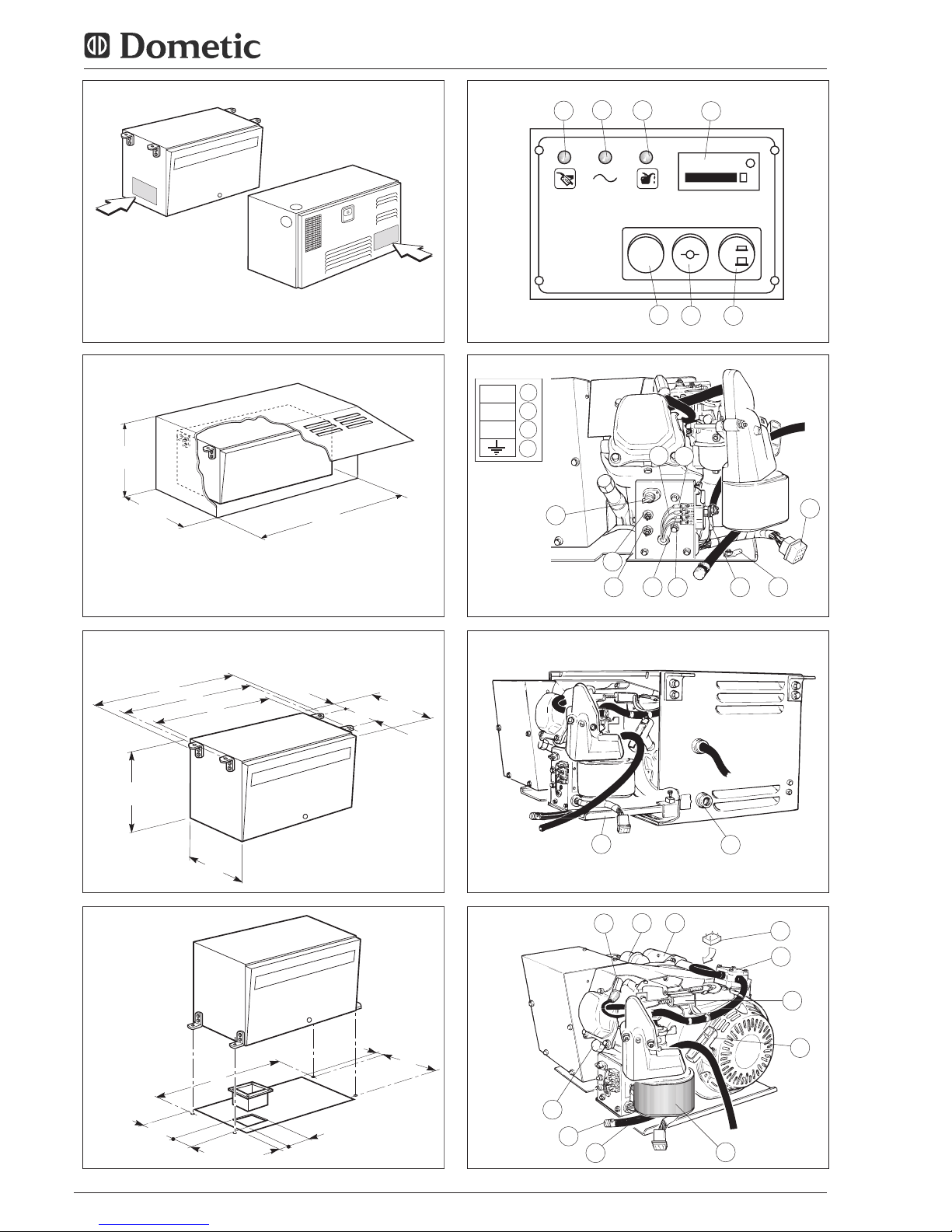
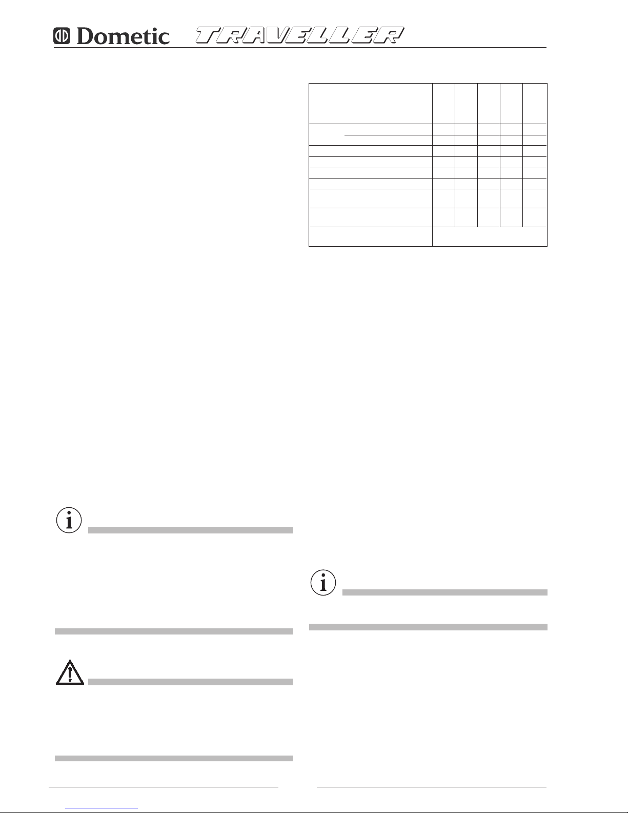
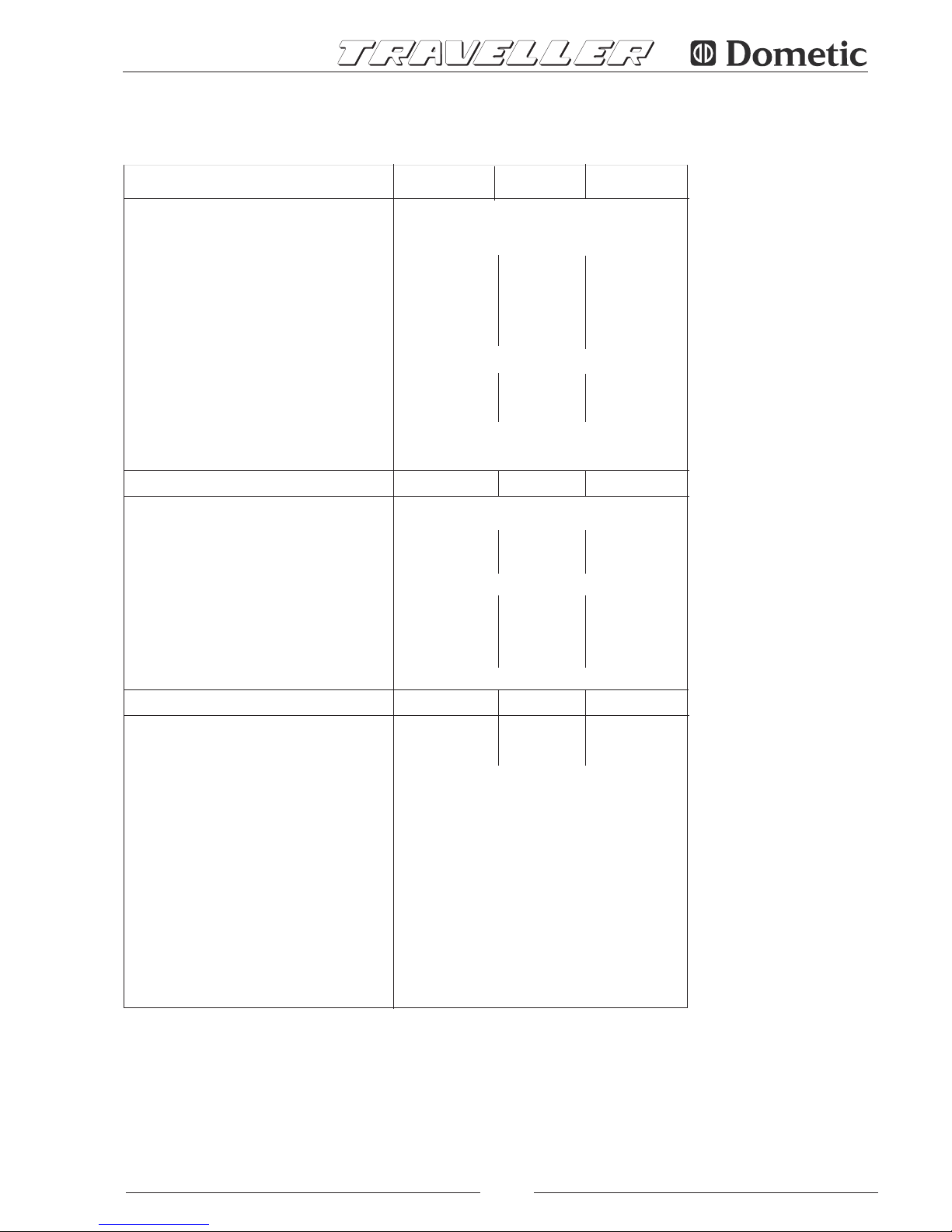
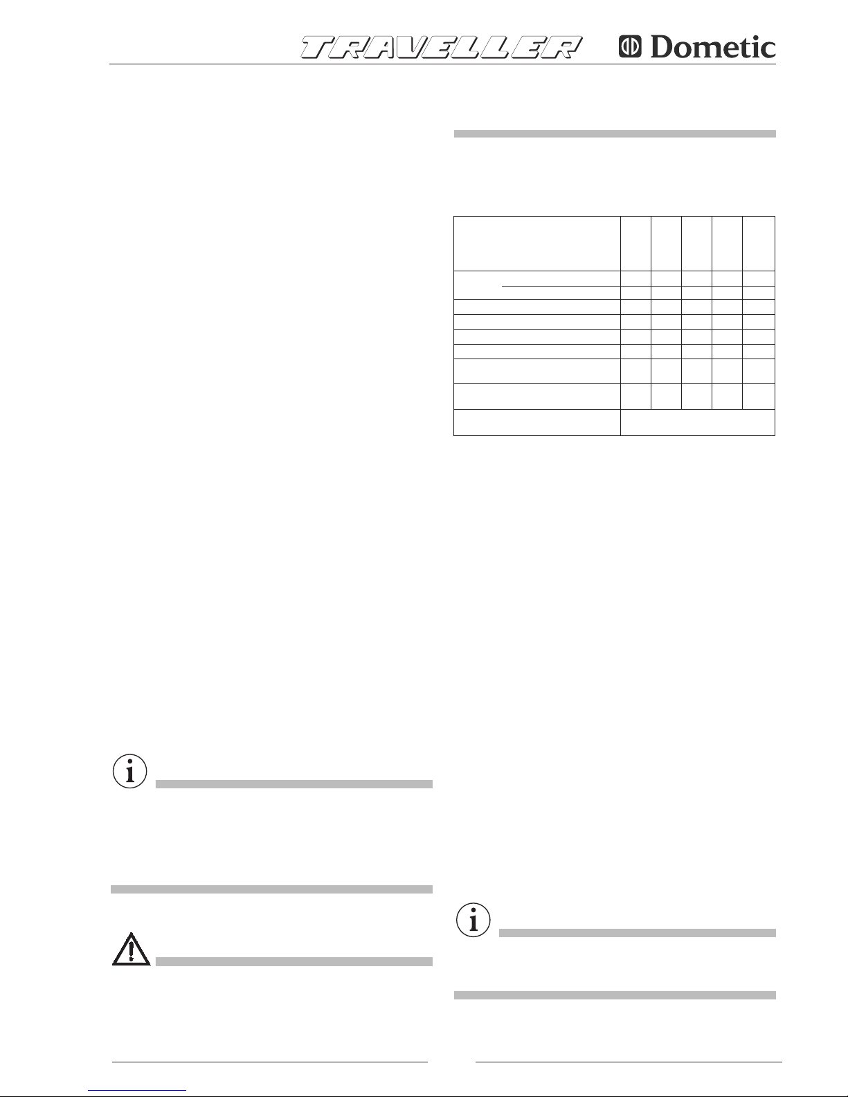
1.3.3 OVERALL DIMENSIONS
See figg. 2, 3, 4 :
Model
1.1 MANUFACTURER
DOMETIC ITALY spa
Via Virgilio, 3
47122 FORLI' ITALY
P. IVA 00718330400
1.2 DEFINITIONS
In this handbook, three types of “safety graphics” are used
to point out different levels of danger or any other important
information:
DANGER
Draws attention to potentially dangerous situations which
may cause serious personal injury.
CAUTION
Draws attention to potentially dangerous situations which
may cause personal injury or material damage.
IMPORTANT
Dr aws attention to s ituations which m ay cause
malfunctioning or damage to the machine.
2500 4000 5500
mm 470 660 700
A
NOITALLATSNI "A" EPYTNOITALLATSNI "B" EPYT
B
mm 535 740
C
mm 565 770
mm 320 475 515
D
E
mm 315 355 510
F
mm 260 310
mm 27 62
G
H mm
I
mm 65 78
L mm 65 265
M mm 225 130
mm 36 17
N
O mm 535 740 735
P
mm 27 62 55
Q mm 260 310 370
.MID GNINEPO
mm 590 780 770
X
mm 385 540 505
Y
Z
mm 335 380 550
Air intake area
2
m
c
220 260
1.3 TRANSPORT - HANDLING - STORAGE
1.3.1 STORAGE CONDITIONS
The generator is protected against sudden impact by
suitable packing consisting of cardboard, polystyrene and
a wooden frame support.
The generator should be stored horizontally in a dry and
wellventilated room.
1.3.2 WEIGHT
Gross weight (including packing):
Mod. 2500 .......................................... Kg 62
Mod. 4000 .......................................... Kg 114
Mod. 5500 .......................................... Kg 140
1.3.4 HANDLING
The packed generator can be handled by normal means of
lifting and transport.
Boxes are fitted with spacers which enable the use of
manual forklifts.
DANGER
Strictly observe the accident prevention precautions and
safety regulations during lifting and transport, and always
use machines
be lifted.
2.0 INSTALLATION
2.1 AUTHORISED PERSONNEL
The generator shall be installed onto the vehicle (caravan,
motorhome or special vehicle) by authorised personnel
only, namely by skilled technicians or workshops, authorised
directly by DOMETIC ITALY
If the installation is carried out by nonauthorized technicians
2
with a higher maximum capacity than the load to
Page 5

3
DANGER
The instructions given in sections 2.2 2.3 2.4 are
addressed to qualified technicians only.
2.2 MOUNTING THE GENERATOR
Generators mod. 2500 4000 are provided
with fixing brackets,vibration dampers and petrol filter to be
placed on the fuel feed hose to the generator. Brackets
allow either suspended type "A” mounting (see fig. 3) or
traditional type "B” mounting (see fig. 4).
This is made possible by the supporting frame of the outer
casing.
Generator mod. 5500 is provided with brackets for fixing
the external seal, brackets for anchoring the unit, vibration
dampers, silencer (pos. 29 fig. 16) to be coupled to the
exhaust hose delivered as accessory AG 125 (pos. 34 fig.
16), and fuel filter which is standard installed inside the
casing (pos. 33 fig. 15). The brackets (pos. 31 fig. 16) which
allow to fix the seal (pos. 35 fig. 16) allow to mount the
generator complete with seal inside the arranged
compartment and to perfectly seal the vehicle side. The
exhaust hose can be positioned at will as shown in fig. 16
by rotating the curve inwards to either upper position or
lower position. By removing the curve, it is also possible to
directly fit the exhaust pipe by crossing the casing on its left
hand side. The prearranged floor must tolerate both the
generator mass and the vibrations due to the motion of the
vehicle ("TYPE B” mounting).
The type “A” mounting (suspended installation) offers the
following advantages: reduced overall dimensions, quick
installation, easy access for both ordinary and extraordinary
maintenance operations.
Make sure there is enough space around the generator
casing for air to pass freely (for cooling). It is also necessary
to leave at least 20 mm distance between the casing and the
surrounding parts.
If the breathing manifold is positioned behind one of the
vehicle's wheels, make sure that the tyre is prevented from
throwing
water into the casing when travelling on wet roads.
For the type “A” mounting, use the plate supports provided
to ensure that the genset is fixed securely. If type “B”
mounting is preferred (traditional installation), a watertight
compartment (fig. 2), set towards the vehicle interior and
having the dimensions given in section 1.3.3, needs to be
prearranged, with exhaust holes and air inlets drilled into the
floor and door. In addition, use an exhaust union (fig. 4),
supplied as accessory, to be fixed directly onto the generator
casing with screws or rivets. In order to prevent the exhaust
gas recycling within the compartment, place flameproof
sealing around the exhaust union.
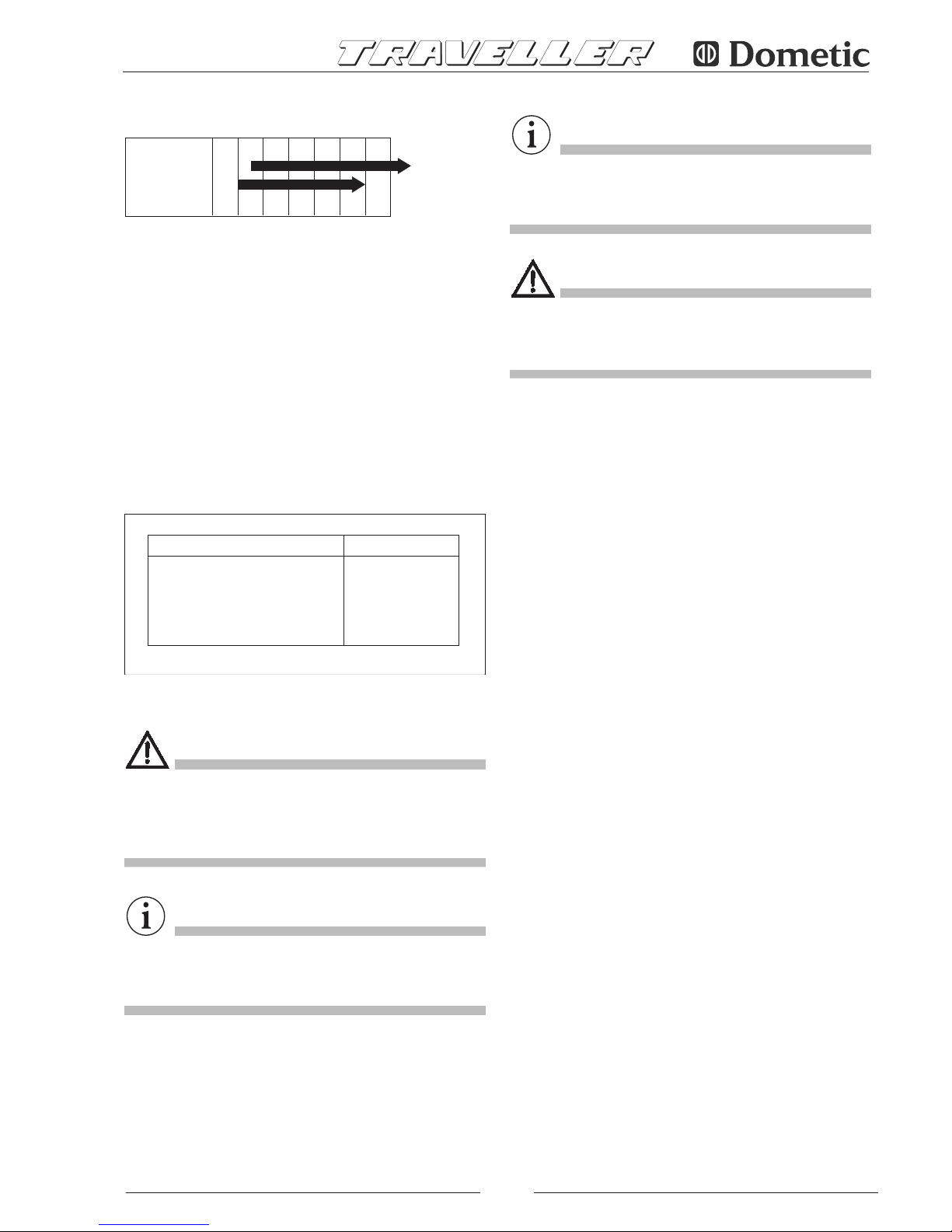
2.3 ELECTRICAL CONNECTIONS
For the 230V use a standard cable with crosssection
according to table 1 below. Pass it inside the casing via the
airlead (pos. 30 fig. 7 and 9) and connect to the terminals
(pos. 17/18 fig. 6 and 14). Connect the earth wire to pos. 15.
The electrical circuit should have a relay or changeover
switch (such as accessory AG102/AG113), so as to prevent
any damage to the generator when the camper is connected
to an external mains supply (precedence is automatically
given to the mains).
2.3.1 CONNECTION OF BATTERY
RECHARGER
Use a wire with minimum crosssection according to table
1 above to connect the terminal (pos. 16 fig. 6 and 14) to
the positive lead of the battery to be recharged.
Insert the AG111 voltage regulator, or alternatively a switch,
to interrupt recharging when complete.
(See wiring diagrams, pages 55 ÷ 71).
2.3.2 CONNECTION OF STARTER BATTERY
For starting the generator, connect the positive terminal of
the vehicle's starter battery to pos. 12 fig. 6 and 14 using a
flameresistant sheathed cable having a crosssection
according to table 1 above.
The earth cable should have the same crosssection and be
connected from pos. 13 to the vehicle chassis. Make sure
that a clean, rustfree contact is made (i.e. rub down surface
if painted), and protect with grease.
2.3.3 CONNECTION OF REMOTE CONTROL
PANEL
Fix the control panel in desired position inside the vehicle
and use the individuallytested AG103 extension cable to
connect it to the genset by means of the connector pos. 14
fig. 6 and 14.
2.4 INSTALLING THE FUEL TANK
Install the fuel tank as near as possible to the generator and
if possible on the same horizontal level, or up to 30cm
below. As well as reducing the length of fuel pipe as much
as possible, make sure it is not bent or squashed. Do not
put the tank near sources of heat, and make sure that water
Mod.
Crosssection Crosssection
6 m > 6 m
mm2230 V mm212 V
2500 2.5 2.5 10 16
4000 4 2.5 10 16
5500 4 2.5 16 25
TA B. 1
Power cables
Battery connection
Battery recharger
or workshops, Dometic Italy disclaims any responsibility
for the safety and efficient running of the generatore
accordind to the M.D. 89/392/EEC
Page 6
4
cannot infiltrate.
Use LOCTITE 577 to make all connections, so as to prevent
fuel leakages.
To connect the fuel tank to the generator, use a 6x13mm
rubbercoated tube, of the same type used for the genset
and suitable for unleaded petrol. For the extension, use the
ties and filter provided. It is advisable to use fuel hose
AG118 (accessory) for the connection from tank to refuelling
mouth.
IMPORTANT
Model 5500 does not need fuel tank, since it is standard
fitted inside the genset casing.
CONNECTION TO GAS CANISTER
CAUTION
For the LPG genset, withdraw the gas from the upright
canister and the vehicle's service regulator and from the
upper part, so that gas enters the genset at low pressure
and in the gaseous state.
(Minimum recommended pressure: 0.30 mbar)
3.0 GENERAL OPERATION
IMPORTANT
The firm disclaims any responsability for damages arising
from malfunctioning of the generator.
3.1 DESCRIPTION OF GENERATOR AND
FUNCTIONING
The generator consists of an endothermic petrol engine
connected to an alternator which produces both alternate
and direct current.
The unit comes in a soundproof casing made of pressed
steel plate and insulated with special deadening materials.
Fuel comes to the combustion engine through a pump
which is standard fitted on the unit itself.
3.2 SAFETY ADVICE
The unit is housed within a perfectly closed casing. Therefore,
there is no danger of accidental contacts with hot or moving
parts or wires under voltage.
The door of the unit is fitted with lock and key and should
not be left within the reach of children or nonauthorised
persons.
DANGER
• The unit shall be used only and exclusively with the door
closed.
• Keep inflammable substances like petrol, paints, solvents,
etc. away from the generator.
• Do not let hot parts of the genset come into contact with
inflammable materials.
• Do not fill up with the engine running if the tank is placed
close to the generator.
• Do not touch the generator or its connections with wet
hands.
• Do not replace the fuses or thermal switches with new
ones of higher amperage.
• Any check of the electrical parts shall be made with
engine stopped and by authorised technicians only.
The generator is manufactured according to the safety rules
given in the Conformity Declaration.
3.3 NOISE LEVELS
The generator has been submitted to a noise emission test
at a qualified ISTEDIL lab, where all the necessary tests were
carried out and EC Certificate No.I225/92 issued, stating
following results:
Measured according to: EC DIRECTIVE 84/536
NOISE LEVEL:
Mod. 2500 .......................................... LwA 85
Mod. 4000 .......................................... LwA 87
Mod. 5500 .......................................... LwA 87
Page 7
5
4.0 INSTRUCTIONS FOR USE
4.1 STARTING THE GENERATOR
Normally the vehicle's 12V battery is used to start the
genset.
First press the red button (pos. 27 fig. 5) on the control panel
into the “I” position.
To start the genset from cold, press and hold down the
green START button (pos. 25 fig. 5) together with the white
CHOKE button (pos. 26 fig. 5) for max. 5 seconds.
CAUTION
Do not make prolonged or repeated (more than 5 consecu
tive) attempts to start the genset, as this may damage the
starter motor.
To start the genset when already warmedup, or during the
summer, when the outside temperature is high, press the
green “START” button (pos. 25 fig. 5) only.
In an emergency the genset can be started manually using
the pullcord handle (pos. 4 fig. 8 and 15) and holding the
choke magnet (pos. 36 fig. 8 and 15) shut with one hand
if the engine is cold.
The green LED on the control panel ((pos. 23 fig. 5) indicates
that the genset is running correctly.
4.2 STOPPING THE GENERATOR
Push the red “STOP” button (pos. 27 fig. 5) on control panel
into the ”0" position. Alternatively use the safety switch on
the genset itself (pos. 7 fig. and 14) for models 2500 4000
5500.
4.3 INHERENT RISKS
DANGER
The generator is fitted with a combustion engine, and
therefore runs on highly inflammable fuelstuffs.
Exhaust gases are conveyed under the casing and, although
mixed with cooling air, they are inevitably hot.
Do
not touch the parts of the casing close to the exhaust
and do not place your hands or other objects within the
duct.
4.4 IMPROPER USE
DANGER
The generator is to be installed by qualified technicians only,
according to the manufacturer’s instructions.
The generator is to be used only and exclusively for producing
current for mobile vehicles, fitted with a standard electrical
circuit in keeping with the power supplied by the generator.
4.5 USEFUL ADVICES
To use the genset at best, we remember you that little, but
prolonged, overloads may cut off thermal switches pos. 10
and 11 shown in fig. 6 and 14.
During runningin, it is advisable that the new engine is not
subjected to loads exceeding its nominal load by 70%, at
least during the first 50 running hours.
4.6 TROUBLESHOOTING
We have listed below some problems which may occur,
along with their respective causes and possible solutions.
In the case of problems which are not listed below, please
seek advice from an authorised aftersales service centre.
1 When the green “START” button (pos. 25 fig. 5)
on the control board is pressed, the generator
does not work.
Causes and Solutions:
1.1 Check that the red switch (pos. 27 fig. 5) is in the “I”
position.
1.2 Electrical wires loose or disconnected.
(Have checked by qualified personnel).
1.3 No power supplied to startermotor.
(Have checked by qualified personnel).
1.4 Earth wire of generator disconnected.
(Have checked by qualified personnel).
2 The startermotor turns, but the generator does
not start.
Causes and Solutions:
2.1 No fuel: check.
2.2 No oil in engine.
Check if the red warning light (pos. 6 fig. 5) on the
control board blinks during the starting phase.
Check the oil level and top up if necessary (see
Maintenance section).
2.3 The safety switch (pos. 7 fig. 6 and 14) is in the "0"
position.
Check and press in the “I” position.
2.4 Check that the engine's sparkplug nipple is fully
inserted.
2.5 No current to the spark plug.
(Have checked by qualified personnel).
2.6 No fuel getting to the carburettor.
(Have checked by qualified personnel).
Page 8
6
3 The generator tends to stall.
Causes and Solutions:
3.1 No more fuel left in the tank: refill.
3.2 Low oil level.
Check and top up.
(See Maintenance section).
3.3 Air filter is dirty.
(Have checked by qualified personnel).
4 The generator does not produce current
Causes and Solutions:
4.1 Thermal switch off.
Set it to 'on' by pushing the switches (pos. 10 fig. 6
and 14) for 230V A.C., (pos. 11 fig. 6 and 14) for 12V
D.C.
4.2
Condenser (pos. 19 fig. 8) damaged.
(Have checked by qualified personnel).
4.3 Diode rectifier (pos. 21 fig. 8) damaged.
In this case, only the 12V D.C. and the green LED on
the control board are not working.
(Have checked by qualified personnel).
4.4 Rotor diodes damaged.
(Have checked by qualified personnel).
4.5 Frequency too low.
(Have checked by qualified personnel).
5 The unloaded current produced oscillates.
Causes and Solutions:
5.1 Too much oil in the engine: check.
5.2 Defective carburation.
Have the carburettor cleaned by qualified personnel.
5.0 MAINTENANCE OPERATIONS
IMPORTANT
Use only genuine spare parts. The generator may get
damaged if other than genuine parts having a different
quality standard are used.
To make sure that the generator keeps working to maximum
efficiency, it is essential that it is properly and regularly
maintained. Additionally, a proper maintenance grants the
generator a longer lifetime.
DANGER
Before carrying out any check or maintenance operation on
the genset, rotate safety switch (pos. 7 fig. 6 and 14) to "0"
position to prevent any accidental startings of the unit.
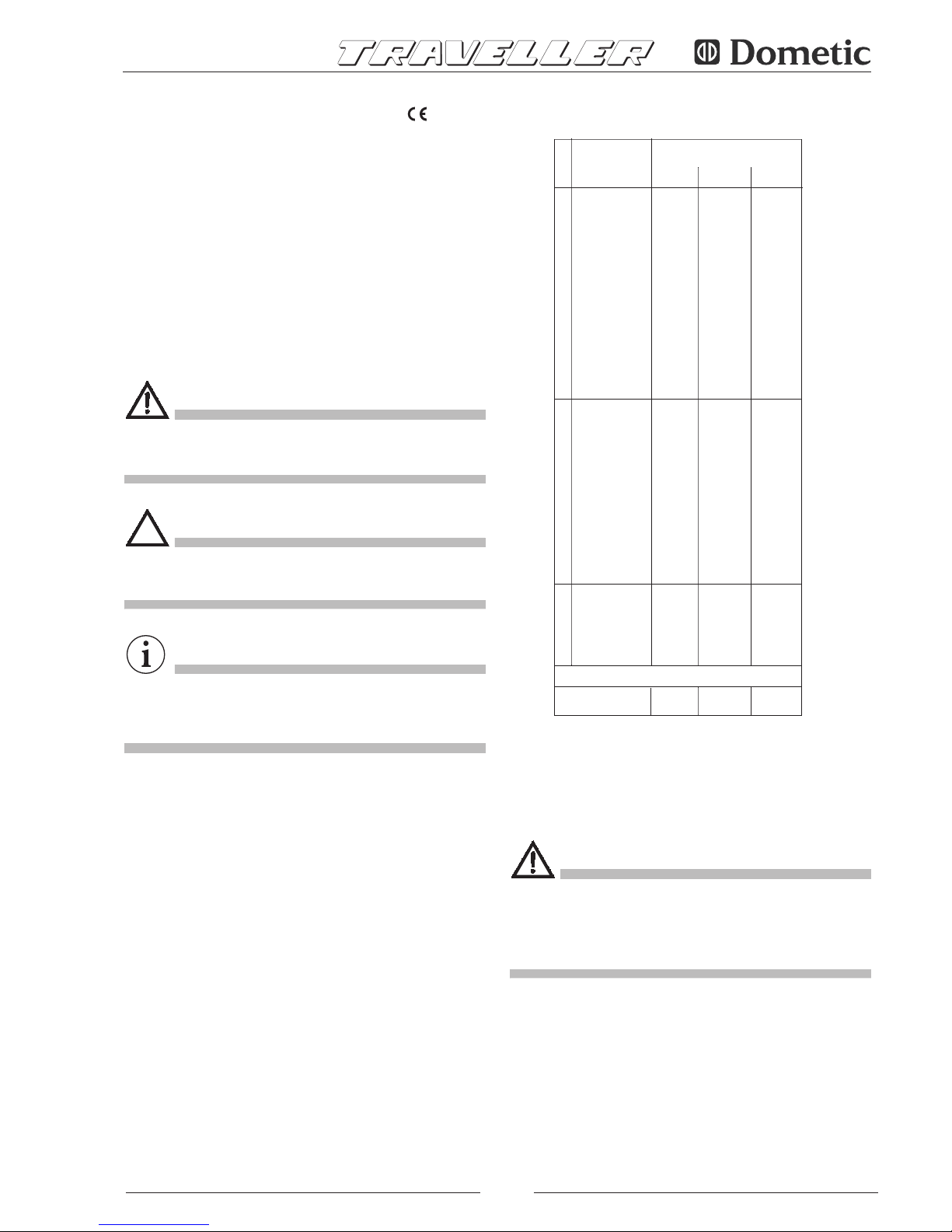
5.1 NATURE AND FREQUENCY OF CHECKS
5.2 MAINTENANCE OPERATIONS WHICH
DO NOT REQUIRE QUALIFIED
TECHNICIANS
To carry out these operations, the generator door first
needs to be opened. Therefore, the following measures
should be taken:
1) The generator must be stopped with all parts cold.
2) Let the unit cool.
3) Set the safety switch to the “0” position.
N.B.Remember to set it to the “I” position again after check!
OIL LEVEL CHECK
1) Remove the oil filling cap (pos. 9 fig. 8) and clean the
dipstick.
2) Reintroduce the dipstick by screwing it in fully.
3) Remove the dipstick and check that the oil level is
between min. and max. levels.
If not, top up with the recommended oil.
4) Refit the cap.
IMPORTANT
All checks should be carried out with the genset horizontal.
5.3 MAINTENANCE OPERATIONS WHICH
REQUIRE QUALIFIED TECHNICIANS
For some maintenance operations you need to slide the unit
out on its runners (pos. 28 fig. 7 and 15) after first loosening
the fixing screws.
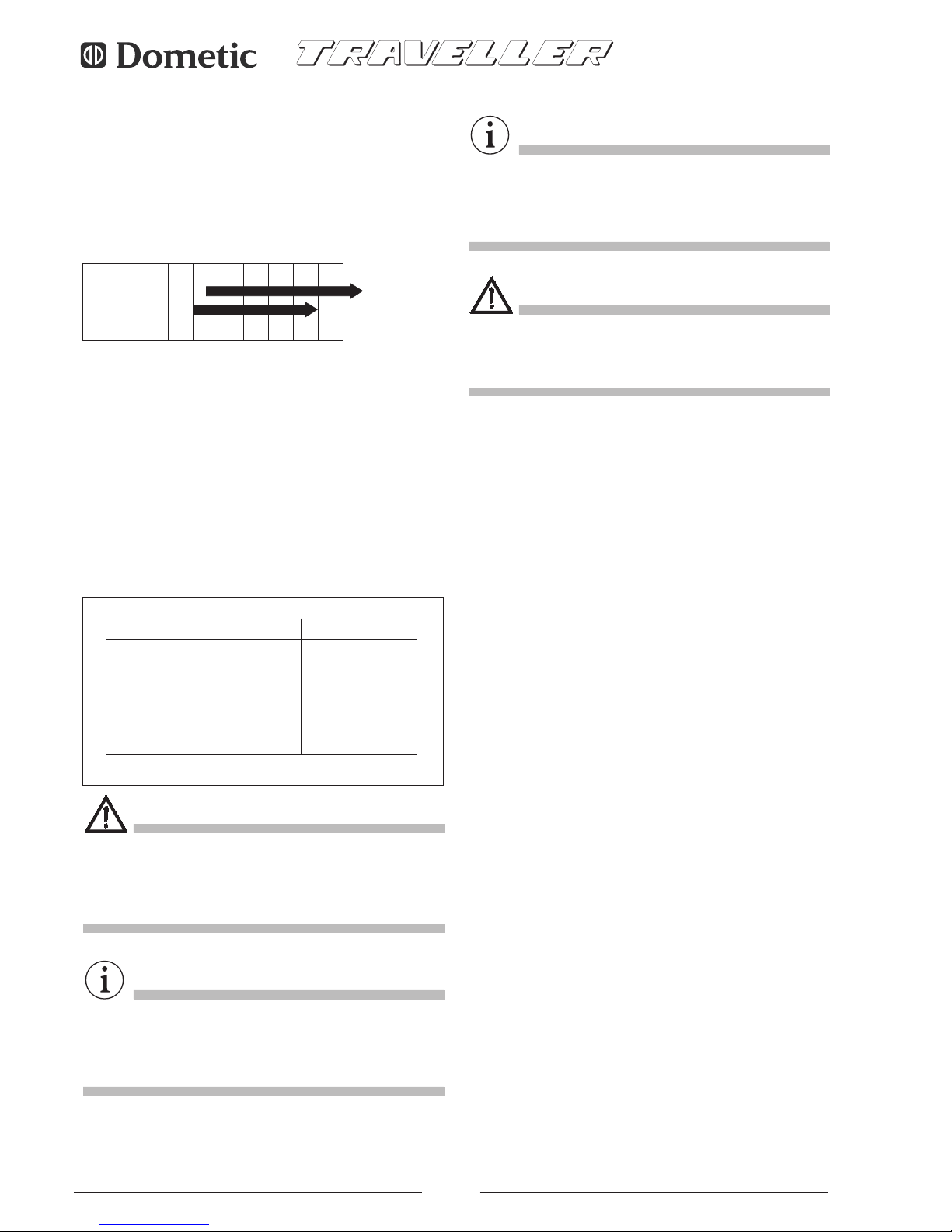
Inspection
▲
Change
▲
(2)
▲
(2)
Air filter Cleanin
g
(1) ▲(2)
Spark plug
Inspection-Cleaning
▲
(2)
Valve adjustment Check - adjust ▲
(2)
Fuel filter and tank
Cleaning ▲
(2)
R.p.m.
or frequency Adjust ▲
(2)
▲
(2)
Suspension points for
vibration dampers In
spection ▲
(2)
Fuel hoses Check (replace,
Every two years
(2)
if necessary)
REMARK (1):Clean more frequently when used in dusty areas
(2): Get this work done by a specialist only
ORDINARY MAINTENANCE INTERVAL
carry out at the intervals or after the running
hours given in the table, depending on which
occurs first.
Every
year
or
300 hours
Every
6 months
or
100 hours
First
month
or
20 hours
Every
3 months
or
50 hours
Every
use
Engine oil
Page 9
7
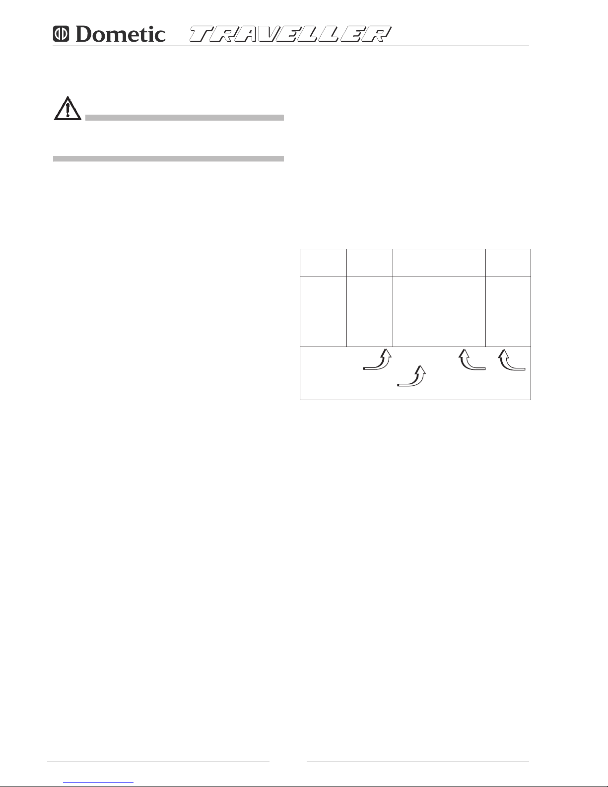
5.3.1 OIL CHANGE
Use detergent oil for fourstroke engines, class API SG or SF
(indicated on the oil can) with SAE viscosity suitable for the
climate (see table).
To allow the oil to drain out easier, run the engine for about
3÷5 minutes. Then discharge the oil when the engine is still
warm so that the emptying is quicker and more complete via
the drainage hose (pos. 2 fig. 8 and 15) by removing the
drain cap (pos. 8 fig. 8 and 15).
Top up with oil of the recommended type via the filling cap
(pos. 9 fig. 8).
Table 2 shows the amount of oil in the oil pan.
Mod. Liters
2500 0.6
4000 1.1
5500 1.1
TA
B. 2
DANGER
• Warm oil may burn you.
• Running the engine with a poor amount of oil can
seriously damage the engine itself.
• Check the oil level when engine is stopped.
IMPORTANT
Used oils must never be poured on the ground. They shall
be collected and consigned to qualified companies for the
disposal in accordance with any local regulations.
5.3.2 AIR FILTER MAINTENANCE
IMPORTANT
A dirty air filter reduces the air flow to the carburettor. To
keep the carburettor working properly, check it often. Check
more frequently if the engine is used in dusty areas.
DANGER
Never use diesel oil or solvents with a low evaporation point
for cleaning the air filter, since this may lead to danger of
flames or explosion.
Never let the engine run without the air filter. It would get
damaged in a short space of time.
1. Carefully check both cartridges. Replace them if there
are holes or tears
2. Sponge cartridge: wash it with a neutral detergent
so
lution and rinse carefully. Let the cartridge dry
completely, then soak it in clean engine oil and wring out
the excess.
3. Paper cartridge: smoothly beat it several times on a hard
surface to remove any dirt, or blow compressed air
through the filter from inside to out. Do not brush the dirt:
this operation would just push it into the fibres. If the
paper cartridge is too dirty, replace it.
5.3.3 SPARK PLUG MAINTENANCE
RECOMMENDED SPARK PLUG:
Mod. 2500/4000/5500
BP6ES, BPR6ES NGK
W20EPU, W20EPRU ND
Never use a spark plug with a different thermal degree.
1. Remove the spark plug nipple (pos. 1 fig. 8) and use a
suitable wrench to remove the spark plug.
2. Visually check the spark plug. If it is worn or if the
insulator is broken or chipped, replace it. Clean the
spark plug with an iron brush if it is to be used again.
3. Measure the electrode distance by means of a thickness
gauge.
The distance should be 0.70.8 mm.
Adjust, if necessary, by bending the side electrode.
4. Check that the spark plug washer is in good condition
and screw it manually to prevent it being set at an angle.
5. Once mounted, tighten the spark plug using a wrench
with the right driving torque.
-30° -20 ° -10 ° 0 10 ° 20° 30 ° 40°
Room Temperature
MULTIGRADE
SG / SF
Hot climates
Cold climates
10W 30
15W 50
Page 10
8
IMPORTANT
When mounting a new spark plug, tighten it a halfturn after
it has compressed the washer. When reusing the same
spark plug, tighten it 1/81/4 turn after the washer
compression.
CAUTION
The spark plug should be tightened carefully. A loose spark
plug can get very hot and damage the engine.
5.3.4 REGULATING THE VOLTAGE
This regulation should be carried out with the engine warm
and the generator running without a load.
Check the generator voltage using a tester or voltmeter
connected to the vehicle's 230V socket or to the terminals
(pos. 1718 fig. 6 and 14) of the generator terminal board.
The voltage should be between 230 and 240 Volts.
If these values are not obtained, adjust the current regulation
screw (pos. 32 fig. 10 and 15) until they are.
Rotate clockwise to increase the voltage.
Rotate anticlockwise to decrease both r.p.m. und voltage.
6.00 INACTIVITY AND DISMANTLING
6.01 DISMANTLING
If the unit must be dismantled, get the work done by
authorised workshops.
7.0 DEALING WITH FIRE HAZARDS
In case of fire, do not open the generator casing and use
typeapproved fireextinguishers.
Page 11
9
8.0 TECHNICAL DATA
8.1 TECHNICAL SPECIFICATIONS
ENGINE 2500H 4000H 5500H
Type
Si
nglecylinder, fourstroke,
overhead valves
Honda model GX
160 GX 270 GX 390
Displacement cm
3
163 270 389
Stroke x bore m
m 68x45 77x58 88x64
Consumption gk
W/h 230 230 235
Fuel Leadfree petrol
St
arter system Electronic
Sp
ark plug NGK NGK NGK
En
gineoil sump capacity litre 0.6 1.1 1.1
F
requency r eg o l a t or Automatic with centrifugal masses
T
ype
Pe
ak max. power W 2200 3800 5300
Fo
r continuous utilization W 2000 3500 4500
Vo
ltage/frequence 23
0V 50Hz
D.C. power 12V 10A 12V 10A 12V 10A
Ro
tor insulation class H H H H
S
tator insulation class F
F F F
Cooling Centrifugal fan
GENERATOR 2500H 4000H 5500H
Total weight Kg 50 102 132
Ov
erall dimensions
(LxWxH)
mm
530x385x290 660x475x355 700x520x510
Ignition Electric/man.
Fuel pump Vacuum
Re
mote control Se
parate control board with:
pushbutton starter
pu
shbutton choke
st
op switch
lo
w fuel LED
ru
nning LED
lo
w oil LED (automatic stop)
ho
ur meter
ALTERNATOR 2500H 4000H 5500H
Synchronous, singlephase, selfregulated,
selfenergized, twopole, brushless
Page 12
10
INDICE
Descrizione Pagina
1.0 Identificazione .................................................. 11
1.1 Costruttore ...................................................... 11
1.2 Definizioni ........................................................ 11
1.3 Trasporto Movimentazione
Immagazzinamento .......................................... 11
1.3.1 Condizioni di immagazzinamento ..................... 11
1.3.2 Peso ................................................................ 11
1.3.3 Dimensioni d'ingombro .................................... 11
1.3.4 Movimentazione ............................................... 11
2.0 Installazione .................................................
11
2.1 Personale autorizzato ....................................... 11
2.2 Istruzioni per il fissaggio del generatore ............ 12
2.3 Istruzioni per il collegamento elettrico ............... 12
2.3.1 Collegamento elettrico del carica batterie ......... 12
2.3.2 Collegamento batteria ...................................... 12
2.3.3 Collegamento cruscotto comando a distanza .. 12
2.4 Istruzioni per l'installazione serbatoio
carburante ....................................................... 13
3.0 Indicazioni e funzionamento .....................
13
3.1 Descrizione del generatore e funzionamento .... 13
3.2 Sicurezza delle macchine ................................. 13
3.3 Indicazione sul rumore ..................................... 13
4.0 Uso del generatore .....................................
14
4.1 Avviamento del generatore............................... 14
4.2 Arresto del generatore ..................................... 14
4.3 Informazione sui pericoli ineliminabili................. 14
4.4 Informazione sugli usi non consentiti ................ 14
4.5 Consigli utili ...................................................... 14
4.6 Indicazioni per l'individuazione dei guasti.......... 14
5.0 Indicazioni per la manutenzione ..............
15
5.1 Natura e frequenza delle verifiche ..................... 15
5.2 Interventi manutentivi che non richiedono
personale qualificato ........................................ 15
5.3 Interventi manutentivi che richiedono
personale qualificato ........................................ 16
5.3.1 Sostituzione olio ............................................... 16
5.3.2 Manutenzione filtro aria .................................... 16
5.3.3 Manutenzione candela ..................................... 16
5.3.4 Regolazione della tensione ............................... 17
6.0 Indicazioni per la messa fuori servizio ....
17
6.1 Smantellamento ............................................... 17
7.0 Mezzi antin
cendio da utilizzare ................ 17
8.0 Dati tecnici ................................................... 18
8.1 Caratteristiche tecniche.................................... 18
8.2 Schemi elettrici .......................................... 55÷69
© Dometic Italy
spa
Tutti i diritti riservati
Stampato in Italia
Realizzazione: VEGA Forlì
INDICE GENERALE
................................................ Pag. 1÷9
................................................ Pag. 10÷18
................................................ Pag. 19÷27
................................................ Pag. 28÷36
................................................ Pag. 37÷45
................................................ Pag. 46÷54
I
D
NL
F
SP
GB
Nessuna parte di questo manuale può essere riprodotta, copiata o divulgata con qualsiasi mezzo senza l’autorizzazione scritta della
Dometic Italy
spa.
Le figure, le descrizioni, i riferimenti ed i dati tecnici contenuti nel presente manuale sono indicativi e non impegnativi.
La Dometic Italy
spa si riserva il diritto di apportare in qualsiasi momento e senza preavviso tutte le modifiche che riterrà opportuno, nella
costante ricerca di migliorare la qualità e la sicurezza, senza impegnarsi ad aggiungere di volta in volta questo manuale.
Page 13
11
1.3.3 DIMENSIONI D'INGOMBRO
Vedere figg. 2, 3, 4 :
1.3.4 MOVIMENTAZIONE
Il generatore completo di imballo è movimentabile con i
comuni mezzi di sollevamento e trasporto.
Le casse sono dotate di distanziali per l’utilizzo di transpallet.
PERICOLO
Durante le fasi di sollevamento e trasporto rispettare le
norme antinfortunistiche e di sicurezza ed utilizzare
macchine con portata massima superiore al carico da
sollevare.
2.0 INSTALLAZIONE
2.1 PERSONALE AUTORIZZATO
Il generatore deve essere installato sul mezzo (camper,
motor home o veicoli speciali) solo ed esclusivamente da
ditte o personale qualificato ed autorizzato dalla W.T.A.
Qualora l’installazione sia effettuata da personale o da ditte
1.0 IDENTIFICAZIONE
La targhetta di identificazione della macchina è fissata
all'esterno della cassa in lamiera (vedi fig. 1).
1.1 COSTRUTTORE
Dometic Italy spa
Via Virgilio, 3
47122 FORLI' ITALY
P. IVA 00718330400
1.2 DEFINIZIONI
In questo libretto sono utilizzati tre "simboli grafici di sicurez
za", che hanno lo scopo di evidenziare altrettanti livelli di
pericolo o importanti informazioni:
PERICOLO
Richiamo che indica una situazione potenzialmente perico
losa che, potrebbe provocare infortuni gravi.
ATTENZIONE
Richiamo che indica una situazione potenzialmente perico
losa che potrebbe provocare infortuni o danni a cose.
IMPORTANTE
Richiamo che indica una situazione potenzialmente perico
losa che potrebbe provocare mal funzionamenti o danni alla
macchina.
1.3 TRASPORTO - MOVIMENTAZIONE IMMAGAZZINAMENTO
1.3.1 CONDIZIONI DI IMMAGAZZINAMENTO
Il generatore viene protetto contro gli urti da un opportuno
imballaggio di cartone, polistirolo e base di appoggio in
legno.
Il generatore deve essere immagazzinato in posizione nor
male in ambiente coperto, asciutto e ventilato.
1.3.2 PESO
Peso lordo completo di imballaggio:
Mod. 2500 .......................................... Kg 62
Mod. 4000 .......................................... Kg 114
Mod. 5500 .......................................... Kg 140
Modello
2500 4000 5500
A
mm 470 660 700
B
mm 535 740
C
mm 565 770
D
mm 320 475 515
E
mm 315 355 510
F
mm 260 310
G
mm 27 62
H
mm
I
mm 65 78
L mm 65 265
M mm 225 130
N
mm 36 17
O mm 535 740 735
P
mm 27 62 55
Q mm 260 310 370
X
mm 590 780 770
Y
mm 385 540 505
Z
mm 335 380 550
Area feritoie sportello
c
m
2
220 260
INSTALLAZIONE TIPO “B” INSTALLAZIONE TIPO “A”
DIM. VANO
Page 14
12
del generatore. Per evitare il riciclo dei gas di scarico dentro
il vano è necessario inserire una guarnizione di tenuta
ignifuga, attorno al raccordo di scarico.
2.3 ISTRUZIONI PER IL COLLEGAMENTO
ELETTRICO
Usare per la 230V un cavo a norme la cui sezione è da
rilevare in tab. 1; inserirlo nella cassa tramite il passacavo
(pos. 30 fig.7 e 9 ) e collegarlo ai morsetti (pos.17/18 fig.6
e 14). In pos.15 fissare il cavo di terra.
Occorre installare sull’impianto elettrico del mezzo un relè o
commutatore (es. l'accessorio AG102/AG113) per non
danneggiare il generatore quando è allacciato alla rete
d'alimentazione esterna: bisogna dare la precedenza alla
rete esterna.
2.3.1 COLLEGAMENTO ELETTRICO DEL CARICA BATTERIE
Usare un cavo la cui sezione è da rilevare in tab. 1,
collegandolo al morsetto (pos.16 fig.6 e 14) e al polo
positivo della batteria che si vuole caricare.
E' consigliabile inserire il regolatore di tensione AG 111 o un
interruttore per interrompere la carica sulla batteria.
(Vedere schemi elettrici a pag. 55 ÷ 71)
2.3.2 COLLEGAMENTO BATTERIA
Per l’avviamento del generatore collegarsi al polo positivo
della batteria di avviamento del mezzo con un cavo a norme
inguainato la cui sezione è da rilevare in tab. 1 e collegarlo
in pos.12 fig.6 e 14.
Il cavo di massa deve avere la stessa sezione e va collegato
in pos.13 e al telaio del mezzo. Occorre assicurarsi che il
contatto sia buono, asportando se necessario la vernice o
la ruggine dalla superficie, proteggendo il collegamento con
grasso.
2.3.3 COLLEGAMENTO CRUSCOTTO COMANDO A DISTANZA
Scegliere la posizione desiderata all'interno del mezzo e
usufruire della prolunga AG 103 per il collegamento del
cruscotto al generatore tramite il connettore pos. 14 fig. 6
e 14.
non autorizzate, la W.T.A. declina ogni responsabilità sul
buon funzionamento e sulla sicurezza in base alla D.M. 89/
392/CEE.
PERICOLO
Le indicazioni riportate ai punti 2.2 2.3 2.4 sono ad uso
esclusivo degli installatori specializzati.
2.2 ISTRUZIONI PER IL FISSAGGIO DEL GENERATORE
I generatori mod. 2500 4000 sono forniti con
la dotazione di staffe per l'ancoraggio del gruppo con
antivibranti supplementari e filtro benzina da interporre
lungo il tubo di aduzione carburante al generatore. Le staffe
permettono il montaggio sia in sospensione: montaggio di
“TIPO A” (vedi fig. 3), sia in modo tradizionale: montaggio di
“TIPO B” (vedi fig. 4).
Ciò è possibile grazie alla struttura portante dell’involucro
esterno.
Il generatore mod. 5500 è fornito di serie con la dotazione
di staffe per il fissaggio della guarnizione di finitura, staffe per
l'ancoraggio del gruppo con antivibranti supplementari,
silenziatore (pos. 29 fig. 16) da montare in linea al tubo di
scarico fornito come accessorio AG 125 (pos. 34 fig. 16) e
filtro benzina montato di serie all'interno della cassa (pos. 33
fig. 15). Le staffe (pos. 31 fig. 16) per il fissaggio della
guarnizione (pos. 35 fig. 16) permettono di montare il
generatore completo di guarnizione nel vano predisposto,
sigillando perfettamente sul fianco del mezzo. Il tubo di
scarico può essere indirizzato a scelta come indicato in fig.
16, ruotando la curva all'interno della macchina in posizione
superiore, inferiore oppure, togliendola, è possibile entrare
direttamente con il tubo di scarico attraversando la cassa
sul fianco sinistro. Il piano d'appoggio predisposto dovrà
sopportare, oltre al peso del generatore, anche le sollecita
zioni del mezzo in movimento (montaggio di “TIPO B”).
Il montaggio di “TIPO A” (installazione esterna) offre i se
guenti vantaggi: minor spazio di ingombro, rapida installa
zione, facile accesso per le operazioni di normale e straor
dinaria manutenzione.
Occorre assicurarsi che attorno al cofano del generatore vi
sia spazio sufficiente per il passaggio d’aria di raffredda
mento; inoltre lasciare almeno 20 mm di spazio libero fra il
cofano e le parti circostanti.
Nel caso in cui la presa d’aria di aspirazione del generatore
resti dietro a una ruota del mezzo, occorre impedire che, in
caso di pioggia, la ruota del mezzo butti acqua dentro al
generatore.
Per il montaggio di “TIPO A” è necessario usufruire dei due
supporti di lamiera in dotazione per garantire un solido
fissaggio del gruppo.
Se si decide di adottare il montaggio di “TIPO B” (installazio
ne interna) , occorre predisporre un vano a tenuta stagna
(fig. 2) verso l’interno del mezzo con dimensioni minime
indicate al punto 1.3.3, con i fori di scarico e prese d’aria
praticate sul pianale e sullo sportello. Occorre inoltre utiliz
zare il raccordo di scarico (fig. 4), fornito come accessorio,
che sarà fissato, tramite viti o rivetti, direttamente sul cofano
Mod. Sez.
mm2Sez.
mm
2
6 m > 6 m
230 V 12 V
2500 2,5 2,5 10 16
4000 4 2,5 10 16
5500 4 2,5 16 25
TA B. 1
Cavi di potenza
Collegamento batteria
Carica batteria
Page 15
13
2.4 ISTRUZIONI PER L’INSTALLAZIONE DEL
SERBATOIO
L’ubicazione del serbatoio deve essere scelta in modo da
ridurre al minimo la lunghezza del tubo carburante. Evitare
inoltre che la sezione del tubo possa essere ridotta per
strozzature, curvature o schiacciamenti. Si consiglia inoltre
di installare il serbatoio allo stesso livello del generatore o al
massimo 30 cm sotto. Non posizionare il serbatoio nelle
vicinanze di fonti di calore e al riparo da infiltrazioni esterne
di acqua.
Montare i raccordi con LOCTITE 577 per evitare il pericolo
di perdite di carburante.
Usare per il collegamento serbatoiogeneratore un tubo di
gomma rivestito adatto a benzina verde delle dimensioni 6
x13 dello stesso tipo usato nel gruppo. Per la prolunga è
indispensabile usufruire delle fascette e del filtro in dotazio
ne. Si consiglia di usare il tubo AG 118 (accessorio) per il
collegamento dal serbatoio al bocchettone.
IMPORTANTE
Il modello 5500 non necessita di serbatoio poichè è instal
lato di serie all'interno della cassa.
COLLEGAMENTO DELLA BOMBOLA GAS GPL
ATTENZIONE
Il gruppo ad alimentazione GPL deve prelevare il gas della
bombola in posizione verticale e dalla parte superiore, dopo
il rubinetto e DOPO il regolatore della bombola, perchè
l'alimentazione avvenga allo stato gassoso e in bassa pres
sione.
(Pressione minima consigliata: 0.30 mbar)
3.0 INDICAZIONI E FUNZIONAMENTO
IMPORTANTE
La ditta non risponde dei danni dovuti al mancato funziona
mento del generatore.
3.1 DESCRIZIONE DEL GENERATORE E
FUNZIONAMENTO
Il generatore di corrente è costituito da un motore
endotermico a benzina collegato ad un alternatore che
produce corrente elettrica alternata e continua.
Il gruppo è montato all’interno di un cofano in lamiera
d’acciaio stampato isolato ed insonorizzato con speciali
materiali fonoassorbenti.
L’alimentazione del carburante al motore endotermico av
viene tramite una pompa montata di serie sul generatore.
3.2 SICUREZZA DELLE MACCHINE
Il gruppo è alloggiato nel cofano perfettamente chiuso
pertanto non esiste il rischio di contatto con parti mobili, con
temperature elevate, o con conduttori sottotensione.
Lo sportello è dotato inoltre di apertura con serratura a
chiave che non deve essere lasciata alla portata dei bambini
o di persone inesperte.
PERICOLO
• Il gruppo deve essere utilizzato solo ed esclusivamente
a sportello chiuso.
• Allontanare le sostanze infiammabili dal generatore quali
ad esempio: benzina, vernici, solventi, ecc.
• Assicurarsi che le parti calde del gruppo non siano in
contatto con materiali facilmente infiammabili.
• Non fare il pieno di benzina con il motore in moto se il
serbatoio è posto nelle vicinanze del generatore.
• Non toccare il generatore o i collegamenti con le mani
bagnate.
• Non sostituire i fusibili o termici con altri di amperaggio
maggiore.
• Eventuali controlli di parti elettriche vanno eseguiti a
motore spento, e solo da personale autorizzato.
Il generatore è realizzato secondo le norme di sicurezza
indicate nella dichiarazione di conformità.
3.3 INDICAZIONE SUL RUMORE
Il generatore è stato sottoposto ad esame di emissione
acustica presso il laboratorio qualificato ISTEDIL che ha
provveduto ad eseguire le prove rilasciando certificato CEE.
N° I225/92 con i seguenti risultati:
Misurazioni DIRETTIVA CEE 84/536
LIVELLO DI POTENZA ACUSTICA:
Mod. 2500 .......................................... LwA 85
Mod. 4000 .......................................... LwA 87
Mod. 5500 .......................................... LwA 87
Page 16
14
4.0 USO DEL GENERATORE
4.1 AVVIAMENTO DEL GENERATORE
L’avviamento del gruppo avviene normalmente tramite
batteria a 12 volt in dotazione al veicolo.
Prima di procedere all’avviamento del motore posizionare
l’interruttore rosso (pos. 27 fig. 5) in posizione "I".
Per l’avviamento a motore freddo premere e mantenere
premuto il pulsante verde d'avviamento (pos. 25 fig. 5)
insieme al pulsante bianco "aria" (pos. 26 fig. 5) per un
tempo
non superiore ai 5 secondi.
ATTENZIONE
Non insistere mai più di 5 tentativi consecutivi vi è il rischio
di danneggiare il motorino di avviamento.
Per l’avviamento a motore caldo o d’estate, quando la
temperatura ambiente è molto elevata premere solo il
pulsante verde “avviamento” (pos. 25 fig. 5).
In caso di emergenza si può avviare il gruppo manualmente
utilizzando l'impugnatura di avviamento (pos. 4 fig. 8 e 15);
se il motore è freddo bisogna agire anche sull'asta di
comando dell'elettromagnete (pos. 36 fig. 8 e 15) fino a
portare la leva dell'aria in posizione chiusa.
Il corretto funzionamento è evidenziato dalla spia verde
(pos. 23 fig. 5).
4.2 ARRESTO DEL GENERATORE
Premere in posizione "0" l’interruttore rosso “STOP” (pos.
27 fig. 5). In alternativa, solo per i modd. 2500 40005500
usare l'interuttore di sicurezza (pos. 7 fig. 6 e 14).
4.3 INFORMAZIONE SUI PERICOLI INELIMINABILI
PERICOLO
Il generatore è dotato di motore a scoppio, quindi il carbu
rante utilizzato è altamente infiammabile.
Sotto al cofano vengono convogliati i gas di scarico che,
inevitabilmente, hanno temperature piuttosto elevate anche
se miscelati all’aria di raffreddamento.
Non toccare le zone del cofano vicine allo scarico e non
inserire le mani od oggetti vari nel cofano
4.4 INFORMAZIONE SUGLI USI NON CONSENTITI
PERICOLO
Il generatore deve essere installato solo ed esclusivamente
da personale qualificato ed autorizzato secondo le indica
zioni fornite dal costruttore.
Il generatore deve essere impiegato ed utilizzato solo ed
esclusivamente per la produzione di corrente elettrica su
mezzi mobili dotati di impianto elettrico realizzato secondo
le normative ed in base alla potenza erogata dal generatore.
4.5 CONSIGLI UTILI
Per utilizzare al meglio il gruppo elettrogeno è bene tenere
presente che anche sovraccarichi di piccola entità, se
prolungati, provocano il disarmo dei termici di protezione
pos. 10 e 11 di fig. 6 e 14.
Nel periodo di rodaggio è importante non sottoporre il
motore nuovo ad un carico superiore al 70% del carico
nominale almeno per le prime 50 ore di funzionamento.
4.6 INDICAZIONE PER L'INDIVIDUAZIONE
DEI GUASTI
Vi elenchiamo gli inconvenienti che possono eventualmente
presentarsi; con relativa causa e possibili rimedi.
Per i guasti non previsti rivolgersi ad un centro assistenza
autorizzato o specializzato.
1 Premendo il pulsante verde “AVVIAMENTO”
(pos. 25 fig. 5) sul cruscotto non si riscontra
alcun funzionamento.
Cause e Rimedi:
1.1 Verificare che l’interruttore rosso (pos. 27 fig. 5) sia in
posizione "I".
1.2 Cavi elettrici interrotti.
(Fare controllare da personale qualificato).
1.3 Motorino di avviamento non alimentato.
(Fare controllare da personale qualificato).
1.4 Cavo di massa del generatore interrotto.
(Fare controllare da personale qualificato).
2 Il motorino di avviamento gira ma il generatore
non parte.
Cause e Rimedi:
2.1 Mancanza di carburante: controllare.
2.2 Mancanza olio nel motore.
Controllare se durante l’avviamento la spia rossa sul
cruscotto (pos. 6 fig. 5) lampeggia.
Verificarne il livello e ripristinarlo (vedi indicazioni per
la manutenzione).
2.3 Interruttore di sicurezza (pos. 7 fig. 6 e 14) in posizio
ne "0".
Verificare e portare in posizione "I".
2.4 Controllare che il cappuccio della candela motore sia
inserito correttamente.
2.5 Non arriva corrente alla candela.
Page 17
15
(Fare controllare da personale qualificato).
2.6 Non arriva benzina al carburatore.
(Fare controllare da personale qualificato).
3 Il generatore tende a spegnersi.
Cause e Rimedi:
3.1 Sta per finire il carburante nel serbatoio: fare riforni
mento.
3.2 Livello olio insufficiente.
Controllare e ripristinare il livello.
(Vedi indicazioni per la manutenzione).
3.3 Filtro aria sporco.
(Fare controllare da personale qualificato).
4 Il generatore non eroga tensione.
Cause e Rimedi:
4.1 Protezione termica disinserita.
Reinserirla premendo gli interruttori (pos.10 fig. 6 e
14)
per tensione alternata 230 V; (pos.11 fig. 6 e 14)
per tensione continua 12 V.
4.2 Condensatore (pos. 19 fig. 8) danneggiato.
(Fare controllare da personale qualificato).
4.3 Ponte diodi (pos. 21 fig. 8) danneggiato.
In questo caso non funziona solo la tensione conti
nua 12 V ed è segnalato dal non funzionamento del
LED verde sul cruscotto.
(Fare controllare da personale qualificato).
4.4 Diodi rotore danneggiati.
(Fare controllare da personale qualificato).
4.5 Numero di giri troppo bassi.
(Fare controllare da personale qualificato).
5 La tensione prodotta senza carico inserito oscil
la.
Cause
e Rimedi:
5.1 Troppo olio nel motore: controllare.
5.2 Carburazione difettosa.
Fare pulire il carburatore da personale qualificato.
5.0 INDICAZIONI PER LA MANUTENZIONE
IMPORTANTE
Usare solo ricambi originali. L'uso di parti di ricambio non di
equivalente qualità possono danneggiare il generatore.
Il controllo periodico e le regolazioni sono essenziali affinché
l'alto livello di prestazioni venga mantenuto. La manutenzio
ne regolare assicura inoltre lunga vita al generatore.
PERICOLO
Prima di eseguire qualsiasi controllo o intervento di manu
tenzione sul generatore, ruotare l'interruttore di sicurezza
(pos. 7 fig. 6 e 14) in posizione "0" al fine di evitare partenze
accidentali del gruppo.
5.1 NATURA E FREQUENZA DELLE
VERIFICHE
5.2 INTERVENTI MANUTENTIVI CHE NON
RI
CHIEDONO PERSONALE QUALIFICA-
T
O
Per eseguire questi controlli occorre aprire lo sportello del
generatore pertanto occorre adottare le seguenti precau
zioni:
1) Il generatore non deve essere in funzione e tutte le parti
devono essere fredde.
2) Lasciare raffreddare.
3) Girare l’interruttore di sicurezza in posizione "0".
N.B. Ricordarsi di rimetterlo in posizione "I" terminato i
controlli.
CONTROLLO LIVELLO OLIO
1) Sfilare il tappo di rifornimento olio (pos. 9 fig. 8) e pulire
l’asta.
2) Reinserirla fino in fondo.
3) Sfilare l’asta e controllare che il livello dell’olio sia com
preso fra le due tacche (min.max.).
In caso contrario ripristinare il livello con olio raccoman
dato.
4) Reinserire il tappo.
IMPORTANTE
Eseguire tutte le operazioni di controllo con il generatore in
piano.
Ispezione ▲
Cambio ▲
(2)
▲
(2)
Filtro aria Pulizia (1) ▲(2)
Candela Ispezione -
Pulizia ▲
(2)
Registrazione valvole Controllare - regolare ▲
(2)
Serbatoio e filtro carburante
Pulizia ▲
(2)
Numero di giri
o frequenza Regolar
e ▲
(2)
▲
(2)
Punti di sospensione
antivibranti Cont
rollare ▲
(2)
Tubazioni carburante Controllare (e sostituire
Ogni due anni
(2)
se necessario)
NOTA (1): Pulire più frequentemente se usato in aree polverose
(2): Questi interventi devono essere eseguiti solo da personale specializzato
INTERVALLO DI ASSISTENZA PERIODICA
da eseguire agli intervalli o al numero di ore di
funzionamento indicate, a seconda di quale
caso si verif
ica prima.
Ogni
anno
o
300 ore
Ogni
6 mesi
o
100
ore
Primo
mese
o
20 ore
O
gni
3 mesi
o
50
ore
Ogni
uso
Olio motore
Page 18
16
5.3 INTERVENTI MANUTENTIVI CHE RICHIEDONO PERSONALE QUALIFICATO
Per alcune operazioni di manutenzione è prevista la possi
bilità di sfilare il gruppo, questa operazione è possibile
tramite la slitta (pos. 28 fig. 7 e 15) dopo aver allentato le viti
di bloccaggio.
5.3.1 SOSTITUZIONE OLIO
Usare olio detergente per motori a 4 tempi di categorie API
SG o SF (tale indicazione è riportata sul contenitore dell’olio)
con viscosità SAE appropriata al clima di esercizio (vedi
tabella).
Per rendere più agevole l'operazione di estrazione dell'olio
è preferibile far scaldare la macchina per circa 3÷5 minuti,
in tal modo l'olio sarà più fluido e lo svuotamento più rapido
e completo tramite il tubo di scarico (pos. 2 fig. 8 e 15) dopo
aver tolto il tappo di scarico (pos. 8 fig. 8 e 15).
Ripristinare il livello con l'olio del tipo raccomandato tramite
il tappo pos.9 fig. 8.
La quantità di olio contenuta nel carter è indicata in tab. 2.
Mod. Quantità litri
2500 0,6
4000 1,1
5500 1,1
TA
B. 2
PERICOLO
• L'olio caldo può provocare ustioni.
• Facendo girare il motore con livello di olio insufficiente
lo si può danneggiare gravemente.
• Controllare il livello dell'olio a motore spento.
IMPORTANTE
Gli oli esausti non devono essere dispersi nell'ambiente, ma
affidati a Ditte specializzate allo smaltimento e/o riciclaggio
attenendosi alle leggi vigenti nel paese dove si compiono tali
operazioni.
5.3.2 MANUTENZIONE FILTRO ARIA
IMPORTANTE
Il filtro aria sporco (pos. 3 fig. 8,11 e 15) riduce il flusso di
aria al carburatore. Per prevenire mal funzionamenti al
carburatore, controllare regolarmente. Controllare più fre
quentemente se il motore viene usato in zone polverose.
PERICOLO
Non usare gasolio o solventi a basso punto di evaporazione
per la pulizia dell’elemento del filtro aria. Potrebbero svilup
parsi fiamme o esplosioni.
Non fare mai funzionare il motore senza il filtro dell’aria. Il
motore si usurerebbe in breve tempo.
1 Controllare attentamente entrambi gli elementi da even
tuali fori o strappi e sostituirli se danneggiati
2 Elemento in spugna: lavare l’elemento in una soluzione
contenente detergente neutro, risciacquare accurata
mente. Lasciare asciugare completamente l’elemento
ed immergerlo in olio motore pulito quindi strizzare
l’eccesso di olio.
3 Elemento in carta: battere dolcemente alcune volte
l’elemento su una superficie dura per rimuovere l’ecces
so di sporcizia, o soffiare con aria compressa il filtro
dall’interno verso l’esterno. Non spazzolare mai la spor
cizia; la spazzolatura spingerebbe la sporcizia ad entrare
nelle fibre. Sostituire l’elemento in carta se eccessiva
mente sporco.
5.3.3 MANUTENZIONE CANDELA
CANDELA RACCOMANDATA:
Mod. 2500/4000/5500
BP6
ES, BPR6ES NGK
W20EP-U, W20EPR-
U ND
Non usare mai una candela con grado termico diverso.
1. Rimuovere il cappuccio della candela
(pos. 1 fig. 8) e
usare la chiave per rimuovere la candela.
2
Controllare visivamente la candela. Sostituire se vi è una
apparente usura o se l’isolatore è rotto o scheggiato.
Pulire la candela con una spazzola in setole d'acciaio se
può essere riutilizzata.
3 Misurare la distanza degli elettrodi con uno spessimetro.
La distanza deve essere di 0,70,8 mm.
Correggere se necessario piegando l’elettrodo laterale.
4 Controllare che la rondella della candela sia in buone
condizioni ed avvitare manualmente per evitare di inse
rirla storta.
5 Dopo che la candela è montata, serrare con la chiave alla
giusta coppia.
10W 30
-30° -20 ° -10 ° 0 10 ° 20 ° 30 ° 40°
Temperatura ambiente
MULTIGRADO
SG / SF
Per climi caldi
Per climi freddi
15W 50
Page 19
17
IMPORTANTE
Quando si monta una candela nuova, serrare di 1/2 giro
dopo che la candela ha compresso la rondella. Se si sta
riutilizzando una candela, serrarla di 1/8 1/4 di giro dopo
che la stessa ha compresso la rondella.
ATTENZIONE
La candela deve essere accuratamente serrata. Una can
dela non serrata può diventare molto calda e causare danni
al motore.
5.3.4 REGOLAZIONE DELLA TENSIONE
La regolazione deve essere eseguita a motore caldo senza
nessun carico inserito e col generatore in funzione.
Controllare la tensione del generatore con un “tester” o un
voltometro tramite una presa a 230 V di servizio del mezzo
o ai terminali della morsettiera sul generatore (pos.17 18 fig.
6 e 14).
La tensione deve essere compresa fra i 230 e i 240 Volt
senza nessuna utenza inserita.
Se non si riscontrano tali valori occorre ripristinarli agendo
sulla vite di regolazione dell’acceleratore (pos. 32 fig. 10 e
15).
Girando la vite in senso orario si aumentano i giri e quindi la
tensione.
Girando la vite in senso antiorario per diminuire giri e
tensione.
6.00 INDICAZIONI PER LA MESSA FUORI
SERVIZIO E LO SMANTELLAMENTO
6.01 SMANTELLAMENTO
Nel caso in cui si debba procedere allo smantellamento del
gruppo, rivolgersi a officine specializzate.
7.0 MEZZI ANTINCENDIO DA UTILIZZARE
In caso di incendio non aprire assolutamente il cofano del
generatore ed usare estintori di tipo omologato.
Page 20
18
8.0 DATI TECNICI
8.1 CARATTERISTICHE TECNICHE
MOTORE 2500H 4000H 5500H
Tipo
Singlecylinder, fourstroke,
overhead valves
Modello Honda GX 160 GX 270 GX 390
Cilindrata cm
3
163 270 389
Alesaggio x Corsa mm 68x45 77x58 88
x64
Consumo gkW/h 230 23
0 235
Alimentazione Benzina verde
Sistema di accensione Elettronica
Candela NGK NGK NGK
Ca
pacità coppa olio motore litri 0.6 1.1 1.1
Regolatore di giri Automatic with centrifugal masses
T
ipo
P
otenza max istantanea W 2200 3800 5300
Pe
r uso continuo W 2000 3500 4500
Te
nsione/frequenza 230V 50Hz
Po
tenza corrente continua 12V 10A 12V 10A 12V 10A
Cl
asse isolamento rotore H H H H
Classe isolamento statore F F F F
Ra
ffreddamento Ventola centrifuga
GENERATORE 2500H 4000H 5500H
Peso complessivo Kg 50 102 132
Di
mensioni di ingombro
(Lungh.x Largh.x alt)
mm
5 3 0 x3 8 5 x2 9 0 6 6 0 x4 7 5 x 3 5 5 7 0 0 x5 2 0 x5 10
Avviamento Electric/man.
Pompa alimentazione Vacuum
Co
mando a distanza Cruscotto separato composto da:
pulsante avviamento
pulsante starter
interruttore stop
spia mancanza carburante
spia funzionamento
spia arresto per mancanza olio
contatore
ALTERNATORE 2500H 4000H 5500H
Sincronono, monofase, autoregolato,
autoeccitato, due poli senza spazzole
Page 21
19
INHALTSVERZEICHNIS
Beschreibung Seite
1.0 Identifikation .......................................
20
1.1 Hersteller ................................................ 20
1.2 Erläuterungen ......................................... 20
1.3 TransportBewegungLagerung .............. 20
1.3.1 Lagerbedingungen .................................. 20
1.3.2 Gewicht .................................................. 20
1.3.3 Abmessungen......................................... 20
1.3.4 Bewegung .............................................. 20
2.0 Installation ...........................................
20
2.1 Geschultes Fachpersonal ........................ 20
2.2 Montage des Generators ........................ 21
2.3 Elektranschluß ........................................ 21
2.3.1 Anschluß des Batterieladers .................... 21
2.3.2 Anschluß der Starterbatterie.................... 21
2.3.3 Anschluß des Bedienpaneels .................. 21
2.4 Installation des Benzintanks .................... 21
3.0 Funktionshinweise .............................
22
3.1 Beschreibung des Generators und
Funktionsweise ....................................... 22
3.2 Sicherheitshinweise ................................. 22
3.3 Lärmentwicklung ..................................... 22
4.0 Gebrauch des Generators ................ 23
4.1 Starten des Generators ........................... 23
4.2 Stoppen des Generators ......................... 23
4.3 Hinweise über unvermeidliche Gefahren.. 23
4.4 Hinweise über unsachgemäßen Gebrauch 23
4.5 Nützliche Hinweise .................................. 23
4.6 Hinweise für die Fehlersuche ................... 23
5.0 Wartung ................................................
24
5.1 Kontrollarten und zeitliche Abstände ....... 24
5.2 Wartungsarbeiten ohne Fachpersonal ..... 24
5.3 Wartungsarbeiten durch Fachpersonal .... 24
5.3.1 Ölwechsel ............................................... 25
5.3.2 Luftfilterreinigung..................................... 25
5.3.3 Zündkerzenwartung ................................ 25
5.3.4 Spannungsregulierung ............................ 26
6.0 Stillegung und Abrüstun
g ................. 26
6.1 Abrüstung ............................................... 26
7.0 Mittel zur Feuerbekämpfun
g ............ 26
8.0 Technische Einzelheiten ...................
27
8.1 Technische Daten ................................... 27
8.2 Elektropläne ............................................ 55÷69
© Dometic Italy spa
Alle Rechte vorbehalten
Gedruckt in Italien
Realisierung: VEGA Forlì
Kein Teil dieses Handbuchs darf ohne schriftliche Genehmigung der Fa. Dometic Italy
spa reproduziert, kopiert, oder auf sonstige Weise ver
breitet werden.
Die Abbildungen, Beschreibungen, Hinweise und technischen Daten in dem vorliegenden Handbuch sind unverbindlich und ohne Gewähr
Die Fa. Dometic Italy
spa behält sich das Recht vor, jederzeit und ohne vorherige Ankündigung alle Änderungen vorzunehmen, die sie im
Interesse der Verbesserung des Produkts und seiner Sicherheit für angebracht hält, ohne sich zur jedesmaligen Anpassung dieses Handbuchs
zu verpflichten.
ALLGEMEINES INHALTSVERZEICHNIS
............................................. Seiten 1÷9
............................................. Seiten 10÷18
............................................. Seiten 19÷27
............................................. Seiten 28÷36
............................................. Seiten 37÷45
............................................. Seiten 46÷54
I
D
NL
F
SP
GB
Page 22
20
1.3.3 ABMESSUNGEN
1.3.4 BEWEGUNG
Der verpackte Generator kann mit den handelsüblichen
Hebe und Beförderungsmitteln bewegt werden. Die Kisten
verfügen über Distanzstücke zum Einsatz eines manuellen
Gabelstaplers.
GEFAHR
Während der Hebe und Transportgänge sind die
Si cherheitsvorschri ften zur Unfallverhütung zu
berücksichtigen und die Tragfähigkeit der Maschinen muß
über der zu hebenden Last liegen.
2.0 INSTALLATION
2.1 GESCHULTES FACHPERSONAL
Der Generator darf auf Caravans, Wohnmobile oder
Spezialfahrzeuge nur von Fachpersonal mit der
Genehmigung der Firma Dometic Italyspa installiert werden.
Bei einer nicht fachgerechten Montage, Installation und
Anschluß kann es zu Fehlfunktionen und zu Gefährdungen
1.0 IDENTIFIKATION
Das Typenschild der Maschine ist auf dem Gehäuse
angebracht (siehe Abb. 1).
1.1 HERSTELLER
Dometic Italy spa
Via Virgilio, 3
47122 FORLI' ITALY
P. IVA 00718330400
1.2 ERLÄUTERUNGEN
In diesem Handbuch treten drei Arten von “grafischen
Sicherheitskennzeichen” zur Hervorhebung der jeweiligen
Gefahrenmomente oder Informationsarten auf:
GEFAHR
Die Aufmerksamkeit wird auf potentiell gefährliche Situationen
gelenkt, die die Sicherheit der Personen bedrohen und zu
Verletzungen führen können.
ACHTUNG
Die Aufmerksamkeit wird auf potentiell gefährliche Situationen
gelenkt, die die Sicherheit der Personen bedrohen und zu
leichten Verletzungen oder Schäden an der Maschine führen
können.
VERMERK
Die Aufmerksamkeit wird auf potentiell gefährliche Situationen
gelenkt, die die Leistungsfähigkeit und Betriebssicherheit
des Geräts beeinflussen können.
1.3 TRANSPORT - BEWEGUNG LAGERUNG
1.3.1 LAGERBEDINGUNGEN
Der Generator wird mit Karton, Polystyrol und Holzboden
stoßfest verpackt.
Der Generator muß in waagerechter Stellung an einem
geschützten, trockenen und gelüfteten Ort gelagert werden.
1.3.2 GEWICHT
Bruttogewicht mit Verpackung:
Mod. 2500 .......................................... Kg 62
Mod. 4000 .......................................... Kg 114
Mod. 5500 .......................................... Kg 140
Modell
2500 4000 5500
A
mm 470 660 700
B
mm 535 740
C
mm 565 770
D
mm 320 475 515
E
mm 315 355 510
F
mm 260 310
G
mm 27 62
H mm
I
mm 65 78
L mm 65 265
M mm 225 130
N
mm 36 17
O mm 535 740 735
P
mm 27 62 55
Q mm 260 310 370
X
mm 590 780 770
Y
mm 385 540 505
Z
mm 335 380 550
Luftschlitze Außenklappe
c
m
2
220 260
INSTALLATION TYP “B” INSTALLATION TYP “A”
RAUMGRÖSSE
Page 23

21
an Mensch und/oder Material kommen, für die der Hersteller
keine Haftung im Sinne der Maschinenrichtlinie 89/392/EG
übernimmt.
GEFAHR
Die Installationsanweisungen der Abschnitte 2.2 2.3 2.04
sind ausschließlich für autorisiertes Fachpersonal bestimmt.
2.2 MONTAGE DES GENERATORS
Die Modelle 2500 und 4000 besitzen
Befestigungsschienen für das Aggregat mit zusätzlichen
Schwingungsdämpfern und einen Benzinfilter, der auf die
Kraftstoffleitung zu montieren ist. Mit den
Befestigungsschienen kann der Generator sowohl hängend
(Montage “TYP A”, siehe Abb. 3) als auch auf herkömmliche
Weise (Montage “TYP B”, siehe Abb. 4) montiert werden.
Dies ist möglich dank der Tragfähigkeit der
Außenkonstruktion.
Das Modell 5500 besitzt serienmäßig Halterungen für die
Gummidichtung, Befestigungsschienen für das Aggregat
mit zusätzlichen Schwingungsdämpfern, einen Auspufftopf,
der auf das als Zubehör AG 125 (Nr. 34 Abb. 16) gelieferte
Auspuffrohr zu montieren ist, und einen serienmäßig im
Inneren des Gehäuses montierten Benzinfilter (Nr. 33 Abb.
15). Die Halterungen (Nr. 31 Abb. 16) für die Dichtung (Nr.
35 Abb. 16) ermöglichen die Montage des Generators
mitsamt der Dichtung in dem vorgesehenen Raum, so daß
der Generator fest mit der Seite des Fahrzeugs verbunden
ist. Das Auspuffrohr kann wahlweise so ausgerichtet werden,
wie in Abb. 16 gezeigt, indem der Krümmer im Inneren des
Geräts in die obere oder untere Position gedreht wird, oder
man kann nach Abnahme des Krümmers das Auspuffrohr
direkt durch die linke Seite des Gehäuses einsetzen. Die
vorgesehene Auflagefläche muß nicht nur das Gewicht des
Generators, sondern auch die Belastungen durch das sich
bewegende Fahrzeug aushalten (Montage “TYP B”).
Die Montage vom “TYP A” (Außeninstallation) bietet folgende
Vorteile: geringer Platzbedarf, schnelle Installation, leichter
Zugang für planmäßige und außerplanmäßige Wartung.
Es muß sichergestellt werden, daß um das
Generatorgehäuse genügend Platz für die Luftzufuhr zur
Kühlung des Generators vorhanden ist; außerdem müssen
mindestens 20 mm freier Platz zwischen dem Gehäuse und
den umstehenden Teilen verbleiben.
Wenn das Gehäuse hinter einem Fahrzeugrad montiert
wird, muß verhindert werden, daß bei Regen Wasser vom
Reifen in den Generator spritzt.
Bei der Montage vom “TYP A” müssen die beiden
mitgelieferten Metallstützen benutzt werden, um einen festen
Halt des Aggregats zu gewährleisten.
Wenn man sich für die Montage vom “TYP B”
(Inneninstallation) entscheidet, muß ein gegen das
Fahrzeuginnere wasserdichter Stauraum (Abb. 2) mit den
unter Punkt 1.3.3 angegebenen Mindestabmessungen
vorgesehen werden, mit den Öffnungen für Auspuff und
Luftzufuhr auf dem Fahrzeugboden oder der Bordwand.
Außerdem muß der als Zubehör gelieferte Auspuffanschluß
(Abb. 4) benutzt werden, der mit Schrauben oder Nieten
direkt auf dem Generatorgehäuse zu befestigen ist. Um
einen Rückfluß der Abgase in den Stauraum zu verhindern,
muß der Auspuffanschluß hitzebeständig abgedichtet
werden.
2.3 ELEKTRANSCHLUß
Für die 230 V ist ein Standardkabel zu benutzen, dessen
Querschnitt aus Tab. 1 zu entnehmen ist; es wird durch die
Kabeldurchführung (Nr. 30 Abb. 7 und 9) in das Gehäuse
eingeführt und an die Klemmen (Nr. 17/18 Abb. 6 und 14)
angeschlossen. Den Schutzleiter an Klemme Nr. 15
befestigen.
In die Elektroanlage des Fahrzeugs muß ein Relais oder ein
Handumschalter (z. B. Zubehörteil AG102/AG113) installiert
werden, um den Generator nicht zu beschädigen, wenn er
an das Stromnetz angeschlossen wird. Das externe
Stromnetz muß Vorang haben.
2.3.1 ANSCHLUß DES BATTERIELADERS
Es ist ein Kabel zu benutzen, dessen Querschnitt aus Tab.
1 zu entnehmen ist. Das Kabel wird an die Klemme (Nr. 16
Abb. 6 und 14) und an den Pluspol der zu ladenden Batterie
angeschlossen.
Es empfiehlt sich, den Laderegler AG 111 oder einen
Schalter zum Unterbrechen des Ladevorgangs einzubauen.
(Siehe Elektropläne auf S. 55 71)
2.3.2 ANSCHLUß DER STARTERBATTERIE
Zum Starten des Generators verbinden Sie ein ummanteltes
Standardkabel, dessen Querschnitt aus Tab. 1 zu entnehmen
ist, mit dem Pluspol der Starterbatterie des Fahrzeugs und
mit der Klemme (Nr. 12 Abb. 6 und 14).
Das Massekabel, das denselben Querschnitt haben muß,
wird an die Klemme Nr. 13 und an das Chassis des
Fahrzeugs angeschlossen.
2.3.3 ANSCHLUß DES BEDIENPANEELS
Wählen Sie die Einbauposition im Inneren des Fahrzeugs
und benutzen Sie das Verlängerungskabel AG103 zum
Anschluß des Bedienpaneels an den Generator über den
Konnektor Nr. 14 Abb. 6 und 14.
2.4 INSTALLATION DES BENZINTANKS
Der Platz für den Benzintank sollte so gewählt werden, daß
die Länge des Benzinschlauchs auf ein Minimum reduziert
wird. Außerdem sind Drosselstellen, Biegungen oder
Mod.
Querschnitt mm2Querschnitt mm
2
6 m > 6 m
230 V 12 V
2500 2,5 2,5 10 16
4000 4 2,5 10 16
5500 4 2,5 16 25
TA B. 1
Stromkabel
Anschluß Batterie
Batterielader
Page 24

22
Quetschungen der Benzinleitung zu vermeiden. Es wird
außerdem empfohlen, den Tank auf derselben Höhe wie
den Generator zu montieren oder höchstens 30 cm darunter.
Den Benzintank nicht in der Nähe von Hitzequellen oder von
eindringendem Wasser anbringen.
Die Anschlüsse mit LOCTITE 577 montieren, um die Gefahr
von Kraftstoffverlusten zu vermeiden.
Für den Anschluß vom Tank zum Generator einen für
bleifreies Benzin geeigneten verkleideten Kraftstoffschlauch
mit den Abmessungen 6x13 verwenden, vom gleichen Typ,
wie er auch im Aggregat verwendet wird. Für die
Verlängerung müssen unbedingt die mitgelieferten Schellen
und der Filter verwendet werden. Die Verbindung zwischen
dem Tank und dem Einfüllstutzen geschieht am besten mit
dem Schlauch AG 118 (Zubehör).
VERMERK
Das Modell 5500 benötigt keinen Tank, da dieser serienmäßig
im Gehäuse installiert ist
ANSCHLUß AN DEN GASTANK
ACHTUNG
Das Gasversorgungsaggregat muß das Gas aus dem
Oberteil der aufrecht stehenden Flasche entnehmen, nach
dem Gasentnahmestutzen und nach dem Druckregler der
Flasche, damit die Versorgung in gasförmiger Zustand und
unter Tiefdruck erfolgt.
(Empfohlener Mindestdruck: 0,30 mbar)
3.0 FUNKTIONSHINWEISE
VERMERK
Die Firma haftet nicht für Schäden, die auf schlechtes
Funktionieren des Generators zurückzuführen sind.
3.1 BESCHREIBUNG DES GENERATORS
UND FUNKTIONSWEISE
Der Stromgenerator besteht aus einem Verbrennungsmotor,
der mit einem Stromerzeuger verbunden ist, der Wechsel
und Gleichspannung erzeugt.
Das Aggregat ist von einem isolierten und mit speziellen
schallschluckenden Materialien besonders gedämpften
Stahlgehäuse umhüllt.
Die Benzinzufuhr zum Verbrennungsmotor erfolgt über eine
serienmäßig auf den Generator montierte Pumpe.
3.2 SICHERHEITSHINWEISE
Da das Aggregat in dem geschlossenen Gehäuse liegt,
besteht keine Gefahr von Kontakten mit beweglichen Teilen,
höheren Temperaturen oder Spannungsleitern.
Die Außenklappe ist außerdem verschließbar und der
Schlüssel darf nicht in die Reichweite von Kindern oder
unbefugten Personen gelangen.
GEFAHR
• Das Aggregat darf nur bei geschlossener Außenklappe
benutzt werden.
• Aus der Nähe des Generators müssen alle leicht
brennbaren Materialien wie Benzin, Lacke oder
Lösemittel entfernt werden.
• Die heißwerdenden Teile dürfen nicht mit leicht
brennbaren Materialien in Berührung kommen.
• Nie bei laufendem Motor tanken, wenn sich der Tank in
der Nähe des Generators befindet.
• Den Generator oder die Leitungen nicht mit feuchten
Händen berühren.
• Niemals stärkere Sicherungen oder Thermoschalter
verwenden als die vom Werk vorgegebenen.
• Eventuelle Kontrollen von elektrischen Teilen dürfen nur
bei ausgeschaltetem Motor und von autorisierten
Personen durchgeführt werden.
Der Generator ist gemäß den in der Garantieerklärung
angegebenen Sicherheitsvorschriften gebaut.
3.3 LÄRMENTWICKLUNG
Der Generator ist im Untersuchungslabor ISTEDIL auf die
Lärmentwicklung überprüft worden und das EGZertifikat
Nr. I225/92 enthält folgende Ergebnisse:
Messung nach EGVORSCHRIFT 84/536
LÄRMPEGEL:
Mod. 2500 .......................................... LwA 85
Mod. 4000 .......................................... LwA 87
Mod. 5500 .......................................... LwA 87
Page 25

23
4.0 GEBRAUCH DES GENERATORS
4.1 STARTEN DES GENERATORS
Der Generator wird normalerweise über eine 12VBatterie
des Fahrzeugs gestartet.
Vor dem Start den roten Schalter (Nr. 27 Abb. 5) auf Position
“I” bringen.
Für den Start bei kaltem Motor gleichzeitig den grünen
Startknopf (Nr. 25 Abb. 5) und den weißen Kaltstartknopf
(Nr. 26 Abb. 5)) für maximal 5 Sekunden drücken.
ACHTUNG
Den Startvorgang auf keinen Fall mehr als fünfmal versuchen,
denn der Anlasser könnte sonst beschädigt werden.
Beim warmen Motor oder im Sommer, wenn die
Außentemperatur höher ist, erfolgt das Starten nur mit dem
grünen Knopf (Nr.25 Abb. 5).
Im Notfall kann das Aggregat auch manuell mit Hilfe des
Startgriffs (Nr. 4 Abb. 8 und 15) gestartet werden; bei kaltem
Motor muß auch die Stellstange des Elektromagneten (Nr. 36
Abb. 8 und 15) betätigt werden, bis der Lufthebel sich schließt.
Die grüne Kontrolleuchte (Nr. 23 Abb. 5) zeigt an, daß der
Generator ordnungsgemäß läuft.
4.2 STOPPEN DES GENERATORS
Den roten STOPSchalter (Nr.27 Abb. 5) auf die Position “0”
drücken. Alternativ können Sie bei den Modellen 2500
40005000 auch den Sicherheitsschalter (Nr.7 Abb. 6 und
14) ausschalten.
4.3 HINWEISE ÜBER UNVERMEIDLICHE
GEFAHREN
GEFAHR
Der Generator besitzt einen Verbrennungsmotor, der
verwendete Kraftstoff ist daher hochentzündlich.
Unter dem Gehäuse sammeln sich Abgase an, die
unvermeidlicherweise ziemlich hohe Temperaturen haben,
auch wenn sie mit der Kühlungsluft gemischt sind.
Die Gehäuseteile in der Nähe des Auspuffrohrs dürfen
daher nicht berührt werden, es dürfen keine Gegenstände
in das Gehäuse gebracht und es darf nicht hineingegriffen
werden.
4.4 HINWEISE ÜBER UNSACHGEMÄßEN
GEBRAUCH
GEFAHR
Der Generator darf nur von Fachpersonal nach den vom
Hersteller angegebenen Vorschriften installiert werden.
Der Generator darf nur für die Erzeugung von elektrischem
Strom auf Fahrzeugen benutzt werden, die über eine
normgerechte Elektroanlage verfügen und die der
abgegebenen Leistungsstärke des Generators entspricht.
4.5 NÜTZLICHE HINWEISE
Um das Stromerzeugungsaggregat optimal zu nutzen,
sollte man daran denken, daß auch geringe Überlastungen
auf Dauer zum Ausschalten der Thermoschalter Nr. 10 und
11 in Abb. 6 und 14 führen.
In der Einlaufzeit ist es wichtig, den neuen Motor wenigstens
in den ersten 50 Betriebsstunden nicht über 70% der
Nominallast zu beanspruchen.
4.6 HINWEISE FÜR DIE FEHLERSUCHE
Nachstehend werden eventuell auftretende Fehler und deren
Ursache und Behebung aufgelistet.
Für unvorhersehbare Fehler ist der autorisierte Kundendienst
zu Rate zu ziehen.
1 Beim Start durch den grünen STARTENKnopf
(Nr.25 Abb. 5) am Bedienpaneel erfolgt keine
Reaktion
Ursache und Behebung:
1.1 Nachprüfen, ob der rote Schalter (Nr.27 Abb. 5) auf
Position “I” ist.
1.2 Elektrische Kabel ohne Anschluß.
(Durch Fachpersonal prüfen lassen).
1.3 Starter ohne Stromzufuhr.
(Durch Fachpersonal prüfen lassen).
1.4 Erdungskabel des Generators ohne Anschluß.
(Durch Fachpersonal prüfen lassen).
2 Starter reagiert, Motor springt nicht an
Ursache und Behebung:
2.1 Mangel an Brennstoff: Kontrollieren.
2.2 Mangel an Motoröl.
Na
chprüfen, ob beim Starten die rote Lampe am
Bedienungspaneel (Nr.6 Abb. 5) aufleuchtet.
Öl stand kontrollieren und auffüllen (siehe
Wartungshinweise.
2.3 Sicherheitsschalter (Nr.7 Abb. 6 und 14) auf Position
"0".
Auf Position “I” stellen.
2.4 Den Kerzenstecker überprüfen.
2.5 Spannung gelangt nicht zur Kerze.
(Durch Fachpersonal prüfen lassen).
2.6 Treibstoff gelangt nicht zum Vergaser.
(Durch Fachpersonal prüfen lassen).
Page 26

24
3 Der Generator geht ofters aus.
Ursache und Behebung:
3.1 Der Treibstoff geht zu Ende: Nachtanken.
3.2 Mangel an Öl.
Ölstand kontrollieren und auffüllen.
(siehe Wartungshinweise).
3.3 Luftfilter schmutzig.
(Durch Fachpersonal prüfen lassen).
4 Der Generator erzeugt keine Spannung
Ursache und Behebung:
4.1 Thermoschutz ausgeschaltet:
durch Knopfdruck wieder einschalten
(Nr.10 Abb. 6 und 14) für Wechselstrom 230V;
(Nr.11 Abb. 6 und 14) für Wechselstrom 12V.
4.2 Kondensator (Nr.19 Abb. 8) beschädigt.
(Durch Fachpersonal prüfen lassen).
4.3 Diodenbrücke (Nr.21 Abb. 8) beschädigt.
I
n diesem Fall funktionieren nur die 12VGleichspannung
und das grüne LED am Bedienpaneel nicht.
(Durch Fachpersonal prüfen lassen).
4.4 Rotordioden beschädigt.
(Durch Fachpersonal prüfen lassen).
4.5 Frequenz zu niedrig.
(Durch Fachpersonal prüfen lassen).
5 Der ohne eingeschaltete Verbraucher erzeugte
Strom schwankt
Ursache und Behebung:
5.1 Öltank zu voll: Überprüfen.
5.2 Defekte Vergasung.
Den Vergaser vom Fachpersonal reinigen lassen.
5.0 WARTUNG
VERMERK
Nur Originalersatzteile verwenden. Bei Verwendung von
Ersatzteilen ungleicher Qualität kann der Generator
beschädigt werden.
Regelmäßige Kontrolle und Einstellungen sind unerläßlich
zum Erhalt des hohen Leistungsniveaus. Regelmäßige
Wartung sichert dem Generator außerdem eine lange
Lebensdauer.
GEFAHR
Bevor irgendwelche Kontrollen oder Wartungsarbeiten am
Generator durchgeführt werden, den Sicherheitsschalter
(Nr. 7 Abb. 6 und 14) auf Position “0” stellen, um ein
unbeabsichtigtes Starten des Aggregats zu verhindern.
ABSTÄNDE DER TURNUSMÄSSIGEN
WARTUNG
Du
rchzuführen nach den angegebenen
Ze
itabständen oder Arbeitsstunden, je
na
chdem, welcher Fall zuerst eintritt.
Jedes
Jahr oder
nach 300
St
unden
Alle 6
Monate
oder
100
Stunden
Im ersten
Monat
oder nach
20
St
unden
Alle 3
Monate
oder 50
St
unden
Bei
jedem
Gebrauch
Kontrolle
▲
Wechsel
▲ ▲
(2)
Luftfilter Re
inigung
(1) ▲(2)
Zündkerze
Kontrolle - Reinigung ▲
(2)
Ventilnachstellung
Kontrolle - Regulierung
▲
(2)
Benzinfilter Re
inigung
▲
(2)
Drehzahl
oder Frequenz
Regulierung
▲
(2)
▲
(2)
Schwingungsdämpfer Kontrolle
▲
(2)
Benzinschläuche
Kontrolle
(auswechseln, Alle 2 Jahre (2)
wenn nötig)
VERMERK (1): In staubigen Gebieten öfter reinigen.
(2): Nur durch Fachpersonal vornehmen lassen.
Motoröl
5.1 KONTROLLARTEN UND ZEITLICHE
ABSTÄNDE
5.2 WARTUNGSARBEITEN OHNE
FACHPERSONAL
Für diese Kontrolle wird die Klappe des Generators geöffnet.
Dabei sind folgende Hinweise zu beachten:
1) Der Generator muß abgestellt und alle Teile müssen kalt
sein.
2) Abkühlen lassen.
3) Den Sicherheitsschalter auf “0” stellen.
N.B.Nach der Kontrolle wieder auf “I” zurückstellen!
ÖLSTANDSKONTROLLE
1) Die Öltankkappe (Nr. 9 Abb. 8) abnehmen und den
Meßstab reinigen.
2) Den Meßstab vollständig einführen.
3) Den Stab herausziehen und prüfen, ob der Ölpegel
zwischen den zwei Kerben liegt (Min. Max.).
Falls nötig mit geeignetem Öl nachfüllen.
4) Die Kappe wieder aufsetzen.
VERMERK
Bei allen Kontrollarbeiten muß der Generator waagerecht
stehen.
5.3 WARTUNGSARBEITEN DURCH
FACHPERSONAL
Für einige Wartungsarbeiten kann das Aggregat nach Lockerung
der Klemmschrauben (Nr. 28 Abb. 7
und 15
) aus dem Gehäuse
herausgezogen werden.
Page 27

25
5.3.1 ÖLWECHSEL
DetergentÖl für ViertaktMotore der Kategorie API SG oder
SF (auf dem Behälter angegeben) mit SAE Viskosität je nach
Klima verwenden (siehe Tabelle).
Zur Erleichterung des Ölablassens empfiehlt es sich, das
Gerät 3 5 Minuten warmlaufen zu lassen, damit das Öl
flüssiger wird und nach Abnahme der Ablaufkappe (Nr. 8
Abb. 8 und 15) schneller und vollständiger über das
Ablaufrohr (Nr. 2 Abb. 8 und 15) abfließt.
Mit einem Öl vom empfohlenen Typ über die Kappe Nr. 9
Abb. 8 wieder auffüllen.
Die im Gehäuse enthaltene Ölmenge ist in Tab. 2
angegeben.
Mod. Ölmenge
2500 0,6
4000 1,1
5500 1,1
TA
B. 2
GEFAHR
• Heißes Öl kann Verbrennungen hervorrufen.
• Bei Betreiben des Motors mit unzureichendem Ölstand
kann dieser schwer beschädigt werden.
• Den Ölstand bei ausgeschaltetem Motor prüfen.
VERMERK
Altöl darf nicht weggeschüttet werden, sondern muß an
Spezialfirmen für die Entsorgung und/oder
Rückgewinnung abgegeben werden, wobei die die
geltenden Gesetze des betreffenden Landes zu beachten
sind.
5.3.2 LUFTFILTERREINIGUNG
VERMERK
Ein schmutziger Luftfilter (Nr. 3 Abb. 8 und 11) vermindert
die Luftzufuhr zum Vergaser. Um einen reibungslosen Lauf
des Vergasers zu gewährleisten, muß der Filter regelmäßig
kontrolliert werden. In staubigen Gebieten öfter kontrollieren.
GEFAHR
Kein Treiböl oder Lösemittel mit niedrigem Verdunstungsgrad
für die Reinigung des Luftfilters verwenden, denn das
könnte zu Feuer oder Explosionsgefahr führen.
Den Motor nie ohne Luftfilter benutzen, denn er würde sich
in kurzer Zeit abnutzen.
1 Beide Einsätze auf eventuelle Löcher oder Risse
überprüfen und bei Beschädigung auswechseln (bei
1000 H/HG nur ein Einsatz).
2 Schaumstoffeinsatz: Den Luftfiltereinsatz in warmen
Wasser und Haushaltsspülmittel reinigen, dann gründlich
durchspülen. Den Einsatz gut trocknen lassen, in
sauberem Motoröl einweichen und das überschüssige
Ol ausdrücken.
3 Papiereinsatz: Den Luftfiltereinsatz mehrere Male auf
eine harte Unterlage aufklopfen, um den Schmutz zu
entfernen, oder durch Druckluft von innen nach außen
durchblasen. Niemals versuchen den Schmutz
herauszubürsten, da dies die Schmutzteilchen nur noch
tiefer in die Fasern hineindrückt. Wenn der Luftfiltereinsatz
stark verschmutzt ist, ihn durch einen neuen ersetzen.
5.3.3 ZÜNDKERZENWARTUNG
EMPFOHLENE ZÜNDKERZE:
Mod. 2500/4000/5500
BP6ES, BPR6ES NGK
W20EP-U, W20EPR-U ND
Keine Kerzen mit anderen Wärmewerten verwenden.
1. Den Kerzenstecker (Nr. 1 Abb. 8) abnehmen und die
Zü ndkerze mit einem Zünd kerzenschlüssel
herausnehmen.
2 Prüfen, ob die Zündkerze abgenutzt oder der Isolator
beschädigt oder angebrochen ist. Die Kerze mit einer
Metallbürste reinigen, wenn sie wieder verwendet wird.
3 Den Abstand zwischen den Elektroden durch einen
Dickenmesser nachmessen.
Er muß 0,70,8 mm betragen und kann durch das
Biegen der Seitenelektrode korrigiert werden.
4 Prüfen, ob die Zündkerzendichtung intakt ist und mit der
Hand gerade aufschrauben.
5 Nach dem Einsat z die Zündkerze mit dem
Zündkerzenschlüssel fest anziehen.
VERMERK
Wenn eine neue Zündkerze eingesetzt wird, muß sie,
nachdem sie fest auf der Dichtung aufsitzt, um eine halbe
Drehung angezogen werden. Bei der Verwendung von
gebrauchten Zündkerzen genügt eine 1/8 oder 1/4
Drehung.
10W 30
-30° -20 ° -10 ° 0 10 ° 20° 30 ° 40°
Raumtemperatur
MULTIGRADE
SG / SF
Fü
r heiße Klimate
Fü
r kalte Klimate
15W 50
Page 28

26
ACHTUNG
Die Zündkerze muß fest angezogen werden, denn sonst
erhitzt sie sich und beschädigt den Motor.
5.3.4 SPANNUNGSREGULIERUNG
Die Regulierung muß bei warmem Motor, ohne Verbraucher
und bei angestelltem Generator durchgeführt werden.
Die Spannung des Generators mit einem Tester oder
Spannungsmesser über einen 230VStecker des Fahrzeugs
oder an den Klemmen (Nr.1718 Abb. 6 und 14) des
Generators kontrollieren.
Die Spannung muß ohne eingeschaltete Verbraucher
zwischen 230 und 240 Volt betragen.
Zu einer eventuellen Nachregulierung dient d ie
Regulierschraube des Beschleunigers (Nr. 32 Abb. 10 und
15).
Durch Drehung im Uhrzeigersinn wird die Spannung erhöht.
Durch Drehung gegen den Uhrzeigersinn werden Drehzahl
und Spannung vermindert.
6.00 STILLEGUNG UND ABRÜSTUNG
6.01 ABRÜSTUNG
Für die Abrüstung ist nur das Fachpersonal zuständig.
7.0 MITTEL ZUR FEUERBEKAMPFUNG
Im Brandfall das Gehäuse des Generators nicht öffnen und
zugelassene Feuerlöscher benutzen.
Page 29

27
8.0 TECHNISCHE EINZELHEITEN
8.1 TECHNISCHE DATEN
MOTOR 2500H 4000H 5500H
Typ
Ei
nzylinder, Viertakter, hängende Ventile
Modell Honda GX160 GX270 GX 390
Hu
braum cm
3
163 270 389
Laufbohrung mm 68x45 77x58 88x64
Verbrauch gkW/h 230 230 235
Treibstoff Bleifreies Benzin
St
artsystem elektronisch
Zü
ndkerze NGK NGK NGK
Ölumlauf Liter 0,6 1,1 1,1
Geschwindigkeitsregler automatische Fliehkraftregelung
ST
ROMERZEUGER 2500H 4000H 5500H
Ty
p
synchron, einphasig, selbstregulierend,
selbesterregend zweipolig, bürstenlos
Max. Spitzenleistung W 2200 3800 5300
Dauerleistung W 2000 3500 4500
Sp
annung/Frequenz 230V 50Hz
Gl
eichspannung 12
V 10A 12V 10A 12V 10A
Rotorisolation H H H H
St
atorisolation F F F F
Kü
hlung Luftkühlung
GE
NERATOR 2500H 4000H 5500H
Ge
wicht Kg
50 102 132
Maße
(LängexBreitexHöhe) mm
530x385x290 660x475x355 700x520x510
Start elektrisch/manuell
Benzinpumpe mit Unterdruck
Be
dienung Se
parates Bedienpaneel mit:
Startknopf
Kaltstartknopf
StopSchalter
Benzinlampe
Betriebslampe
Öllampe
Betriebsstundenzähler
Page 30

28
INHOUDSOPGAVE
Omschrijving Pagina
1.0 Identificatie....................................................... 29
1.1 Producent ........................................................ 29
1.2 Definities .......................................................... 29
1.3 Vervoer verplaatsing opslag......................... 29
1.3.1 Opslagomstandigheden ................................... 29
1.3.2 Gewicht ........................................................... 29
1.3.3 Afmetingen ...................................................... 29
1.3.4 Verplaatsing ..................................................... 29
2.0 Installatie ......................................................
29
2.1 Bevoegd personeel .......................................... 29
2.2 Montage van de generator ............................... 30
2.3 Elektrische aansluitingen .................................. 30
2.3.1 Aansluiting van de acculader ............................ 30
2.3.2 Aansluiting van de startaccu ............................ 30
2.3.3 Aansluiting afstandbedieningspaneel ................ 30
2.4 Installeren van de benzinetank
Aansluiting aan de gasfles ................................ 31
3.0 Algemene bediening ...................................
31
3.1 Beschrijving van de generator en zijn werking .. 31
3.2 Veiligheidsadvies .............................................. 31
3.3 Geluidsniveaus ................................................. 31
4.0 Gebruiksinstructies ....................................
32
4.1 Starten van de generator ................................. 32
4.2 De generator stoppen ...................................... 32
4.3 Onvermijdbare risico’s...................................... 32
4.4 Onjuist gebruik ................................................. 32
4.5 Praktische aanwijzingen ................................... 32
4.6 Foutopsporing ................................................. 32
5.0 Onderhoud ....................................................
33
5.1 Aard en frequentie controles ............................ 33
5.2 Onderhoudswerkzaamheden waar geen
gekwalificeerd personeel bij nodig is ................ 33
5.3 Onderhoudswerkzaamheden waar
gekwalificeerd personeel bij nodig is ................ 34
5.3.1 Olie verversen .................................................. 34
5.3.2 Onderhoud luchtfilter ........................................ 34
5.3.3 Onderhoud bougie ........................................... 34
5.3.4 Spanningsregeling ........................................... 35
6.0 Stilstand en demon
tage ............................. 35
6.1 Demontage ...................................................... 35
7.0 Wat te doen bij brand .................................
35
8.0 Technisch gegevensblad ...........................
36
8.1 Technische specificaties .................................. 36
8.2 Stroomschema’s ....................................... 55÷69
ALGEMENE INHOUDSOPGAVE
................................................ Pag. 1÷9
................................................ Pag. 10÷18
................................................ Pag. 19÷27
................................................ Pag. 28÷36
................................................ Pag. 37÷45
................................................ Pag. 46÷54
I
D
NL
F
SP
GB
©
Dometic Italy spa
Alle rechten voorbehouden
Gedrukt in Italië
Teksten en grafieken door: VEGA Forlì
Niets uit deze uitgave mag in enige vorm of op enige wijze worden gereproduceerd, gekopieerd of verspreid, zonder voorafgaande schriftelijke
toestemming van Dometic Italy spa.
Figuren, omschrijvingen, verwijzingen en technische gegevens in deze handleiding worden slechts als voorbeeld gebruikt en zijn niet bindend.
Aangezien Dometic Italy spa
een beleid voert waarbij producten en veiligheid voortdurend worden verbeterd, behouden wij het recht voor op
leder moment, zonder mededeling vooraf, wijzigingen aan te brengen.
Page 31

29
1.0 IDENTIFICATIE
Het identificatieplaatje van de machine is aan de
buitenzijde van de platen behuizing (zie fig. 1) bevestigd.
1.1 PRODUCENT
Dometic Italy spa
Via Virgilio, 3
47122 FORLI' ITALIË
P. IVA 00718330400
1.2 DEFINITIES
In deze handleiding worden drie soorten
„veiligheidsafbeeldingen“ gebruikt om verschillende
gevarenniveaus of andere belangrijke informatie aan te duiden.
GEVAAR
Vestigt uw aandacht op potentieel gevaarlijke situaties die
ernstig persoonlijk letsel kunnen veroorzaken.
PAS OP
Vestigt uw aandacht op potentieel gevaarlijke situaties die
persoonlijk letsel of materiële schade kunnen veroorzaken.
LET OP
Vestigt uw aandacht op situaties die storingen of schade
aan de machine kunnen veroorzaken.
1.3 VERVOER - VERPLAATSING - OPSLAG
1.3.1 OPSLAGOMSTANDIGHEDEN
De generator wordt door middel van geschikte verpakking
bestaande uit karton, polystyreen en een versterkte houten
bodem beschermd tegen plotselinge schokken.
De generator dient horizontaal te worden opgeslagen in een
droge en goed geventileerde ruimte.
1.3.2 GEWICHT
Brutogewicht (inclusief verpakking):
Mod. 2500 .......................................... Kg 62
Mod. 4000 .......................................... Kg 114
Mod. 5500 .......................................... Kg 140
1.3.3 AFMETINGEN
Zie fig. 2, 3, 4:
1.3.4 VERPLAATSING
De verpakte generator kan met normale hef en
transportmiddelen worden verplaatst.
Kisten zijn uitgerust met afstandsstukken voor het gebruik
van handmatige vorkhefwerktuigen.
GEVAAR
Neem de voorzorgsmaatregelen ter voorkoming van
ongelukken en de veiligheidsvoorschriften nauwkeurig in
acht tijdens het heffen en vervoeren en maak altijd gebruik
van machines met een hoger maximaal vermogen dan de
lading die moet worden opgetild.
2.0 INSTALLATIE
2.1 BEVOEGD PERSONEEL
De generator mag alleen door bevoegd personeel op het
voertuig (caravan, camper of bijzonder voertuig) worden
geïnstalleerd en wel door vakbekwame monteurs of
werkplaatsen die direct door Dometic Italy spa zijn geauto
riseerd
Modell
2500 4000 5500
A
mm 470 660 700
B
mm 535 740
C
mm 565 770
D
mm 320 475 515
E
mm 315 355 510
F
mm 260 310
G
mm 27 62
H mm
I
mm 65 78
L mm 65 265
M mm 225 130
N
mm 36 17
O mm 535 740 735
P
mm 27 62 55
Q mm 260 310 370
X
mm 590 780 770
Y
mm 385 540 505
Z
mm 335 380 550
Luchtaanzuiggebied
c
m
2
220 260
INSTALLATIE TYPE “B” INSTALLATIE TYPE “A”
DIM. OPENING
Page 32

30
Wanneer de installatie door onbevoegde monteurs of
werkplaatsen is uitgevoerd wijst Dometic Italy s pa elke
verantwoordelijkheid voor de veiligheid en efficiënte werking
van de generator volgens machinerichtlijn 89/392/EEG van
de hand.
GEVAAR
De aanwijzingen in paragraaf 2.2 2.3 2.4 zijn alleen
bestemd voor gekwalificeerde monteurs.
2.2 MONTAGE VAN DE GENERATOR
De generatormodellen 2500 4000 zijn
uitgerust met bevestigingsbeugels, trillingsdempers en een
benzinefilter die aan de brandstofvoedingsleiding naar de
generator dient te worden bevestigd. Met de
bevestigingsbeugels kan de generator zowel hangend
(montagetype „A“, zie fig. 3) als op traditionele wijze worden
gemonteerd (montagetype „B“, zie fig. 4).
Dit is mogelijk door het draagvermogen van de
buitenconstructie.
Model 5500 is uitgerust met beugels ter bevestiging van de
buitenafdichting, beugels voor de verankering van de
eenheid, trillingsdempers, een geluiddemper (nr. 29 fig. 16)
die aan de uitlaatleiding die wordt geleverd als accessoire
AG 125 (nr. 34 fig. 16) moet worden aangebracht en een
benzinefilter die standaard binnen de behuizing wordt
geïnstalleerd (nr. 33 fig. 15). Met de beugels (nr. 31 fig. 16)
waarmee de afdichting (nr. 35 fig. 16) kan worden bevestigd
is het mogelijk de generator volledig inclusief afdichting
binnen de bestemde ruimte te monteren en de zijkant van
het voertuig perfect af te dichten. De uitlaatslang kan naar
wens worden gelegd, zoals te zien in fig. 16, door de
kromming binnen het apparaat naar boven of naar onder te
draaien. Door de kromming te verwijderen is het ook
mogelijk de uitlaatleiding direct door de behuizing aan de
linkerzijde aan te brengen. De bestemde installatieplaats
moet zowel het gewicht van de generator als de trillingen als
ge
volg van de bewegingen van het voertuig kunnen
verdragen („TYPE B“montage).
Montagetype „A“ (hangende installatie) biedt de volgende
voordelen: kleinere afmetingen, snelle installatie, eenvoudige
toegang voor normale en bijzondere
onderhoudswerkzaamheden.
Zorg ervoor dat er voldoende ruimte is rondom de behuizing
van de generator, zodat de lucht er goed langs kan stromen
(afkoeling). Het is ook noodzakelijk een afstand van ten
minste 20 mm te behouden tussen de behuizing en de
omliggende onderdelen.
Wanneer de behuizing achter een wiel van het voertuig
wordt gemonteerd dient u er voor te zorgen dat tijdens het
rijden op natte wegen de band geen water in de generator
kan spatten. Voor montagetype „A“ moet u de meegeleverde
metalen steunen gebruiken om ervoor te zorgen dat de
generatorgroep goed vast zit. Wanneer de voorkeur wordt
gegeven aan montagetype „B“ (traditionele installatie), moet
er eerst voor een waterdicht compartiment (fig. 2) gezorgd
worden tegen het voertuiginterieur en met de afmetingen
die zijn gegeven in paragraaf 1.3.3 met geboorde
uitlaatgaten en luchtinlaten in de vloer en deur. Maak
bo
vendien gebruik van een als accessoire geleverde
uitlaatverbindingss tuk (fig. 4) dat direct op de
generatorbehuizing wordt bevestigd met schroeven of
klinken. Om te voorkomen dat het uitlaatgas hercirculeert
binnen het compartiment dient er een vuurvaste afdichting
rondom het uitlaatverbindingsstuk te worden aangebracht.
2.3 ELEKTRISCHE AANSLUITINGEN
Maak voor 230V gebruik van een standaard kabel met een
doorsnede die overeenstemt met de onderstaande tabel 1.
Steek hem binnen de behuizing via de draaddoorgang (nr.
30 fig. 7 en 9) en verbind hem met de aansluitklemmen (nr.
17/18 fig. 6 en 14) Verbind de aarddraad met nr. 15. De
elektrische stroomkring moet over een relais of een
wisselschakelaar beschikken (b.v. accessoire AG 102/
AG113) om te voorkomen dat de generator wordt
beschadigd wanneer de camper aan een externe netvoeding
wordt aangesloten (er wordt automatisch prioriteit gegeven
aan het stroomnet).
2.3.1 AANSLUITING VAN DE ACCULADER
Maak gebruik van een draad met een minimale doorsnede
die overeenstemt met de bovenstaande tabel 1 om de
aansluitklem (nr. 16 fig. 6 en 14) te verbinden met de
pluspool van de op te laden accu.
Voeg de spanningsregelaar AG111 of eventueel een
schakelaar toe om het opladen af te kunnen breken.
(Zie aansluitschema’s, pagina 55 71).
2.3.2 AANSLUITING VAN DE STARTACCU
Om de generator te starten moet u een vuurvaste, beklede
snoer met een doorsnede die overeenstemt met de
bovenstaande tabel 1 verbinden met de pluspool van de
startaccu van het voertuig en met de aansluitklem (nr. 12 fig.
6 en 14).
De aarddraad moet dezelfde doorsnede hebben en vanaf
nr. 13 verbonden zijn met het frame van het voertuig. Zorg
ervoor dat de verbinding schoon en roestvrij is (m.a.w.
schuur het oppervlak als het geverfd is) en bescherm deze
met vet.
2.3.3
AANSLUITING AFSTANDBEDIENINGSPANEEL
Plaats het bedieningspaneel op de gewenste positie binnen
het voertuig en maak gebruik van de afzonderlijk geteste
verlengingskabel AG103 om hem via de connector (nr. 14
fig. 6 en 14) met de generatorgroep te verbinden.
Mod. Doo.
mm2Doo.
mm
2
6 m > 6 m
230 V 12 V
2500 2,5 2,5 10 16
4000 4 2,5 10 16
5500 4 2,5 16 25
TA B. 1
Accuaansluiting
Stroomsnoeren
Acculader
Page 33

31
2.4 INSTALLEREN VAN DE BENZINETANK
Monteer de benzinetank zo dicht mogelijk bij de generator
en (indien mogelijk) op dezelfde hoogte, of maximaal 30 cm
daar onder. Behalve dat u de lengte van de benzineleiding
zo klein mogelijk moet houden moet u er ook voor zorgen
dat de slang niet is verbogen of platgedrukt. Plaats de tank
niet bij warmtebronnen en zorg ervoor dat er geen water kan
binnendringen.
Monteer alle aansluitingen met LOCTITE 577 om lekkage
van benzine te voorkomen.
Maak gebruik van een met rubber beklede slang van
6x13mm (van hetzelfde type als gebruikt voor de
generatorgroep) die geschikt is voor loodvrije benzine. Voor
de verlenging dient men de meegeleverde klemmen en het
filter te gebruiken. Het is aan te raden benzineslang AG118
(accessoire) te gebruiken voor de verbinding van de tank
naar de tankmond.
LET OP
Model 5500 heeft geen benzinetank nodig, aangezien deze
standaard in de behuizing van de generatorgroep is
gemonteerd.
AANSLUITING AAN DE GASFLES
PAS OP
Voor de LPGgeneratorgroep moet het gas uit het bovenste
deel van de rechtop staande fles worden genomen, achter
de gasafnamesteunen en ACHTER de drukregelaar van de
fles, zodat het gas de generatorgroep in gasvorm en onder
eb druk binnengaat.
(Aanbevolen minimale druk: 0,30 mbar)
3.0 ALGEMENE BEDIENING
LET OP
De onderneming wijst iedere verantwoordelijkheid af voor
schades als gevolg van storingen in de generator.
3.1 BESCHRIJVING VAN DE GENERATOR
EN ZIJN WERKING
De generator bestaat uit een endothermische benzinemotor
die verbonden is met een stroomopwekker die zowel wissel
als gelijkstroom produceert.
De eenheid is gehuld in een geluiddichte behuizing van
plaatstaal en wordt geïsoleerd met speciale dempende
materialen. De benzine gaat naar de verbrandingsmotor via
een pomp die standaard op de eenheid zelf wordt
gemonteerd.
3.2 VEILIGHEIDSADVIES
De eenheid zit in een perfect afgesloten behuizing. Hierdoor
is het niet mogelijk dat hete of bewegende onderdelen of
spanningsleidingen worden aangeraakt.
De deur van de eenheid is uitgerust met een slot en de
sleutel mag niet binnen het bereik van kinderen of onbevoegd
personeel worden achtergelaten.
GEVAAR
• De eenheid mag alleen worden gebruikt als de deur is
gesloten.
• Houd brandgevaarlijke stoffen als benzine, verf,
oplosmiddelen, etc. uit de buurt van de generator.
• Laat de hete onderdelen van de generatorgroep niet in
contact komen met brandbare materialen.
• Nooit tanken terwijl de motor loopt als de tank dicht bij
de generator is geplaatst.
• Raak de generator en zijn aansluitingen nooit aan met
natte handen.
• Vervang de zekeringen of thermoschakelaars nooit met
exemplaren met een hogere amperage.
• Alle controles aan elektrische onderdelen vinden plaats
als de motor stil staat en mogen alleen door bevoegd
personeel worden uitgevoerd.
De generator wordt vervaardigd volgens de
veiligheidsvoorschriften die worden beschreven in de
conformiteitsverklaring.
3.3 GELUIDSNIVEAUS
De generator is onderworpen aan een geluidemissietest bij
een gekwalificeerd ISTEDILlaboratorium, waar alle
noodzakelijke tests zijn uitgevoerd en EGcertificaat nr. I
225/92 werd verstrekt, met de volgende resultaten:
Gemeten volgens EGrichtlijn 84/536
GELUIDSNIVEAU:
Mod. 2500 .......................................... LwA 85
Mod. 4000 .......................................... LwA 87
Mod. 5500 .......................................... LwA 87
Page 34

32
4.0 GEBRUIKSINSTRUCTIES
4.1 STARTEN VAN DE GENERATOR
Normaal wordt de accu van 12 V gebruikt om de
generatorgroep te starten.
Zet eerst de rode knop (nr. 27 fig. 5) op het bedieningspaneel
in
de positie „I“.
Om de generatorgroep bij een koude motor te starten moet
u de groene STARTknop (nr. 25 fig. 5) tegelijk met de witte
CHOKEknop gedurende max. 5 seconden ingedrukt
houden.
PAS OP
Probeer niet gedurende langere tijd of meerdere keren
(meer dan 5 pogingen achter elkaar) de generatorgroep te
starten, aangezien hierdoor de startmotor beschadigd kan
raken.
Om de generatorgroep te starten als de motor al warm is,
of in de zomer wanneer de buitentemperaturen hoog zijn,
hoeft u alleen op de groene STARTknop (nr. 25 fig. 5) te
drukken.
Bij noodgevallen kan de generatorgroep met de hand
worden gestart door middel van een starthendel (nr. 4 fig.
8 en 15), terwijl (als de motor koud is) de chokemagneet (nr.
36 fig. 8 en 15) met één hand wordt gesloten.
De groene LED op het bedieningspaneel (nr. 23 fig. 5) geeft
aan dat de generatorgroep correct werkt.
4.2 DE GENERATOR STOPPEN
Zet de rode STOPtoets (nr. 27 fig. 5) op het bedieningspaneel
in de positie „0“. Bij de modellen 2500 4000 5500
ku nt u eventueel ook gebruik maken van de
veiligheidsschakelaar op de generatorgroep zelf (nr. 7 fig. 6
en 14).
4.3 ONVERMIJDBARE RISICO’S
GEVAAR
De generator is uitgerust met een verbrandingsmotor en
maakt zodoende gebruik van licht ontvlambare brandstoffen.
Uitlaatgassen komen onder de behuizing en zijn, hoewel zij
met koelingslucht worden vermengd, zeer heet.
Raak de onderdelen van de behuizing vlakbij de uitlaat niet
aan en plaats geen handen of andere objecten in de
behuizing.
4.4 ONJUIST GEBRUIK
GEVAAR
De generator mag alleen door gekwalificeerd personeel
worden geïnstalleerd, volgens de aanwijzingen van de
producent.
De generator mag uitsluitend worden gebruikt voor het
opwekken van stroom voor voertuigen die zijn uitgerust met
een standaard elektrische stroomkring die overeenstemt
met de stroom die door de generator wordt voorzien.
4.5 PRAKTISCHE AANWIJZINGEN
Voor het beste gebruik van de generator herinneren wij u er
aan dat kleine, maar langdurige overbelastingen als gevolg
kunnen hebben dat de thermoschakelaars (nr. 10 en 11 in
fig. 6 en 14) worden uitgeschakeld.
Gedurende de inlooptijd is het raadzaam de nieuwe motor
niet te onderwerpen aan belastingen die de nominale
belastingen met 70% overschrijden, in ieder geval tijdens de
eerste 50 werkuren.
4.6 FOUTOPSPORING
Hieronder volgt een lijst met storingen die voor kunnen
komen, met de respectievelijke oorzaken en mogelijke
oplossingen. Als er storingen zijn die niet in deze lijst
voorkomen, kunt u advies vragen bij een bevoegd
klantenservicecentrum.
1 Wanneer de groene STARTknop (nr. 25 fig. 5)
op
het bedieningspaneel wordt ingedrukt, werkt
de generator niet.
Oorzaken en oplossingen:
1.1 Controleer of de rode schakelaar (nr. 27 fig. 5) in de
positie „I“ staat.
1.2 Stroomsnoeren zijn los.
(Door bevoegd personeel laten controleren).
1.3 Geen stroomvoorziening naar startmotor.
(Door bevoegd personeel laten controleren).
1.4 Aarddraad van de generator niet aangesloten.
(Door bevoegd personeel laten controleren).
2 De startmotor draait, maar de generator wil niet
starten.
Oorzaken en oplossingen:
2.1 Geen brandstof: controleren.
2.2 Geen olie in de motor.
Controleer of het rode waarschuwingslampje (nr. 6
fig. 5) op het bedieningspaneel knippert tijdens het
starten.
Olieniveau controleren en eventueel bijvullen (zie
Onderhoud).
2.3 De veiligheidsschakelaar (nr. 7 fig. 6 en 14) is in de
positie „0“.
Controleer en in positie „I“ zetten.
2.4 Controleer of de stekker van de bougie volledig is
ingestoken.
Page 35

33
2.5 Geen stroom in de bougie.
(Door bevoegd personeel laten controleren).
2.6 Er gaat geen brandstof naar de carburateur.
(Door bevoegd personeel laten controleren).
3 De generator slaat af.
Oorzaken en oplossingen:
3.1 Geen brandstof meer in de tank: tanken.
3.2 Laag olieniveau.
Controleren en bijvullen.
(Zie Onderhoud).
3.3 Luchtfilter is vies.
(Door bevoegd personeel laten controleren).
4 De generator produceert geen stroom
Oorzaken en oplossingen:
4.1 Thermoschakelaar is uitgeschakeld.
Aanzetten door op de schakelaars te drukken (nr. 10
fig. 6 en 14) voor 230V A.C., (nr. 11 fig. 6 en 14) voor
12V D.C.
4.2 Condensator (nr. 19 fig. 8) is beschadigd.
(Door gekwalificeerd personeel laten controleren).
4.3 Diodenbrug (nr. 21 fig. 8) is beschadigd.
In dit geval werken alleen de 12V D.C. en de groene
LED op het controlepaneel niet.
(Door gekwalificeerd personeel laten controleren).
4.4 Rotordioden zijn beschadigd.
(Door gekwalificeerd personeel laten controleren).
4.5 Frequentie te laag.
(Door gekwalificeerd personeel laten controleren).
5 De geleverde stroom produceert
schommelingen
Oorzaken
en oplossingen:
5.1 Te veel olie in de motor: controleren.
5.2 Defecte carburateur.
Laat de carburateur schoonmaken door
gekwalificeerd
personeel.
5.0 ONDERHOUD
LET OP
Maak alleen gebruik van originele reserveonderdelen. De
generator kan worden beschadigd als er nietoriginele
onderdelen worden gebruikt die andere kwaliteitsnormen
kennen.
Goed en regelmatig onderhoud zijn van essentieel belang
om de generator op maximaal vermogen te laten werken.
Bovendien zal de generator bij regelmatig onderhoud langer
meegaan.
GEVAAR
Voordat u controles of onderhoudswerkzaamheden gaat
ui tvoeren aa n de generatorgroep, moet u de
veiligheidsschakelaar (nr. 7 fig. 6 en 14) naar positie „O“
draaien, om te voorkomen dat de eenheid per ongeluk
wordt gestart.
5.1 AARD EN FREQUENTIE CONTROLES
5.2 ONDERHOUDSWERKZAAMHEDEN
WAAR
GEEN GEKWALIFICEERD
PERSONEEL BIJ NODIG IS
Om deze werkzaamheden uit te kunnen voeren moet eerst
de deur van de generator worden geopend. Hierbij dienen
de volgende maatregelen in acht genomen te worden:
1) De generator moet in een volledige stilstandspositie zijn
en alle onderdelen moeten afgekoeld zijn.
2) Laat de eenheid afkoelen.
3) Zet de veiligheidsschakelaar in positie „0“.
N.B. Zet hem na de controle weer in positie „I“.
OLIEPEILCONTROLE
1) Verwijder de olievuldop (nr. 9 fig. 8) en maak de peilstok
schoon.
2) Breng de peilstok terug door hem er weer volledig in te
schroeven.
3) Verwijder de peilstok en controleer of het olieniveau
tussen de minimum en maximumniveaus ligt.
Zo niet, bijvullen met de aanbevolen olie.
4) Breng de dop weer aan.
LET OP
Alle controles moeten worden uitgevoerd terwijl de
generatorgroep waterpas staat.
controle
▲
verversen
▲
(2)
▲
(2)
Luchtfilter schoonmaken
(1) ▲(2)
Bougie controle - schoonmaken
▲
(2)
Klepafstelling contr
ole - afstellen
▲
(2)
Benzinefilter en -tank schoonmaken
▲
(2)
Toerental
of frequentie afst
ellen
▲
(2)
▲
(2)
Ophangpunten voor
trillingsdempers contr
ole
▲
(2)
Benzineslangen contr
ole Iedere twee jaar (2)
(eventueel vervangen)
N.B. (1): In stoffige gebieden vaker schoonmaken
(2): Alleen door vakpersoneel laten uitvoeren
REGULIERE PERIODES TUSSEN ONDERHOUDSBEURTEN
uitvoeren met de tussenperiodes of na de werkuren
die in de tabel worden gegeven, afhankelijk van de
situat
ie die zich het eerst voordoet.
Iedere
anno
of
300 uur
Iedere
6 maa.
of
100
uur
Eerste
maand
of
20 uur
Ie
dere
3 maa.
of
50
uur
Motorolie
Ieder
gebruik
Page 36

34
5.3 ONDERHOUDSWERKZAAMHEDEN
WAAR GEKWALIFICEERD PERSONEEL
BIJ
NODIG IS
Voor sommige onderhoudswerkzaamheden kan de eenheid
na het losdraaien van de klemschroeven (nr. 28 fig. 7 en 15)
uit de behuizing worden getrokken.
5.3.1 OLIE VERVERSEN
Maak gebruik van detergentolie voor viertaktmotoren,
klasse API SG of SF (aangegeven op oliecontainer) met een
SAEviscositeit die geschikt is voor het klimaat (zie tabel).
Om de olie er gemakkelijker uit te laten lopen kunt u de
motor ongeveer 3 5 minuten laten lopen. Vervolgens loost
u de olie terwijl de motor nog warm is, zodat de olie na het
verwijderen van de afvoerklep (nr. 8 fig 8 en 15) sneller en
vollediger via de afvoerpijp (nr. 2 fig. 8 en 15) naar buiten
stroomt.
Aanvullen met de aanbevolen olie via de vulklep (nr. 9 fig. 8)
Tabel 2 toont de hoeveelheid olie in de oliepan.
Model Liters
2500 0,6
4000 1,1
5500 1,1
TA
B. 2
GEVAAR
• U kunt zich aan de hete olie verbranden.
• Wanneer u de motor met weinig olie laat lopen, kan de
motor zelf ernstige schadeoplopen.
• Controleer het olieniveau wanneer de motor stil staat.
LET OP
Laat de gebruikte olie niet op de grond lopen. De olie dient
te worden opgevangen en overgeleverd aan gekwalificeerde
bedrijven voor verwerking volgens de plaatselijk geldende
regels.
5.3.2 ONDERHOUD LUCHTFILTER
LET OP
Een vervuild luchtfilter vermindert de luchtstroom naar de
carburateur. Om de carburateur goed te laten werken moet
u het filter regelmatig controleren. Vaker controleren wanneer
de motor in stoffige gebieden wordt gebruikt.
GEVAAR
Maak voor het schoonmaken van het luchtfilter nooit gebruik
va n dieseloli e of oplosmiddelen met een laag
verdampingspunt, aangezien dit brand of ontploffingen kan
veroorzaken.
Laat de motor nooit zonder luchtfilter lopen, aangezien hij in
korte tijd beschadigd kan raken.
1 Controleer beide patronen. Vervang ze als er gaten of
scheuren in zitten (model 1000 H/HG is uitgerust met
één patroon).
2 Patroon van schuimrubber: wassen met een neutrale
reinigingsoplossing en goed afspoelen. Laat de patroon
volledig opdrogen en vervolgens doorweken i n
schone motorolie. Overtollige olie uitwringen.
3 Patroon van papier: enkele malen zacht tegen een hard
oppervlak slaan om het vuil te verwijderen, of
perslucht
van binnen naar buiten door het filter blazen.
Probeer het vuil niet weg te borstelen: hierdoor zou het
vuil alleen maar in de vezels komen. Als de papieren
patroon te vies is dient u hem te vervangen.
5.3.3 ONDERHOUD BOUGIE
AANBEVOLEN BOUGIE:
Model 2500/4000/5500
BP6ES, BPR6ES NGK
W20EP-U, W20EPR-U ND
Maak nooit gebruik van bougies met andere thermische
waarden.
1 Verwijder de bougiestekker (nr. 1 fig. 8) en maak gebruik
van een geschikte bougiesleutel om de bougie te
verwijderen.
2 Controleer de bougie. Als hij versleten is of de isolator
beschadigd of aangetast is, dient u hem te vervangen.
Maak de bougie schoon met een ijzeren borstel als hij
opnieuw moet worden gebruikt.
3 Meet de afstand tussen de elektroden met behulp van
een diktemeter.
De afstand moet 0,7 0,8 mm zijn.
Indien nodig aanpassen door de zijelectrode te buigen.
4 Controleer of de afdichtring van de bougie in goede
conditie verkeerd en schroef hem met de hand vast en
zorg ervoor dat hij goed recht zit.
10W 30
-30° -20 ° -10 ° 0 10° 20 ° 30 ° 40 °
Kamertemperatuur
MULTIGRADE
SG / SF
Warme klimaten
Koude klimaten
15W 50
Page 37

35
5 Na de montage de bougie vastdraaien met behulp van
een bougiesleutel met het juiste aandrijfmoment.
LET OP
Bij de montage van een nieuwe bougie dient u deze een
halve slag te draaien nadat hij stevig tegen de afdichting is
geplaatst. Wanneer u dezelfde bougie opnieuw gebruikt is
een 1/8 1/4 slag voldoende.
PAS OP
De bougie moet goed worden vastgedraaid. Een losse
bougie kan zeer heet worden en de motor beschadigen.
5.3.4 SPANNINGSREGELING
De regeling dient te worden uitgevoerd als de motor warm
is en de generator zonder belasting loopt.
Controleer de spanning van de generator door middel van
een testapparaat of voltmeter verbonden met de stekkerbus
van 230V of de aansluitklemmen (nr. 1718 fig. 6 en 14) van
de generator.
De spanning moet tussen 230 en 240 Volt liggen.
Als deze waarden niet worden gemeten moet u de
stroomregelschroef (nr. 32 fig. 10 en 15) bijstellen.
Met de wijzers van de klok meedraaien om de spanning te
verhogen.
Tegen de wijzers van de klok in draaien om zowel het
toerental als de spanning te verlagen.
6.00 STILSTAND EN DEMONTAGE
6.01 DEMONTAGE
De eenheid mag alleen door gekwalificeerd werkplaatsen
worden gedemonteerd.
7.0 WAT TE DOEN BIJ BRAND
In het geval van brand mag u de generatorbehuizing niet
openen en moet u gebruik maken van de goedgekeurde
brandblussers.
Page 38

36
8.0 TECHNISCHE GEGEVENS
8.1 TECHNISCHE SPECIFICATIES
MOTOR 2500H 4000H 5500H
Type
eencilinder, viertakt, hangende kleppen
Honda model GX160 GX270 GX 390
Cl
inderinhoud cm
3
163 270 389
Boring x slag mm 68x45 77x58 88x64
Verbruik gkW/h 230 230 235
Brandstof loodvrije benzine
Startsysteem elektronisch
Bo
ugie NGK NGK NGK
Vermogen motoroliepan liters 0,6 1,1 1,1
Snelheidsregelaar automatische centrifugaalregeling
STROOMOPWEKKER 2500H 4000H 5500H
Ty
pe
synchroon, enkelfasig, zelfregulerend,
zelfbekrachtigend, tweepolig, borstelloos
Max. piekvermogen W 2200 3800 5300
Voor continu gebruik W 2000 3500 4500
Sp
anning/frequentie 230V 50Hz
Ge
lijkspanning 12V 10A 12V 10A 12V 10A
Ro
torisolatie klasse H H H H
St
atorisolatie klasse F F F F
Ko
eling Luchtkoeling
GENERATOR 2500H 4000H 5500H
Total gewicht Kg 50 102 132
Af
metingen
(Lengte x Breedte x Hoogte)
mm
5 3 0 x3 8 5 x2 9 0 6 6 0 x4 75 x3 5 5 7 0 0 x5 2 0 x5 10
Ontsteking elektrisch/handmatig
Benzinepomp vacuüm
Afstandsbediening Separates bedieningspaneel met:
startknop
chokeknop
stopschakelaar
LED laag benzine peil
in bedrijf lampje
olielampje (automatische stop)
uurmeter
Page 39

37
INDEX
Description ............................................................. Page
1.0 Identification ................................................
38
1.1 Maison de Construction ................................... 38
1.2 Définitions ........................................................ 38
1.3 Transport Manutention Stockage ................ 38
1.3.1 Conditions de stockage ................................... 38
1.3.2 Poids ............................................................... 38
1.3.3 Encombrement ................................................ 38
1.3.4 Manutention ..................................................... 38
2.0 Installation ....................................................
38
2.1 Personnel autorisé ........................................... 38
2.2 Instructions de montage du générateur ............ 39
2.3 Branchement électrique ................................... 39
2.3.1 Branchement du chargeur de batteries ............ 39
2.3.2 Branchement de la batterie .............................. 39
2.3.3 Connexion tableau de bord à distance ............. 39
2.4 Installation du réservoir..................................... 39
3.0 Instructions et fonctionnement ................
40
3.1 Description du générateur et fonctionnement ... 40
3.2 Précautions générales...................................... 40
3.3 Niveaux de bruit ............................................... 40
4.0 Emploi du générateur .................................
41
4.1 Démarrage du générateur ................................ 41
4.2 Arrêt du générateur .......................................... 41
4.3 Dangers résiduels ............................................ 41
4.4 Emploi contreindiqué ...................................... 41
4.5 Recommendations utiles .................................. 41
4.6 Interventions en cas de pannes........................ 41
5.0 Opérations d
'entretien ............................... 42
5.1 Nature et intervalles d'entretien ........................ 42
5.2 Opérations d’entretien qui ne demandent
pas de personnel qualifié.................................. 42
5.3 Opérations d’entretien qui demandent
du personnel qualifié ........................................ 42
5.3.1 Substitution de l'huile ....................................... 43
5.3.2 Entretien du filtre à air....................................... 43
5.3.3 Entretien de la bougie ...................................... 43
5.3.4 Régulation de la tension ................................... 44
6.0 Inactivité et démontage .............................
44
6.1 Démontage ...................................................... 44
7.0 Extincteurs ...................................................
44
8.0 Données techniques ...................................
45
8.1 Caractéristiques techniques ............................. 45
8.2 Schémas électriques .................................. 55÷69
© Dometic Italy spa
Tous les droits sont réservés
Imprimé en Italie
Réalisé par: VEGA Forlì
Aucune partie du présent livret peut être reproduite, copiée ou transmise à tiers par tous moyens sans préalable autorisation écrite de la s.té
Dometic Italy spa
Les figures, descriptions, références et données techniques du présent livret sont uniquement à titre informatif et noncontractuelles.
Afin d'améliorer constamment la qualité et la sécurité de ses produits, la s.té Dometic Italy
spa
se réserve le droit d’apporter toute modification
sans aucun préavis et sans s'engager à mettre à jour le présent livret chaque fois.
INDEX GENERAL
................................................ Pag. 1÷9
................................................ Pag. 10÷18
................................................ Pag. 19÷27
................................................ Pag. 28÷36
................................................ Pag. 37÷45
................................................ Pag. 46÷54
I
D
NL
F
SP
GB
Page 40

38
1.0 IDENTIFICATION
La plaquette d'identification de la machine est fixée à
l'extérieur de la caisse en tôle (voir fig. 1).
1.1 MAISON DE CONSTRUCTION
Dometic Italy spa
Via Virgilio, 3
47122 FORLI' ITALIE
P. IVA 00718330400
1.2 DEFINITIONS
Le présent livret adopte trois “symboles graphiques de
sécurité” pour souligner des niveaux de danger différents
ou des informations particulières.
DANGER
Attire l’attention sur des situations potentiellement
dangereuses qui peuvent causer des dommages
personnels.
ATTENTION
Attire l’attention sur des situations potentiellement
dangereuses qui peuvent causer des dommages personnels
ou des dégâts matériels.
IMPORTANT
Attire l’attention sur des situations potentiellement
dangereuses qui peuvent causer un mauvais fonctionnement
de la machine ou des dégâts matériels.
1.3 TRANSPORT - MANUTENTION STOCKAGE
1.3.1 CONDITIONS DE STOCKAGE
Le générateur est protégé contre les chocs par un emballage
de carton et polystyrène avec une base d’appui en bois.
Le générateur doit être abrité en position horizontale dans
un lieu sec et bien ventilé.
1.3.2 POIDS
Poids brut complet d’emballage:
Mod. 2500 .......................................... Kg 62
Mod. 4000 .......................................... Kg 114
Mod. 5500 .......................................... Kg 140
1.3.3 ENCOMBREMENT
Voir fig. 2, 3, 4 :
1.3.4 MANUTENTION
Le générateur complet d’emballage peut être déplacé par
les moyens de levage et de transport habituels.
Les caisses sont pourvues d’entretoises pour l’emploi
d’élévateurs à fourches manuels.
DANGER
Pendant le levage et le transport, observer les normes de
sécurité et de prévention des accidents de travail et utiliser
des machines ayant une capacité maximale supérieure à la
charge à lever.
2.0 INSTALLATION
2.1 PERSONNEL AUTORISE
Le générateur doit être installé sur le véhicule (campingcar,
motorhome ou véhicule spécial) exclusivement par des
ateliers ou des techniciens qualifiés et autorisés par la
société Dometic Italy spa
Modèle
2500 4000 5500
A
mm 470 660 700
B
mm 535 740
C
mm 565 770
D
mm 320 475 515
E
mm 315 355 510
F
mm 260 310
G
mm 27 62
H mm
I
mm 65 78
L mm 65 265
M mm 225 130
N
mm 36 17
O mm 535 740 735
P
mm 27 62 55
Q mm 260 310 370
X
mm 590 780 770
Y
mm 385 540 505
Z
mm 335 380 550
Aire prises d’air
c
m
2
220 260
INSTALLATION TYPE “B” INSTALLATION TYPE “A”
DIM. OUV.
Page 41

39
Si l’installation est effectuée par du personnel ou des
ateliers nonautorisés, la Dometic Italy
spa
décline toute
responsabilité en cas de malfonctionnement ou de faute
de sécurité aux termes du D.M. 89/392/CEE.
DANGER
Les instructions données dans les paragraphes 2.2 2.3
2.4 sont adressées uniquement à des techniciens
spécialisés.
2.2 INSTRUCTIONS DE MONTAGE DU
GENERATEUR
Les générateurs mod. 2500 4000 sont livrés
complets de brides de fixation, d’antivibrants et de filtre à
essence à placer lelong du tuyau d'alimentation au
générateur. Les brides assurent un montage en suspension
de “TYPE A” (voir fig. 3) ou traditionel de “TYPE B” (voir fig.
4). Cela est possible grâce à la structure portante de la
caisse externe.
Le générateur mod. 5500 est livré de série complet de
brides de tenue pour la garniture externe, brides de fixation
du groupe, antivibrants, silencieux (pos. 29 fig. 16) à
installer sur le tuyau d'échappement AG125 livré sur
demande (pos. 34 fig. 16) et filtre à essence monté de série
à l'intérieur de la caisse (pos. 33 fig. 15). Les brides (pos. 31
fig. 16) qui fixent la garniture (pos. 35 fig. 16) permettent
d'installer le générateur complet de garniture dans le
compartement prévu et de fermer parfaitement le côté du
véhicule. Le tuyau d'échappement peut être orienté selon
nécessité comme montré sur la fig. 16 en tournant la curve
à l'intérieur de la machine vers le haut ou vers le bas. On peut
aussi démonter cette curve et laisser entrer le tuyau
d'échappement directement dans la caisse lelong du côté
gauche. Le plan d'appui préparé devra tolerer le poids du
générateur ainsi que les vibrations transmises par le
mouvement du véhicule (montage de “TYPE B”).
Le montage de “TYPE A” offre les avantages suivants:
encombrement réduit, installation rapide, facile accès pour
les opérations d’entretien ordinaire et extraordinaire.
S’assurer qu’il y a un espace suffisant autour du capot du
générateur pour le passage de l’air de refroidissiment.
Laisser un espace libre de 20 mm au moins entre le capot
susdit et les parties environnantes.
Si l’aspiration du générateur est située derrière l'une des
roues du véhicule, il faut la protéger pour éviter que le pneu
laisse entrer de l’eau dans le générateur en cas de pluie.
Pour le montage de “TYPE A” (installation externe), utiliser
les deux supports de tôle livrés avec le groupe qui assurent
une fixation solide.
Si l’on préfère adopter le montage de “TYPE B” (installation
interne), prévoir un espace étanche (fig. 2) vers l’intérieur du
véhicule (pour les dimensions minimales voir par. 1.3.3)
avec trous de décharge et prises d’air sur la base et sur la
porte. Utiliser le raccord de décharge (fig. 4) livré sur
demande, à fixer directement sur le capot du générateur par
des vis ou des rivets. Pour éviter toute récirculation de gaz
de décharge dans l’espace étanche, appliquer une garniture
ignifuge autour du raccord de décharge.
2.3 BRANCHEMENT
En cas de 230V, utiliser un câble standard (pour la section
voir tableau 1). Insérer le câble dans la caisse au moyen du
guidecâble (pos.30 fig. 7 et 9) et le brancher aux bornes
(pos. 17/18 fig. 6 et 14). Brancher le câble de terre à la
pos.15.
Installer sur l’équipement électrique du véhicule un relais ou
un commutateur (par ex., accessoire AG102/AG113) pour
éviter tout dommage en cas de branchement du générateur
au réseau électrique (le reseau a toujours priorité).
2.3.1 BRANCHEMENT DU CHARGEUR DE
BATTERIES
Brancher le câble (pour la section voir tableau 1) à la borne
(pos.16 fig. 6 et 14) et au pôle positif de la batterie à charger.
On recommande d'utiliser le régulateur de tension AG 111
ou tout autre sectionneur pour arrêter le chargement de la
batterie.
(Voir schémas électriques, pages 55 ÷ 71).
2.3.2 BRANCHEMENT DE LA BATTERIE
Pour démarrer le générateur, connecter un câble ignifuge
standard ayant une section minimale selon le tableau 1
avant au pôle positif de la batterie du véhicule, et ensuite à
la pos.12 fig. 6 et 14.
Le câble de terre doit avoir la même section et être branché
à la pos.13 et au châssis du véhicule. Il faut s'assurer que
le contact soit correct et enlever toute rouille ou peinture
avant de protéger la connexion avec de la graisse.
2.3.3
CONNEXION TABLEAU DE BORD A
DISTANCE
Choisir la position désirée à l'intérieur du véhicule et utiliser
la rallonge AG 103 pour connecter le tableau de bord au
générateur au moyen du connecteur pos.14 fig. 6 et 14.
2.4 INSTALLATION DU RESERVOIR
L'emplacement du réservoir doit être tel à réduire au
minimum la longueur du tuyau à essence.Il faut éviter aussi
tous étranglements, bombements ou écrasements du tuyau.
On recommande d’installer le réservoir à la même hauteur
ou max. 30 cm audessous du générateur. Ne pas placer
le réservoir près de sources de chaleur et le protéger contre
Mod. Sect.
mm2Sect.
mm
2
6 m > 6 m
230 V 12 V
2500 2,5 2,5 10 16
4000 4 2,5 10 16
5500 4 2,5 16 25
TA B. 1
Branchement batterie
Câbles de puissance
Chargeur de batteries
Page 42

40
toutes infiltrations.
Monter les raccords avec LOCTITE 577 pour éviter des
fuites de carburant.
Pour la connexion réservoirgénérateur, utiliser un tuyau 6
x 13 en caoutchouc pour essence sans plomb du même
type utilisé pour le groupe. Pour la rallonge, appliquer les
colliers serretube et le filtre en dotation. Pour la connexion
du réservoir à la goulotte, on recommande d’utiliser le tuyau
AG 118 (accessoire).
IMPORTANT
Le modèle 5500 ne nécessite aucun réservoir, car il est
installé de série à l'intérieur de la caisse.
CONNEXION DU BALLON GAZ GPL
ATTENTION
Pour le groupe alimenté à GPL, le gaz doit être prélevé de
la parte supérieure du ballon, placé verticalement, après le
robinet et après le régulateur du ballon même, car
l'alimentation doit avoir lieu à l'état gazeux et à basse
pression.
(Pression minimale conseillée: 0,30 mbar)
3.0 INSTRUCTIONS ET FONCTIONNEMENT
IMPORTANT
La société décline toutes responsabilités en cas de
dommages personnels ou de dégâts matériels dus à un
mauvais fonctionnement du générateur.
3.1 DESCRIPTION DU GENERATEUR ET
FONCTIONNEMENT
Le générateur comprend un moteur endothermique à
essence branché à un alternateur qui produit du courant
électrique alternatif et continu.
Le groupe est monté à l’intérieur d’une caisse en tôle d’acier
estampé, isolée et insonorisée par des matériaux
insonorisants.
Le moteur endothermique est alimenté à carburant au
moyen d’une pompe installée de série sur le générateur.
3.2 PRECAUTIONS GENERALES
Le groupe est installé dans une caisse parfaitement fermée.
Donc, il n’y a aucun risque de contact avec des parties
mobiles, chaudes ou des conducteurs sous tension.
La porte est pourvue d’une ouverture avec serrure à clé. Ne
jamais laisser la clé à la portée d'enfants ou de personnes
nonautorisées.
DANGER
• Le groupe doit être utilisé uniquement avec porte
fermée.
• Eloigner toute substance inflammable (essence,
peintures, solvants, etc.) du générateur.
• S’assurer que les parties chaudes du groupe ne touchent
pas de matériaux facilement inflammables.
• Ne pas faire de plein d’essence à moteur démarré, si
le réservoir est placé près du générateur.
• Ne jamais toucher le générateur ou les connexions avec
les mains mouillées.
• Ne pas remplacer les fusibles ou les thermiques avec
d’autres d’ampèrage supérieur.
• Tous contrôles des parties électriques sont à effectuer
à moteur coupé et uniquement par du personnel qualifié.
Le générateur est produit selon les normes de sécurité
indiquées sur la déclaration de conformité.
3.3 NIVEAUX DE BRUIT
Le générateur a été soumis à un essai d’emission acoustique
près du laboratoire qualifié ISTEDIL, qui a effectué toutes les
preuves et delivré le certificat CEE No.I225/92 avec les
résultats suivants:
Mesure: DIRECTIVE CEE 84/536
NIVEAU DE PUISSANCE ACOUSTIQUE:
Mod. 2500 .......................................... LwA 85
Mod. 4000 .......................................... LwA 87
Mod. 5500 .......................................... LwA 87
Page 43

41
4.0 EMPLOI DU GENERATEUR
4.1 DEMARRAGE DU GENERATEUR
Normalement le générateur est démarré par la batterie à
12V du véhicule.
Avant de démarrer le moteur, mettre l’interrupteur rouge
(pos.27 fig. 5) sur la position “I”.
Pour un démarrage à froid, appuyer et gardé appuyé sur le
boutonpoussoir vert de démarrage (pos.25 fig. 5) ainsi que
sur le boutonpoussoir blanc "air" (pos.26 fig. 5) pour 5
secondes max.
ATTENTION
Ne jamais tenter plus de 5 fois consécutivement pour ne pas
endommager le démarreur.
Pour le démarrage à chaud ou pendant l'été, alors que la
température externe est très élevée, appuyer uniquement
sur le boutonpoussoir vert de “démarrage” (pos.25 fig. 5).
En cas d'urgence, démarrer le générateur manuellement au
moyen de la poignée (pos.4 fig. 8). Si le moteur est froid, agir
aussi sur la tige de contrôle de l'aimant (pos.36 fig. 8)
jusqu'à placer le levier sur la position de fermeture.
Le fonctionnement correct est signalé par le voyant vert
(pos.23 fig. 5).
4.2 ARRÊT DU GENERATEUR
En position “0” appuyer sur l’interrupteur rouge “STOP”
(pos.27 fig. 5). Pour les modèles 250040005500,
on peut utiliser aussi l'interrupteur de sécurité (pos.7 fig. 6
et 14).
4.3 DANGERS RESIDUELS
DANGER
Le générateur est pourvu d’un moteur à explosion, donc le
carburant utilisé est hautement inflammable.
Le gaz de décharge convoyé sous le capot du générateur
atteint inévitablement une température élevée, même si
mélangé à l’air de refroidissement.
Pour cette raison, on recommande de ne pas toucher les
parties de la caisse près du tuyau d'échappement et de ne
jamais introduire les mains ou d’autres objets dans le capot.
4.4 EMPLOI CONTRE-INDIQUE
DANGER
Le générateur doit être installé uniquement par du personnel
qualifié et autorisé, selon les instructions de la Maison de
Construction.
Le générateur est à employer uniquement pour la production
de courant électrique sur des véhicules pourvus
d’équipement électrique conforme aux normes et selon la
puissance débitée par le générateur.
4.5 RECOMMENDATIONS UTILES
Pour utiliser au mieux le groupe, il faut considérer toujours
que même des surcharges limitées, si prolongées, peuvent
faire déclencher les thermiques de protection pos. 10 et 11
montrés sur les fig. 6 et 14.
Au cours du rodage, on recommande de ne pas soumettre
le moteur à une charge supérieure à 70% de sa charge
nominale, au moins dans les premières 50 heures de
fonctionnement.
4.6 INTERVENTIONS EN CAS DE PANNES
On indique cidessous les inconvénients que Vous pouvez
rencontrer au cours du fonctionnement, ainsi que leurs
causes et possibles remèdes.
En cas d'inconvénients différents, il vaut mieux s’adresser
à un centre d’assistance autorisé ou spécialisé.
1 Même en appuyant sur le boutonpoussoir vert
“DEMARRAGE” (pos.25 fig. 5) du tableau de bord,
le générateur ne marche pas.
Causes et Remèdes:
1.1
Contrôler que l’interrupteur rouge (pos.27 fig. 5) soit sur
la pos. “I”.
1.2 Câbles électriques débranchés.
(Laisser contrôler par du personnel qualifié).
1.3 Démarreur non alimenté.
(Laisser contrôler par du personnel qualifié).
1.4 Câble de terre du générateur débranché.
(Laisser contrôler par du personnel qualifié).
2 Le démarreur marche, mais le générateur ne
démarre
pas.
Causes et Remèdes:
2.1 Manque d’essence: contrôler.
2.2 Manque d’huile dans le moteur.
Vérifier si, au cours du démarrage, le voyant rouge
(pos.6 fig. 5) sur le tableau de bord clignote.
Contrôler le niveau et remplir à ras bord (voir section
“entretien”).
2.3 Interrupteur de sécurité (pos.7 fig. 6 et 14) sur "0".
Contrôler et mettre l'interrupteur sur “I”.
2.4 Contrôler que le chapeau de la bougie du moteur soit
inséré correctement.
2.5 Pas de courant à la bougie.
(Laisser contrôler par du personnel qualifié).
Page 44

42
2.6 Pas de carburant au carburateur.
(Laisser contrôler par du personnel qualifié).
3 Le générateur tend à s’arrêter.
Causes et Remèdes:
3.1 Pas d’essence dans le réservoir: faire le plein.
3.2 Niveau de l'huile insuffisant.
Vérifier et remplir à ras bord.
(Voir section “entretien”).
3.3 Filtre à air sale.
(Laisser contrôler par du personnel qualifié).
4 Le générateur ne produit pas de courant
Causes et Remèdes:
4.1 Protection thermique déclenchée.
En
clencher de nouveau en appuyant sur les interrupteurs
(pos.10 fig. 6 et 14) en cas de 230V C.A.,(pos.11 fig. 6
et 14) en cas de 12V C.C.
4.2 Condensateur (pos.19 fig. 8) endommagé.
(Laisser contrôler par du personnel qualifié).
4.3 Redresseur (pos.21 fig. 8) endommagé.
Dans ce cas, seul le courant continu à 12V et le LED vert
sur le tableau de bord ne fonctionnent pas.
(Laisser contrôler par du personnel qualifié).
4.4 Diodes rotor endommagés.
(Laisser contrôler par du personnel qualifié).
4.5 Fréquence trop baisse.
(Laisser contrôler par du personnel qualifié).
5 Le courant produit sans charge oscille.
Causes et Remèdes:
5.1 Trop d’huile dans le moteur: contrôler.
5.2 Carburation défectueuse.
La
isser nettoyer le carburateur par du personnel qualifié.
5.0 OPERATIONS D’ENTRETIEN
IMPORTANT
Utiliser uniquement des pièces de rechange originales.
L'utilisation des pièces de qualité inférieure peuvent causer
des dégâts matériels.
Le contrôle périodique et les réglages sont d'importance
basilaire pour garder un haut standard de fonctionnement.
De plus, un entretien soigneux et régulier rallonge la vie du
générateur.
DANGER
Avant d'effectuer tous contrôles ou interventions d'entretien
sur le générateur, mettre l'interrupteur de sécurité (pos. 7
fig. 6 et 14) sur"0" pour éviter tous démarrages accidentels
du groupe.
5.1 NATURE ET INTERVALLES D’ENTRETIEN
5.2 OPERATIONS D’ENTRETIEN QUI NE
D
EMANDENT PAS DE PERSONNEL
QUALIFI
E
Pour ces contrôles, ouvrir la porte du générateur. On
recommande de prendre les précautions suivantes:
1) Le générateur doit être arrêté et toutes ses parties
froides.
2) Faire refroidir le groupe.
3) Mettre l’interrupteur de sécurité sur “0”.
N.B.Après le contrôle, se rappeler de mettre l'interrupteur
sur “I”.
CONTRÔLE DU NIVEAU DE L’HUILE
1) Enlever le bouchon de remplissage huile (pos.9 fig. 8) et
nettoyer la jauge.
2) Reintroduire la jauge dans le trous.
3) Extraire la jauge et contrôler que le niveau de l’huile soit
compris entre les niveaux de min. et max.
Dans le cas contraire, remplir à ras bord avec l’huile
recommandée.
4) Serrer le bouchon.
IMPORTANT
Effectuer toutes les opérations de contrôle avec générateur
en position horizontal.
5.3 OPERATIONS D’ENTRETIEN QUI
DEMANDENT DU PERSONNEL QUALIFIE
Quelques opérations d’entretien nécessitent l’extraction du
groupe. Dans ce but, on a prévu une glissière (pos.28 fig. 7
et 15) à utiliser après le desserrage des vis.
Contrôler
▲
Changer
▲
(2)
▲
(2)
Filtre à air
Nettoyer
(1) ▲(2)
Bougie
Contrôler
-
Nettoyer
▲
(2)
Régulation soupapes Contrôler - régler ▲
(2)
Réservoir et filtre à essence
Nettoyer
▲
(2)
Tours
ou fréquence
Régler
▲
(2)
▲
(2)
Points de suspensions
antivibration Co
ntrôler ▲
(2)
Tuyaux essence Contrôler (remplacer, Tous les 2 ans
(2)
si nécessaire)
NOTE (1): Nettoyer plus fréquemment en cas d’emploi dans des zones poussiéreuses.
(2): Opérations à effectuer par du personnel spécialisé seulement.
INTERVALLE D'ENTRETIEN PERIODIQUE
à effectuer dans le mois ou après les heures de
fonctionnement prévues.
Tous les
ans
ou 300
heures
Tous les
6 mois
ou
100
heures
Premier
mois
ou 20
heures
Tous les
3 mois
ou
50
heures
Après
tout
em
ploi
Huile moteur
Page 45

43
5.3.1 SUBSTITUTION DE L’HUILE
Utiliser de l’huile détergente pour moteurs à quatre temps,
classe API SG ou SF (indication sur le bidon de l’huile) avec
une viscosité SAE adéquate au climat d’exercice (voir
tableau).
Pour simplifier la décharge de l'huile, on recommande de
démarrer le groupe pour 3÷5 minutes env. L'huile sera plus
fluide et on pourra atteindre une vidange rapide et complète
au moyen du tuyau de vidange (pos.2 fig. 8 et 15) après
avoir enlevé le bouchon (pos.8 fig. 8 et 15).
Remplir au moyen du bouchon (pos.9 fig. 8) avec de l'huile
du type conseillé.
La quantité d'huile contenue dans le carter est montrée sur
le tableau 2.
Mod. Quantité litres
2500 0,6
4000 1,1
5500 1,1
TA
B. 2
DANGER
• L'huile chaude peut causer des brûlures.
• Si le moteur marche avec un niveau d'huile insuffisant
il peut s'endommager sérieusement.
• Contrôler le niveau de l'huile avec moteur coupé.
IMPORTANT
Les huiles épuisés ne doivent pas être renversées au sol,
mais livrées à des sociétés spécialisées pour l'élimination
et/ou le recyclage aux termes des lois locales en vigueur.
5.3.2 ENTRETIEN DU FILTRE A AIR
IMPORTANT
Un filtre à air sale réduit le flux d’air au carburateur. Pour
éviter tous malfonctionnements du carburateur, contrôler
le filtre à des intervalles réguliers. Contrôler plus fréquemment
si le moteur est utilisé dans des zones poussiéreuses.
DANGER
Pour le nettoyage de la cartouche du filtre à air, ne jamais
utiliser de gazoil ou de solvants avec un point d’évaporation
réduit: ils pourraient engendrer des flammes ou des
explosions.
Ne jamais démarrer le moteur sans le filtre à air. Le moteur
se déteriorait rapidement.
1. Contrôler avec soin s’il y a des trous ou des accrocs sur
les deux cartouches. Remplacer, en cas de dommages
(le mod. 1000 H/HG est pourvu d'un seul élément).
2. Cartouche en éponge: laver la cartouche avec une
solution détergente neutre et rincer avec soin. Laisser
essuyer complètement, ensuite immerger dans de l’huile
moteur propre en essorant la quantité en excès.
3. Cartouche en papier: battre doucement la cartouche
sur une surface rigide pour enlever tout excès de saleté,
ou bien souffler de l’air comprimé dans le filtre de
l’intérieur vers l’extérieur. Ne jamais brosser la cartouche;
cette opération pourrait pousser la saleté dans les fibres.
Remplacer la cartouche en papier, si excéssivement
sale.
5.3.3 ENTRETIEN DE LA BOUGIE
TYPE DE BOUGIE CONSEILLE:
Mod. 2500/4000/5500
BP6ES, BPR6ES NG
K
W20EP-U, W20EPR-U ND
Ne
jamais utiliser de bougies avec un dégré thermique
différent.
1. Enlever le chapeau de la bougie (pos. 1 fig. 8) et par la
clé enlever la bougie même.
2. Contrôler visuellement la bougie. Remplacer, en cas
d’usure evidente ou si l’isolateur est cassé ou ébreché.
Si la bougie va être utilisée de nouveau, nettoyer avec
une brosse en fer.
3. Mesurer la distance des électrodes par un
épaisseurmètre.
La distance doit être 0,70,8 mm.
Corriger, si nécessaire, en pliant l’électrode latéral.
4.
Contrôler que l'état de la rondelle de la bougie et serrer
manuellement pour éviter de l’insérer de travers.
5. La bougie montée, la serrer par la clé au moment de
torsion correct.
IMPORTANT
Alors que l’on monte une nouvelle bougie, serrer d’un demi
tour après que la bougie a comprimé la rondelle. Si l’on
utilise la même bougie, serrer de 1/81/4 de tour après
qu’elle a comprimé la rondelle.
10W 30
-30° -20 ° -10 ° 0 10 ° 20° 30 ° 40°
Température ambiante
MULTIGRADE
SG / SF
Climats chauds
Climats froids
15W 50
Page 46

44
ATTENTION
La bougie doit être serrée avec soin. Une bougie serrée
d'une façon mauvaise peut se surchauffer et endommager
le moteur.
5.3.4 REGULATION DE LA TENSION
Cette régulation est à effectuer avec moteur chaud sans
charge et générateur démarré.
Mesurer la tension du générateur par un tester ou un
voltmètre connecté à l'une prise 230V du véhicule ou aux
bornes (pos.1718 fig. 6 et 14) de la plaque à bornes du
générateur.
La tension doit être 230÷240 volts.
Dans le cas contraire, il faut rétablir ces valeurs au moyen de
la vis de réglage de l’accélerateur (pos.32 fig. 10 et 15).
En tournant dans le sens des aiguilles d’une montre, la
tension augmente.
En tournant dans le sens contraire des aiguilles d’une
montre, la tension se réduit.
6.00 INACTIVITE ET INSTRUCTIONS DE
DEMONTAGE
6.01 DEMONTAGE
S’il faut démonter le groupe, s'adressez à un atelier spécialisé.
7.0 EXTINCTEURS
En cas d’incendie, ne pas ouvrir absolument le capot du
générateur et utiliser des extincteurs de type homologué.
Page 47

45
8.0 DONNEES TECHNIQUES
8.1 CARACTERISTIQUES TECHNIQUES
MOTEUR 2500H 4000H 5500H
Type
Mo
nocylindriqueà 4 temps,
soupapes en tête
Modèle Honda GX160 GX270 GX 390
Cy
lindrée cm
3
163 270 389
Alésage x Déplacement mm
68x45 77x58 88x64
Dépense gk
W/h 230 230 235
Alimentation Essence verte
Sy
stème de démarrage Electronique
Bo
ugie NGK NGK NGK
Ca
pacité carter huile moteur litres 0,6 1,1 1,1
Ré
gulateur des tours Automatique par masses centrifuges
AL
TERNATEUR 25
00H 4000H 5500H
Type
Synchrone, uniphasé, autoréglé,
autoexcité deux pôles, “brushless”
Puissance max. de pointe W 2200 3800 5300
Pour usage continu W 2000 3500 4500
Te
nsion/fréquence 230V 50Hz
Pu
issance courant continu 12
V 10A 12V 10A 12V 10A
Classe isolation rotor H
H H H
Classe isolation stator F
F F F
Refroidissement Aspirateur centrifuge
GE
NERATEUR 25
00H 4000H 5500H
Poids total Kg 50 102 132
En
combrement
(Long.xLarg.xHaut.) mm 530x385x290 660x475x355 700x520x510
Démarrage Electrique/manuel
Po
mpe alimentation A dépression
Té
lécommande Ta
bleau séparé complet de:
poussoir démarrage
poussoir starter
interrupteur arrêt
voyant manque essence
voyant fonctionnement
voyant arrêt manque huile
compteur
Page 48

46
ÍNDICE
Descripción Página
1.0 Identificación .................................................... 47
1.1 Fabricante ........................................................ 47
1.2 Definiciones ..................................................... 47
1.3 Transporte Manutención Almacenaje........... 47
1.3.1 Condiciones de almacenaje ............................. 47
1.3.2 Peso ................................................................ 47
1.3.3 Dimensiones externas ...................................... 47
1.3.4 Manutención .................................................... 47
2.0 Instalación ....................................................
47
2.1 Personal autorizado ......................................... 47
2.2 Instrucciones de montaje del generador........... 48
2.3 Conexión eléctrica ........................................... 48
2.3.1 Conexión cargador de baterías ........................ 48
2.3.2 Conexión batería .............................................. 48
2.3.3 Conexión del mando a distancia ...................... 48
2.4 Déposito de combustible ................................. 49
3.0 Instrucciones y funcionamiento ...............
49
3.1 Descripción y funcionamiento del generador .... 49
3.2 Seguridad máquinas ........................................ 49
3.3 Indicaciones sobre el ruido............................... 49
4.0 Utilización del gen
erador ........................... 50
4.1 Arranque del generador ................................... 50
4.2 Parada del generador ...................................... 50
4.3 Peligros inevitables........................................... 50
4.4 Utilización impropia .......................................... 50
4.5 Consejos útiles................................................. 50
4.6 Investigación y corrección de averías ............... 50
5.0 Mantenimiento .............................................
51
5.1 Naturalez e intervales de los controles ............. 51
5.2 Intervenciones de mantenimiento que no
necesitan personal cualificado.......................... 51
5.3 Intervenciones de mantenimiento que
necesitan personal cualificado ......................... 52
5.3.1 Sustitución del aceite ....................................... 52
5.3.2 Mantenimiento del filtro de aire ......................... 52
5.3.3 Mantenimiento de la bujía ................................ 52
5.3.4 Regulación de la tensión .................................. 53
6.0 Inactividad y desmontaje ...........................
53
6.1 Desmontaje ..................................................... 53
7.0 Medidas anti-incendios ..............................
53
8.0 Datos técnicos ............................................. 54
8.1 Características técnicas ................................... 54
8.2 Esquemas eléctricos .................................. 55÷69
ÍNDICE GENERAL
................................................ Pág. 1÷9
................................................ Pág. 10÷18
................................................ Pág. 19÷27
................................................ Pág. 28÷36
................................................ Pág. 37÷45
................................................ Pág. 46÷54
I
D
NL
F
SP
GB
©
Dometic Italy
spa
Todos los derechos reservados
Imprimido en Italia.
Realizado por: VEGA Forlì
Ninguna parte de este manual puede ser reproducida, copiada o transmitida a terceros en cualquier forma o a través de cualquier medio, sin
previa autorización escrita de Dometic Italy
spa
Las figuras, descripciones, referencias y los datos técnicos de este manual son indicativos y no vinculantes.
Dometic Italy
spa
se reserva el derecho de aportar en cualquier momento y sin preaviso, modificaciones y mejoras a sus productos con la
intencòn de elevar constantemente la calidad y la seguridad, es por esto que también esta publicación puede ser sometida a modificaciones.
Page 49

47
1.0 IDENTIFICACIÓN
La tarjeta de identificación de la máquina está
fijada al exterior de la carcasa (véase fig. 1).
1.1 FABRICANTE
Dometic italy spa
Via Virgilio, 3
47122 FORLI' ITALY
P. IVA 00718330400
1.2 DEFINICIONES
Este manual utiliza tres “símbolos gráficos de seguridad”
que evidencian tanto situaciones peligrosas como
informaciones importantes:
PELIGRO
Llama la atención sobre situaciones potencialmente
peligrosas que pueden causar heridas graves.
CUIDADO
Llama la atención sobre situaciones potencialmente
peligrosas que pueden causar tanto heridas leves como
daños a las cosas.
PRUDENCIA
Llama la atención sobre situaciones potencialmente
peligrosas que pueden causar daños a o perjudicar el
funcionamiento de la máquina.
1.3 TRANSPORTE - MANUTENCIÓN ALMACENAJE
1.3.1 CONDICIONES
DE ALMACENAJE
El generador es protegido contra los choques por un embalaje
de cartón, poliestireno y base de apoyo de madera.
Almacene el generador en posición horizontal en un lugar
seco, al abrigo y ventilado.
1.3.2 PESO
Peso bruto completo de embalaje:
Mod. 2500 .......................................... Kg 62
Mod. 4000 .......................................... Kg 114
Mod. 5500 .......................................... Kg 140
1.3.3 DIMENSIONES EXTERNAS
Véase figuras. 2, 3, 4 :
1.3.4 MANUTENCIÓN
El generador completo de embalaje puede ser transportado
por los medios de levantamiento y transporte normales.
Las cajas son provistas de espaciadores que permiten
utilizar elevadores de horquillas manuales.
PELIGRO
Durante el levantamiento y el transporte, observe las normas
de prevención de accidentes y de seguridad y utilice
máquinas con capacidad máxima superior a la carga a
levantar.
2.0 INSTALACIÓN
2.1 PERSONAL AUTORIZADOS
La instalación del generador sobre el vehículo (caravanas,
motorhomes o vehículos especiales) debe ser efectuada
sólo y exclusivamente por talleres o personal cualificados y
autorizados por Dometic Italy spa
Modelo
2500 4000 5500
A
mm 470 660 700
B
mm 535 740
C
mm 565 770
D
mm 320 475 515
E
mm 315 355 510
F
mm 260 310
G
mm 27 62
H mm
I
mm 65 78
L mm 65 265
M mm 225 130
N
mm 36 17
O mm 535 740 735
P
mm 27 62 55
Q mm 260 310 370
X
mm 590 780 770
Y
mm 385 540 505
Z
mm 335 380 550
Area de ventilación
c
m
2
220 260
INSTALACIÓN TIPO “B” INSTALACIÓN DE TIPO “A”
DIM. HUECO
Page 50

48
Si la instalación es efectuada por personal o talleres non
autorizados, W.T.A declina cualquier responsabilidad por
daños a la máquina y a las personas según la D.M. 89/392/
CEE.
PELIGRO
Las instrucciones de las secciones 2.2 2.3 2.4 son
reservadas sólo a instaladores especializados.
2.2 MONTAJE DEL GENERADOR
Los generadores modelos 2500 4000 son
entregados con soportes de montaje, antivibratorios y filtro
de gasolina con su correspondiente tubo de alimentación
de carburante al generador. Los soportes permiten tanto un
montaje en suspensión de “TIPO A” (véase fig. 3) como un
montaje tradicional de “TIPO B” (véase fig. 4).
Eso es posible gracias a la estructura portante al interior de
la caja externa.
El generador modelo 5500 incorpora de serie bisagras de
fijación de la junta de sellado, suplementos antivibratorios,
silenciador (pos. 29 fig. 16) para montar en línea con el tubo
de escape entregado como accesorio AG 125 (pos. 34
fig.16) y filtro de gasolina montado en serie en el interior de
la carcasa (pos. 33 fig. 15). Las bisagras (pos.31 fig.16) para
la fijación de la junta de sellado (pos.35 fig.16) permiten el
montaje del generador completo de junta, tapando el vano
del hueco predispuesto y asegurando una hermeticidad
perfecta. El tubo de escape puede ser dirigido tanto como
indica la fig. 16 hacia arriba o hacia abajo o de frente. La
base de apoyo dispuesta deberá soportar el peso del
generador y las posibles solicitaciones de movimiento del
vehículo (montaje de “TIPO B”).
El montaje de “TIPO A” ofrece las ventajas siguientes:
di
mensiones máximas extremas reducidas, rápida
instalación, fácil acceso para las intervenciones de
mantenimiento ordinario y extraordinario.
Compruebe que hay bastante espacio alrededor de la
capota del generador para el pasaje del aire de enfriamiento;
además, deje un espacio libre de 20 mm al menos entre la
capota y las partes alrededor.
Si la toma de aire de succión del generador es colocada
detrás de una rueda del vehículo, es de importancia basilar
evitar que el neumático permita la entrada de agua al interior
del generador en caso de lluvia.
Para el montaje de “TIPO A”, utilice los dos soportes de
chapa que garantizan una fijación segura del grupo.
Si se decide adoptar el montaje de “TIPO B” (instalación
interna), prepare un área (fig. 2) hacia el interior del vehículo
de dimensiones mínimas como indica el punto 1.3.3, con
agujeros de evacuación y tomas de aire sobre el plano y la
portezuela. Además, utilice el racor de descarga (fig. 4),
entregado como accesorio, que debe ser fijado directamente
sobre la capota del generador por medio de tornillos o
remaches. Para evitar la recirculación de los gases de
evacuación, aplique una junta de sellado ignífuga alrededor
del racor de descarga.
2.3 CONEXIÓN ELÉCTRICA
Para 230V utilice un cable de sección indicado en Tab. 1.
Introduzcalo en la caja a través del pasacables (pos.30 fig.
7 y 9) y conectélo a los bornes (pos. 17 y 18 fig. 6 y 14).
En la pos.15 fije el cable de tierra.
Instale un relé o conmutador en la instalación eléctrica del
vehículo (accesorio AG 102/AG 113) para evitar daños al
generador en caso de conexión a la red eléctrica cuando
está en marcha el grupo. La red electrica siempre tiene
preferencia.
2.3.1 CONEXIÓN CARGADOR DE BATERÍAS
Utilice un cable de sección indicada en Tab.1 y conectélo
tanto al borne (pos. 16, fig. 6 y 14) como al polo positivo de
la batería que se desea cargar.
Introduzca en el cable el regulador de tensión AG 111 o un
interruptor automático para parar la carga de la batería.
(Véase esquemas eléctrico, pág. 55÷71).
2.3.2 CONEXIÓN BATERÍA
Para arrancar el generador, conecte al polo positivo
de la batería un cable envainado de sección indicada
en Tab. 1, y conectélo en pos. 12 fig. 6 y 14.
El cable de tierra debe presentar la misma sección y ser
conectado en pos.13 y al chasis del vehículo. Asegurese
que el contacto esté correcto. Si necesario, limpie cualquier
mancha de barniz u oxidación de la superficie y protega con
grasa.
2.3.3 CONEXIÓN DEL TABLERO MANDO A
DISTANCIA
Coloque el tablero de mando al interior del vehículo en la
posición deseada y utilice la alargadera AG 103 para la
conexión al generador (pos. 14 fig. 6 y 14).
Mod. Sec.
mm2Sec.
mm
2
6 m > 6 m
230 V 12 V
2500 2,5 2,5 10 16
4000 4 2,5 10 16
5500 4 2,5 16 25
TA B. 1
Conexión batería
Cable batería
Cable de
potencia
Page 51

49
2.4 DEPÓSITO DE COMBUSTIBLE
La colocación del déposito de combustible debe permitir
reducir al mínimo el largo del tubo de carburante. Además,
es necesario evitar cualquier estrangulación, curvatura o
aplastamiento de la sección del tubo. Instale el déposito al
mismo nivel del generador o 30 cm bajo del mismo. No
coloque nunca el déposito cerca de fuentes de calor y
abrígalo contra posibles infiltraciones de agua.
Monte los racores con LOCTITE 577 para evitar cualquier
goteo del déposito.
Para la conexión dépositogenerador utilce un tubo de
goma 6x13 envainado, adecuado para gasolina sin plomo,
del mismo tipo utilizado en el grupo. Para la extensión,
utilice las abrazaderas y el filtro entregados. Se aconseja el
empleo del tubo AG 118 (accesorio) para la conexión del
déposito a la boca de llenado.
PRUDENCIA
El modelo 5500 no necesita depósito exterior. Lo incorpora
el generador en su interior.
CONEXIÓN DEL DEPÓSITO DE GAS
CUIDADO
El generador GPL saca el gas del depósito vertical y de la
parte superior después del regulador del depósito. De
esta manera el gas llega al generador con baja presión y
enestado gaseoso.
(Presión mínima: 0.30 mbar)
3.0 INSTRUCCIONES Y FUNCIONAMIENTO
PRUDENCIA
La empresa declina cualquier responsabilidad por daños a
personas o a cosas debidos a una utilización impropia del
generador.
3.1 DESCRIPCIÓN Y FUNCIONAMIENTO
DEL GENERADOR
El generador de corriente está formado por un motor
endotérmico de gasolina, conectado a un alternador que
produce corriente eléctrica alterna y continua. El grupo está
montado al interior de una caja de chapa de acero prensado
aislada e insonorizada por medio de materiales
fonoatenuantes.
El motor endotérmico es alimentado por un déposito de
carburante externo, colocado en una zona segura cerca del
grupo.
3.2 SEGURIDAD MÁQUINAS
El grupo está colocado dentro la caja perfectamente cerrada
y, entonces, no hay riesgos de contacto con partes móviles,
temperaturas elevadas o cables en tensión.
Además la portezuela está provista de cerradura de llave
que no debe nunca estar al alcance de niños o personas
non autorizadas.
PELIGRO
• Utilice el generador sólo y exclusivamente con portezuela
cerrada.
• Aleje cualquier substancia inflamable del generador
como, por ejemplo, gasolina, barnizes, solventes, etc.
• Compruebe que las partes calientes del grupo no
alcancen materiales facilmente inflamables.
• No haga el lleno de gasolina con motor arrancado si el
déposito está colocado sobre o cerca del generador.
• No toque el generador o las conexiones con manos
mojadas.
• No sustituya los fusibles o los térmicos con otros de
amperaje superior.
• Eventuales controles de las partes eléctricas deben ser
efectuados con motor parado y sólo por personal
autorizado.
El generador está construido según las normas de seguridad
indicadas en la Declaración de Conformidad.
3.3 INDICACIONES SOBRE EL RUIDO
La emisión acústica del generador fue ensayada en el
laboratorio cualificado ISTEDIL, que ha efectuado todas las
pruebas y dejado el certificado CEE No.I225/92 con los
siguientes resultados:
Mediciones DIRECTIVA CEE 84/536
NIVEL DE POTENCIA ACÚSTICA:
Mod. 2500 .......................................... LwA 85
Mod. 4000 .......................................... LwA 87
Mod. 5500 .......................................... LwA 87
Page 52

50
4.0 UTILIZACIÓN DEL GENERADOR
4.1 ARRANQUE DEL GENERADOR
Normalmente el generador es puesto en marcha por la
batería de 12 V del vehículo.
Antes del arranque del motor, gire el interruptor rojo (pos.
27
fig. 5) en posición “I”.
En caso de puesta en marcha en frío del motor, pulse y
mantenga pulsado el botón verde “ARRANQUE” (pos. 25
fig.
5) y el botón blanco “STARTER” (pos. 26 fig. 5) por máx.
5 segundos.
CUIDADO
No tente nunca más de 5 veces consecutivas: el arrancador
podría dañarse.
Para la puesta en marcha con motor caliente o durante el
verano, cuando la temperatura de ambiente es muy elevada,
pulse sólo el botón verde “ARRANQUE” (pos. 25 fig. 5).
Para casos de emergencia se puede poner en marcha el
generador manualmente por medio del pomo (pos. 4 fig. 8
y 15) manteniendo el electroimán de choque (pos. 36 fig. 8
y 15) cerrado si el motor está frío.
El funcionamiento correcto es evidenciado por la luz de
aviso verde (pos. 23 fig. 5).
4.2 PARADA DEL GENERADOR
Pulse el interruptor rojo “STOP” en posición “0” (pos. 27 fig.
5) o utilice el interruptor de seguridad (pos. 7 fig. 6 y 14) para
los modelos 2500 4000 5500.
4.3 PELIGROS INEVITABLES
PELIGRO
El generador está provisto de motor de explosión.
Bajo de la capota son transferidos los gases de descarga
qu
e, inevitablemente, tienen temperaturas elevadas, también
si mezclados con el aire de enfriamiento.
No toque nunca las zonas de la capota cerca de la descarga
y no introduzca manos u objetos en el tubo.
4.4 UTILIZACIÓN IMPROPIA
PELIGRO
La instalación del generador debe ser efectuada sólo y
exclusivamente por personal cualificado y autorizado según
las instrucciones del Constructor.
El generador tiene que ser utilizado sólo y exclusivamente
para la producción de corriente eléctrica sobre vehículos
provistos de instalación eléctrica conforme a las normas y
según la potencia suministrada por el generador.
4.5 CONSEJOS ÚTILES
Para una utilización óptima del grupo electrógeno
compruebe que la carga a alimentar no sea mayor que la
potencia del grupo. En este caso se disparará el térmico de
protección pos. 10 y 11 fig. 6 y 14.
En el período de rodaje es importante no trabajar con carga
superior al 70%, al menos durante las primeras 50 horas de
funcionamiento.
4.6 INVESTIGACIÓN Y CORRECCIÓN DE
AVERÍAS
De seguida, se hace una lista de las averías más comunes
con relativa causa y posible correción.
En caso de averías non previstas, póngase en contacto con
un centro de asistencia autorizado o especializado.
1 Pulsando el botón verde “ARRANQUE” (pos. 25
fig. 5) sobre el tablero de control, el generador
no se pone en marcha.
Causas y Correciones:
1.1 Compruebe que el interruptor rojo (pos. 27 fig. 5)
esté en pos.”I”.
1.2 Cables eléctricos desconectados.
(Control por personal cualificado).
1.3 Falta de alimentación del arrancador.
(Control por personal cualificado).
1.4 Cable de tierra del generador desconectado.
(Control por personal cualificado).
2 El arrancador gira, pero el generador no se
pone en marcha
Causas y Correciones:
2.1 Falta de carburante: control.
2.2 Falta de aceite en el motor.
Compruebe si, durante el arranque, la luz de aviso
ro
ja (pos. 6 fig. 5) sobre el tablero de control
relampagua.
Compruebe el nivel y rellene (véase párrafo
“mantenimiento”).
2.3 Interruptor de seguridad (pos. 7 fig. 6 y 14) en
posición "0".
Compruebe y ponga en posición "I".
2.4 Compruebe que el niple de la bujía del motor esté
colocado correctamente.
2.5 No llega corriente a la bujía.
Page 53

51
(Control por personal cualificado).
2.6 No llega gasolina al carburador.
(Control por personal cualificado).
3 El generador intenta pararse
Causas y Correciones:
3.1 Falta de carburante en el déposito: haga el lleno.
3.2 Nivel de aceite bajo.
Compruebe y restablezca el nivel.
(Véase párrafo “mantenimiento”).
3.3 Filtro aire sucio.
(Control por personal cualificado).
4 El generador no produce corriente
Causas y Correciones:
4.1 Protección térmica desconectada.
Conecte de nuevo pulsando los botones (pos.10 fig.
6 y 14) para la corriente alterna de 230V; (pos.11 fig.
6 y 14) para la corriente continua de 12V.
4.2 Condensador (pos. 19 fig. 8) dañado.
(Control por personal cualificado).
4.3 Rectificador (pos. 21 fig. 8) dañado.
En este caso, sólo la corriente continua de 12V y el
led verde sobre el tablero de control no funcionan.
(Control por personal cualificado).
4.4 Diodos del rotor dañados
(Control por personal cualificado).
4.5 Motor bajo de revoluciones.
(Control por personal cualificado).
5 La corriente producida sin carga oscila
Causas y Correciones:
5.1 Demasiado aceite en el motor: controle.
5.2 Carburación defectuosa.
Limpieza del carburador por personal cualificado.
5.0 MANTENIMIENTO
PRUDENCIA
Utilice sólo recambios originales. La utilización de recambios
de mala calidad daña el funcionamiento del generador.
Un control periódico y regulación es esencial para obtener
buenas prestaciones y bajo coste de mantenimiento,
alargando la vida del generador.
PELIGRO
Para cualquier control o intervención de man tenimiento
sobre el generador, gire el interruptor de seguridad (pos.7
fig. 6 y 14) en posición “0” para evitar arranques accidentales.
5.1 NATURALEZ E INTERVALOS DE LOS
CONTROLES
5.2 INTERVENCIONES DE MANTENIMIENTO
QU
E NO NECESITAN PERSONAL
CUALIFI
CADO
Para estos controles, se debe abrir la portezuela del
generador y, por consecuencia, es necesario adoptar las
precauciones siguientes:
1) El generador debe ser parado y todas las partes frías.
2) Haga enfriar el grupo.
3) Gire el interruptor de seguridad en posición “0”.
N.B. Gire en posición “I” después de los controles.
CONTROL NIVEL ACEITE
1) Destornille el tapón de relleno aceite (pos. 9 fig. 8) y
limpie la varilla indicadora.
2) Introduzca y vuelva a atornillar la varilla.
3) Quite la varilla y compruebe que el nivel de aceite esté
entre las dos muescas de referencia (mín. máx.). Al
contrario, rellene con aceite aconsejado hasta el nivel.
4) Vuelva a atornillar el tapón.
PRUDENCIA
Efectúe cualquier operación de control con generador
horizontal.
Control ▲
Sustitución ▲
(2)
▲
(2)
Filtro aire Limpieza (1) ▲(2)
Bujía Cont
rol - Limpieza ▲
(2)
Regiulación válvulas Control - Regulación ▲
(2)
Depósito y filtro carburante Limpieza ▲
(2)
Regulación revoluciones
o frecuencia Regulación ▲
(2)
▲
(2)
Puntos de suspensión
antivibratorios Cont
rol ▲
(2)
Tubos carburante Control (y sustitución
Cada 2 años
(2)
si necesario)
NOTA (1): Limpie más frecuentemente si empleado en zonas polvorientas
(2): Estas intervenciones deben ser efectuadas sólo por personal
especializado
MANTENIMIENTO ORDINARIO
Efectuar durante el mes o después de las
horas
de funcionamiento previstas según lo
que ocurr
e antes.
Cada
año
o
300 horas
Cada
6 meses
o
10
0
Cada
3 meses
o
50 horas
Aceite motor
Primer
mes
o 20
horas
C
ada
utiliza-
ción
Page 54

52
5.3 INTERVENCIONES DE MANTENIMIENTO QUE NECESITAN PERSONAL
CU
ALIFICADO
Unas intervenciones de mantenimiento necesitan sacar el
grupo. Esta operación es simplificada por la corredera (pos.
28 fig. 7 y 15) después del aflojamiento del tornillo de
fijación.
5.3.1 SUSTITUCIÓN ACEITE
Utilice aceite detergente para motores de cuatro tiempos
de clase API SG o SF (indicación sobre el bote del aceite)
con viscosidad SAE adecuada al clima de ejercicio (véase
tabla).
Para una descarga rápida y completa, descargue el aceite
con motor caliente durante 3÷5 minutos (pos. 2 fig. 8 y 15),
después de haber quitado el tapón de descarga (pos. 8 fig.
8 y 15).
Rellene por medio del tapón de relleno (pos. 9 fig. 8).
La cantidad de aceite contenido en el carter está indicada
en la tabla 2.
Mod. Cantidad litros
2500 0,6
4000 1,1
5500 1,1
TA
B. 2
PELIGRO
• El aceite caliente puede provocar quemaduras.
• Haciendo girar el motor con bajo nivel de aceite, se
puede dañar gravemente.
• Compruebe el nivel de aceite con motor parado.
PRUDENCIA
El aceite usado es altamente contaminante y no se puede
dejar en el ambiente. Conserve el aceite usado en especiales
contenedores para la sucesiva eliminación y/o reutilización
a través de los específicos centros de recogida y de
acuerdo a las leyes vigentes de cada país.
5.3.2 MANTENIMIENTO FILTRO AIRE
PRUDENCIA
Un filtro de aire sucio (pos. 3 fig. 8,11 y 15) reduce el flujo
de aire hacia el carburador. Controle con regularidad para
evitar malfuncionamientos del carburador. Controle más
frecuentemente si el motor se emplea en áreas polvorientas.
PELIGRO
No utilice nunca gasóleo o solventes con punto de
evaporación bajo para limpiar el cartucho del filtro de aire.
¡Peligro de llamas y de explosiones!
No utilice nunca el motor sin filtro del aire, el motor se
deterioraría en corto tiempo.
1 Compruebe con cuidado lo cartuchos y sustitúyalos en
caso de brechas o desgarros (el modelo 1000 H/HG
tiene sólo un elemento).
2 Cartucho de esponja: lave el cartucho con una solución
detergente neutra y aclare con cuidado. Deje enjugar
completamente el cartucho y después sumergalo en
aceite motor limpio estrujando el aceite en exceso.
3 Cartucho de papel: limpie la suciedad en exceso batiendo
unas veces el cartucho sobre una superficie rígida o
mediante un chorro de aire comprimido directo sobre el
filtro desde el interior hacia el exterior. No cepille nunca;
esta operación podría empujar la suciedad dentro de las
fibras. Sustituya el cartucho de papel si excesivamente
sucio.
5.3.3 MANTENIMIENTO BUJÍA
BUJÍA ACONSEJADA:
Mod. 2500/4000/5500
BP6ES, BPR6ES NGK
W20EP-U, W20EPR-U ND
No utilice nunca una bujía con grado térmico diverso.
1. Quite el niple de la bujía (pos. 1 fig. 8) y por medio de una
llave quite la bujía.
2
Controle la bujía. Sustitúyala en caso de desgaste,
ruptura o desportillado del aislador. Limpie la bujía con
una cepilla de hierro en caso de nuevo empleo.
3 Mida la distancia de los eloctrodos por medio de un
calibrador de espesores.
La distancia debe ser 0,7÷0,8 mm.
Si necesario, regule plegando el electrodo lateral.
4 Controle que la arandela de la bujía sea en buen estado
y atornille manualmente para evitar deformaciones.
5 Después del montaje de la bujía, aprete a la llave de
torsión correcta.
10W 30
-30° -20 ° -10 ° 0 10 ° 20 ° 30 ° 40°
Temperatura de ambiente
MULTIGRADO
SG / SF
Climas calientes
Climas fríos
15W 50
Page 55

53
PRUDENCIA
Cuando se monta una nueva bujía, apriete de media vuelta
después que la bujía ha comprimido la arandela. Si se utiliza
la misma bujía, apriete de 1/81/4 de vuelta después de la
compresión de la arandela.
CUIDADO
Apriete la bujía con cuidado. Si la bujía está mal apretada,
puede calentarse y causar daños al motor.
5.3.4 REGULACIÓN DE LA TENSION
Efectue esta regulación con motor caliente sin carga y
generador en marcha.
Compruebe la tensión del generador por medio de un
medidor o de un voltímetro conectado a un enchufe de
230V del vehículo o a los bornes (pos.17 18 fig. 6 y 14) del
tablero de bornes del generador.
La tensión debe resultar 230÷240 volts.
Si no se consiguen estos valores, restablézcalos por medio
del tornillo de regulación del acelerador (pos. 32 fig. 10 y
15).
Girando en sentido horario, la tensión aumenta.
Girando en sentido contrario, la tensión baja.
6.00 INACTIVIDAD Y DESMONTAJE
6.01 DESMONTAJE
Para el desmontaje del generador, póngase en contacto
con talleres especializados.
7.0 MEDIDAS ANTI-INCENDIOS
En caso de incendio, no abra nunca la capota del generador
y utilice extinctores de tipo homologado.
Page 56

54
8.0 DATOS TÉCNICOS
8.1 CARACTERÍSTICAS TÉCNICAS
MOTOR 2500h 4000H 5500H
Tipo
Monocilíndrico de 4 tiempos
con válvulas en la culata
Modelo Honda GX160 GX270 GX 390
Cilindrada cm
3
163 270 389
Alisado x Recorrido m
m 68x45 77x58 88x64
Consumo gk
W/h 230 230 235
Alimentación gasolina sin plomo
Si
stema de arranque electrónico
Bu
jía
NGK NGK NGK
Capacidad recolector aceite motor
litros 0,6 1,1 1,1
Regulador de frecuencia automático de masas centrífugas
AL
TERNADOR 25
00H 4000H 5500H
Tipo
Síncrono, monofásico, autorregulado,
autoexcitado, dos polos “brushless”
Potencia máx. instantánea W 2200 3800 5300
Para utilización continua W 2000 3500 4500
Tensión/frecuencia 230V 50Hz
Potencia corriente continua 12
V 10A 12V 10A 12V 10A
Clase aislamiento rotor H
H H H
Clase aislamiento estator F
F F F
Enfriamiento Ventilador centrífugo
GE
NERADOR 25
00H 4000H 5500H
Peso total K
g 50 102 132
Dimensiones máx. extremas (LargoxAnchoxAltura)
mm
530x385x290 660x475x355 700x520x510
Arranque Eléctrico/manual
Bomba de alimentación De vacio
Te
lemando Ta
blero separado compuesto de:
botón de puesta en marcha
bo
tón starter
in
terruptor stop
lu
z de aviso falta de gasolina
lu
z de aviso funcionamiento
lu
z de aviso parada falta de aceite
co
ntador
Page 57

55
WIRING DIAGRAMS
SCHEMI ELETTRICI
EL
EKTROPLÄNE
ST
ROOMSCHEMA'S
SC
HEMAS ELECTRIQUES
ES
QUEMAS ELÉCTRICOS
Page 58

8.2 Mod. 2500 H
65
Page 59

Denominazione
Cavo 12 V C.A.
Cavo 12 V C.A.
Cavo Stop
Cavo Starter
Cavo 12 V C.C.
Cavo avviamento
Cavo massa
Cavo riserva benzina
Cavo
spia olio
Morsettiera
uscita 230-12 V
Ponte
diodi raddrizzatore
Con
taore
Interruttore stop
Pulsante Starter
Pulsante avviamento
Spia
funzionamento
Spia riserva be
nzina
Spia mancanza olio
Connettore 9 vie
Teleruttore
avviamento
Motore
avviamento
Elettromagnete st
arter
Bobina motore
Alternatore
Batteria
mezzo
Batteria di servizio
Indicatore serbatoio carburante
Centralina utilizzi
Commutatore AG102/AG113
Oil alert
Interuttore
magnetot. 12 V
Interuttore
magnetot. 230 V
Resist
enza
Spina connessione esterna 230 V
Condensatore
Motore
Quadro comandi
Diodo
Condensatore
Interruttore emergenza 0 / 1
Regolatore elettronico AG 111
Benennung
12 V- Wechselspannungskabel
12 V- Wechselspannun
gskabel
Kabel für Stop
Kabel für Kaltstart
Kabel für 12 V Gleichspannung
Kabel für Start
Erdungskabel
Kabel für Tankanzeige
Kabel für Ölanzeige
230 V/12 V Ausgangklemmbrett
Diodengleichrichter
Betriebsstundenzähler
Stop - Schalter
Kaltstartknopf
Start - Knopf
Betriebsl
ampe
Kraftstoffreservelampe
Ölkontrollampe
9-poliger Stecker
Magnetschalter
Anlasser
Elektromagnet für Kaltstart
Zündspule
Elektrogenerator
Bordbatterie
Starterbatterie
Kraftstofflampe
Zentrale
Umschalter AG102/AG113
Oil alert
12 V Sicherheitsschalter
230 V Sicherheitsschalter
Widerstand
230V-Außenanschluß
Kondensator
Motor
Bedienpaneel
Diode
Kondensator
Not-Aus-Schalter 0 / 1
Elektronischer Regler AG 111
Omschrijving
12V-wisselstroomsnoer
12V-wisselstroomsnoer
Stopsnoer
Koude-startkabel
12V-gelijkspanningssnoer
startkabel
aarddraad
snoer voor tankweergave
snoer voor olieweergave
230-12V-klembord
uitgang
diodenbrug
uurmeter
stopschakelaar
choke-knop
startknop
in-bedrijflampje
waarschuwingslampje brandstof
lampje lage oliestand
9-polige stekker
afstandbediening startschakelaar
startmotor
elektromagneet voor koude start
startspoel
stroomopwekker
voertuigaccu
extra accu
brandst
oflampje
besturingseenheid
omkeerschakelaar AG102/AG113
oil alert
12V thermoschakelaar
230V thermoschakelaar
weerstand
230V-externe aansluiting
condensator
motor
bedieningspaneel
diode
condensator
nood
stopschakelaar 0 / 1
elektronische regelaar AG 111
Rif
1
2
3
4
5
6
7
8
9
10
11
12
13
14
15
16
17
18
19
20
21
22
23
24
25
26
27
28
29
30
31
32
33
34
35
36
37
38
39
40
41
Description
Câbl
e 12 V C.A.
Câble 12 V C.A.
Câble Stop
Câble
Starter
Câble 12
V C.C.
Câble Démarrage
Câble masse
Câble réserve essence
Câble voyant huile
Plaque à bornes sortie 230-12V
Pont redresseur
Compteur
Interrupteur Stop
Poussoir Starter
Pousso
ir démarrage
Voyant fonctionnement
Voyan
t réserve essence
Voyant huile insuffisante
Connecteur à 9 voies
Télérupteur démarrage
Démarreur
Electro-aimant
starter
Bobi
ne démarrage
Altern
ateur
Batterie véhicule
Batterie de service
Indicateur réservoir carburant
Centrale
Commutateur AG102/AG113
Oil alert
Interrupteur
thermique 12 V
Interrupteur thermique 230 V
Resistance
Fiche branchement réseau 230V
Condensateur
Moteur
Tableau de bord
Diod
e
Condensateur
Interrupteur d'urgence 0 / 1
Régulateur électronique AG 111
Description
12 V A.C. cable
12 V A.C. cable
Stop cable
Starter-magnet cable
12 V D.C. cable
Ignition cable
Earth cable
Low fuel cable
Oil warn
ing light cable
230-12 V terminal board outlet
Diode rectifier
Hour meter
Stop switch
Choke button
Ignition
button
Running L
ED
Low fuel warning light
Low oil light
9-way
connector
Remote control starter switch
Starter motor
Choke electromagnet
Starter coil
Alternator
Veh
icle battery
Auxiliary battery
Fuel light
Control Unit
Change-over switch AG102/AG113
Oil alert
12 V thermal switch
230 V thermal switch
Résistance
230V external inlet socket
Condenser
Engine
Control
board
Diode
Conden
ser
Emergency switch 0 / 1
Electronic regulator AG 111
Descripciòn
Cable 12V C.A.
Cable 12V C.A.
Cable Stop
Cable
Starter
Cable 12V C.C.
Cabl
e arranque
Cable de tierra
Cable reserva gasolina
Cable luz de aviso falta aceite
Tablero de bornes salida 230-12V
Convertidor estático
Contador
Interruptor stop
Pulsador Starter
Pulsador arranque
Luz de
aviso funcionamiento
Luz de aviso reserva gasolina
Luz de
aviso falta de aceite
Conectador de 9 vías
Telerruptor de arran
que
Arrancador
Electroíman starter
Bobin
a de encendido
Alternador
Batería vehículo
Batería de servicio
Indicador déposito carburante
Utilización (Centralita)
Conmutador AG 102/AG 113
Oil Alert
Interruptor
térrnico 12 V
Interruptor
térmico 230 V
Resist
encia
Enchute al exterior 230 V
Condensador
Motor
Tablero de control
Diodo
Condensador
Interruptor de seguridad 0/1
Regulador electrónico AG 111
75
Page 60

8.2 Mod. 2500 HG-LP
85
22
Page 61

Denominazione
Cavo 12 V C.A.
Cavo 12 V C.A.
Cavo Stop
Cavo Starter
Cavo 12 V C.C.
Cavo avviamento
Cavo massa
Cavo riserva benzina
Cavo
spia olio
Morsettiera
uscita 230-12 V
Ponte
diodi raddrizzatore
Con
taore
Interruttore stop
Pulsante Starter
Pulsante avviamento
Spia
funzionamento
Spia riserva be
nzina
Spia mancanza olio
Connettore 9 vie
Teleruttore
avviamento
Motore
avviamento
Elettromagnete
starter
Bobin
a motore
Alternatore
Batteria
mezzo
Batteria di servizio
Indicatore serbatoio carburante
Centralina utilizzi
Commutatore AG 102/AG 113
Oil alert
Interuttore magnetot. 12 V
Interuttore
magnetot. 230 V
Resist
enza
Spina connessione esterna 230 V
Condensatore
Motore
Quadro comandi
Diodo
Condensatore
Interruttore emergenza 0 / 1
Regolatore elettronico AG 111
Diodo
Elettrovalvola gas
Benenn
ung
12 V- Wechselspannungskabel
12 V- Wechselspannungskabel
Kabel für Stop
Kabel für Kaltstart
Kabel für 12 V Gleichspannung
Kabel für Start
Erdungskabel
Kabel für Tankanzeige
Kabel für Ölanzeige
230 V/12 V Ausgangklemmbrett
Diodengleichrichter
Betriebsstundenzähler
Stop - Schalter
Kaltstartknopf
Start - Knopf
Betriebsl
ampe
Kraftstoffreservelampe
Ölkontrollampe
9-poliger Stecker
Magnetschalter
Anlasser
Elektromagnet für Kaltstart
Zündspule
Elektrogenerator
Bordbatterie
Starterbatterie
Kraftstofflampe
Zentrale
Umschalter AG 102/AG 113
Oil alert
12 V Sicherheitsschalter
230 V Sicherheitsschalter
Widerstand
230V-Außenanschluß
Kondensator
Motor
Bedienpaneel
Diode
Kondensator
Not-Aus-Schalter 0 / 1
Elektronischer Regler AG 111
Diode
Gas-Elektroventil
Omschrijving
12V-wisselstroomsnoer
12V-wisselstroomsnoer
Stopsnoer
Koude-startkabel
12V-gelijkspanningssnoer
startkabel
aarddraad
snoer voor tankweergave
snoer voor olieweergave
230-12V-klembord
uitgang
diodenbrug
uurmeter
stopschakelaar
choke-knop
startknop
in-bedrijflampje
waarschuwingslampje brandstof
lampje lage oliestand
9-polige stekker
afstandbediening startschakelaar
startmotor
elektromagneet voor koude start
startspoel
stroomopwekker
voertuigaccu
extra accu
brandst
oflampje
besturingseenheid
omkeerschakelaar AG 102/AG 113
oil alert
12V thermoschakelaar
230V thermoschakelaar
weerstand
230V-externe aansluiting
condensator
motor
bedieningspaneel
diode
condensator
nood
stopschakelaar 0 / 1
elektronische regelaar AG 111
diode
elektromagnetische gasklep
R
if
1
2
3
4
5
6
7
8
9
10
11
12
13
14
15
16
17
18
19
20
21
22
23
24
25
26
27
28
29
30
31
32
33
34
35
36
37
38
39
40
41
42
43
Description
Câbl
e 12 V C.A.
Câble 12 V C.A.
Câble Stop
Câble
Starter
Câble 12
V C.C.
Câble Démarrage
Câble masse
Câble réserve essence
Câble voyant huile
Plaque à bornes sortie 230-12 V
Pont redresseur
Compteur
Interrupteur Stop
Poussoir Starter
Pousso
ir démarrage
Voyant fonctionnement
Voyan
t réserve essence
Voyant huile insuffisante
Connecteur à 9 voies
Télérupteur démarrage
Démarreur
Electro-aimant st
arter
Bobine démarrage
Altern
ateur
Batterie véhicule
Batterie de service
Indicateur réservoir carburant
Centrale
Commutateur AG 102/AG 113
Oil alert
Interrupteur thermique 12 V
Interrupteur thermique 230 V
Resistance
Fiche branchement réseau 230V
Condensateur
Moteur
Tableau de bord
Diod
e
Condensateur
Interrupteur d'urgence 0 / 1
Régulateur électronique AG 111
Diode
Electrovannes gaz
Description
12
V A.C. cable
12 V A.C. cable
Stop cable
Starter-magnet cable
12 V D.C. cable
Ignition cable
Earth cable
Low fuel cable
Oil warn
ing light cable
230-12 V terminal board outlet
Diode rectifier
Hour meter
Stop switch
Choke button
Ignition
button
Running L
ED
Low fuel warning light
Low oil light
9-way
connector
Remote control starter switch
Starter motor
LPG chocke electromagnet
Starter coil
Alternator
Veh
icle battery
Auxiliary battery
Fuel light
Control Unit
Change-over switch AG 102/AG 113
Oil alert
12 V thermal switch
230 V thermal switch
Résistance
230V external inlet socket
Condenser
Engine
Control
board
Diode
Conden
ser
Emergency switch 0 / 1
Electronic regulator AG 111
Diode
Gas solenoid valve
Descripciòn
Cable 12V C.A.
Cable 12V C.A.
Cable Stop
Cable
Starter
Cable 12V C.C.
Cabl
e arranque
Cable de tierra
Cable reserva gasolina
Cable luz de aviso falta aceite
Tablero de bornes salida 230-12V
Convertidor estático
Contador
Interruptor stop
Pulsador Starter
Pulsado
r arranque
Luz de
aviso funcionamiento
Luz de aviso reserva gasolina
Luz de
aviso falta de aceite
Conectador de 9 vías
Telerruptor de arran
que
Arrancador
Electroíman starter
Bobin
a de encendido
Alternador
Batería vehículo
Batería de servicio
Indicador déposito carburante
Utilización (Centralita)
Conmutador AG 102/AG 113
Oil Alert
Interruptor
térrnico 12 V
Interruptor
térmico 230 V
Resist
encia
Enchute al exterior 230 V
Condensador
Motor
Tablero de control
Diodo
Condensador
Interruptor de seguridad 0/1
Regulador electrónico AG 111
Diodo
Electroválvula gas
95
Page 62

8.2 Mod. 4000 H
06
Page 63

Denominazione
Cavo 24 V C.A.
Cavo 24 V C.A.
Cavo Stop
Cavo Starter
Cavo 12 V C.C.
Cavo avviamento
Cavo massa
Cavo riserva benzina
Cavo
spia olio
Morsettiera
uscita 230-12 V
Ponte
diodi raddrizzatore
Con
taore
Interruttore stop
Pulsante Starter
Pulsante avviamento
Spia
funzionamento
Spia riserva be
nzina
Spia mancanza olio
Connettore 9 vie
Teleruttore
avviamento
Motore
avviamento
Elettromagnete st
arter
Bobina motore
Alternatore
Batteria
mezzo
Batteria di servizio
Indicatore serbatoio carburante
Centralina utilizzi
Commutatore AG 102
Oil alert
Interuttore
magnetot. 12 V
Interuttore
magnetot. 230 V
Interruttore 0 / 1
Spina connessione esterna 230 V
Condensatore
Motore
Quadro comandi
Diodo
Condensatore
Regolatore elettronico AG 111
Benennung
24 V- Wechselspannungskabel
24 V- Wechselspannun
gskabel
Kabel für Stop
Kabel für Kaltstart
Kabel für 12 V Gleichspannung
Kabel für Start
Erdungskabel
Kabel für Tankanzeige
Kabel für Ölanzeige
230 V/12 V Ausgangklemmbrett
Diodengleichrichter
Betriebsstundenzähler
Stop - Schalter
Kaltstartknopf
Start - Knopf
Betriebsl
ampe
Kraftstoffreservelampe
Ölkontrollampe
9-poliger Stecker
Magnetschalter
Anlasser
Elektromagnet für Kaltstart
Zündspule
Elektrogenerator
Bordbatterie
Starterbatterie
Kraftstofflampe
Zentrale
Umschalter AG 102
Oil alert
12 V Sicherheitsschalter
230 V Sicherheitsschalter
Schalter 0 / 1
230V-Außenansch
luß
Kondensator
Motor
Bedienpaneel
Diode
Kondensator
Elektronischer Regler AG 111
Omschrijving
24V-wisselstroomsnoer
24V-wisselstroomsnoer
Stopsnoer
Koude-startkabel
12V-gelijkspanningssnoer
startkabel
aarddraad
snoer voor tankweergave
snoer voor olieweergave
230-12V-klembord
uitgang
diodenbrug
uurmeter
stopschakelaar
choke-knop
startknop
in-bedrijflampje
waarschuwingslampje brandstof
lampje lage oliestand
9-polige stekker
afstandbediening startschakelaar
startmotor
elektromagneet voor koude start
startspoel
stroomopwekker
voertuigaccu
extra accu
brandst
oflampje
besturingseenheid
omkeerschakelaar AG 102
oil alert
12V thermoschakelaar
230V thermosch
akelaar
noodstopschakelaar 0 / 1
230V-externe aansluiting
condensator
motor
bedieningspaneel
diode
condensator
elektron
ische regelaar AG 111
Ri
f
1
2
3
4
5
6
7
8
9
10
11
12
13
14
15
16
17
18
19
20
21
22
23
24
25
26
27
28
29
30
31
32
33
34
35
36
37
38
39
40
Description
Câbl
e 24 V C.A.
Câble 24 V C.A.
Câble Stop
Câble
Starter
Câble 12
V C.C.
Câble Démarrage
Câble masse
Câble réserve essence
Câble voyant huile
Plaque à bornes sortie 230-12V
Pont redresseur
Compteur
Interrupteur Stop
Poussoir Starter
Pousso
ir démarrage
Voyant fonctionnement
Voyan
t réserve essence
Voyant huile insuffisante
Connecteur à 9 voies
Télérupteur démarrage
Démarreur
Electro-aimant
starter
Bobi
ne démarrage
Altern
ateur
Batterie véhicule
Batterie de service
Indicateur réservoir carburant
Centrale
Commutateur AG 102
Oil alert
Interrupteur
thermique 12 V
Interrupteur thermique 230 V
Interrupteur 0 / 1
Fiche branchement réseau 230V
Condensateur
Moteur
Tableau de bord
Diod
e
Condensateur
Régulateur électronique AG 111
Description
24 V A.C. cable
24 V A.C. cable
Stop cable
Starter-magnet cable
12 V D.C. cable
Ignition cable
Earth cable
Low fuel cable
Oil warn
ing light cable
230-12 V terminal board outlet
Diode rectifier
Hour meter
Stop switch
Choke button
Ignition
button
Running L
ED
Low fuel warning light
Low oil light
9-way
connector
Remote control starter switch
Starter motor
Choke electromagnet
Starter coil
Alternator
Veh
icle battery
Auxiliary battery
Fuel light
Control Unit
Change-over switch AG 102
Oil alert
12 V thermal switch
230 V thermal switch
Switch 0 / 1
230V external inlet socket
Condenser
Engine
Control
board
Diode
Conden
ser
Electronic regulator AG 111
Descripciòn
Cable 24V C.A.
Cable 24V C.A.
Cable Stop
Cable
Starter
Cable 12V C.C.
Cabl
e arranque
Cable de tierra
Cable reserva gasolina
Cable luz de
aviso aceite
Tablero de bornes salida 230-12V
Rectificador
Contador
Interruptor stop
Botón Starter
Botón arranque
Luz de funcionamiento
Luz de aviso reserva gasolina
Luz de
aviso falta de aceite
Conectador de 9 vías
Telerruptor de arran
que
Arrancador
Electroimán Starter
Bobin
a de encendido
Alternador
Batería vehículo
Batería de servicio
Indicador depósito carburante
Utilización (Centralita)
Conmutador AG 102
Oil Alert
Interruptor
térmico 12 V
Interruptor
térmico 230 V
Resist
encia
Enchufe al exterior 230 V
Condensador
Motor
Tablero de control
Diodo
Condensador
Regulador electrónico AG 111
16
Resistenza 2R2 Widerstand 2R2 weerstand 2R2
41
Resistance 2R2Résistance 2R2 Resistencia 2R2
Resistenza Widerstand weerstand
42
Resistance Résistance Resistencia
Page 64

8.2 Mod. 4000 HG-LP
26
Page 65

Denominazione
Cavo 24 V C.A.
Cavo 24 V C.A.
Cavo Stop
Cavo Starter
Cavo 12 V C.C.
Cavo avviamento
Cavo massa
Cavo riserva benzina
Cavo
spia olio
Morsettiera
uscita 230-12 V
Ponte
diodi raddrizzatore
Con
taore
Interruttore stop
Pulsante Starter
Pulsante avviamento
Spia
funzionamento
Spia riserva be
nzina
Spia mancanza olio
Connettore 9 vie
Teleruttore
avviamento
Motore
avviamento
Elettromagnete
starter
Bobin
a motore
Alternatore
Batteria
mezzo
Batteria di servizio
Indicatore serbatoio carburante
Centralina utilizzi
Commutatore AG 102
Oil alert
Interuttore
magnetot. 12 V
Interuttore
magnetot. 230 V
Interruttore 0 / 1
Spina connessione esterna 230 V
Condensatore
Motore
Quadro comandi
Diodo
Condensatore
Regolatore elettronico AG 111
Elettrovalvola gas
Diodo
Benennung
24 V- Wechselspannungskabel
24 V- Wechselspannungskabel
Kabel für Stop
Kabel für Kaltstart
Kabel für 12 V Gleichspannung
Kabel für Start
Erdungskabel
Kabel für Tankanzeige
Kabel für Ölanzeige
230 V/12 V Ausgangklemmbrett
Diodengleichrichter
Betriebsstundenzähler
Stop - Schalter
Kaltstartknopf
Start - Knopf
Betriebsl
ampe
Kraftstoffreservelampe
Ölkontrollampe
9-poliger Stecker
Magnetschalter
Anlasser
Elektromagnet für Kaltstart
Zündspule
Elektrogenerator
Bordbatterie
Starterbatterie
Kraftst
offlampe
Zentrale
Umschalter AG 102
Oil alert
12 V Sicherheitsschalter
230 V Sicherheitsschalter
Schalter 0 / 1
230V-Außenansch
luß
Kondensator
Motor
Bedienpaneel
Diode
Kondensator
Elektronischer Regler AG 111
Gas-Elektroventil
Diode
Omschrijving
24V-wisselstroomsnoer
24V-wisselstroomsnoer
Stopsnoer
Koude-startkabel
12V-gelijkspanningssnoer
startkabel
aarddraad
snoer voor tankweergave
snoer voor olieweergave
230-12V-klembord
uitgang
diodenbrug
uurmeter
stopschakelaar
choke-knop
startknop
in-bedrijflampje
waarschuwingslampje brandstof
lampje lage oliestand
9-polige stekker
afstandbediening startschakelaar
startmotor
elektromagneet voor koude start
startspoel
stroomopwekker
voertuigaccu
extra accu
brandst
oflampje
besturingseenheid
omkeerschakelaar AG 102
oil alert
12V thermoschakelaar
230V thermosch
akelaar
noodstopschakelaar 0 / 1
230V-externe aansluiting
condensator
motor
bedieningspaneel
diode
condensator
elektronische regelaar AG 111
elektromagnetische gasklep
diode
Rif
1
2
3
4
5
6
7
8
9
10
11
12
13
14
15
16
17
18
19
20
21
22
23
24
25
26
27
28
29
30
31
32
33
34
35
36
37
38
39
40
41
42
Description
Câbl
e 24 V C.A.
Câble 24 V C.A.
Câble Stop
Câble
Starter
Câble 12
V C.C.
Câble Démarrage
Câble masse
Câble réserve essence
Câble voyant huile
Plaque à bornes sortie 230-12 V
Pont redresseur
Compteur
Interrupteur Stop
Poussoir Starter
Pousso
ir démarrage
Voyant fonctionnement
Voyan
t réserve essence
Voyant huile insuffisante
Connecteur à 9 voies
Télérupteur démarrage
Démarreur
Electro-aimant st
arter
Bobine démarrage
Altern
ateur
Batterie véhicule
Batterie de service
Indicateur réservoir carburant
Centrale
Commutateur AG 102
Oil alert
Interrupteur
thermique 12 V
Interrupteur thermique 230 V
Interrupteur 0 / 1
Fiche branchement réseau 230V
Condensateur
Moteur
Tableau de bord
Diod
e
Condensateur
Régulateur électronique AG 111
Electrovannes gaz
Diode
Description
24 V A.C. cable
24 V A.C. cable
Stop cable
Starter-magnet cable
12 V D.C. cable
Ignition cable
Earth cable
Low fuel cable
Oil warn
ing light cable
230-12 V terminal board outlet
Diode rectifier
Hour meter
Stop switch
Choke button
Ignition
button
Running L
ED
Low fuel warning light
Low oil light
9-way
connector
Remote control starter switch
Starter motor
Chocke electromagnet
Starter coil
Alternator
Veh
icle battery
Auxiliary battery
Fuel light
Control Unit
Change-ove
r switch AG 102
Oil alert
12 V thermal switch
230 V thermal switch
Switch 0 / 1
230V external inlet socket
Condenser
Engine
Control
board
Diode
Conden
ser
Electronic regulator AG 111
Gas solenoid valve
Diode
Descripciòn
Cable 24V C.A.
Cable 24V C.A.
Cable Stop
Cable
Starter
Cable 12V C.C.
Cabl
e arranque
Cable de tierra
Cable reserva gasolina
Cable luz de aviso falta aceite
Tablero de bornes salida 230-12V
Convertidor estático
Contador
Interruptor stop
Pulsador Starter
Pulsado
r arranque
Luz de
aviso funcionamiento
Luz de aviso reserva gasolina
Luz de
aviso falta de aceite
Conectador de 9 vías
Telerruptor de arran
que
Arrancador
Electroíman starter
Bobin
a de encendido
Alternador
Batería vehículo
Batería de servicio
Indicador déposito carburante
Utilización (Centralita)
Conmutador AG 102
Oil Alert
Interruptor
térrnico 12 V
Interruptor
térmico 230 V
Interruptor
0/1
Enchute al exterior 230 V
Conden
sador
Motor
Tablero de control
Diodo
Con
densador
Regulador electrónico AG 111
Electroválvula gas
Diodo
36
Resistenza 2R2 Widerstand 2R2 weerstand 2R2
43
Resistance 2R2Résistance 2R2 Resistencia 2R2
Diodo Diode diode
44
DiodeDiode Diodo
Resistenza Widerstand weerstand
45
ResistanceRésistance Resistencia
Page 66

8.2 Mod. 5500 H
46
Page 67

Denominazione
Cavo 12 V C.A.
Cavo 12 V C.A.
Cavo Stop
Cavo Starter
Cavo 12 V C.C.
Cavo avviamento
Cavo massa
Cavo riserva benzina
Cavo
spia olio
Morsettiera
uscita 230-12 V
Ponte
diodi raddrizzatore
Con
taore
Interruttore stop
Pulsante Starter
Pulsante avviamento
Spia
funzionamento
Spia riserva be
nzina
Spia mancanza olio
Connettore 9 vie
Teleruttore
avviamento
Motore
avviamento
Elettromagnete st
arter
Bobina motore
Alternatore
Batteria
mezzo
Batteria di servizio
Indicatore serbatoio carburante
Centralina utilizzi
Commutatore AG 113
Oil alert
Interuttore
magnetot. 12 V
Interuttore
magnetot. 230 V
Spina connessione esterna 230 V
Condensatore
Motore
Quadro comandi
Condensatore
Diodo
Regolatore elettronico AG 111
Interruttore 0 / 1
Benennung
12 V- Wechselspannungskabel
12 V- Wechselspannun
gskabel
Kabel für Stop
Kabel für Kaltstart
Kabel für 12 V Gleichspannung
Kabel für Start
Erdungskabel
Kabel für Tankanzeige
Kabel für Ölanzeige
230 V/12 V Ausgangklemmbrett
Diodengleichrichter
Betriebsstundenzähler
Stop - Schalter
Kaltstartknopf
Start - Knopf
Betriebsl
ampe
Kraftstoffreservelampe
Ölkontrollampe
9-poliger Stecker
Magnetschalter
Anlasser
Elektromagnet für Kaltstart
Zündspule
Elektrogenerator
Bordbatterie
Starterbatterie
Kraftstofflampe
Zentrale
Umschalter AG 113
Oil alert
12 V Sicherheitsschalter
230 V Sicherheitsschalter
230V-Außenanschluß
Kondensator
Motor
Bedienpaneel
Kondensator
Diode
Elektronischer Regler AG 111
Schalter 0 / 1
Omschrijving
12V-wisselstroomsnoer
12V-wisselstroomsnoer
Stopsnoer
Koude-startkabel
12V-gelijkspanningssnoer
startkabel
aarddraad
snoer voor tankweergave
snoer voor olieweergave
230-12V-klembord
uitgang
diodenbrug
uurmeter
stopschakelaar
choke-knop
startknop
in-bedrijflampje
waarschuwingslampje brandstof
lampje lage oliestand
9-polige stekker
afstandbediening startschakelaar
startmotor
elektromagneet voor koude start
startspoel
stroomopwekker
voertuigaccu
extra accu
brandst
oflampje
besturingseenheid
omkeerschakelaar AG 113
oil alert
12V thermoschakelaar
230V thermosch
akelaar
230V-externe aansluiting
condensator
motor
bedieningspaneel
condensator
diode
elektronisch
e regelaar AG 111
noodstopsch
akelaar 0 / 1
Rif
1
2
3
4
5
6
7
8
9
10
11
12
13
14
15
16
17
18
19
20
21
22
23
24
25
26
27
28
29
30
31
32
33
34
35
36
37
38
39
40
Description
Câbl
e 12 V C.A.
Câble 12 V C.A.
Câble Stop
Câble
Starter
Câble 12
V C.C.
Câble Démarrage
Câble masse
Câble réserve essence
Câble voyant huile
Plaque à bornes sortie 230-12V
Pont redresseur
Compteur
Interrupteur Stop
Poussoir Starter
Pousso
ir démarrage
Voyant fonctionnement
Voyan
t réserve essence
Voyant huile insuffisante
Connecteur à 9 voies
Télérupteur démarrage
Démarreur
Electro-aimant
starter
Bobi
ne démarrage
Altern
ateur
Batterie véhicule
Batterie de service
Indicateur réservoir carburant
Centrale
Commutateur AG 113
Oil alert
Interrupteur
thermique 12 V
Interrupteur thermique 230 V
Fiche branchement réseau 230V
Condensateur
Moteur
Tableau de bord
Con
densateur
Diode
Régulateur électronique AG 111
Interrupteur 0 / 1
Description
12 V A.C. cable
12 V A.C. cable
Stop cable
Starter-magnet cable
12 V D.C. cable
Ignition cable
Earth cable
Low fuel cable
Oil warn
ing light cable
230-12 V terminal board outlet
Diode rectifier
Hour meter
Stop switch
Choke button
Ignition
button
Running L
ED
Low fuel warning light
Low oil light
9-way
connector
Remote control starter switch
Starter motor
Choke electromagnet
Starter coil
Alternator
Veh
icle battery
Auxiliary battery
Fuel light
Control Unit
Change-over switch AG 113
Oil alert
12 V thermal switch
230 V thermal switch
230V external inlet socket
Condenser
Engine
Control
board
Conden
ser
Diode
Electronic regulator AG 111
Switch 0 / 1
Descripciòn
Cable 12V C.A.
Cable 12V C.A.
Cable Stop
Cable
Starter
Cable 12V C.C.
Cabl
e arranque
Cable de tierra
Cable reserva gasolina
Cable luz de
aviso aceite
Tablero de bornes salida 230-12V
Rectificador
Contador
Interruptor stop
Botón Starter
Botón arranque
Luz de funcionamiento
Luz de aviso reserva gasolina
Luz de
aviso falta de aceite
Conectador de 9 vías
Telerruptor de arran
que
Arrancador
Electroimán Starter
Bobin
a de encendido
Alternador
Batería vehículo
Batería de servicio
Indicador depósito carburante
Utilización (Centralita)
Conmutador AG 113
Oil Alert
Interruptor
térmico 12 V
Interruptor
térmico 230 V
Enchufe al exterior 230 V
Conden
sador
Motor
Tablero de control
Con
densador
Diodo
Regulador electrónico AG 111
Interruptor 0/1
56
Resistenza 3R3 Widerstand 3R3 weerstand 3R3
41
Resistance 3R3Résistance 3R3 Resistencia 3R3
Resistenza Widerstand weerstand
42
Resistance Résistance Resistencia
Page 68

8.2 Mod. 5500 HG-LP
6 6
Page 69

Denominazione
Cavo 24 V C.A.
Cavo 24 V C.A.
Cavo Stop
Cavo Starter
Cavo 12 V C.C.
Cavo avviamento
Cavo massa
Cavo riserva benzina
Cavo
spia olio
Morsettiera
uscita 230-12 V
Ponte
diodi raddrizzatore
Con
taore
Interruttore stop
Pulsante Starter
Pulsante avviamento
Spia
funzionamento
Spia riserva be
nzina
Spia mancanza olio
Connettore 9 vie
Teleruttore
avviamento
Motore
avviamento
Elettromagnete
starter
Bobin
a motore
Alternatore
Batteria
mezzo
Batteria di servizio
Indicatore serbatoio carburante
Centralina utilizzi
Commutatore AG 102
Oil alert
Interuttore
magnetot. 12 V
Interuttore
magnetot. 230 V
Interruttore 0 / 1
Spina connessione esterna 230 V
Condensatore
Motore
Quadro comandi
Diodo
Condensatore
Regolatore elettronico AG 111
Elettrovalvola gas
Diodo
Benennung
24 V- Wechselspannungskabel
24 V- Wechselspannungskabel
Kabel für Stop
Kabel für Kaltstart
Kabel für 12 V Gleichspannung
Kabel für Start
Erdungskabel
Kabel für Tankanzeige
Kabel für Ölanzeige
230 V/12 V Ausgangklemmbrett
Diodengleichrichter
Betriebsstundenzähler
Stop - Schalter
Kaltstartknopf
Start - Knopf
Betriebsl
ampe
Kraftstoffreservelampe
Ölkontrollampe
9-poliger Stecker
Magnetschalter
Anlasser
Elektromagnet für Kaltstart
Zündspule
Elektrogenerator
Bordbatterie
Starterbatterie
Kraftst
offlampe
Zentrale
Umschalter AG 102
Oil alert
12 V Sicherheitsschalter
230 V Sicherheitsschalter
Schalter 0 / 1
230V-Außenansch
luß
Kondensator
Motor
Bedienpaneel
Diode
Kondensator
Elektronischer Regler AG 111
Gas-Elektroventil
Diode
Omschrijving
24V-wisselstroomsnoer
24V-wisselstroomsnoer
Stopsnoer
Koude-startkabel
12V-gelijkspanningssnoer
startkabel
aarddraad
snoer voor tankweergave
snoer voor olieweergave
230-12V-klembord
uitgang
diodenbrug
uurmeter
stopschakelaar
choke-knop
startknop
in-bedrijflampje
waarschuwingslampje brandstof
lampje lage oliestand
9-polige stekker
afstandbediening startschakelaar
startmotor
elektromagneet voor koude start
startspoel
stroomopwekker
voertuigaccu
extra accu
brandst
oflampje
besturingseenheid
omkeerschakelaar AG 102
oil alert
12V thermoschakelaar
230V thermosch
akelaar
noodstopschakelaar 0 / 1
230V-externe aansluiting
condensator
motor
bedieningspaneel
diode
condensator
elektronische regelaar AG 111
elektromagnetische gasklep
diode
Rif
1
2
3
4
5
6
7
8
9
10
11
12
13
14
15
16
17
18
19
20
21
22
23
24
25
26
27
28
29
30
31
32
33
34
35
36
37
38
39
40
41
42
Description
Câbl
e 24 V C.A.
Câble 24 V C.A.
Câble Stop
Câble
Starter
Câble 12
V C.C.
Câble Démarrage
Câble masse
Câble réserve essence
Câble voyant huile
Plaque à bornes sortie 230-12 V
Pont redresseur
Compteur
Interrupteur Stop
Poussoir Starter
Pousso
ir démarrage
Voyant fonctionnement
Voyan
t réserve essence
Voyant huile insuffisante
Connecteur à 9 voies
Télérupteur démarrage
Démarreur
Electro-aimant st
arter
Bobine démarrage
Altern
ateur
Batterie véhicule
Batterie de service
Indicateur réservoir carburant
Centrale
Commutateur AG 102
Oil alert
Interrupteur
thermique 12 V
Interrupteur thermique 230 V
Interrupteur 0 / 1
Fiche branchement réseau 230V
Condensateur
Moteur
Tableau de bord
Diod
e
Condensateur
Régulateur électronique AG 111
Electrovannes gaz
Diode
Description
24 V A.C. cable
24 V A.C. cable
Stop cable
Starter-magnet cable
12 V D.C. cable
Ignition cable
Earth cable
Low fuel cable
Oil warn
ing light cable
230-12 V terminal board outlet
Diode rectifier
Hour meter
Stop switch
Choke button
Ignition
button
Running L
ED
Low fuel warning light
Low oil light
9-way
connector
Remote control starter switch
Starter motor
Chocke electromagnet
Starter coil
Alternator
Veh
icle battery
Auxiliary battery
Fuel light
Control Unit
Change-ove
r switch AG 102
Oil alert
12 V thermal switch
230 V thermal switch
Switch 0 / 1
230V external inlet socket
Condenser
Engine
Control
board
Diode
Conden
ser
Electronic regulator AG 111
Gas solenoid valve
Diode
Descripciòn
Cable 24V C.A.
Cable 24V C.A.
Cable Stop
Cable
Starter
Cable 12V C.C.
Cabl
e arranque
Cable de tierra
Cable reserva gasolina
Cable luz de aviso falta aceite
Tablero de bornes salida 230-12V
Convertidor estático
Contador
Interruptor stop
Pulsador Starter
Pulsado
r arranque
Luz de
aviso funcionamiento
Luz de aviso reserva gasolina
Luz de
aviso falta de aceite
Conectador de 9 vías
Telerruptor de arran
que
Arrancador
Electroíman starter
Bobin
a de encendido
Alternador
Batería vehículo
Batería de servicio
Indicador déposito carburante
Utilización (Centralita)
Conmutador AG 102
Oil Alert
Interruptor
térrnico 12 V
Interruptor
térmico 230 V
Interruptor
0/1
Enchute al exterior 230 V
Conden
sador
Motor
Tablero de control
Diodo
Con
densador
Regulador electrónico AG 111
Electroválvula gas
Diodo
76
Resistenza 3R3 Widerstand 3R3 weerstand 3R3
43
Resistance 3R3Résistance 3R3 Resistencia 3R3
Diodo Diode diode
44
DiodeDiode Diodo
Resistenza Widerstand weerstand
45
ResistanceRésistance Resistencia
Page 70

��� ���
��� ����
��� ����
��� ����
��� ����
��� ����
��� ����
��� ����
�
� � �
� � �
� �
� �
� �
�
�
�
�
�
�
�
�
�
�
�
�
�
�
�
�
�
�
�
�
�
�
�
�
�
�
�
�
�
�
�
�
�
�
�
�
�
�
�
�
�
�
�
�
�
�
�
�
�
�
�
�
�
�
�
�
�
�
�
�
�
�
�
�
�
�
�
�
�
�
�
�
�
�
�
�
�
�
�
�
���
���
��
� �
� �
� � � � � �� �
� �
�
� �
� �� �� �
� �
� �
� �
� �
� �
�
�
�
�
� �
�
�
� � �
�
�
��
��
�
�
����
����
���
� �
� �� �������� �
Page 71

DOMETIC ITALY s.p.a.
via Virgilio, 3 47122 Villanova - Forlì - ITALY
Tel +39 (0)543 754901 - Fax +39 (0)543/756631
GE5055 Rev.5 11/09
 Loading...