

Dometic Spot Zero ZTC2000, Spot Zero ZTC Series, Spot Zero ZTC3000 User Manual

www.spotzerowater.com
1

TABLE OF CONTENTS
1. INTRODUCTION ........................................................................................................ 4
Congratulaons ............................................................................................................................................. 5
System Requirements and Operaon Guidelines ......................................................................................... 5
Acronyms and Denions ............................................................................................................................. 7
Principles of Reverse Osmosis ...................................................................................................................... 8
Unit Specicaons ........................................................................................................................................ 9
2. INSTALLATION AND COMISSIONING ........................................................................... 10
Feed Water.................................................................................................................................................... 11
Electrical Connecons ................................................................................................................................... 14
Commissioning Report Form ........................................................................................................................ 18
3. SYSTEM OPERATION ................................................................................................... 19
Home Screen ................................................................................................................................................. 20
Emergency Stop ............................................................................................................................................ 21
Operaon from Dock Feed ........................................................................................................................... 22
Water Maker Source ..................................................................................................................................... 23
Menu Opons ............................................................................................................................................... 24
Summary ....................................................................................................................................................... 25
System Informaon....................................................................................................................................... 25
Alarms ........................................................................................................................................................... 26
Alarm History ................................................................................................................................................ 27
Service Menu ................................................................................................................................................ 28
Units of Measurement .................................................................................................................................. 28
Maintenance ................................................................................................................................................. 29
Remote Support ............................................................................................................................................ 29
Enable Remote Support ................................................................................................................................ 30
Remote Touch Screen Setup ......................................................................................................................... 36
4. SYSTEM MAINTENANCE ............................................................................................. 40
2

5. SYSTEM SCHEMATICS .............................................................................................. 46
6. SYSTEM SPECS AND PARTS ...................................................................................... 51
3

1. INTRODUCTION
4

CONGRATULATIONS
Your Spot Zero™ reverse osmosis system is a durable piece of equipment, which, with proper care, will last
for many years. This User’s Manual outlines installaon, operaon, maintenance and troubleshoong details
vital to the sustained performance of your system.
Your system is designed to operate at a pressure of 80- 150 psi, unless otherwise stated. The recovery set for
your system is between 50%-75%.
NOTE: Prior to operang or servicing the Spot Zero reverse osmosis system, this User’s Manual must be read
and fully understood. Keep it and other associated informaon for future reference and for new operators
or qualied personnel near the system.
SYSTEM REQUIREMENTS AND OPERATION GUIDELINES
Plumbing
The membranes and high pressure pumps used on Spot Zero systems require a connuous and nonturbulent ow of water to the system with a minimum feed pressure of 20 psi during operaon, which does
not exceed 105°F.
The tubing or piping used for the inlet of the feed water is 1/2 NPT. The tubing or piping used for the discharge of the concentrate is 3/8 O.D. and should be run to an open over board in a free and unrestricted
manner.
The tubing or piping used for the product is 3/8 O.D. and can be transported to the holding tank or directly
through a high quality nylon tubing or PVC pipe or other FDA accepted materials.
Material must not precipitate in the system. Be certain that all of the components of the feed water are soluble at the concentraons aained in the system
CAUTION: Any restricons or blockage in the overboard discharge line can cause back pressure, which will
increase the system’s operang pressure. This can result in damage to the system’s components and possible leaks of components or tubing.
Electrical
The motors used on Spot Zero™ systems are pump and motor combinaons. They are available in singlephase 115 volt or 230 volt AC.
Please ensure that the electrical circuit supplying the system is compable with the requirements of the specic Spot Zero™ model.
5
Pre-Filtraon
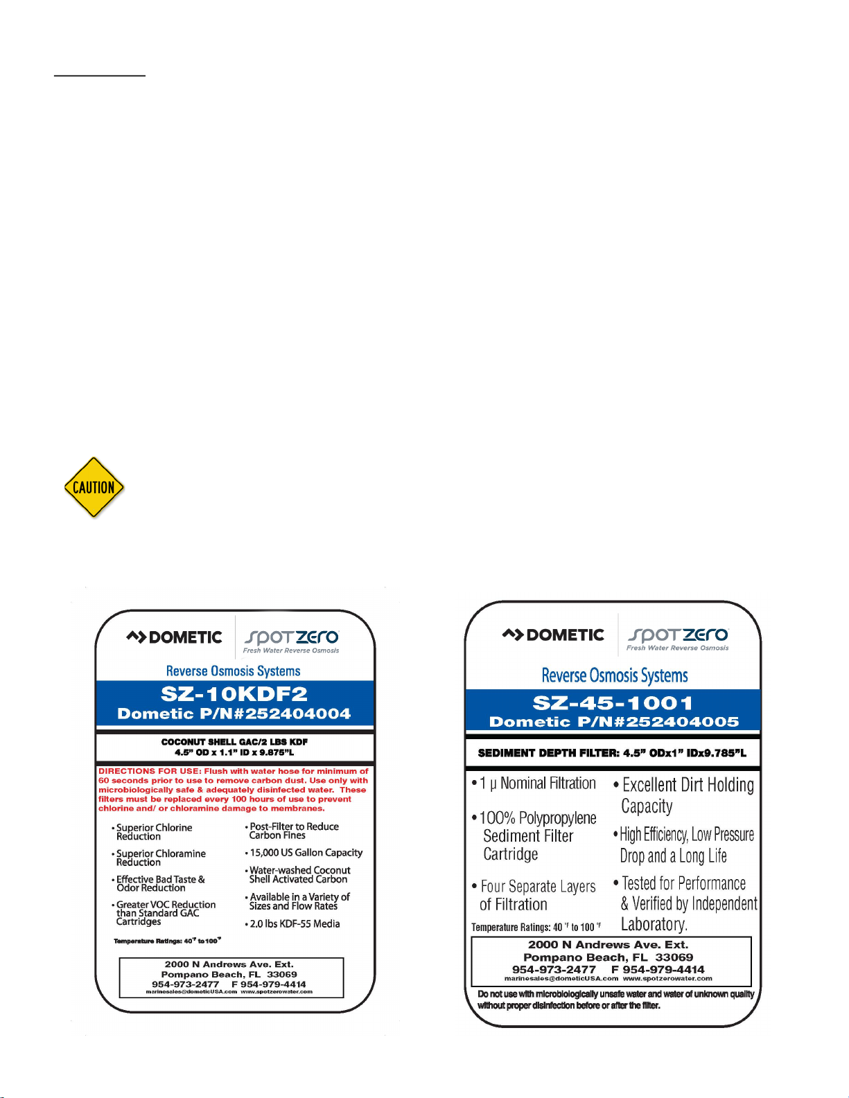
Spot Zero™ systems are supplied with a 1 micron sediment pre-lter (part # 252404005) that lters out most
parcles over 1 microns, a GAC/KDF (part # 252404004) Cartridge that removes chlorine, chloramine, VOCs
and heavy metals. CAUTION: a tradional carbon block lter must not be used as it will not remove chloramines and will cause permanent membrane damage. Pre Filters should be changed every 100 hours and/or
whenever there is a pressure dierence of 15 psi or more between the pressure readings before and aer
the lter. The pump must NEVER be run dry. Operang the pump without sucient feed water will damage
the pump. ALWAYS feed the pump with ltered water. The pump is suscepble to damage from sediment
and debris.
NOTE: THE SZ10KDF2 CARTRIDGE MUST BE FLUSHED OUTSIDE OF SYSTEM BEFORE OPERATING TO REMOVE
CARBON DUST. You can head to www.spotzero.com/support to see demo videos. Do not
aempt to clean used lter cartridges. The SZ10KDF2 is rated to absorb chlorine, chloramine, heavy metals,
etc. up to 18,000 gallons of feed water, which is the equivalent to approximately 100 hours of run me.
CAUTION: If the pre-lter becomes clogged and the water ow to the pump is reduced or
interrupted, cavitaon will occur. This will damage the pump.
6

ACRONYMS AND DEFINITIONS
ACRONYM/SYMBOLS DEFINITION
FWF FRESH WATER FLUSH
RO REVERSE OSMOSIS
PSI POUNDS PER SQUARE INCH
GPM GALLONS PER MINUTE
GPD GALLONS PER DAY
TDS TOTAL DISSOLVED SOLIDS
PPM PARTS PER MILLION
TCF TEMPERATURE CORRECTION FACTOR
LP SWITCH LOW PRESSURE SWITCH
HP SWITCH HIGH PRESSURE SWITCH
Φ PHASE
SW SEA WATER
FW FRESH WATER
7
PRINCIPLES OF REVERSE OSMOSIS
REVERSE OSMOSIS
How Fresh Water Is Produced
Reverse Osmosis or “RO” is a process where freshwater water is produced by pumping saltwater
through a semi-permeable membrane.
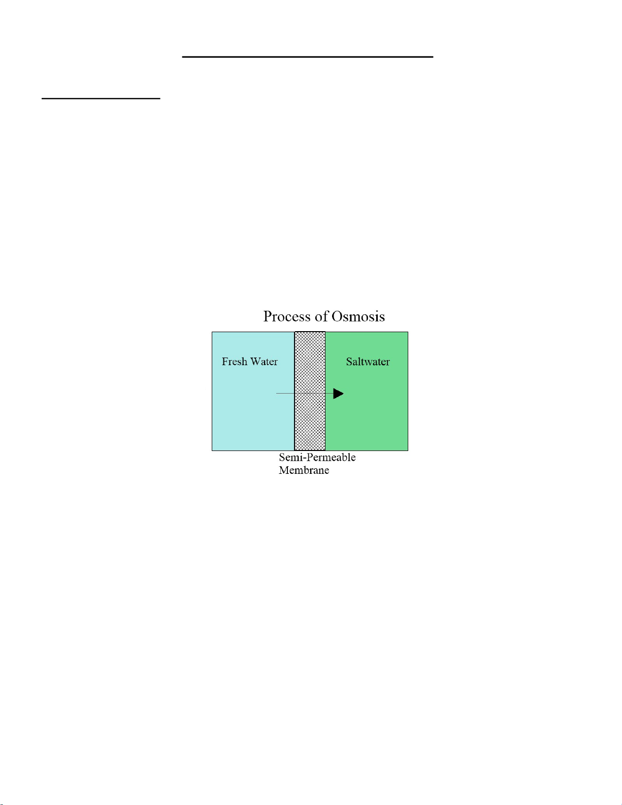
Osmosis
Osmosis is a naturally occurring process where a weak solution will cross a semi-permeable membrane to mix with a highly concentrated solution. For example a freshwater solution will naturally
want to mix with a saltwater solution.
Reverse Osmosis
To reverse this process work is put into the system using a pump. The pump causes pressure to
build up on the saltwater side of the membrane. This pressure forces water across the semipermeable membrane. The membrane is designed to allow the water molecules to pass while
preventing the salt and other solids from doing so. Fresh water is collected on the other side of
the membrane as a result.
8

UNIT SPECIFICATIONS
ZTC MODEL 2000
FW Configuration
(Spot Zero)
Feed Water Source
Rated Production Dock
Water –gpd(ldp)
Rejection and Flow Rates
FW Nominal TDSRejec-
tion % (Spot Zero)
FW Minimum
Concen-trate Flow
gpm (lpm)
Connections
FW Feed inch
(Spot Zero)
Product inch 3/8” QC 9.5mm 3/8” QC 9.5mm
Concentrate inch 1/2” QC 12.7mm 1/2” QC 12.7mm
Membranes
1 Vessel 2 Vessels
Fresh Water Fresh Water
2000(7571) 3000(11356)
95% 95%
1 (3.7) 1(3.7)
1/2” 1/2”
3000
FW Membrane Per
Vessel
FW Membrane Size 4039 4039
Pumps
FW Pressure Pump
Type
FW RO Motor amps 5.1 5.1
Electrical
Voltage
Weight lb. (kg)
1 1
Vane Vane
230V 50/60Hz 1Φ 230V 50/60Hz 1Φ
108(49) 108(49)
9

2. INSTALLATION AND COMMISSIONING
10
INSTALLATION PROCEDURE
FEED WATER
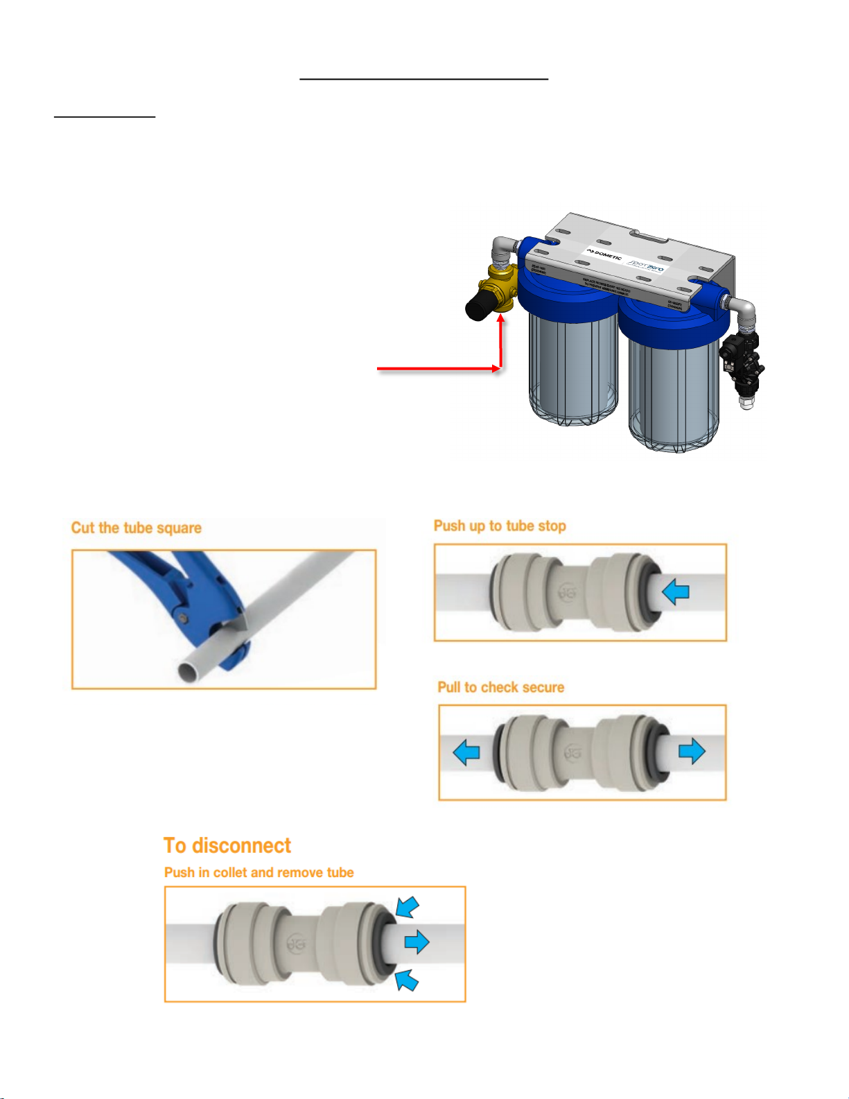
1. Plumb the feed water from the dock into the pre-lter inlet pressure regulator ng. 1/2” FNPT or 1”
MNPT custom connecon from customer.
Feed from dock
2. Tube cung and installaon procedure.
Cut the tube square and remove burrs and sharp edges. Ensure the outside diameter is free of score
marks. For so or thin walled tube we recommend
the use of a tube insert.
Push the tube into the ng, to the tube stop.
11
To disconnect, ensure the system
is depressurized, push the collet
square against the ng. With the
collet held in this posion the tube
can be removed.
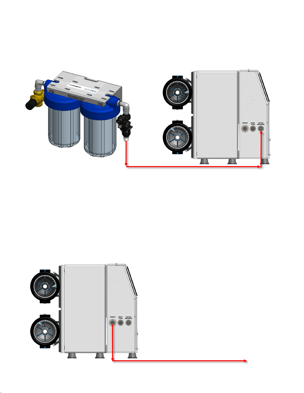
3. From the pre- lter outlet ng, run the white nylon 1/2” Spot Zero water tubing to the feed from
pre-ltraon ng.
1/2” Tube
4. From the “Overboard” discharge ng, run the white nylon 1/2” Spot Zero water tubing to a
dedicated overboard ng. Water must be allowed to run freely, without any restricons or blockage
in the brine discharge line. Be sure that no back pressure exists in the “Overboard” discharge line.
Note: There is an internal check valve in the brine discharge line in the system.
12
1/2” Tube
To overboard
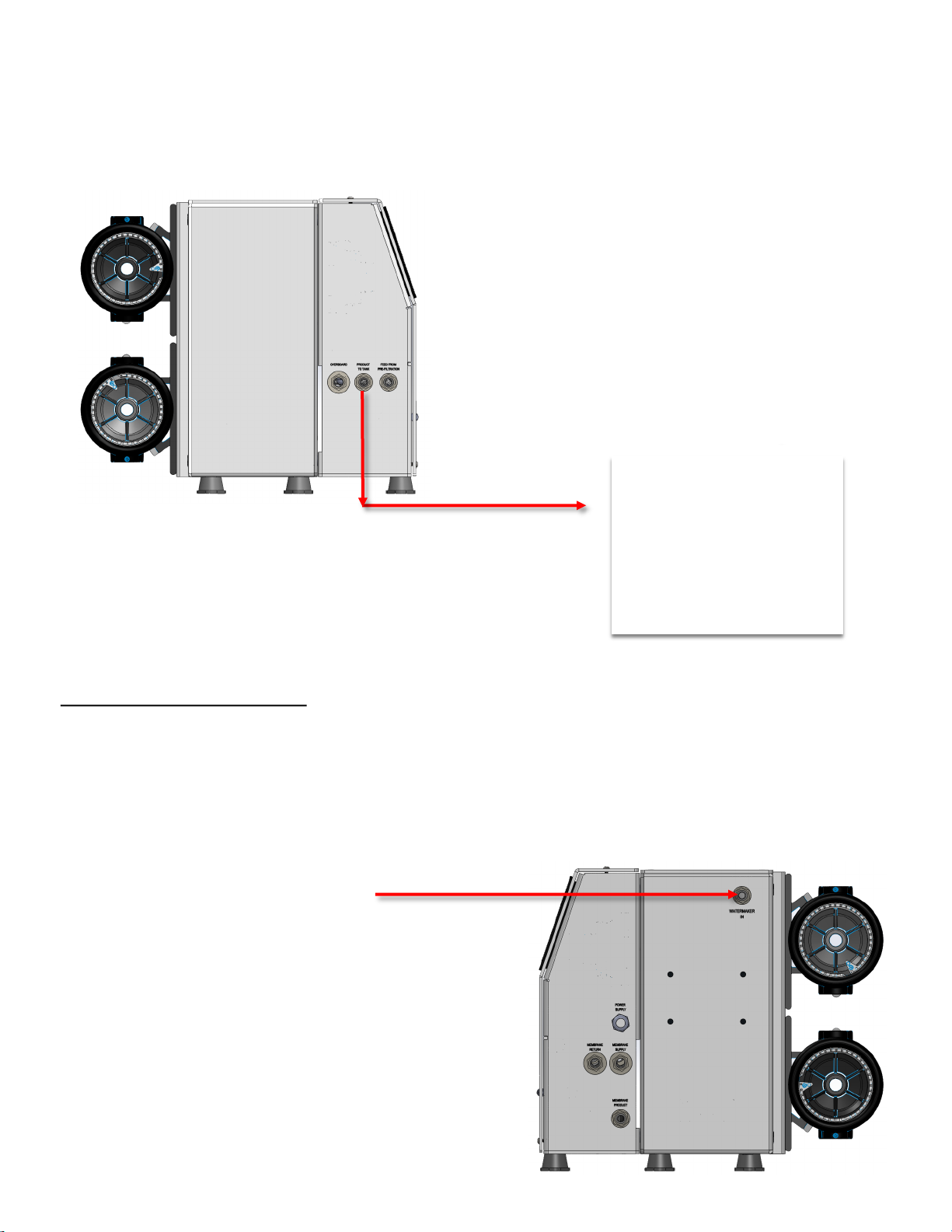
5. From the product to tank ng, run the white nylon 3/8” Spot Zero water tubing to the vessels fresh
water tank.
3/8” Tube
Ship’s fresh
water tank
FEED FROM WATERMAKER
1. Connect the 3/8” product line from the water maker to the “WATER MAKER IN” ng. Always install a
three way valve in line with this, so the water can be diverted to the spot zero system, or to the vessels
fresh water tank.
From water maker
3/8” Tube
13
Electrical Connecons
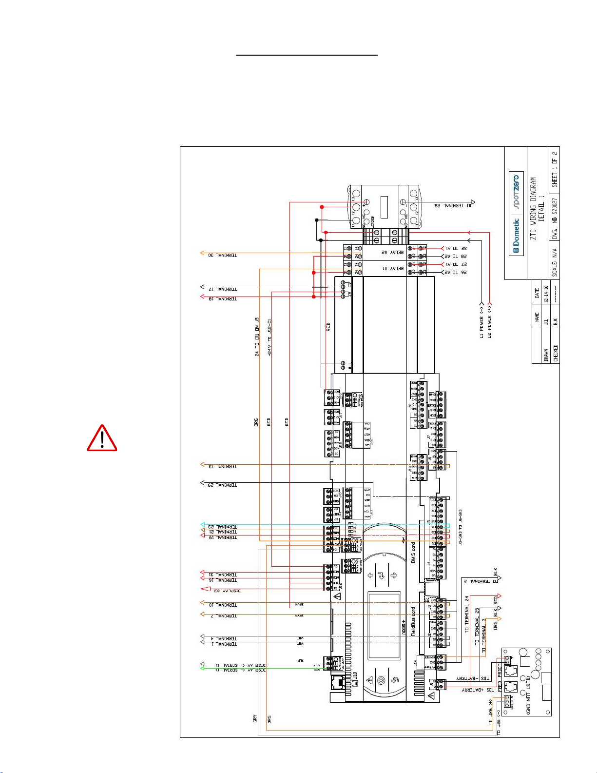
1. Supply and connect specied power (115v or 230v) from the vessels panel to the ZTC panel. Connect line
1 and line 2 to the terminals, and connect the ground wire to the ground bus bar. Be sure to conrm systems rated voltage before applying power. Reference DWG SZ0027.
NOTE: IT’S RECOMMENDED
THAT A QUALIFIED ELECTRICIAN WIRE YOUR SYSTEM IN ACCORDANCE
WITH ABYC REQUIRE-
MENTS.
WARNING: TO REDUCE THE
RISK OF ELECTRICAL
SHOCK, THE INCOMING
POWER SUPPLY MUST INCLUDE A PROTECTIVE
GROUND.
14
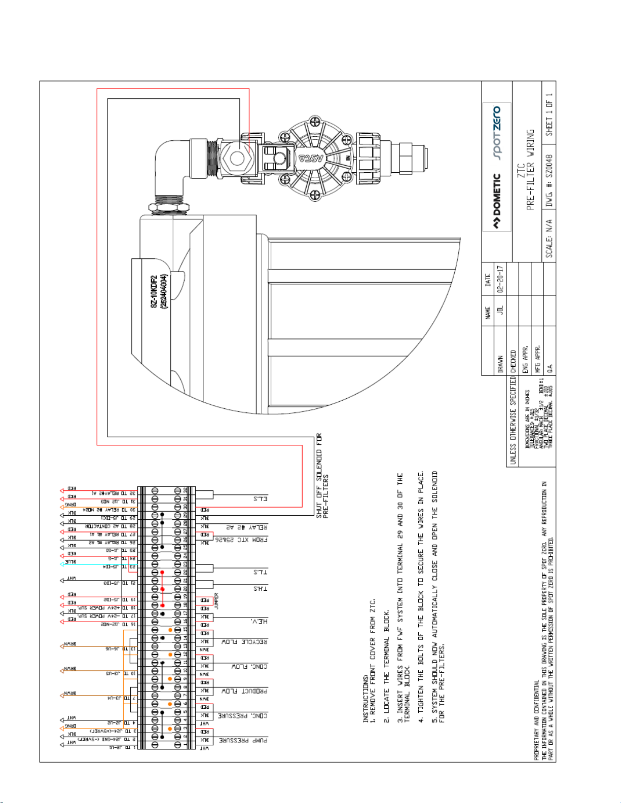
2. Connect the Pre-lter power leads as shown below.
15
S
E
F
S
HE
F
R
BRINE
DISCHARGE
OVERBOARD
D VOLUME MUS T
0.3
RESTRICTOR
PRODUCT
TANK
PRODUCT TO
SHIP
WAT
DOCK
FEED FROM
TAP WATER
FS
LEGEND
CHECK VALVE
NEEDLE VALVE
SOLENOID VALVE
SOLENOID VALVE
FR
XX
FLOW SENSOR
FLOW RESTRICTOR
SYPHON BREAK
FEED FROM
WATERMAKER
(DESALINATOR)*
1/2"
1/2"
1/2" NPT
TUBE SIZE
1/2"
1/2"
3/8"
1/2"
1/2"
3/8"
SHEET 1 OF 1
J
ZTC
F
DWG. #: SZ0032
L
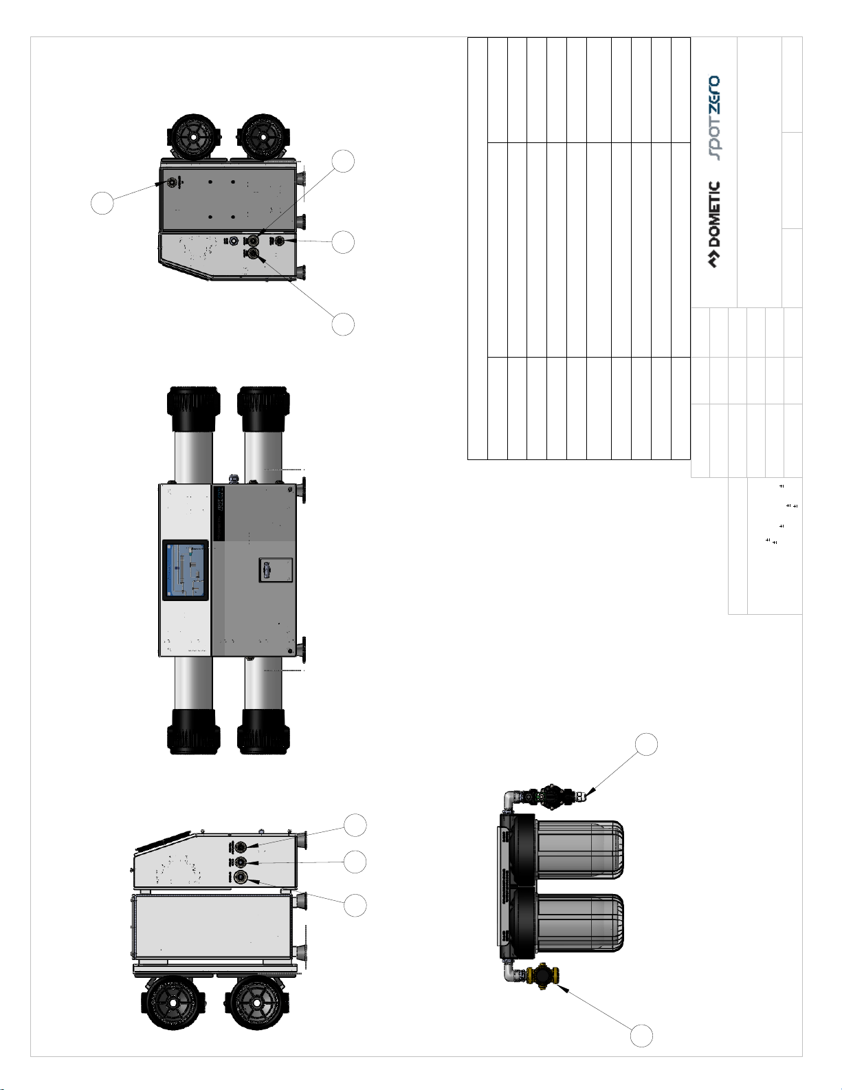
TO ZTC TANK
DESCRIPTION
INLETS & OUTLETS
K
FEED FROM DOCK
FEED FROM PRE FILTER
B
A
C
WATERMAKER IN
VENT/OUTBOARD
E
PRODUCT TO TANK
MEMBRANE SUPPLY
MEMBRANE RETURN
F
J
K
H
MEMBRANE PRODUCT
DATE
NAME
L
INLET & OUTLET LOCATIONS
SCALE: 1:10
04-17-17
JIL
LOCATION
MFG APPR.
ENG APPR.
1
.010
1/2 BEND
.015
1/32
Q.A.
.005
CHECKED
DRAWN
C
H
E
PRE-FILTERS
A
ANGULAR: MACH
TWO PLACE DECIMAL
DIMENSIONS ARE IN INCHES
TOLERANCES:
THREE PLACE DECIMAL
FRACTIONAL
UNLESS OTHERWISE SPECIFIED:
1. SOME PARTS REMOVED IN ORDER
TO MAKE VISUALS MORE CLEAR.
NOTES:
B
PROPRIETARY AND CONFIDENTIAL
THE INFORMATION CONTAINED IN THIS DRAWING IS THE SOLE PROPERTY OF SPOT ZERO. ANY REPRODUCTION IN
PART OR AS A WHOLE WITHOUT THE WRITTEN PERMISSION OF SPOT ZERO IS PROHIBITED.
 Loading...