

Dometic SMP301-02, SMP301-03 Installation And Operating Manual
ENDEFR
ES
IT
NL
NO
ENERGY & LIGHTING
ACCESSORIES
SMP301-02, SMP301-03
Power supply unit
Installation and Operating Manual. . . . . . . .6
Schaltnetzteil
Montage- und Bedienungsanleitung . . . . .20
Bloc d'alimentation
Instructions de montage
et de service . . . . . . . . . . . . . . . . . . . . . . . . .34
Fuente conmutada
Instrucciones de montaje y de uso. . . . . . .48
Alimentatore a commutazione
Istruzioni di montaggio e d’uso . . . . . . . . .62
Voeding
Montagehandleiding en
gebruiksaanwijzing . . . . . . . . . . . . . . . . . . .76
Koplingsstrømforsyning
Monterings- og bruksanvisning . . . . . . . . .90

SMP301-02/-03
1
2
SMP 301-02
11
1
2345
10
89
67
SMP 301-03
1 2 3 4 5
1112
10
89
67
3
SMP301-02/-03
3
A
B
≥ 200 mm
≥ 200 mm
≥ 200 mm
≥ 50 mm
≥ 200 mm
≥ 100 mm
4
SMP301-02/-03
A
B
1
2
3
4
1
5
5

EN
SMP301-02/-03
Please read this instruction manual carefully before installation and first
use, and store it in a safe place. If you pass on the product to another
person, hand over this instruction manual along with it.
Table of contents
1 Explanation of symbols. . . . . . . . . . . . . . . . . . . . . . . . . . . . . . . . . . . . . . . . . . .7
2 Safety instructions . . . . . . . . . . . . . . . . . . . . . . . . . . . . . . . . . . . . . . . . . . . . . . .7
3 Scope of delivery . . . . . . . . . . . . . . . . . . . . . . . . . . . . . . . . . . . . . . . . . . . . . . .9
4 Intended use . . . . . . . . . . . . . . . . . . . . . . . . . . . . . . . . . . . . . . . . . . . . . . . . . .10
5 Technical description . . . . . . . . . . . . . . . . . . . . . . . . . . . . . . . . . . . . . . . . . . .10
6 Installing the power supply unit . . . . . . . . . . . . . . . . . . . . . . . . . . . . . . . . . . .13
7 Using the power supply unit. . . . . . . . . . . . . . . . . . . . . . . . . . . . . . . . . . . . . .16
8 Maintaining and cleaning the power supply unit . . . . . . . . . . . . . . . . . . . . .17
9 Troubleshooting . . . . . . . . . . . . . . . . . . . . . . . . . . . . . . . . . . . . . . . . . . . . . . .18
10 Warranty . . . . . . . . . . . . . . . . . . . . . . . . . . . . . . . . . . . . . . . . . . . . . . . . . . . . .18
11 Disposal . . . . . . . . . . . . . . . . . . . . . . . . . . . . . . . . . . . . . . . . . . . . . . . . . . . . . .19
12 Technical data . . . . . . . . . . . . . . . . . . . . . . . . . . . . . . . . . . . . . . . . . . . . . . . . .19
6

EN
SMP301-02/-03 Explanation of symbols
1 Explanation of symbols
DANGER!
D
!
Safety instruction: Failure to observe this instruction will cause fatal or
serious injury.
WARNING!
Safety instruction: Failure to observe this instruction can cause fatal or
serious injury.
CAUTION!
Safety instruction: Failure to observe this instruction can lead to injury.
!
NOTICE!
A
Failure to observe this instruction can cause material damage and impair
the function of the product.
NOTE
Supplementary information for operating the product.
I
2 Safety instructions
The manufacturer accepts no liability for damage in the following cases:
• Faulty assembly or connection
• Damage to the product resulting from mechanical influences and excess voltage
• Alterations to the product without express permission from the manufacturer
• Use for purposes other than those described in the operating manual
7

EN
Safety instructions SMP301-02/-03
2.1 General safety
WARNING!
!
2.2 Safety when installing the product
• This product can be used by children aged 8 years or over, as well as
by persons with diminished physical, sensory or mental capacities or a
lack of experience and knowledge, provided they are supervised, or
have been taught how to use the device safely and are aware of the
resulting risks.
• Cleaning and user maintenance must not be carried out by unsupervised children.
• Only use the product as intended.
• Do not use the product in wet or damp environments or in areas
where there is a risk of gas or dust explosions.
• Maintenance and repair work may only be carried out by qualified personnel who are familiar with the risks involved and the relevant regulations.
WARNING!
!
A
• The electrical installation may only be connected by qualified person-
nel and only in accordance with the national regulations. Incorrect
connection may cause severe hazards.
• Take the precautions necessary to ensure that children cannot interfere with the product.
Dangerous situations may occur which cannot be recognised by
children!
NOTICE!
• Do not expose the product to any heat source (such as direct sunlight
or heating). Avoid additional heating of the device in this way.
8

EN
SMP301-02/-03 Scope of delivery
Electrical cables
CAUTION!
!
• Lay the cables so that they cannot be tripped over or damaged.
• Have damaged power cables replaced by a specialist in accordance
with national regulations.
NOTICE!
A
2.3 Operating the product safely
!
• If cables have to be fed through metal walls or other walls with sharp
edges, use ducts or bushings to prevent damage.
• Do not lay cables which are loose or bent next to electrically conductive material (metal).
• Do not pull on the cables.
• Do not lay the AC cable and the DC cable in the same duct.
• Fasten the cables securely.
WARNING!
• Operate the product only if you are certain that the casing and the
cables are undamaged.
• Always disconnect the power supply when working on the product.
NOTICE!
• Make sure the ventilation grilles in the product are not covered.
A
• Ensure good ventilation.
3Scope of delivery
• Power supply unit
• Installation and operating manual
9

EN
Intended use SMP301-02/-03
4 Intended use
The power supply unit type SMP301-02/-03 is intended for installation in recreational vehicles used as accommodation (e.g. motor homes, caravans, boats etc.).
The power supply unit is used as the voltage supply for DC consumer units, and can
be supplied with AC or DC power.
The power supply unit is approved for continuous operation.
5 Technical description
The power supply unit can be connected to an external power supply.
SMP301-03 only
The power supply unit can be connected to a battery.
The integrated priority circuit automatically switches over from battery operation to
mains operation when an external power supply is available.
In mains operation, the power supply unit supplies consumer units with a constant
DC of 12.7 V. The battery is automatically disconnected from the consumer units.
Battery operation is activated automatically if mains operation is deactivated. The
consumer units connected are supplied with energy via the battery.
10
EN
SMP301-02/-03 Technical description
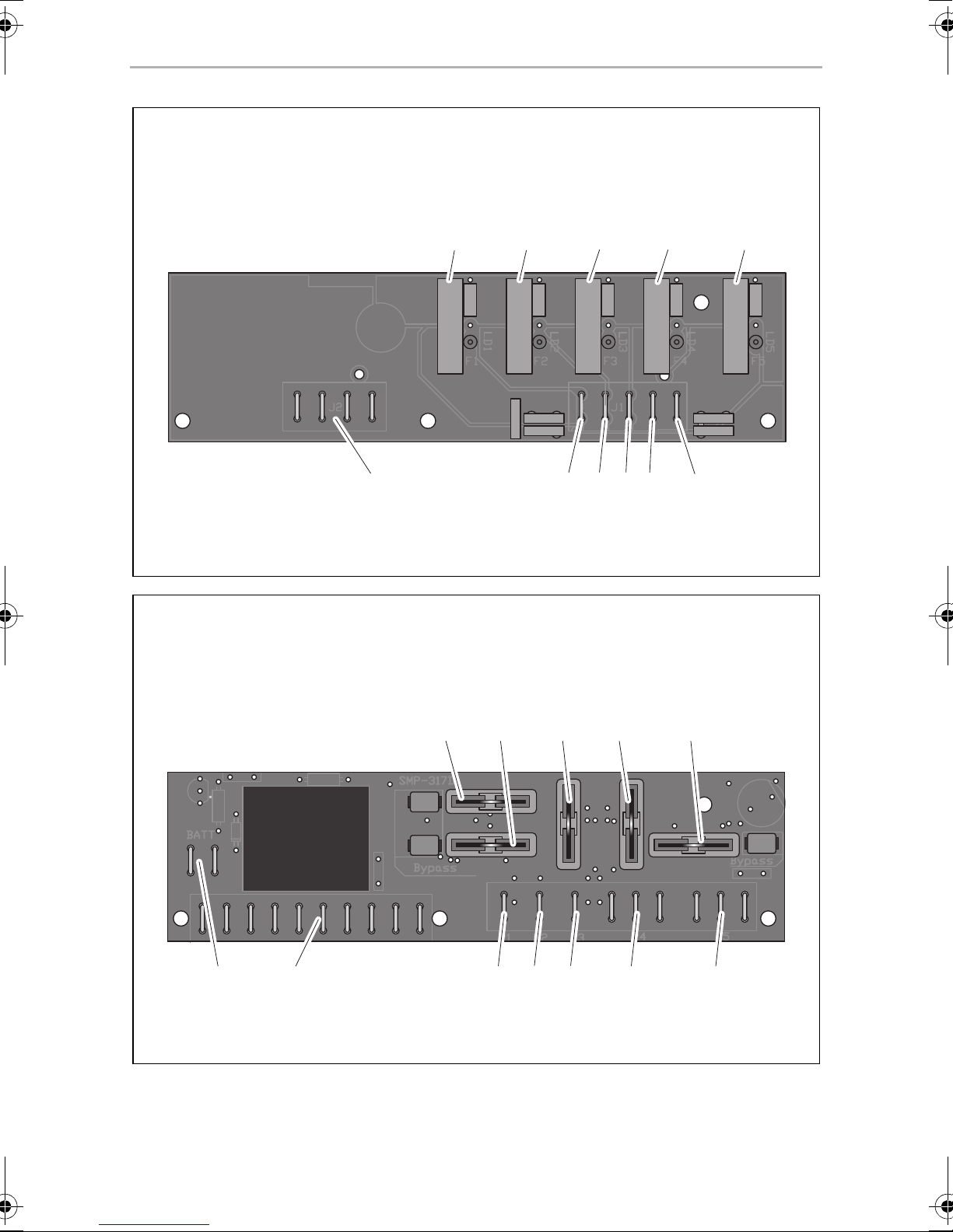
5.1 Connections and displays
SMP301-02
No. in
fig. 1, page 3
1 Plug-in fuse F1 for output group 1 (maximum 15 A)
2 Plug-in fuse F2 for output group 2 (maximum 15 A)
3 Plug-in fuse F3 for output group 3 (maximum 15 A)
4 Plug-in fuse F4 for output group 4 (maximum 15 A)
5 Plug-in fuse F5 for output group 5 (maximum 15 A)
6 Flat plug P5 6.3 mm for group 5
7 Flat plug P4 6.3 mm for group 4
8 Flat plug P3 6.3 mm for group 3
9 Flat plug P2 6.3 mm for group 2
10 Flat plug P1 6.3 mm for group 1
11 4x flat plug P7 6.3 mm common earth connection
Element
11
EN
Technical description SMP301-02/-03
SMP 301-03
No. in
fig. 2, page 3
1 Plug-in fuse F1 for output group 1 (maximum 10 A)
2 Plug-in fuse F2 for output group 2 (maximum 10 A)
3 Plug-in fuse F3 for output group 3 (maximum 5 A)
4 Plug-in fuse F4 for output group 4 (maximum 5 A)
5 Plug-in fuse F5 for output group 5 (maximum 10 A)
6 3x flat plug P5 6.3 mm for group 5
7 3x flat plug P4 6.3 mm for group 4
8 Flat plug P3 6.3 mm for group 3
9 Flat plug P2 6.3 mm for group 2
10 Flat plug P1 6.3 mm for group 1
11 10x flat plug P7 6.3 mm battery terminal / common earth connection
12 2x flat plug P6 for positive terminal battery
Element
12

EN
SMP301-02/-03 Installing the power supply unit
6 Installing the power supply unit
6.1 Fastening the power supply unit
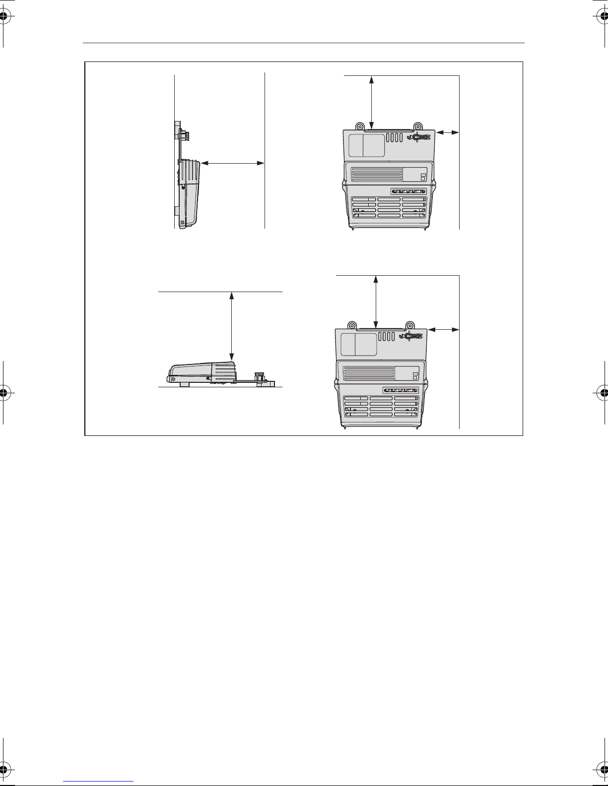
When selecting the installation location, observe the following instructions:
• The power supply unit must be installed vertically on a wall (maximum ambient
temperature 50 °C) or horizontally on the ground or on a pedestal (maximum
ambient temperature 40 °C and maximum load 75 %).
• The optimum installation position is vertically on a wall.
• The power supply unit must be installed in a location that is protected from
moisture.
• The power supply unit must not be installed in areas with easily flammable
materials (e.g. gas cylinder lockers).
• The power supply unit must not be installed in a dusty environment.
• The place of installation must be well ventilated. A ventilation system must be
available for installations in small, enclosed spaces. Please observe the minimum
clearance around the power supply unit (fig. 3, page 4).
• There must be free space in front of the ventilation grills.
• When ambient temperatures are higher than those stated above (such as in
engine or heating compartments, or when exposed to direct sunlight), the heat
produced by the power supply unit when under load can lead to automatic
shutdown.
• The installation area must be a level and sufficiently sturdy surface.
NOTICE!
A
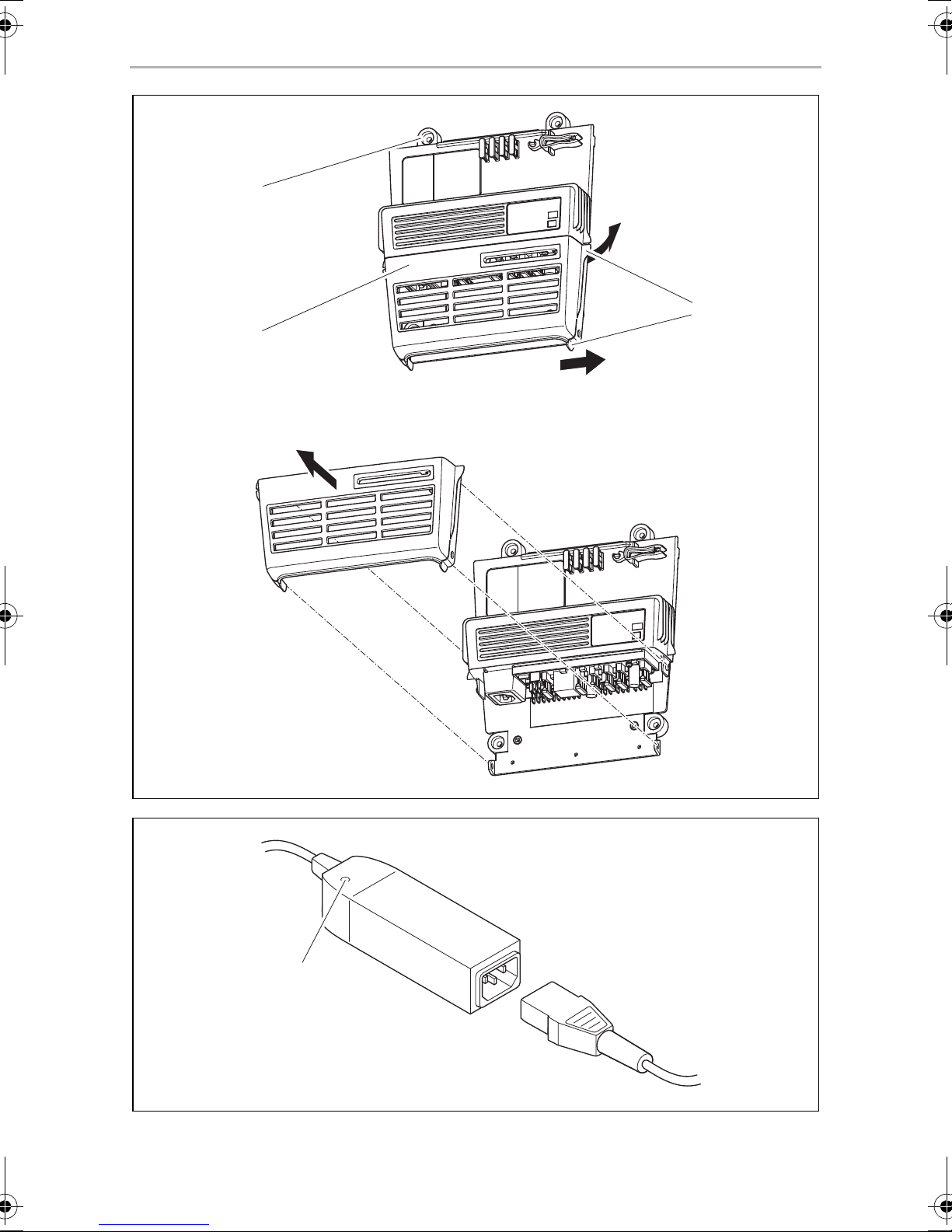
Fasten the power supply unit as follows:
➤ Screw one screw through each of the four bore holes in the four fastening tabs
(fig. 4 3, page 5).
Before drilling any holes, make sure that no electrical cables or other
parts of the vehicle can be damaged by drilling, sawing and filing.
13
EN
Installing the power supply unit SMP301-02/-03
6.2 Connecting the power supply unit
SMP 301-02
Please note that flat plugs P1 – P5 are individually fused via plug-in fuses F1 – F5 in the
following manner:
Flat plug Fuse Fuse assignment
P1 F1 15 A 15 A
P2 F2 15 A 15 A
P3 F3 15 A 15 A
P4 F4 15 A 15 A
P5 F5 15 A 15 A
Maximum permissible
current
➤ Press the two tabs (fig. 4 1, page 5) in the direction indicated by the arrows and
lift the cover off (fig. 4 2, page 5).
➤ Connect the positive terminal of the consumer units to the flat plugs P1 – P5
(fig. 1 6–10, page3).
➤ Connect the negative terminal of the consumer units to one of the flat plugs P7
(any pin) (fig. 1 11, page 3).
➤ Connect the AC connection cable to the AC plug.
➤ Secure all cables with strain relief clamps.
14

EN
SMP301-02/-03 Installing the power supply unit
SMP 301-03
Please note that flat plugs P1 – P5 are individually fused via plug-in fuses F1 – F5 in the
following manner:
Flat plug Fuse Fuse assignment
P1 F1 10 A 15 A
P2 F2 10 A 15 A
P3 F3 5 A 15 A
P4 F4 5 A 15 A
P5 F5 10 A 15 A
Maximum permissible
current
➤ Press the two tabs (fig. 4 1, page 5) in the direction indicated by the arrows and
lift the cover off (fig. 4 2, page 5).
➤ Connect the positive terminal of the consumer units to the flat plugs P1 – P5
(fig. 2 6–10, page3).
➤ Connect the negative terminal of the consumer units to one of the flat plugs P7
(any pin) (fig. 2 11, page 3).
➤ Connect the positive terminal of the battery to one of the flat plugs P6 (fig. 2 12,
page 3).
➤ Connect the negative terminal of the battery to one of the flat plugs P7 (any pin)
(fig. 2 11, page 3).
➤ Connect the AC connection cable to the AC plug.
➤ Ensure that the cable length between the battery and the power supply unit is not
more than 2 m.
➤ Secure all cables with strain relief clamps.
15

EN
Using the power supply unit SMP301-02/-03
7 Using the power supply unit
The power supply unit switches on as soon as an external power supply is available.
Only replace a plug-in fuse which has blown (1 – 5 in fig. 1, page 3 to fig. 2,
page 3) with a plug-in fuse of equivalent quality.
Please contact the manufacturer's branch in your country (see the back of the instruction manual for the addresses) or your retailer if the function cannot be restored by
switching on the fuses or replacing the plug-in fuse.
7.1 Using the surge protector (optional)
The optional surge protector (ref. no. 9106505815) is connected on the supply side
of the power supply unit. The surge protector disconnects the power supply line if
the input voltage exceeds approx. 270 V.
➤ Check whether the red LED (fig. 5 1, page 5) lights up.
✓ If the red LED lights up, this indicates that a voltage surge has occurred.
➤ Wait 20 – 30 minutes.
✓ The surge protector resets itself automatically as soon as the voltage returns to a
permissible value. Once the voltage has reached a permissible value, the red LED
remains lit up for 20 – 30 minutes.
16

EN
SMP301-02/-03 Maintaining and cleaning the power supply unit
7.2 Replacing the plug-in fuses
NOTE
I
➤ Disconnect all consumer units from the power supply unit.
➤ Disconnect the power supply unit from the power supply.
➤ Press the two tabs (fig. 4 1, page 5) in the direction indicated by the arrows and
lift the cover off (fig. 4 2, page 5).
➤ Only replace plug-in fuses which have blown with new plug-in fuses of the type
“ATO Type – LITTLEFUSE” and the same rating.
➤ Re-attach the cover to the power supply unit.
The positioning of the plug-in fuses is used to configure manufacturerspecific functions.
When replacing a plug-in fuse, take care to fit the replacement in the
same place. Malfunctions may occur otherwise.
➤ Put the power supply unit back into operation.
➤ If the plug-in fuse is tripped again, please contact the manufacturer's branch in
your country (see the back of the instruction manual for the addresses) or your
retailer.
8 Maintaining and cleaning the power
supply unit
NOTICE!
A
➤ Clean the power supply unit using a damp cloth as required.
Do not use any sharp or hard objects for cleaning since they may
damage the device.
17
EN
Troubleshooting SMP301-02/-03
9 Troubleshooting
Fault Cause Remedy
No power from
12 V outputs
when unit is
operating in
mains supply
mode.
No power from
12 V outputs
when unit is
operating in
battery mode.
The plug-in fuse of the related 12 V
output (e.g. fig. 1 1, page 3) is defective. The red LED next to the plug-in
fuse lights up.
The power supply unit has switched off
as a result of the surge protector. The
red LED (fig. 5 1, page 5) lights up.
The plug-in fuse of the related 12 V
output (e.g. fig. 1 1, page 3) is defective. The red LED next to the plug-in
fuse lights up.
The battery has been connected
incorrectly.
Replace it with a plug-in fuse of
equivalent quality.
The surge protector resets itself
automatically as soon as the
voltage returns to a permissible
value. If this is not the case,
contact a specialist electrician.
Replace it with a plug-in fuse of
equivalent quality.
Connect the battery correctly
(chapter “Connecting the power
supply unit” on page 14).
Contact an electrician,
if applicable.
10 Warranty
The statutory warranty period applies. If the product is defective, please contact the
manufacturer's branch in your country (see the back of the instruction manual for the
addresses) or your retailer.
For repair and guarantee processing, please include the following documents when
you send in the device:
• A copy of the receipt with purchasing date
• A reason for the claim or description of the fault
18
EN
SMP301-02/-03 Disposal
11 Disposal
➤ Place the packaging material in the appropriate recycling waste bins wherever
possible.
If you wish to finally dispose of the product, ask your local recycling centre
or specialist dealer for details about how to do this in accordance with the
M
applicable disposal regulations.
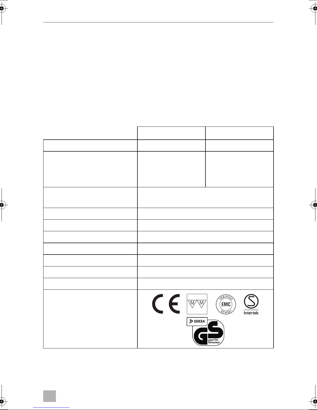
12 Technical data
SMP301-02 SMP301-03
Ref. no.: 9106504643 9106504717
Model: Without relay With relay
All outputs are live when
there is an external 12 V
power supply
Rated input voltage: 230 Vw
12 Vg
Constant output power: 350 W
Output voltage: 12.7 Vg
Amperage: 27 A
Ambient temperature: –10 °C to 40 °C
Housing: Protection class 20
Dimensions (L x W x H): 240 x 207 x 56 mm
Weight: 1 kg
Inspection/certification:
19

DE
SMP301-02/-03
Bitte lesen Sie diese Anleitung vor Einbau und Inbetriebnahme sorgfältig
durch und bewahren Sie sie auf. Geben Sie sie im Falle einer Weitergabe
des Produktes an den Nutzer weiter.
Inhaltsverzeichnis
1 Erläuterung der Symbole . . . . . . . . . . . . . . . . . . . . . . . . . . . . . . . . . . . . . . . .21
2 Sicherheitshinweise . . . . . . . . . . . . . . . . . . . . . . . . . . . . . . . . . . . . . . . . . . . .21
3 Lieferumfang . . . . . . . . . . . . . . . . . . . . . . . . . . . . . . . . . . . . . . . . . . . . . . . . . 24
4 Bestimmungsgemäßer Gebrauch . . . . . . . . . . . . . . . . . . . . . . . . . . . . . . . . 24
5 Technische Beschreibung . . . . . . . . . . . . . . . . . . . . . . . . . . . . . . . . . . . . . . 24
6 Schaltnetzteil montieren . . . . . . . . . . . . . . . . . . . . . . . . . . . . . . . . . . . . . . . . 27
7 Schaltnetzteil benutzen . . . . . . . . . . . . . . . . . . . . . . . . . . . . . . . . . . . . . . . . 30
8 Schaltnetzteil pflegen und reinigen . . . . . . . . . . . . . . . . . . . . . . . . . . . . . . . .31
9 Fehlerbeseitigung. . . . . . . . . . . . . . . . . . . . . . . . . . . . . . . . . . . . . . . . . . . . . 32
10 Gewährleistung. . . . . . . . . . . . . . . . . . . . . . . . . . . . . . . . . . . . . . . . . . . . . . . 32
11 Entsorgung . . . . . . . . . . . . . . . . . . . . . . . . . . . . . . . . . . . . . . . . . . . . . . . . . . 33
12 Technische Daten . . . . . . . . . . . . . . . . . . . . . . . . . . . . . . . . . . . . . . . . . . . . . 33
20
DE
SMP301-02/-03 Erläuterung der Symbole
1 Erläuterung der Symbole
GEFAHR!
D
!
Sicherheitshinweis: Nichtbeachtung führt zu Tod oder schwerer
Verletzung.
WARNUNG!
Sicherheitshinweis: Nichtbeachtung kann zu Tod oder schwerer
Verletzung führen.
VORSICHT!
Sicherheitshinweis: Nichtbeachtung kann zu Verletzungen führen.
!
ACHTUNG!
A
Nichtbeachtung kann zu Materialschäden führen und die Funktion des
Produktes beeinträchtigen.
HINWEIS
Ergänzende Informationen zur Bedienung des Produktes.
I
2 Sicherheitshinweise
Der Hersteller übernimmt in folgenden Fällen keine Haftung für Schäden:
• Montage- oder Anschlussfehler
• Beschädigungen am Produkt durch mechanische Einflüsse und Über-
spannungen
• Veränderungen am Produkt ohne ausdrückliche Genehmigung vom Hersteller
• Verwendung für andere als die in der Anleitung beschriebenen Zwecke
21

DE
Sicherheitshinweise SMP301-02/-03
2.1 Grundlegende Sicherheit
WARNUNG!
!
• Dieses Produkt kann von Kindern ab 8 Jahren und darüber sowie von
Personen mit verringerten physischen, sensorischen oder mentalen
Fähigkeiten oder Mangel an Erfahrung und Wissen benutzt werden,
wenn sie beaufsichtigt oder bezüglich des sicheren Gebrauchs des
Gerätes unterwiesen wurden und die daraus resultierenden Gefahren
verstehen.
• Reinigung und Benutzer-Wartung dürfen nicht von Kindern ohne
Beaufsichtigung durchgeführt werden.
• Benutzen Sie das Produkt nur zu seinem bestimmungsgemäßen
Gebrauch.
• Betreiben Sie das Produkt nicht in feuchter oder nasser Umgebung
oder in Bereichen, in denen Gefahr durch Gas- oder Staubexplosion
besteht.
• Die Wartung und Reparatur darf nur durch eine Fachkraft geschehen,
die mit den damit verbundenen Gefahren bzw. einschlägigen Vorschriften vertraut ist.
2.2 Sicherheit bei der Installation des Produkts
WARNUNG!
!
A
• Die elektrische Installation darf nur von einer Fachkraft nach den natio-
nalen Vorschriften angeschlossen werden. Durch unsachgemäßes
Anschließen können erhebliche Gefahren entstehen.
• Sichern Sie das Produkt so, dass Kinder keinen Zugriff darauf haben.
Es können Gefahren entstehen, die von Kindern nicht erkannt
werden!
ACHTUNG!
• Setzen Sie das Produkt keiner Wärmequelle (Sonneneinstrahlung,
Heizung usw.) aus. Vermeiden Sie so zusätzliche Erwärmung des
Gerätes.
22

DE
SMP301-02/-03 Sicherheitshinweise
Elektrische Leitungen
VORSICHT!
!
A
2.3 Sicherheit beim Betrieb des Produkts
• Verlegen Sie die Leitungen so, dass keine Stolpergefahr entsteht und
eine Beschädigung des Kabels ausgeschlossen ist.
• Lassen Sie ein beschädigtes Stromkabel von einer Fachkraft nach den
nationalen Vorschriften austauschen.
ACHTUNG!
• Müssen Leitungen durch Blechwände oder andere scharfkantige
Wände geführt werden, dann benutzen Sie Leerrohre bzw.
Leitungsdurchführungen.
• Verlegen Sie Leitungen nicht lose oder scharf abgeknickt an elektrisch
leitenden Materialien (Metall).
• Ziehen Sie nicht an Leitungen.
• Verlegen Sie Wechselstromleitung und Gleichstromleitung nicht
zusammen im gleichen Leitungskanal (Leerrohr).
• Befestigen Sie die Leitungen gut.
!
A
WARNUNG!
• Betreiben Sie das Produkt nur, wenn das Gehäuse und die Leitungen
unbeschädigt sind.
• Unterbrechen Sie bei Arbeiten am Produkt immer die Stromversorgung.
ACHTUNG!
• Achten Sie darauf, dass die Belüftungsschlitze des Produkts nicht verdeckt werden.
• Achten Sie auf gute Belüftung.
23

DE
Lieferumfang SMP301-02/-03
3 Lieferumfang
• Schaltnetzteil
• Montage- und Bedienungsanleitung
4 Bestimmungsgemäßer Gebrauch
Das Schaltnetzteil vom Typ SMP301-02/-03 ist zum Einbau in bewohnbare Freizeitfahrzeuge (z. B. Wohnmobile, Wohnwagen, Booten etc.) vorgesehen. Das Schaltnetzteil dient zur Spannungsversorgung von Gleichstrom-Verbrauchern und kann
mit Wechselstrom oder Gleichstrom versorgt werden.
Das Schaltnetzteil ist für den Dauerbetrieb zugelassen.
5 Technische Beschreibung
Das Schaltnetzteil kann an eine externe Stromversorgung angeschlossen werden.
Nur SMP301-03
Das Schaltnetzteil kann an eine Batterie angeschlossen werden.
Die integrierte Vorrangschaltung schaltet automatisch von Batterie- auf Netzbetrieb
um, wenn eine externe Stromversorgung zur Verfügung steht.
Im Netzbetrieb stellt das Schaltnetzteil eine konstante Gleichspannung von 12,7 V
für Verbraucher zur Verfügung. Die Batterie wird automatisch von den Verbrauchern
getrennt.
Bei deaktiviertem Netzbetrieb wird automatisch der Batteriebetrieb aktiviert. Die
angeschlossenen Verbraucher werden über die Batterie mit Energie versorgt.
24

DE
SMP301-02/-03 Technische Beschreibung
5.1 Anschlüsse und Anzeigen
SMP301-02
Pos. in
Abb. 1, Seite 3
1 Stecksicherung F1 für Ausgang Gruppe 1 (maximal 15 A)
2 Stecksicherung F2 für Ausgang Gruppe 2 (maximal 15 A)
3 Stecksicherung F3 für Ausgang Gruppe 3 (maximal 15 A)
4 Stecksicherung F4 für Ausgang Gruppe 4 (maximal 15 A)
5 Stecksicherung F5 für Ausgang Gruppe 5 (maximal 15 A)
6 Flachstecker P5 6,3 mm für Gruppe 5
7 Flachstecker P4 6,3 mm für Gruppe 4
8 Flachstecker P3 6,3 mm für Gruppe 3
9 Flachstecker P2 6,3 mm für Gruppe 2
10 Flachstecker P1 6,3 mm für Gruppe 1
11 4x Flachstecker P7 6,3 mm gemeinsamer Masseanschluss
Element
25

DE
Technische Beschreibung SMP301-02/-03
SMP301-03
Pos. in
Abb. 2, Seite 3
1 Stecksicherung F1 für Ausgang Gruppe 1 (maximal 10 A)
2 Stecksicherung F2 für Ausgang Gruppe 2 (maximal 10 A)
3 Stecksicherung F3 für Ausgang Gruppe 3 (maximal 5 A)
4 Stecksicherung F4 für Ausgang Gruppe 4 (maximal 5 A)
5 Stecksicherung F5 für Ausgang Gruppe 5 (maximal 10 A)
6 3x Flachstecker P5 6,3 mm für Gruppe 5
7 3x Flachstecker P4 6,3 mm für Gruppe 4
8 Flachstecker P3 6,3 mm für Gruppe 3
9 Flachstecker P2 6,3 mm für Gruppe 2
10 Flachstecker P1 6,3 mm für Gruppe 1
11 10x Flachstecker P7 6,3 mm Batterieanschluss / gemeinsamer
Element
Masseanschluss
12 2x Flachstecker P6 für Pluspol Batterie
26

DE
SMP301-02/-03 Schaltnetzteil montieren
6 Schaltnetzteil montieren
6.1 Schaltnetzteil befestigen
Beachten Sie bei der Wahl des Montageortes folgende Hinweise:
• Das Schaltnetzteil darf senkrecht an einer Wand (maximale Umgebungstemperatur 50 °C) oder waagerecht auf dem Boden oder einem Podest
(maximale Umgebungstemperatur 40 °C und maximale Last 75 %) montiert
werden.
• Die optimale Einbauposition ist senkrecht an einer Wand.
• Das Schaltnetzteil muss an einer vor Feuchtigkeit geschützten Stelle eingebaut
werden.
• Das Schaltnetzteil darf nicht in Umgebungen mit leicht entzündlichen Materialien
(z. B. Gaskasten) eingebaut werden.
• Das Schaltnetzteil darf nicht in staubigen Umgebungen eingebaut werden.
• Der Einbauort muss gut belüftet sein. Bei Installationen in geschlossenen kleinen
Räumen sollte eine Be- und Entlüftung vorhanden sein. Beachten Sie den
Mindestabstand um das Schaltnetzteil (Abb. 3, Seite 4).
• Die Belüftungsschlitze müssen frei bleiben.
• Bei Umgebungstemperaturen, die höher als die oben genannten sind (z. B. in
Motor- oder Heizungsräumen, direkte Sonneneinstrahlung), kann es durch die
Eigenerwärmung des Schaltnetzteils bei Belastung zum automatischen Abschalten kommen.
• Die Montagefläche muss eben sein und eine ausreichende Festigkeit aufweisen.
ACHTUNG!
A
Befestigen Sie das Schaltnetzteil wie folgt:
➤ Schrauben Sie jeweils eine Schraube durch die Bohrung in den vier
Befestigungslaschen (Abb. 4 3, Seite 5).
Bevor Sie irgendwelche Bohrungen vornehmen, stellen Sie sicher,
dass keine elektrischen Kabel oder andere Teile des Fahrzeugs durch
Bohren, Sägen und Feilen beschädigt werden.
27
DE
Schaltnetzteil montieren SMP301-02/-03
6.2 Schaltnetzteil anschließen
SMP 301-02
Beachten Sie, dass die Flachstecker P1 – P5 wie folgt einzeln über die Stecksicherungen F1 – F5 abgesichert sind:
Flach-
stecker
P1 F1 15 A 15 A
P2 F2 15 A 15 A
P3 F3 15 A 15 A
P4 F4 15 A 15 A
P5 F5 15 A 15 A
Sicherung Sicherungsbelegung
maximal zulässige
Stromstärke
➤ Drücken Sie die beiden Laschen (Abb. 4 1, Seite 5) in Pfeilrichtung und heben
Sie die Abdeckung (Abb. 4 2, Seite 5) ab.
➤ Schließen Sie den Pluspol der Verbraucher an die Flachstecker P1 – P5
(Abb. 1 6 – 10, Seite 3) an.
➤ Schließen Sie den Minuspol der Verbraucher an einen der Flachstecker P7
(beliebiger Stift) (Abb. 1 11, Seite 3) an.
➤ Schließen Sie das Wechselstrom-Anschlusskabel an den Wechselstrom-Stecker
an.
➤ Sichern Sie alle Kabel mit Zugentlastungen.
28
DE
SMP301-02/-03 Schaltnetzteil montieren
SMP 301-03
Beachten Sie, dass die Flachstecker P1 – P5 wie folgt einzeln über die Stecksicherungen F1 – F5 abgesichert sind:
Flach-
stecker
P1 F1 10 A 15 A
P2 F2 10 A 15 A
P3 F3 5 A 15 A
P4 F4 5 A 15 A
P5 F5 10 A 15 A
Sicherung Sicherungsbelegung
maximal zulässige
Stromstärke
➤ Drücken Sie die beiden Laschen (Abb. 4 1, Seite 5) in Pfeilrichtung und heben
Sie die Abdeckung (Abb. 4 2, Seite 5) ab.
➤ Schließen Sie den Pluspol der Verbraucher an die Flachstecker P1 – P5
(Abb. 2 6 – 10, Seite 3) an.
➤ Schließen Sie den Minuspol der Verbraucher an einen der Flachstecker P7
(beliebiger Stift) (Abb. 2 11,Seite 3) an.
➤ Schließen Sie den Pluspol der Batterie an einen der Flachstecker P6
(Abb. 2 12,Seite 3) an.
➤ Schließen Sie den Minuspol der Batterie an einen der Flachstecker P7
(beliebiger Stift) (Abb. 2 11,Seite 3) an.
➤ Schließen Sie das Wechselstrom-Anschlusskabel an den Wechselstrom-Stecker
an.
➤ Stellen Sie sicher, dass die Kabellänge zwischen Batterie und Schaltnetzteil
maximal 2 m beträgt.
➤ Sichern Sie alle Kabel mit Zugentlastungen.
29

DE
Schaltnetzteil benutzen SMP301-02/-03
7 Schaltnetzteil benutzen
Das Schaltnetzteil schaltet sich ein, sobald eine externe Stromversorgung zur Verfügung steht.
Ersetzen Sie eine durchgebrannte Stecksicherung (1 – 5 in Abb. 1, Seite 3 bis
Abb. 2, Seite 3) nur durch eine gleichwertige Stecksicherung.
Wenden Sie sich an die Niederlassung des Herstellers in Ihrem Land (Adressen siehe
Rückseite der Anleitung) oder an Ihren Fachhändler, wenn die Funktion durch Einschalten der Sicherungen oder Austauschen der Stecksicherung nicht wieder hergestellt werden kann.
7.1 Überspannungsschutz verwenden (optional)
Der optionale Überspannungsschutz (Art.-Nr. 9106505815) wird dem Schaltnetzteil
vorgeschaltet. Der Überspannungsschutz trennt die Zuleitung, wenn die Eingangsspannung ca. 270 V überschreitet.
➤ Prüfen Sie, ob die rote LED (Abb. 5 1, Seite 5) leuchtet.
✓ Wenn die rote LED leuchtet, hat eine Überspannung angelegen.
➤ Warten Sie 20 – 30 Minuten.
✓ Der Überspannungsschutz setzt sich automatisch zurück, wenn die Spannung
einen zulässigen Wert angenommen hat. Die rote LED leuchtet noch
20 – 30 Minuten weiter, nachdem der zulässige Spannungswert erreicht wurde.
30
 Loading...