

Dometic Slide Topper 9800 Series Installation & Operating Instructions Manual
RECORD THIS INFORMATION FOR FUTURE
REFERENCE:
FRTA Model Number
FRTA Serial Number
Hardware Model Number
Hardware Serial Number
Date Purchased
Retailer / Qualied Installer
SLIDE TOPPER™
SLIDE OUT ROOM AWNING
HARDWARE
9800(X)(LL).4(X)1(#) TALL BRACKET
9800(X)(LL).4(X)2(#) SHORT BRACKET
INSTRUCTIONS
INSTALLATION & OPERATING
FRTA
FABRIC ROLLER TUBE ASSEMBLY
98(X)00(XX).(LLL)(#) WITHOUT AWNING RAIL
98(X)01(XX).(LLL)(#) WITH AWNING RAIL
Read these instructions carefully. These
instructions MUST stay with this product.
REVISION C
Form No. 3314719.000 09/16
(French 3314720.000_C)
©2016 Dometic Corporation
LaGrange, IN 46761
USA
SERVICE OFFICE
Dometic Corporation
1120 North Main Street
Elkhart, IN 46514
CANADA
Dometic Corporation
46 Zatonski, Unit 3
Brantford, ON N3T 5L8
CANADA
SERVICE CENTER &
DEALER LOCATIONS
Please Visit:
www.eDometic.com

INTRODUCTION
This Slide Topper™ awning (hereinafter referred to as “Slide Topper,” “awning,” or “product”) is intended for use on Recreational Vehicles (RVs). It is designed to protect the top of an RV’s slide out room from weather and debris. It is not waterproof;
some drips, condensation, or windblown precipitation may enter under the canopy. Use these instructions to ensure correct
installation, function, and operation of product.
Dometic Corporation reserves the right to modify appearances and specications without notice.
TABLE OF CONTENTS
INTRODUCTION .................................................................................................................................................................... 2
DOCUMENT SYMBOLS ........................................................................................................................................................2
IMPORTANT SAFETY INSTRUCTIONS ................................................................................................................................ 3
A. Recognize Safety Information ...................................................................................................................................3
B. Understand Signal Words ..........................................................................................................................................3
C. Supplemental Directives ............................................................................................................................................3
D. General Safety Messages .........................................................................................................................................3
GENERAL INFORMATION .....................................................................................................................................................4
A. Included Hardware ....................................................................................................................................................4
B. Optional Components & Kits .....................................................................................................................................4
SPECIFICATIONS .................................................................................................................................................................. 4
A. Slide Out Room And Slide Topper ............................................................................................................................. 4
B. Mounting Bracket Selection ....................................................................................................................................... 5
C. Mounting Bracket Spacer (Optional) .........................................................................................................................6
INSTALLATION ......................................................................................................................................................................7
A. Prepare Hardware Assembly ..................................................................................................................................... 7
B. Install Awning Rail And Insert Fabric .........................................................................................................................7
C. Install Mounting Brackets ..........................................................................................................................................8
D. Install Anti-Billow Stop ............................................................................................................................................... 9
E. Slide Out Room Flange Edge Protectors ................................................................................................................10
F. Secure Awning Fabric To Awning Rail ..................................................................................................................... 11
OPERATION ......................................................................................................................................................................... 11
GENERAL CARE AND USE ................................................................................................................................................. 12
A. Precautions .............................................................................................................................................................. 12
B. Hardware Maintenance ...........................................................................................................................................12
C. Fabric Maintenance .................................................................................................................................................12
D. When To Get More Help .......................................................................................................................................... 12
DOCUMENT SYMBOLS
Indicates additional information that is NOT related
to physical injury.
Indicates step-by-step instructions.
2

IMPORTANT SAFETY INSTRUCTIONS
This manual has safety information and instructions to help
you eliminate or reduce the risk of accidents and injuries.
A. Recognize Safety Information
This is the safety alert symbol. It is used to
alert you to potential physical injury hazards.
Obey all safety messages that follow this
symbol to avoid possible injury or death.
B. Understand Signal Words
A signal word will identify safety messages and
property damage messages, and will indicate the
degree or level of hazard seriousness.
indicates a hazardous situation that,
if NOT avoided, could result in death or serious injury.
indicates a hazardous situation that,
if NOT avoided, could result in minor or moderate
injury.
is used to address practices NOT
related to physical injury.
C. Supplemental Directives
Read and follow all safety information and
instructions to avoid possible injury or death.
Read and understand these instructions before [installing / using / servicing / performing
maintenance on] this product.
Incorrect [installation / operation / servicing /
maintaining] of this product can lead to serious injury. Follow all instructions.
The installation MUST comply with all applicable local and national codes, including
the latest edition of the following standards:
U.S.A.
● ANSI/NFPA 1192, Recreational Vehicles
Code
CANADA
● CSA Z240 RV Series, Recreational
Vehicles
D. General Safety Messages
Failure to obey the following warnings could result in death or serious injury:
● This product MUST be [installed / serviced] by a
qualied service technician.
● Do NOT modify this product in any way. Modica-
tion can be extremely hazardous.
● Do NOT add any devices or accessories to this
product except those specically authorized in
writing by Dometic Corporation.
● Frequently examine product for imbalance (un-
even t / sagging / loose parts); and signs of wear
or damage to wiring (if applicable) and other critical parts. Do NOT use product if adjustments or
repairs are necessary.
Critical parts may include awning fabric,
brackets, arm assemblies, etc.
● Do NOT allow anyone (including children) with
reduced physical, sensory or mental capabilities,
or lack of experience and knowledge to use this
product, unless they have been given supervision
or instruction (concerning use of this product) by
a person responsible for their safety.
● Do NOT allow children to play with product or with
xed controls (if applicable).
● IMPACT OR CRUSH HAZARD. NEVER leave an
open awning unattended. Keep awning stowed
(closed) when snow, heavy rain, wind, and severe
weather conditions are expected.
● FIRE HAZARD. Keep sources of heat and re
(barbecue grills, portable heater, etc.) away from
awning.
PINCH HAZARD. Maintain a hori-
zontal distance of at least 16″ between fully open
awning and any permanent object. Failure to obey
this caution could result in injury.
Do NOT face [slide out room / Slide Top-
per] toward permanent objects that may
interfere with awning operation.
3
GENERAL INFORMATION
A. Included Hardware
(1) LH Topper Arm with 15″ or 18″ Extension (Bar)
(1) RH Topper Arm with 15″ or 18″ Extension (Bar)
(2) Cotter R-Pin
(12) #10-12 X 1″ Screw
(6) #8-18 X 3/8″ Screw
(2) #6-20 X 7/16″ Self Drilling Screw
● One Anti-Billow Stop Kit is included:
(1) Anti-Billow Stop
(2) #10-16 X 3/4″ Screw
● One Anti-Billow Bracket Kit is included:
(1) Anti-Billow Bracket
(1) Anti-Billow Spacer
(3) #10-12 X 3/4″ Screw
(2) 3/16″ X 3/8″ Oscar Rivet
● One of the following Topper Bracket sets is required:
(2) Topper Short (Wall) Bracket with hardware
(2) Topper Tall (Wall) Bracket with hardware
B. Optional Components & Kits
(1) 3107940.003 Mounting Bracket Spacer Kit
(3/4″ thick)
(1) 3310066.000# Mounting Bracket Spacer Kit
(1/2″ thick)
(1) 3106774.XXX-# Awning Rail
(1) 3106774.262-# Awning Rail 20′ (20 Pack)
(1) 113008P10 Oscar Rivet (10 Pack)
(1) 113008P100 Oscar Rivet (100 Pack)
(1) 3308176.001 Edge Protector (10 Pack)
(1) 3308176.019 Edge Protector (100 Pack)
(1) 3109252.XXX# Anti-Billow Stop Kit
(1) 3107198.XXX# Anti-Billow Bracket Kit
(1) 3309526.XXX# Cradle Kit
Slide Toppers 198″ or wider REQUIRE the
following options / kits:
● A second anti-billow stop kit (one at each
end cap).
● A second anti-billow bracket kit (one at
each end cap).
● A cradle kit for center support (of FRTA).
SPECIFICATIONS
A. Slide Out Room And Slide Topper
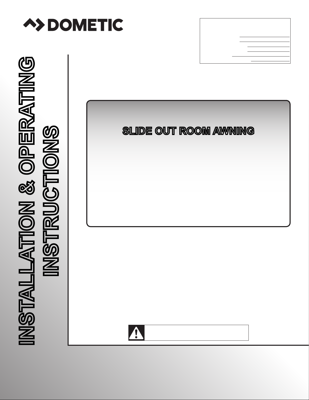
1. Full extension of slide out room MUST NOT exceed 42″. See (FIG. 1).
See “Slide Topper Sizing” in Application Guide to determine appropriate slide topper width for the slide out
room application.
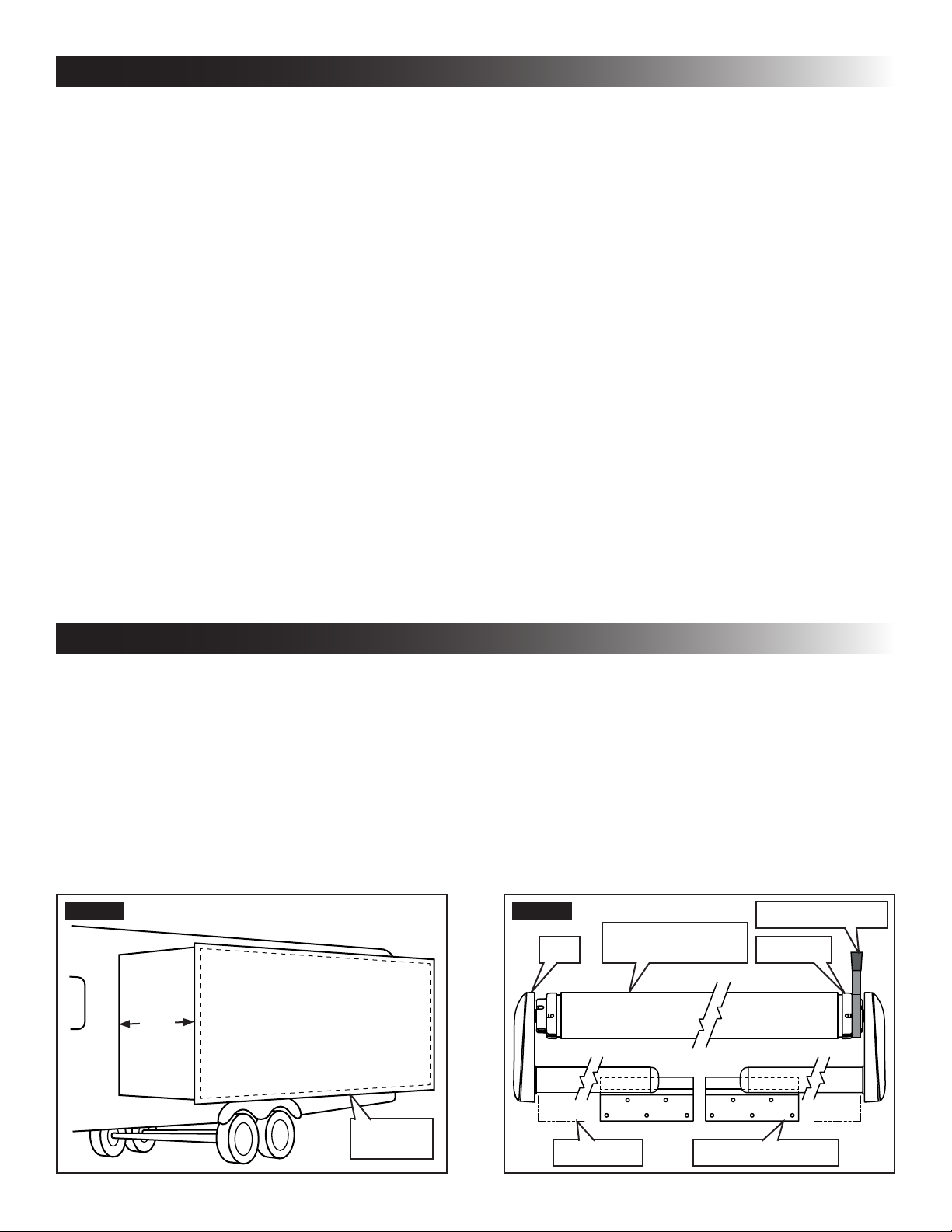
2. Slide Toppers 198″ or wider REQUIRE the following options / kits:
● A second anti-billow stop kit (one at each end cap). See (FIG. 2).
● A second anti-billow bracket kit (one at each end cap).
● A cradle kit for center support (of FRTA).
See “B. Optional Components & Kits” on page (4) to order cradle kit.
Slide Toppers 360″ or wider may use a second (optional) cradle kit.
FIG. 1
FIG. 2
Arm
Slide Toppers 360″ or wider may use a second (optional) cradle kit.
Anti-Billow Stop
Fabric Roller Tube
Assembly (FRTA)
End Cap
42″
Maximum
Extension
Slide Out
Room
4
Extension Mounting Bracket
 Loading...