

Dometic Servel RGE400 Installation And Operating Instructions Manual
sli!id
by
Dometic
INSTALLATION AND
OPERATING INSTRUCTIONS
REFRIGERATOR FOR LP-GAS AND ELECTRIC OPERATION.
Model RGE400
FOR YOUR SAFETY
If you smell gas:
1. Open windows.
2. Don’t touch electrical switches.
3. Extinguish any open flame.
4. Immediately call your gas supplier.
FOR YOUR SAFETY
Do not store or use gasoline or other
flammable vapors and liquids in the
vicinity of this or any other appliance.
WARNING: Improper installation,
adjustment, alteration,service or
maintenance can cause injury or
property damage. Refer to this
manual. For assistance or additional
information consult a qualified
installer, service agency or the gas
supplier.
Contents:
Page
Installation
2
Operating Instructions
3
Maintenance & Service
5
Cet appareil cloit
6tre repare
seulement par un
reparateur
autorise. Modification de
I’appareil pourrait etre
extremement
dangeruse, et
pourrait causer mal ou mort.
AVIS
RECORD THIS INFORMATION FOR FUTURE
REFERENCE BEFORE INSTALLING THE
UNlT:
Model No.
......................... Serial No.
........................
Product No.
.......................
DatePurchased
................
PlaceofPurchase
.......................................................
Corporate Office
2320 Industrial Parkway
Elkhart,
IN 46515
USA
Service Office
The
Dometic
Corporation
509 South Poplar Street
LaGrange, IN 46761
Phone: 219-463-4858
For Service Center Assistance
Call: 800-544-4881
CANADA
Dometic
Distribution Inc.
866 Langs Drive
Cambridge,Ontario
N3H 2N7
Canada
Phone: 519-653-4390
I
822 70 58-00
INSTALLATION
GENERAL INSTRUCTION
This appliance is designed for storage of foods
and storage of frozen foods and making ice.
The refrigerator outlined herein have been design certified by A.G.A. under the ANSI
Z21 .19
Refrigerator Stan-
dard, for a free-standing installation and is also approved
by the Canadian Gas Association.
The certifications are, however contingent on the instal-
lation being made in accordance with the following in-
structions as applicable.
In the U.S.A., the installation must conform with:
1.
National Fuel Gas Code ANSI 2223.1 -(latest edition)
2.
Manufactured Home Construction and Safety Standard, Title 24 CFR, Part 3280.
3.
Any applicable local code.
The unit must be electrically grounded in accordance
with the National Electric Code
ANSI/NFPA
70-(latest
edition) when installed, if an external alternating current
electrical source is utilized.
In CANADA, the installation must conform with:
1.
Current CAN/CGA B149 Gas Installation Codes
2.
Where a flexible metal connector is used, it must
comply with the provisions of the current Standard
CAN1-6.10, METAL CONNECTORS FOR GAS
APPLIANCES.
3.
Any applicable local code
The unit must be electrically grounded in accordance
with the current CANADIAN ELECTRICAL CODE C22
Parts 1 and 2.
FREE-STANDING MODEL FOR
FLOOR INSTALLATION ONLY
The room must be well ventilated and not used as a
bedroom.
Further the room should have a window (which can be
opened) or a door to the outside.
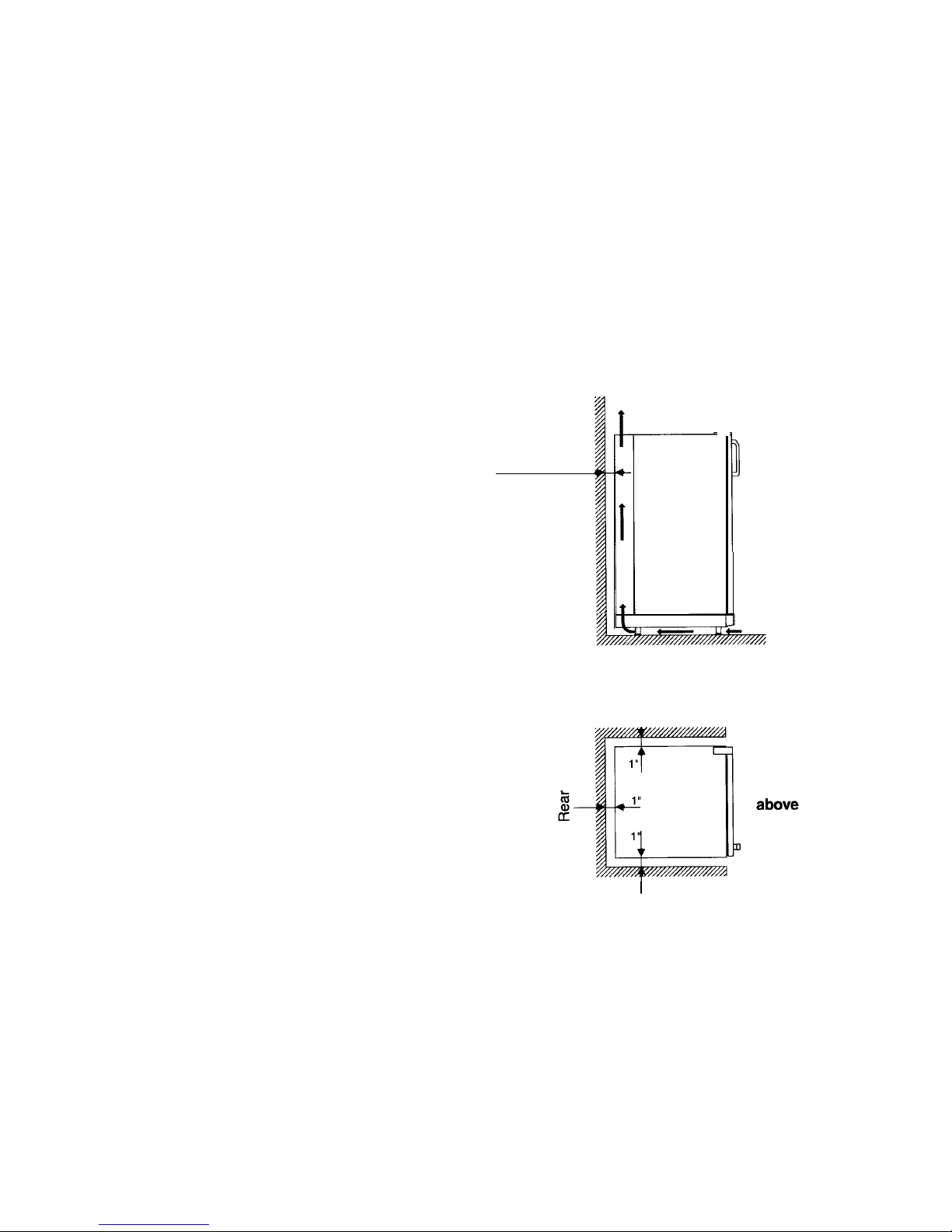
For best performance also at high ambient temperatures
there must be a free air circulation over the cooling unit
at the rear of the refrigerator.
Ensure that there is a free space of at least 4 inches (100
mm) above the refrigerator and that the ventilation ope-
ning on the top of the cabinet is not covered in any way.
Do not place the refrigerator in a space where air circulation is restricted.
A clearance of at least 1 inch (25 mm) should be left
between the rear and sides of the refrigerator and the
surrounding walls.
This free-standing refrigerator requires accessibility to
the back for servicing the gas equipment. If allowed by
the Local Authorities, the accessibility can be obtained
by using a certified Flexible Metal Connector of Gas
Hose Assembly which would allow the refrigerator to be
withdrawn without disrupting the gas supply.
However, if the Local Authorities require a rigid gas
supply connector the refrigerator should be located with
sufficient space at the back for servicing or, if located
against a wall, a removable panel of a minimum size of
16” x 20” should be provided in the wall to allow access
to the rear of the refrigerator.
The refrigerator must be adjusted to a vertical position
in both directions.
Use the feet on the refrigerator to adjust its position.
CLEARANCES
Minimum clearances in inches to combustible materials
are:
Top 4”
Side 1”
Rear 1”
Bottom the feet must be in place to ensure free air
circulation.
See Figs. 1
&
2.
At least
1"
(25 mm)
FIG. 1
, Wall
FIG. 2.
I
From the side
1
Wall
From
NOTE: DO NOT install the appliance directly on carpe-
ting. Carpeting must be removed or protected by a metal
or wood panel beneath the appliance, which extends at
least the full width and depth of the appliance.
GAS CONNECTION
Hook-up to the gas supply line is accomplished at the
manual gas shutoff valve, which is furnished with a
3/8”
SAE (UNF 5/8” -18) male flare connection. A backup
wrench must be used when tightening gas supply
fitting.
All completed connections should be checked for
leaks with a noncorrosive leak detector.
2
OPERATING INSTRUCTIONS
DO NOT use a flame to check for gas leaks.
The gas supply system must incorporate a pressure
regulator to maintain a supply pressure of not more than
11 inches water column.
When testing the gas supply system at test pressures in
excess of 1/2 psig, the refrigerator and its individual
shutoff valve must be disconnected from the gas supply
piping system.
When testing the gas supply system at pressures less
than or equal to
1/2
psig, the appliance must be isolated
from the gas supply piping system by closing its individual manual shutoff valve.
In case detailed instructions on the installation and
connection to the gas supply are required, contact your
dealer or distributor.
TESTING LP GAS SAFETY
SHUTOFF
The gas safety shut-off must be tested after the
refrigerator is connected to the LP gas supply.
To test the gas safety shut-off, proceed as follows:
1.
2.
3.
4.
5.
6.
7.
Start
the refrigerator according to the instructions for
Gas Operation, section “Operation Instructions”.
Check that the gas flame is lit. This can be observed
through the reflector (E).
Close the gas valve by turning the knob (A) back to
“OFF” position.
Wait for one minute.
Remove burner cover plate, one screw at the burner.
Open the gas valve by turning the knob (A) to position
“GAS” without pushing the buttons (C) and
(D).
Apply
a non-corrosive commercial bubble solution to the
burner jet.
No bubbles should appear at the opening of the
burner jet. The presence of bubbles indicates a defective gas safety shutoff, and service is required.
If no bubbles were present at the burner jet, the gas
safety valve is working properly. Rinse jet thoroughly
with fresh water before proceeding. Be careful not to
damage the burner jet. Replace burner cover plate
and turn the knob (A) back to “OFF”. Start the refrigerator by following the instructions for Gas Operation,
section “Operation Instructions”. Normal operation of
the burner should return. Allow the burner to operate
for a minimum of 5 minutes.
ELECTRICAL CONNECTION
120 Volt AC Connection
The refrigerator is equipped with a three-prong (ground-
ing) plug for your protection against shock hazards and
should be plugged directly into a properly grounded
three-prong receptacle. DO NOT cut or remove the
grounding prong from this plug. The cord should be
routed to avoid direct contact with the burner cover, flue
cover or any other components that could damage the
cord insulation.
IMPORTANCE OF LEVELING
A REFRIGERATOR
In an absorption refrigerator system, ammonia is liquefied in the finned condenser coil at the top rear of the
refrigerator. The liquid ammonia then flows into the
evaporator (inside the freezer section) and is exposed
to a circulating flow of hydrogen gas, which causes the
ammonia to evaporate, creating a cold condition in the
freezer.
When starting this refrigerator for the very first time, the
cooling cycle may require up to four hours of running
time before the cooling unit is fully operational.
The tubing in the evaporator section is specifically
sloped-to provide a continuous movement of liquid ammonia, flowing downward by gravity through this section.
If the refrigerator is operated when it is not level, liquid
ammonia will accumulate in sections of the evaporator
tubing. This will slow the circulation of hydrogen and
ammonia gas, or in severe cases, completely block it,
resulting in a loss of cooling.
The refrigerator must be adjusted to a vertical position
in both directions.
Use the feet on the refrigerator to adjust its position.
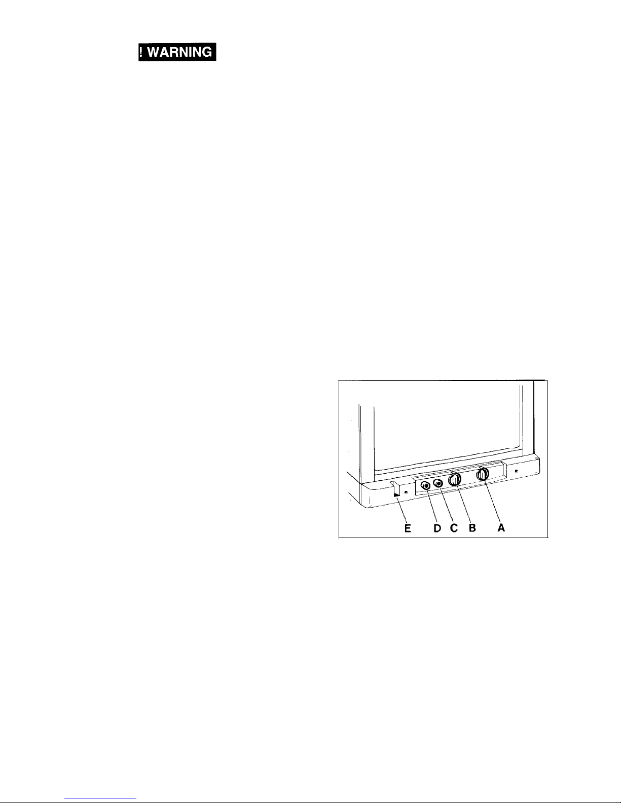
CONTROLS
FIG.3.
The refrigerator can be run on either 120 volt AC or LP
gas. Changing between these modes of operation is
carried out by means of control buttons positioned as
shown in fig. 3.
The energy selector
(A)
can be set at either
“ELEC”
(120
volt AC),
“GAS”
(LP gas) or
“OFF”.
The refrigerator temperature is controlled by a thermostat (B). Please note that the thermostat has no “off”
position.
The refrigerator is fitted with a safety device which
automatically shuts off the supply of gas if the flame goes
out. The safety device can be opened manually by
depressing knob (C).
The piezoelectric igniter discharges sparks over the
burner when the button (D) is pushed.
In the flame viewer
(E) you
can see a blue light when the
flame is alight.
 Loading...